EP1892480B1 - Chauffe eau pour des liquides, utilisation dudit chauffe-eau et méthode de chauffage d'un fluide dans un tel circuit hydraulique - Google Patents
Chauffe eau pour des liquides, utilisation dudit chauffe-eau et méthode de chauffage d'un fluide dans un tel circuit hydraulique Download PDFInfo
- Publication number
- EP1892480B1 EP1892480B1 EP06017454A EP06017454A EP1892480B1 EP 1892480 B1 EP1892480 B1 EP 1892480B1 EP 06017454 A EP06017454 A EP 06017454A EP 06017454 A EP06017454 A EP 06017454A EP 1892480 B1 EP1892480 B1 EP 1892480B1
- Authority
- EP
- European Patent Office
- Prior art keywords
- heat exchanger
- tube
- coaxial
- storage tank
- tube heat
- Prior art date
- Legal status (The legal status is an assumption and is not a legal conclusion. Google has not performed a legal analysis and makes no representation as to the accuracy of the status listed.)
- Not-in-force
Links
Images
Classifications
-
- F—MECHANICAL ENGINEERING; LIGHTING; HEATING; WEAPONS; BLASTING
- F24—HEATING; RANGES; VENTILATING
- F24D—DOMESTIC- OR SPACE-HEATING SYSTEMS, e.g. CENTRAL HEATING SYSTEMS; DOMESTIC HOT-WATER SUPPLY SYSTEMS; ELEMENTS OR COMPONENTS THEREFOR
- F24D3/00—Hot-water central heating systems
- F24D3/08—Hot-water central heating systems in combination with systems for domestic hot-water supply
- F24D3/087—Tap water heat exchangers specially adapted therefore
-
- F—MECHANICAL ENGINEERING; LIGHTING; HEATING; WEAPONS; BLASTING
- F24—HEATING; RANGES; VENTILATING
- F24D—DOMESTIC- OR SPACE-HEATING SYSTEMS, e.g. CENTRAL HEATING SYSTEMS; DOMESTIC HOT-WATER SUPPLY SYSTEMS; ELEMENTS OR COMPONENTS THEREFOR
- F24D11/00—Central heating systems using heat accumulated in storage masses
- F24D11/002—Central heating systems using heat accumulated in storage masses water heating system
-
- F—MECHANICAL ENGINEERING; LIGHTING; HEATING; WEAPONS; BLASTING
- F24—HEATING; RANGES; VENTILATING
- F24D—DOMESTIC- OR SPACE-HEATING SYSTEMS, e.g. CENTRAL HEATING SYSTEMS; DOMESTIC HOT-WATER SUPPLY SYSTEMS; ELEMENTS OR COMPONENTS THEREFOR
- F24D17/00—Domestic hot-water supply systems
- F24D17/0078—Recirculation systems
- F24D17/0084—Coaxial tubings
Definitions
- the invention relates to a continuous heater for a Nutz sometimeskeit with a storage container which receives a heat-emitting liquid.
- Such continuous heaters are known.
- the term means that the use liquid is heated by flowing inside through the tubes of a heat exchanger, which is heated from the outside.
- the useful liquid is therefore not heated by the fact that a larger reservoir of the liquid is constantly heated.
- a practical application for the continuous heater according to the invention is the provision of utility or service water in residential buildings.
- the service water is needed there for the purposes of the household, the kitchen and in the bath for bathing or showering.
- the special feature of domestic water abstraction is that at irregular intervals highly fluctuating amounts of hot water are to be taken.
- the available amount of removable liquid is often insufficient.
- FIG DE 41 42 488 A1 An example of a prior art continuous-flow heater is shown in FIG DE 41 42 488 A1 ,
- the heating of the useful liquid is combined with the heating of the heating water.
- the exhaust gases of a gas burner flow through a coiled tube, which is formed from a coaxial tube.
- a storage container for the useful liquid is connected downstream of the coaxial tube heat exchanger.
- This storage container is a working according to the displacement principle stratified storage; the useful liquid is conveyed by a charge pump in circulation through the coaxial heat exchanger and the stratified storage. The removal of the useful liquid takes place from the stratified storage.
- FIG. 1 Another embodiment shows a continuous-flow heater according to the DE 198 07 657 C1 ,
- a heat exchanger made of coiled tubes is arranged in a storage container.
- the storage container is filled with water, which is heated by various means.
- a built-in or adjacent boiler can serve.
- a solar system or a heat pump can be used to heat the storage water.
- No own storage is provided for the useful liquid.
- the storage tank In order for the heat capacity of the storage water is sufficient to always heat a sufficient amount of liquid, the storage tank must be sufficiently large, and it must be possible to heat it up briefly strong.
- a large-sized storage heater is used to hold the service or use liquid.
- a heat exchanger made of coiled pipes is also installed in the storage container.
- the tubes are arranged in the manner of a cylindrical thread.
- a first section of the heat exchanger is provided with coaxial tubes, wherein an inner tube is arranged in an outer tube.
- an inner tube enters the cold liquid and enters the inside of the storage container at the end of the inner tube.
- a heat-emitting liquid is performed, which initially fills the entire cross-section of the outer tube and is then guided in the annular space between the outer and inner tube.
- the heat-emitting liquid flows in countercurrent to the use liquid.
- the incoming heat-emitting liquid thus first heats the already in the storage container used useful liquid and then in heat exchange with the inner tube of the coaxial also directly the incoming cold liquid.
- the heat-releasing liquid becomes thereby already well utilized; but it is still a very large storage tank for the liquid used required.
- a temperature influencing of the respective other heat-emitting medium is achieved via the fresh water flowing in the annular space of the co-axial heat exchanger. It may happen that an overheated coolant by heat transfer to the fresh water, which further warms the carrier medium in the interior.
- DE 195 35 265 C1 shows a located in a container of a hot water heater two-chamber heat exchanger, which is formed of two co-axial helical coiled tubes.
- a useful liquid is displaced into an inner tube of the two-chamber heat exchanger by supplying fresh water in the container, and flows through an outflow, which is connected to the inner tube, from the hot water heater.
- fresh water flows countercurrently into the container.
- a disadvantage of this device is that the entire water in the container must be kept at a certain temperature level, so that water can be removed from the container a certain temperature.
- the invention has for its object to provide a continuous flow heater for a Nutz gallkeit with a storage container which receives a heat-emitting liquid, which can be dispensed by improving the heat transfer to a storage for the Nutz alloykeit.
- a continuous flow heater for a Nutz specialkeit with a storage container which receives a heat-releasing liquid, and with a Koaxialrohr heat exchanger, which is arranged in the storage container and consists of a coiled outer tube and an inner tube located therein, wherein the inner tube is flowed through by the same heat-emitting liquid contained in the storage container, while the ring cross-section between the inner and outer tube is flowed through by the Nutzenberg deviskeit and the inner and outer tube after liquid management and connections are completely separated.
- the useful liquid flowing through the coaxial-tube heat exchanger is simultaneously heated from the inside and from the outside.
- the heating from inside is done by the heat-emitting liquid flowing through the inner tube of the coaxial tube.
- the heating from the outside is carried out by the heat-releasing liquid in the storage container.
- the heat transfer can make very cheap, and also the storage container for the heat-emitting liquid must not be excessively large.
- the embodiment of the invention also has the advantage that not a storage container for the useful liquid (service water), in which the liquid is more often, must be kept clean and germ-free, but only the annulus of the coaxial heat exchanger, which is easier to accomplish with the usual technical and chemical means.
- Claim 11 is directed to a use of the continuous heater according to the invention for the hygienic heating of domestic water in buildings.
- the claims 12 to 14 relate to a hydraulic circuit of a heater for a Nutz problemkeit, wherein by a prior art according to the DE 38 27 585 C2 is assumed.
- the invention is thus also the method for heating a Nutz classickeit by a heat-emitting liquid in a hydraulic circuit with a storage container in which a Koaxialrohr heat exchanger consisting of a coiled outer tube and an inner tube located therein, is arranged, with separate liquid guide and separate terminals inner and outer tube and with the mouth of one end of the inner tube in the interior of the storage container, wherein the hydraulic circuit is such that the Nutz alloykeit is passed through the annular cross-section between the outer tube and the inner tube, while the heat-emitting liquid through the inner tube flows and is contained in the storage container for charging the Koaxialrohr heat exchanger from the outside.
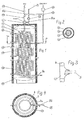
- FIG. 1 shows the continuous heater according to the invention in a longitudinal section. It consists of a storage container 1, which is shown in the embodiment chosen here as a standing container with a vertical longitudinal axis.
- the storage container 1 can be designed as a pressureless or pressure-resistant container and have a divided or closed insulation 17.
- the coaxial tube heat exchanger 2 In the storage container 1, various heat exchangers are housed. In its upper part is the coaxial heat exchanger 2. It extends only over part of the height of the storage container 1 down, in the illustrated embodiment, up to the section line AA.
- the coaxial tube heat exchanger 2 consists of coiled tubes. In the exemplary embodiment, a spiraling in the manner of a cylindrical screw thread, as in a coil spring shown. However, the coaxial tube heat exchanger 2 could also be spiral-shaped or spiral-shaped (as in a conical spring).
- the coiled tubes of the coaxial tube heat exchanger 2 are formed as coaxial tubes, as a cross section through a single tube according to the FIG. 2 shows. There is an inner tube 3 in an outer tube 4, wherein between the inner tube 3 and the outer tube 4, a ring cross-section 6 is formed.
- the solid cross section of the Inner tube 3 is designated by the reference numeral 5.
- Inner and outer tubes 3, 4 may be rigid or flexible.
- the inner tube 3 and the outer tube 4 are guided completely separated after liquid management and connections.
- an upper T-piece 7 and two lower T-pieces 8a and 8b are provided.
- the upper T-piece 7 is provided at the top of the storage container 1 and in FIG. 3 shown enlarged.
- Figures 1 and 2 shows that via the upper T-piece 7, the inner tube 3 is guided to a first switching valve 14a and the outer tube 4 to a second switching valve 14b.
- the lower tees 8a and 8b are located at the lower end of the coaxial tube heat exchanger 2 and are in FIG. 4 shown enlarged. The continuing connections are in FIG. 4 also indicated.
- the inner tube 3 of the coaxial tube heat exchanger 2 is thus sealed out through the first lower T-piece 8 a and the second lower T-piece 8 b. It is brought into contact with the interior of the storage container 1 at a location, not shown. However, it can also be fed directly to the interior of the storage container 1 via the first lower T-piece 8a.
- the outer tube 4 of the coaxial tube heat exchanger 2 communicates via the two tees 8 a and 8 b with a circulation line 15, which is guided to the second switching valve 14 b, but is also in communication with a pump 16.
- FIG. 4 does not immediately indicate that there is also a downwardly opening at the first lower tee 8a;
- the first lower T-piece thus forms a spatial or double tee.
- the outer tube 4 is connected to a normal pipe heat exchanger 9 in connection.
- auxiliary heat exchangers 10, 11, 12 Concentrically surrounding the coaxial tube heat exchanger 2 and the normal tube heat exchanger 9, three additional heat exchangers 10, 11 and 12 with separate own connections are also provided in the storage container 1.
- the auxiliary heat exchangers 10, 11, 12 may for example be connected to solar registers or to a system for heat recovery.
- the heat-emitting liquid is supplied by means of a pump 13 to the hitherto described flow heater via the connecting line 20.
- the heat-releasing liquid passes into the solid cross section 5 of the inner tube 3, which is located in the coaxial tube heat exchanger 2.
- the first switching valve 14a and the lower tees 8a and 8b there is also a connection to the interior of the storage container 1.
- the heat-releasing liquid can pass through the storage container 1 and the solid cross-section 5 the inner tube 3 are promoted. In this case, a cycle through the inner tube 3 is possible without that heat-emitting liquid is supplied from the outside.
- the same heat-emitting liquid acts on the ring cross-section 6 of the coaxial tube heat exchanger 2 both from the inside and from the outside.
- the respectively desired and required flow state of the heat-emitting liquid can be controlled in accordance with a first temperature sensor 18 (measuring point) which monitors the temperature of the useful liquid.
- the useful liquid is fed via the connection 9a to the normal-tube heat exchanger 9 and arrives at the transition point at the first lower T-piece 8a in the annular cross-section 6 of the coaxial heat exchanger 2. It then flows as needed on the upper T-piece 7 and second switching valve 14b to the consumer.
- the Nutzfiüsstechnik but can also be performed in the circulation through the circulation line 15.
- the desired flow guidance can be adjusted automatically or manually in accordance with a second temperature sensor 19.
- the two liquids can basically be conducted in countercurrent or direct current within the coaxial tube heat exchanger.
- the preferred field of application of the described continuous-flow heater is the hygienic heating of domestic water in buildings. Therefore, as the working water is usually supplied cold water. This heats up as it flows through the normal-pipe heat exchanger 9, because it is acted upon from the outside by the heat-emitting liquid, which is located in the storage container 1. When flowing through the coaxial heat exchanger 2 is still the heating from the inside is added, because the located in the inner tube 3 heat-emitting liquid also heats the Nutztlerkeit.
- the additional heat exchangers 10, 11, 12 can additionally heat the heat-releasing liquid present in the storage container 1, which acts on the normal-tube heat exchanger 9 and the coaxial-tube heat exchanger 2 from the outside.
- These additional heat exchangers 10, 11, 12 can be arranged individually or together. They are particularly advantageous when additional heat sources such as solar registers or systems for heat recovery are available, which are independent of the heat source through which the heat-dissipating liquid supplied to the water heater has received its heat at the beginning.
- the purpose of the described arrangement is the heating of industrial water. If there is a cooled liquid in the storage container 1 and the solid cross-section of the inner tube 3, a cooling effect naturally results for the use liquid.
- the useful liquid is withdrawn as needed via the second switching valve 14b.
- the outlet temperature is monitored via the second temperature sensor (measuring point) 19. If the outlet temperature is too high, the Useful liquid also be passed completely or as a partial flow through the circulation line 15 in the circuit through the coaxial heat exchanger.
- the circulation line 15 can also be used to clean by means of the pump 16, the lines of water of the continuous flow heater, for example, also for the control of Legionella.
Landscapes
- Engineering & Computer Science (AREA)
- Physics & Mathematics (AREA)
- Thermal Sciences (AREA)
- Chemical & Material Sciences (AREA)
- Combustion & Propulsion (AREA)
- Mechanical Engineering (AREA)
- General Engineering & Computer Science (AREA)
- Water Supply & Treatment (AREA)
- Instantaneous Water Boilers, Portable Hot-Water Supply Apparatuses, And Control Of Portable Hot-Water Supply Apparatuses (AREA)
- Heat-Exchange Devices With Radiators And Conduit Assemblies (AREA)
Claims (14)
- Chauffe-eau continu pour un liquide utilitaire, avec un réservoir d'accumulation (1), qui contient un liquide cédant de la chaleur, et avec un échangeur de chaleur à tubes coaxiaux (2), qui est disposé dans le réservoir d'accumulation (1) et qui se compose d'un tube extérieur hélicoïdal (4) ainsi que d' un tube intérieur (3) se trouvant dans celui-ci tandis que la section transversale annulaire (6) entre le tube intérieur (3) et le tube extérieur (4) est parcourue par le liquide utilitaire et les tubes intérieur et extérieur (3, 4) sont entièrement séparés au niveau du guidage des liquides et des raccord, caractérisé en ce que dans lequel le tube intérieur (3) est parcouru par le même liquide cédant de la chaleur que celui qui est contenu dans le réservoir d'accumulation (1).
- Chauffe-eau continu selon la revendication 1, dans lequel le réservoir d'accumulation (1) se présente sous la forme d'un réservoir stationnaire avec un axe longitudinal vertical et le tube extérieur hélicoïdal (4) et le tube intérieur de l'échangeur de chaleur à tubes coaxiaux (2) sont enroulés à la manière de filets de vis disposés en spirale ou cylindriques, dont l'axe central correspond sensiblement à celui du réservoir d'accumulation (1) .
- Chauffe-eau continu selon la revendication 1 ou 2, dans lequel le tube intérieur de l'échangeur de chaleur à tubes coaxiaux (2) est conduit à travers le tube extérieur (4) de l'échangeur de chaleur à tubes coaxiaux (2) en étant chaque fois rendu étanche, au point d'entrée et de sortie du liquide cédant de la chaleur, au moyen de pièces de raccordement en forme de T (7, 8).
- Chauffe-eau continu selon la revendication 2 ou 3, dans lequel l'échangeur de chaleur à tubes coaxiaux (2) se trouve en haut dans le réservoir d'accumulation (1), ne s'étend que sur une partie de la hauteur de celui-ci et un échangeur de chaleur à tube normal (9) est disposé dans le réservoir d'accumulation (1) en dessous de l'échangeur de chaleur à tubes coaxiaux (2), dans lequel la disposition est réalisée de telle manière que la section transversale circulaire de l'échangeur de chaleur à tube normal (9) et la section transversale annulaire (6) de l'échangeur de chaleur à tubes coaxiaux (2) soient parcourues l'une après l'autre de bas en haut par le liquide utilitaire, donc que l'échangeur de chaleur à tube normal (9) soit installé avant l'échangeur de chaleur à tubes coaxiaux (2).
- Chauffe-eau continu selon la revendication 4, dans lequel l'échangeur de chaleur à tube normal (9) se compose d'un tube hélicoïdal en acier spécial, qui est enroulé à la manière de filets de vis cylindriques.
- Chauffe-eau continu selon l'une quelconque des revendications 3 à 5, dans lequel le point d'entrée pour le liquide cédant de la chaleur se situe en haut sur l'échangeur de chaleur à tubes coaxiaux (2) et le point de sortie est disposé dans la région de transition entre l'échangeur de chaleur à tubes coaxiaux (2) et l'échangeur de chaleur à tube normal (9).
- Chauffe-eau continu selon la revendication 6, dans lequel le tube intérieur (3) de l'échangeur de chaleur à tubes coaxiaux (2) débouche au point de sortie dans le réservoir d'accumulation (1).
- Chauffe-eau continu selon la revendication 6, dans lequel le tube intérieur (3) de l'échangeur de chaleur à tubes coaxiaux (2) est conduit vers l'extérieur à travers le réservoir d'accumulation (1) en étant rendu étanche au point de sortie.
- Chauffe-eau continu selon l'une quelconque des revendications 4 à 8, avec un ou plusieurs échangeurs de chaleur supplémentaires (10, 11, 12) qui, sous la forme de tubes normaux en forme de filets de vis cylindriques, entourent localement l'échangeur de chaleur à tube normal (9) et qui sont parcourus par un liquide cédant de la chaleur, qui est guidé et chauffé séparément du liquide cédant de la chaleur qui se trouve dans le tube intérieur (3) de l'échangeur de chaleur à tubes coaxiaux (2) et dans le réservoir d'accumulation (1).
- Chauffe-eau continu selon la revendication 9, dans lequel les échangeurs de chaleur supplémentaires (10, 11, 12) sont raccordés à un registre solaire ou à un système de récupération de chaleur.
- Utilisation d'un chauffe-eau continu selon les revendications 1 à 10 pour le chauffage hygiénique d'eau utilitaire dans des bâtiments.
- Procédé pour chauffer un liquide utilitaire au moyen d'un liquide cédant de la chaleur dans un circuit hydraulique avec un réservoir d'accumulation (1), dans lequel un échangeur de chaleur à tubes coaxiaux (2), composé d'un tube extérieur hélicoïdal (4) et d'un tube intérieur (3) se trouvant dans celui-ci, avec un guidage de liquide séparé et des raccords séparés pour les tubes intérieur et extérieur (3, 4), dans lequel le circuit hydraulique est réalisé de telle manière que le liquide utilitaire soit conduit à travers la section transversale annulaire (6) entre le tube extérieur (4) et le tube intérieur (3), tandis que ce même liquide cédant de la chaleur circule à travers le tube intérieur (3) et est contenu dans le réservoir d'accumulation (1) pour alimenter de l'extérieur l'échangeur de chaleur à tubes coaxiaux.
- Procédé selon la revendication 12, dans lequel, selon la position d'une première soupape d'inversion (14a), le liquide cédant de la chaleur présent dans le tube intérieur (3) de l'échangeur de chaleur à tubes coaxiaux (2) est soit envoyé en circulation thermique dans le circuit soit, en cas de descente en dessous d'une température déterminée du liquide utilitaire à la sortie de l'échangeur de chaleur à tubes coaxiaux (2), utilisé comme courant d'appoint chauffé.
- Procédé selon la revendication 12 ou 13, dans lequel le liquide utilitaire est, selon sa température à la sortie de l'échangeur de chaleur à tubes coaxiaux (2), soit fourni directement au point de consommation soit envoyé totalement ou partiellement dans le circuit vers l'échangeur de chaleur à tubes coaxiaux (2), dans lequel la conduite de circulation (15) utilisée à cet effet peut aussi être inversée pour le nettoyage et la décontamination de l'échangeur de chaleur à tubes coaxiaux (2).
Priority Applications (4)
| Application Number | Priority Date | Filing Date | Title |
|---|---|---|---|
| PL06017454T PL1892480T3 (pl) | 2006-08-22 | 2006-08-22 | Grzejnik przepływowy na ciecz użytkową, zastosowanie grzejnika przepływowego i sposób ogrzewania cieczy użytkowej w takim układzie hydraulicznym |
| EP06017454A EP1892480B1 (fr) | 2006-08-22 | 2006-08-22 | Chauffe eau pour des liquides, utilisation dudit chauffe-eau et méthode de chauffage d'un fluide dans un tel circuit hydraulique |
| DE502006008389T DE502006008389D1 (de) | 2006-08-22 | 2006-08-22 | Durchlauf-Erhitzer für eine Nutzflüssigkeit, Verwendung des Durchlauf-Erhitzers und Verfahren zum Erhitzen einer Nutzflüssigkeit in einer solchen hydraulischen Schaltung |
| AT06017454T ATE489587T1 (de) | 2006-08-22 | 2006-08-22 | Durchlauf-erhitzer für eine nutzflüssigkeit, verwendung des durchlauf-erhitzers und verfahren zum erhitzen einer nutzflüssigkeit in einer solchen hydraulischen schaltung |
Applications Claiming Priority (1)
| Application Number | Priority Date | Filing Date | Title |
|---|---|---|---|
| EP06017454A EP1892480B1 (fr) | 2006-08-22 | 2006-08-22 | Chauffe eau pour des liquides, utilisation dudit chauffe-eau et méthode de chauffage d'un fluide dans un tel circuit hydraulique |
Publications (2)
| Publication Number | Publication Date |
|---|---|
| EP1892480A1 EP1892480A1 (fr) | 2008-02-27 |
| EP1892480B1 true EP1892480B1 (fr) | 2010-11-24 |
Family
ID=37314802
Family Applications (1)
| Application Number | Title | Priority Date | Filing Date |
|---|---|---|---|
| EP06017454A Not-in-force EP1892480B1 (fr) | 2006-08-22 | 2006-08-22 | Chauffe eau pour des liquides, utilisation dudit chauffe-eau et méthode de chauffage d'un fluide dans un tel circuit hydraulique |
Country Status (4)
| Country | Link |
|---|---|
| EP (1) | EP1892480B1 (fr) |
| AT (1) | ATE489587T1 (fr) |
| DE (1) | DE502006008389D1 (fr) |
| PL (1) | PL1892480T3 (fr) |
Families Citing this family (3)
| Publication number | Priority date | Publication date | Assignee | Title |
|---|---|---|---|---|
| DE102011014640B4 (de) * | 2010-03-26 | 2015-07-16 | Jürgen Falkenstein | Kühlungs-Vorrichtung für Photovoltaikelemente sowie Verfahren zum Einbinden dieser in ein Gebäude-Heizsystem |
| CN109532406A (zh) * | 2018-12-20 | 2019-03-29 | 杨新明 | 免能耗汽车用暖风系统 |
| WO2025091106A1 (fr) * | 2023-10-30 | 2025-05-08 | Iron Core Welding Ltd. | Chauffe-eau amélioré et procédés d'utilisation |
Citations (1)
| Publication number | Priority date | Publication date | Assignee | Title |
|---|---|---|---|---|
| DE102005019856A1 (de) * | 2005-04-28 | 2006-11-16 | Sun-Systems Gmbh | Durchlauf-Erhitzer für eine Nutzflüssigkeit, Verwendung des Durchlauf-Erhitzers und hydraulische Schaltung |
Family Cites Families (8)
| Publication number | Priority date | Publication date | Assignee | Title |
|---|---|---|---|---|
| BE757922A (fr) * | 1969-10-24 | 1971-04-01 | Ygnis Sa | Echangeur de chaleur et procede pour son exploitation |
| DE8705241U1 (de) * | 1987-04-08 | 1988-08-11 | Robionek, Hans-Joachim, 4650 Gelsenkirchen | Brauchwasserspeichererhitzer |
| DE3827585A1 (de) * | 1988-08-13 | 1990-02-15 | Rehberg Gmbh Fa | Brauchwasserspeichererhitzer |
| DE4142488A1 (de) * | 1991-12-20 | 1993-07-01 | Ruhrgas Ag | Beheizungssystem zur kombinierten waermeerzeugung und eine heizungsanlage und einen speicherbehaelter fuer brauchwasser |
| DE29515195U1 (de) * | 1995-09-22 | 1995-11-30 | Stiebel Eltron GmbH & Co. KG, 37603 Holzminden | Heißwasserbereiter |
| DE19807657C1 (de) * | 1998-02-24 | 1999-07-01 | Ivt Installations Und Verbindu | Wärmespeicher |
| NL1013648C1 (nl) * | 1999-11-23 | 2001-05-28 | Heatex Bv | Anti-Legionella warmtewisselaar en tapwaterverwarmingsinstallatie met een dergelijke warmtewisselaar. |
| DE202004009559U1 (de) * | 2004-06-16 | 2004-09-23 | Dietz, Erwin | Wärmetauscher |
-
2006
- 2006-08-22 AT AT06017454T patent/ATE489587T1/de active
- 2006-08-22 EP EP06017454A patent/EP1892480B1/fr not_active Not-in-force
- 2006-08-22 PL PL06017454T patent/PL1892480T3/pl unknown
- 2006-08-22 DE DE502006008389T patent/DE502006008389D1/de active Active
Patent Citations (1)
| Publication number | Priority date | Publication date | Assignee | Title |
|---|---|---|---|---|
| DE102005019856A1 (de) * | 2005-04-28 | 2006-11-16 | Sun-Systems Gmbh | Durchlauf-Erhitzer für eine Nutzflüssigkeit, Verwendung des Durchlauf-Erhitzers und hydraulische Schaltung |
Also Published As
| Publication number | Publication date |
|---|---|
| ATE489587T1 (de) | 2010-12-15 |
| DE502006008389D1 (de) | 2011-01-05 |
| EP1892480A1 (fr) | 2008-02-27 |
| PL1892480T3 (pl) | 2011-05-31 |
Similar Documents
| Publication | Publication Date | Title |
|---|---|---|
| EP2217875B1 (fr) | Procede de brassage et brasserie | |
| EP0683362A1 (fr) | Accumulateur de chaleur | |
| EP0099875B1 (fr) | Dispositif pour chauffer de l'eau de chauffage et de l'eau de consommation | |
| EP1170554A2 (fr) | Ensemble et procédé pour préparer de l'eau chaude sanitaire | |
| EP3705789B1 (fr) | Système d'alimentation en eau et son procédé de fonctionnement | |
| DE19855390A1 (de) | Solar-Heizungsanlage und passender Wasser-Pufferspeicher | |
| EP1892480B1 (fr) | Chauffe eau pour des liquides, utilisation dudit chauffe-eau et méthode de chauffage d'un fluide dans un tel circuit hydraulique | |
| EP3617601B1 (fr) | Système d'eau chaude, en particulier installation de chauffage d'eau potable et de conduites d'eau potable | |
| DE102005019856B4 (de) | Durchlauf-Erhitzer für eine Nutzflüssigkeit und hydraulische Schaltung | |
| DE4442222C2 (de) | Wärmeübergabestation | |
| DE3727442A1 (de) | Verfahren zur erzeugung von warmwasser und vorrichtung zur durchfuehrung dieses verfahrens | |
| DE19517250A1 (de) | Gasheizgerät | |
| DE2835072C2 (de) | Wassererhitzer | |
| AT505443B1 (de) | Vorrichtung zur entnahme von wärme aus einem wärmeträgerspeicher | |
| EP2339247B1 (fr) | Procédé de chauffage d'eau non potable | |
| EP2469193B1 (fr) | Procédé pour fournir un fluide secondaire | |
| DE3115697C2 (fr) | ||
| DE29816006U1 (de) | Haus- oder Raumheizungssystem mit Wärmespeicherung | |
| EP0454744B1 (fr) | Dispositif pour la preparation d'eau chaude | |
| DE102004038546A1 (de) | Anordnung zur Bereitstellung von warmem Brauchwasser und Wärmetauscher | |
| DE4300292A1 (de) | Warmwasserversorgung | |
| DE2007061A1 (de) | Wärmeaustauscher | |
| DE19919003A1 (de) | Kombispeicher für die Speicherung von Heiz- und Trinkwasser | |
| EP1724415A2 (fr) | Accumulateur controllé avec deux zones pour la préparation d'eau chaude sanitaire fraîche | |
| DE3827585A1 (de) | Brauchwasserspeichererhitzer |
Legal Events
| Date | Code | Title | Description |
|---|---|---|---|
| PUAI | Public reference made under article 153(3) epc to a published international application that has entered the european phase |
Free format text: ORIGINAL CODE: 0009012 |
|
| 17P | Request for examination filed |
Effective date: 20060822 |
|
| AK | Designated contracting states |
Kind code of ref document: A1 Designated state(s): AT BE BG CH CY CZ DE DK EE ES FI FR GB GR HU IE IS IT LI LT LU LV MC NL PL PT RO SE SI SK TR |
|
| AX | Request for extension of the european patent |
Extension state: AL BA HR MK YU |
|
| AKX | Designation fees paid |
Designated state(s): AT BE BG CH CY CZ DE DK EE ES FI FR GB GR HU IE IS IT LI LT LU LV MC NL PL PT RO SE SI SK TR |
|
| TPAC | Observations filed by third parties |
Free format text: ORIGINAL CODE: EPIDOSNTIPA |
|
| RTI1 | Title (correction) |
Free format text: CONTINUOUS FLOW-HEATER FOR FLUID, USE OF SAID CONTINUOS-FLOW HEATER AND METHOD OF HEATING A WORKFLUID IN SUCH A HYDRAULIC CIRCUIT |
|
| GRAP | Despatch of communication of intention to grant a patent |
Free format text: ORIGINAL CODE: EPIDOSNIGR1 |
|
| GRAS | Grant fee paid |
Free format text: ORIGINAL CODE: EPIDOSNIGR3 |
|
| GRAA | (expected) grant |
Free format text: ORIGINAL CODE: 0009210 |
|
| AK | Designated contracting states |
Kind code of ref document: B1 Designated state(s): AT BE BG CH CY CZ DE DK EE ES FI FR GB GR HU IE IS IT LI LT LU LV MC NL PL PT RO SE SI SK TR |
|
| REG | Reference to a national code |
Ref country code: GB Ref legal event code: FG4D Free format text: NOT ENGLISH |
|
| REG | Reference to a national code |
Ref country code: CH Ref legal event code: EP |
|
| REG | Reference to a national code |
Ref country code: IE Ref legal event code: FG4D |
|
| REF | Corresponds to: |
Ref document number: 502006008389 Country of ref document: DE Date of ref document: 20110105 Kind code of ref document: P |
|
| REG | Reference to a national code |
Ref country code: NL Ref legal event code: T3 |
|
| REG | Reference to a national code |
Ref country code: CH Ref legal event code: NV Representative=s name: E. BLUM & CO. AG PATENT- UND MARKENANWAELTE VSP |
|
| LTIE | Lt: invalidation of european patent or patent extension |
Effective date: 20101124 |
|
| PG25 | Lapsed in a contracting state [announced via postgrant information from national office to epo] |
Ref country code: LT Free format text: LAPSE BECAUSE OF FAILURE TO SUBMIT A TRANSLATION OF THE DESCRIPTION OR TO PAY THE FEE WITHIN THE PRESCRIBED TIME-LIMIT Effective date: 20101124 |
|
| PG25 | Lapsed in a contracting state [announced via postgrant information from national office to epo] |
Ref country code: FI Free format text: LAPSE BECAUSE OF FAILURE TO SUBMIT A TRANSLATION OF THE DESCRIPTION OR TO PAY THE FEE WITHIN THE PRESCRIBED TIME-LIMIT Effective date: 20101124 Ref country code: LV Free format text: LAPSE BECAUSE OF FAILURE TO SUBMIT A TRANSLATION OF THE DESCRIPTION OR TO PAY THE FEE WITHIN THE PRESCRIBED TIME-LIMIT Effective date: 20101124 Ref country code: SI Free format text: LAPSE BECAUSE OF FAILURE TO SUBMIT A TRANSLATION OF THE DESCRIPTION OR TO PAY THE FEE WITHIN THE PRESCRIBED TIME-LIMIT Effective date: 20101124 Ref country code: IS Free format text: LAPSE BECAUSE OF FAILURE TO SUBMIT A TRANSLATION OF THE DESCRIPTION OR TO PAY THE FEE WITHIN THE PRESCRIBED TIME-LIMIT Effective date: 20110324 Ref country code: SE Free format text: LAPSE BECAUSE OF FAILURE TO SUBMIT A TRANSLATION OF THE DESCRIPTION OR TO PAY THE FEE WITHIN THE PRESCRIBED TIME-LIMIT Effective date: 20101124 Ref country code: PT Free format text: LAPSE BECAUSE OF FAILURE TO SUBMIT A TRANSLATION OF THE DESCRIPTION OR TO PAY THE FEE WITHIN THE PRESCRIBED TIME-LIMIT Effective date: 20110324 Ref country code: BG Free format text: LAPSE BECAUSE OF FAILURE TO SUBMIT A TRANSLATION OF THE DESCRIPTION OR TO PAY THE FEE WITHIN THE PRESCRIBED TIME-LIMIT Effective date: 20110224 Ref country code: CY Free format text: LAPSE BECAUSE OF FAILURE TO SUBMIT A TRANSLATION OF THE DESCRIPTION OR TO PAY THE FEE WITHIN THE PRESCRIBED TIME-LIMIT Effective date: 20101124 |
|
| REG | Reference to a national code |
Ref country code: PL Ref legal event code: T3 |
|
| REG | Reference to a national code |
Ref country code: IE Ref legal event code: FD4D |
|
| PG25 | Lapsed in a contracting state [announced via postgrant information from national office to epo] |
Ref country code: GR Free format text: LAPSE BECAUSE OF FAILURE TO SUBMIT A TRANSLATION OF THE DESCRIPTION OR TO PAY THE FEE WITHIN THE PRESCRIBED TIME-LIMIT Effective date: 20110225 |
|
| PG25 | Lapsed in a contracting state [announced via postgrant information from national office to epo] |
Ref country code: ES Free format text: LAPSE BECAUSE OF FAILURE TO SUBMIT A TRANSLATION OF THE DESCRIPTION OR TO PAY THE FEE WITHIN THE PRESCRIBED TIME-LIMIT Effective date: 20110307 Ref country code: EE Free format text: LAPSE BECAUSE OF FAILURE TO SUBMIT A TRANSLATION OF THE DESCRIPTION OR TO PAY THE FEE WITHIN THE PRESCRIBED TIME-LIMIT Effective date: 20101124 Ref country code: CZ Free format text: LAPSE BECAUSE OF FAILURE TO SUBMIT A TRANSLATION OF THE DESCRIPTION OR TO PAY THE FEE WITHIN THE PRESCRIBED TIME-LIMIT Effective date: 20101124 Ref country code: IE Free format text: LAPSE BECAUSE OF FAILURE TO SUBMIT A TRANSLATION OF THE DESCRIPTION OR TO PAY THE FEE WITHIN THE PRESCRIBED TIME-LIMIT Effective date: 20101124 |
|
| PG25 | Lapsed in a contracting state [announced via postgrant information from national office to epo] |
Ref country code: RO Free format text: LAPSE BECAUSE OF FAILURE TO SUBMIT A TRANSLATION OF THE DESCRIPTION OR TO PAY THE FEE WITHIN THE PRESCRIBED TIME-LIMIT Effective date: 20101124 Ref country code: DK Free format text: LAPSE BECAUSE OF FAILURE TO SUBMIT A TRANSLATION OF THE DESCRIPTION OR TO PAY THE FEE WITHIN THE PRESCRIBED TIME-LIMIT Effective date: 20101124 Ref country code: SK Free format text: LAPSE BECAUSE OF FAILURE TO SUBMIT A TRANSLATION OF THE DESCRIPTION OR TO PAY THE FEE WITHIN THE PRESCRIBED TIME-LIMIT Effective date: 20101124 |
|
| PLBE | No opposition filed within time limit |
Free format text: ORIGINAL CODE: 0009261 |
|
| STAA | Information on the status of an ep patent application or granted ep patent |
Free format text: STATUS: NO OPPOSITION FILED WITHIN TIME LIMIT |
|
| 26N | No opposition filed |
Effective date: 20110825 |
|
| REG | Reference to a national code |
Ref country code: DE Ref legal event code: R097 Ref document number: 502006008389 Country of ref document: DE Effective date: 20110825 |
|
| PGFP | Annual fee paid to national office [announced via postgrant information from national office to epo] |
Ref country code: IT Payment date: 20110905 Year of fee payment: 6 |
|
| PG25 | Lapsed in a contracting state [announced via postgrant information from national office to epo] |
Ref country code: MC Free format text: LAPSE BECAUSE OF NON-PAYMENT OF DUE FEES Effective date: 20110831 |
|
| REG | Reference to a national code |
Ref country code: DE Ref legal event code: R119 Ref document number: 502006008389 Country of ref document: DE Effective date: 20120301 |
|
| PG25 | Lapsed in a contracting state [announced via postgrant information from national office to epo] |
Ref country code: IT Free format text: LAPSE BECAUSE OF NON-PAYMENT OF DUE FEES Effective date: 20120822 Ref country code: LU Free format text: LAPSE BECAUSE OF NON-PAYMENT OF DUE FEES Effective date: 20110822 |
|
| PG25 | Lapsed in a contracting state [announced via postgrant information from national office to epo] |
Ref country code: DE Free format text: LAPSE BECAUSE OF NON-PAYMENT OF DUE FEES Effective date: 20120301 |
|
| PG25 | Lapsed in a contracting state [announced via postgrant information from national office to epo] |
Ref country code: TR Free format text: LAPSE BECAUSE OF FAILURE TO SUBMIT A TRANSLATION OF THE DESCRIPTION OR TO PAY THE FEE WITHIN THE PRESCRIBED TIME-LIMIT Effective date: 20101124 |
|
| PG25 | Lapsed in a contracting state [announced via postgrant information from national office to epo] |
Ref country code: HU Free format text: LAPSE BECAUSE OF FAILURE TO SUBMIT A TRANSLATION OF THE DESCRIPTION OR TO PAY THE FEE WITHIN THE PRESCRIBED TIME-LIMIT Effective date: 20101124 |
|
| REG | Reference to a national code |
Ref country code: FR Ref legal event code: PLFP Year of fee payment: 11 |
|
| REG | Reference to a national code |
Ref country code: FR Ref legal event code: PLFP Year of fee payment: 12 |
|
| PGFP | Annual fee paid to national office [announced via postgrant information from national office to epo] |
Ref country code: NL Payment date: 20170823 Year of fee payment: 12 |
|
| PGFP | Annual fee paid to national office [announced via postgrant information from national office to epo] |
Ref country code: FR Payment date: 20170823 Year of fee payment: 12 Ref country code: GB Payment date: 20170824 Year of fee payment: 12 Ref country code: CH Payment date: 20170830 Year of fee payment: 12 |
|
| PGFP | Annual fee paid to national office [announced via postgrant information from national office to epo] |
Ref country code: PL Payment date: 20170817 Year of fee payment: 12 Ref country code: BE Payment date: 20170823 Year of fee payment: 12 Ref country code: AT Payment date: 20170821 Year of fee payment: 12 |
|
| REG | Reference to a national code |
Ref country code: CH Ref legal event code: PL |
|
| REG | Reference to a national code |
Ref country code: NL Ref legal event code: MM Effective date: 20180901 |
|
| REG | Reference to a national code |
Ref country code: AT Ref legal event code: MM01 Ref document number: 489587 Country of ref document: AT Kind code of ref document: T Effective date: 20180822 |
|
| GBPC | Gb: european patent ceased through non-payment of renewal fee |
Effective date: 20180822 |
|
| PG25 | Lapsed in a contracting state [announced via postgrant information from national office to epo] |
Ref country code: AT Free format text: LAPSE BECAUSE OF NON-PAYMENT OF DUE FEES Effective date: 20180822 Ref country code: CH Free format text: LAPSE BECAUSE OF NON-PAYMENT OF DUE FEES Effective date: 20180831 Ref country code: LI Free format text: LAPSE BECAUSE OF NON-PAYMENT OF DUE FEES Effective date: 20180831 |
|
| REG | Reference to a national code |
Ref country code: BE Ref legal event code: MM Effective date: 20180831 |
|
| PG25 | Lapsed in a contracting state [announced via postgrant information from national office to epo] |
Ref country code: NL Free format text: LAPSE BECAUSE OF NON-PAYMENT OF DUE FEES Effective date: 20180901 |
|
| PG25 | Lapsed in a contracting state [announced via postgrant information from national office to epo] |
Ref country code: BE Free format text: LAPSE BECAUSE OF NON-PAYMENT OF DUE FEES Effective date: 20180831 Ref country code: FR Free format text: LAPSE BECAUSE OF NON-PAYMENT OF DUE FEES Effective date: 20180831 |
|
| PG25 | Lapsed in a contracting state [announced via postgrant information from national office to epo] |
Ref country code: GB Free format text: LAPSE BECAUSE OF NON-PAYMENT OF DUE FEES Effective date: 20180822 |
|
| PG25 | Lapsed in a contracting state [announced via postgrant information from national office to epo] |
Ref country code: PL Free format text: LAPSE BECAUSE OF NON-PAYMENT OF DUE FEES Effective date: 20180822 |