EP1892480B1 - Continuous flow-heater for fluid, use of said continuos-flow heater and method of heating a workfluid in such a hydraulic circuit - Google Patents
Continuous flow-heater for fluid, use of said continuos-flow heater and method of heating a workfluid in such a hydraulic circuit Download PDFInfo
- Publication number
- EP1892480B1 EP1892480B1 EP06017454A EP06017454A EP1892480B1 EP 1892480 B1 EP1892480 B1 EP 1892480B1 EP 06017454 A EP06017454 A EP 06017454A EP 06017454 A EP06017454 A EP 06017454A EP 1892480 B1 EP1892480 B1 EP 1892480B1
- Authority
- EP
- European Patent Office
- Prior art keywords
- heat exchanger
- tube
- coaxial
- storage tank
- tube heat
- Prior art date
- Legal status (The legal status is an assumption and is not a legal conclusion. Google has not performed a legal analysis and makes no representation as to the accuracy of the status listed.)
- Not-in-force
Links
Images
Classifications
-
- F—MECHANICAL ENGINEERING; LIGHTING; HEATING; WEAPONS; BLASTING
- F24—HEATING; RANGES; VENTILATING
- F24D—DOMESTIC- OR SPACE-HEATING SYSTEMS, e.g. CENTRAL HEATING SYSTEMS; DOMESTIC HOT-WATER SUPPLY SYSTEMS; ELEMENTS OR COMPONENTS THEREFOR
- F24D3/00—Hot-water central heating systems
- F24D3/08—Hot-water central heating systems in combination with systems for domestic hot-water supply
- F24D3/087—Tap water heat exchangers specially adapted therefore
-
- F—MECHANICAL ENGINEERING; LIGHTING; HEATING; WEAPONS; BLASTING
- F24—HEATING; RANGES; VENTILATING
- F24D—DOMESTIC- OR SPACE-HEATING SYSTEMS, e.g. CENTRAL HEATING SYSTEMS; DOMESTIC HOT-WATER SUPPLY SYSTEMS; ELEMENTS OR COMPONENTS THEREFOR
- F24D11/00—Central heating systems using heat accumulated in storage masses
- F24D11/002—Central heating systems using heat accumulated in storage masses water heating system
-
- F—MECHANICAL ENGINEERING; LIGHTING; HEATING; WEAPONS; BLASTING
- F24—HEATING; RANGES; VENTILATING
- F24D—DOMESTIC- OR SPACE-HEATING SYSTEMS, e.g. CENTRAL HEATING SYSTEMS; DOMESTIC HOT-WATER SUPPLY SYSTEMS; ELEMENTS OR COMPONENTS THEREFOR
- F24D17/00—Domestic hot-water supply systems
- F24D17/0078—Recirculation systems
- F24D17/0084—Coaxial tubings
Definitions
- the invention relates to a continuous heater for a Nutz sometimeskeit with a storage container which receives a heat-emitting liquid.
- Such continuous heaters are known.
- the term means that the use liquid is heated by flowing inside through the tubes of a heat exchanger, which is heated from the outside.
- the useful liquid is therefore not heated by the fact that a larger reservoir of the liquid is constantly heated.
- a practical application for the continuous heater according to the invention is the provision of utility or service water in residential buildings.
- the service water is needed there for the purposes of the household, the kitchen and in the bath for bathing or showering.
- the special feature of domestic water abstraction is that at irregular intervals highly fluctuating amounts of hot water are to be taken.
- the available amount of removable liquid is often insufficient.
- FIG DE 41 42 488 A1 An example of a prior art continuous-flow heater is shown in FIG DE 41 42 488 A1 ,
- the heating of the useful liquid is combined with the heating of the heating water.
- the exhaust gases of a gas burner flow through a coiled tube, which is formed from a coaxial tube.
- a storage container for the useful liquid is connected downstream of the coaxial tube heat exchanger.
- This storage container is a working according to the displacement principle stratified storage; the useful liquid is conveyed by a charge pump in circulation through the coaxial heat exchanger and the stratified storage. The removal of the useful liquid takes place from the stratified storage.
- FIG. 1 Another embodiment shows a continuous-flow heater according to the DE 198 07 657 C1 ,
- a heat exchanger made of coiled tubes is arranged in a storage container.
- the storage container is filled with water, which is heated by various means.
- a built-in or adjacent boiler can serve.
- a solar system or a heat pump can be used to heat the storage water.
- No own storage is provided for the useful liquid.
- the storage tank In order for the heat capacity of the storage water is sufficient to always heat a sufficient amount of liquid, the storage tank must be sufficiently large, and it must be possible to heat it up briefly strong.
- a large-sized storage heater is used to hold the service or use liquid.
- a heat exchanger made of coiled pipes is also installed in the storage container.
- the tubes are arranged in the manner of a cylindrical thread.
- a first section of the heat exchanger is provided with coaxial tubes, wherein an inner tube is arranged in an outer tube.
- an inner tube enters the cold liquid and enters the inside of the storage container at the end of the inner tube.
- a heat-emitting liquid is performed, which initially fills the entire cross-section of the outer tube and is then guided in the annular space between the outer and inner tube.
- the heat-emitting liquid flows in countercurrent to the use liquid.
- the incoming heat-emitting liquid thus first heats the already in the storage container used useful liquid and then in heat exchange with the inner tube of the coaxial also directly the incoming cold liquid.
- the heat-releasing liquid becomes thereby already well utilized; but it is still a very large storage tank for the liquid used required.
- a temperature influencing of the respective other heat-emitting medium is achieved via the fresh water flowing in the annular space of the co-axial heat exchanger. It may happen that an overheated coolant by heat transfer to the fresh water, which further warms the carrier medium in the interior.
- DE 195 35 265 C1 shows a located in a container of a hot water heater two-chamber heat exchanger, which is formed of two co-axial helical coiled tubes.
- a useful liquid is displaced into an inner tube of the two-chamber heat exchanger by supplying fresh water in the container, and flows through an outflow, which is connected to the inner tube, from the hot water heater.
- fresh water flows countercurrently into the container.
- a disadvantage of this device is that the entire water in the container must be kept at a certain temperature level, so that water can be removed from the container a certain temperature.
- the invention has for its object to provide a continuous flow heater for a Nutz gallkeit with a storage container which receives a heat-emitting liquid, which can be dispensed by improving the heat transfer to a storage for the Nutz alloykeit.
- a continuous flow heater for a Nutz specialkeit with a storage container which receives a heat-releasing liquid, and with a Koaxialrohr heat exchanger, which is arranged in the storage container and consists of a coiled outer tube and an inner tube located therein, wherein the inner tube is flowed through by the same heat-emitting liquid contained in the storage container, while the ring cross-section between the inner and outer tube is flowed through by the Nutzenberg deviskeit and the inner and outer tube after liquid management and connections are completely separated.
- the useful liquid flowing through the coaxial-tube heat exchanger is simultaneously heated from the inside and from the outside.
- the heating from inside is done by the heat-emitting liquid flowing through the inner tube of the coaxial tube.
- the heating from the outside is carried out by the heat-releasing liquid in the storage container.
- the heat transfer can make very cheap, and also the storage container for the heat-emitting liquid must not be excessively large.
- the embodiment of the invention also has the advantage that not a storage container for the useful liquid (service water), in which the liquid is more often, must be kept clean and germ-free, but only the annulus of the coaxial heat exchanger, which is easier to accomplish with the usual technical and chemical means.
- Claim 11 is directed to a use of the continuous heater according to the invention for the hygienic heating of domestic water in buildings.
- the claims 12 to 14 relate to a hydraulic circuit of a heater for a Nutz problemkeit, wherein by a prior art according to the DE 38 27 585 C2 is assumed.
- the invention is thus also the method for heating a Nutz classickeit by a heat-emitting liquid in a hydraulic circuit with a storage container in which a Koaxialrohr heat exchanger consisting of a coiled outer tube and an inner tube located therein, is arranged, with separate liquid guide and separate terminals inner and outer tube and with the mouth of one end of the inner tube in the interior of the storage container, wherein the hydraulic circuit is such that the Nutz alloykeit is passed through the annular cross-section between the outer tube and the inner tube, while the heat-emitting liquid through the inner tube flows and is contained in the storage container for charging the Koaxialrohr heat exchanger from the outside.
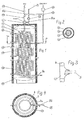
- FIG. 1 shows the continuous heater according to the invention in a longitudinal section. It consists of a storage container 1, which is shown in the embodiment chosen here as a standing container with a vertical longitudinal axis.
- the storage container 1 can be designed as a pressureless or pressure-resistant container and have a divided or closed insulation 17.
- the coaxial tube heat exchanger 2 In the storage container 1, various heat exchangers are housed. In its upper part is the coaxial heat exchanger 2. It extends only over part of the height of the storage container 1 down, in the illustrated embodiment, up to the section line AA.
- the coaxial tube heat exchanger 2 consists of coiled tubes. In the exemplary embodiment, a spiraling in the manner of a cylindrical screw thread, as in a coil spring shown. However, the coaxial tube heat exchanger 2 could also be spiral-shaped or spiral-shaped (as in a conical spring).
- the coiled tubes of the coaxial tube heat exchanger 2 are formed as coaxial tubes, as a cross section through a single tube according to the FIG. 2 shows. There is an inner tube 3 in an outer tube 4, wherein between the inner tube 3 and the outer tube 4, a ring cross-section 6 is formed.
- the solid cross section of the Inner tube 3 is designated by the reference numeral 5.
- Inner and outer tubes 3, 4 may be rigid or flexible.
- the inner tube 3 and the outer tube 4 are guided completely separated after liquid management and connections.
- an upper T-piece 7 and two lower T-pieces 8a and 8b are provided.
- the upper T-piece 7 is provided at the top of the storage container 1 and in FIG. 3 shown enlarged.
- Figures 1 and 2 shows that via the upper T-piece 7, the inner tube 3 is guided to a first switching valve 14a and the outer tube 4 to a second switching valve 14b.
- the lower tees 8a and 8b are located at the lower end of the coaxial tube heat exchanger 2 and are in FIG. 4 shown enlarged. The continuing connections are in FIG. 4 also indicated.
- the inner tube 3 of the coaxial tube heat exchanger 2 is thus sealed out through the first lower T-piece 8 a and the second lower T-piece 8 b. It is brought into contact with the interior of the storage container 1 at a location, not shown. However, it can also be fed directly to the interior of the storage container 1 via the first lower T-piece 8a.
- the outer tube 4 of the coaxial tube heat exchanger 2 communicates via the two tees 8 a and 8 b with a circulation line 15, which is guided to the second switching valve 14 b, but is also in communication with a pump 16.
- FIG. 4 does not immediately indicate that there is also a downwardly opening at the first lower tee 8a;
- the first lower T-piece thus forms a spatial or double tee.
- the outer tube 4 is connected to a normal pipe heat exchanger 9 in connection.
- auxiliary heat exchangers 10, 11, 12 Concentrically surrounding the coaxial tube heat exchanger 2 and the normal tube heat exchanger 9, three additional heat exchangers 10, 11 and 12 with separate own connections are also provided in the storage container 1.
- the auxiliary heat exchangers 10, 11, 12 may for example be connected to solar registers or to a system for heat recovery.
- the heat-emitting liquid is supplied by means of a pump 13 to the hitherto described flow heater via the connecting line 20.
- the heat-releasing liquid passes into the solid cross section 5 of the inner tube 3, which is located in the coaxial tube heat exchanger 2.
- the first switching valve 14a and the lower tees 8a and 8b there is also a connection to the interior of the storage container 1.
- the heat-releasing liquid can pass through the storage container 1 and the solid cross-section 5 the inner tube 3 are promoted. In this case, a cycle through the inner tube 3 is possible without that heat-emitting liquid is supplied from the outside.
- the same heat-emitting liquid acts on the ring cross-section 6 of the coaxial tube heat exchanger 2 both from the inside and from the outside.
- the respectively desired and required flow state of the heat-emitting liquid can be controlled in accordance with a first temperature sensor 18 (measuring point) which monitors the temperature of the useful liquid.
- the useful liquid is fed via the connection 9a to the normal-tube heat exchanger 9 and arrives at the transition point at the first lower T-piece 8a in the annular cross-section 6 of the coaxial heat exchanger 2. It then flows as needed on the upper T-piece 7 and second switching valve 14b to the consumer.
- the Nutzfiüsstechnik but can also be performed in the circulation through the circulation line 15.
- the desired flow guidance can be adjusted automatically or manually in accordance with a second temperature sensor 19.
- the two liquids can basically be conducted in countercurrent or direct current within the coaxial tube heat exchanger.
- the preferred field of application of the described continuous-flow heater is the hygienic heating of domestic water in buildings. Therefore, as the working water is usually supplied cold water. This heats up as it flows through the normal-pipe heat exchanger 9, because it is acted upon from the outside by the heat-emitting liquid, which is located in the storage container 1. When flowing through the coaxial heat exchanger 2 is still the heating from the inside is added, because the located in the inner tube 3 heat-emitting liquid also heats the Nutztlerkeit.
- the additional heat exchangers 10, 11, 12 can additionally heat the heat-releasing liquid present in the storage container 1, which acts on the normal-tube heat exchanger 9 and the coaxial-tube heat exchanger 2 from the outside.
- These additional heat exchangers 10, 11, 12 can be arranged individually or together. They are particularly advantageous when additional heat sources such as solar registers or systems for heat recovery are available, which are independent of the heat source through which the heat-dissipating liquid supplied to the water heater has received its heat at the beginning.
- the purpose of the described arrangement is the heating of industrial water. If there is a cooled liquid in the storage container 1 and the solid cross-section of the inner tube 3, a cooling effect naturally results for the use liquid.
- the useful liquid is withdrawn as needed via the second switching valve 14b.
- the outlet temperature is monitored via the second temperature sensor (measuring point) 19. If the outlet temperature is too high, the Useful liquid also be passed completely or as a partial flow through the circulation line 15 in the circuit through the coaxial heat exchanger.
- the circulation line 15 can also be used to clean by means of the pump 16, the lines of water of the continuous flow heater, for example, also for the control of Legionella.
Landscapes
- Engineering & Computer Science (AREA)
- Physics & Mathematics (AREA)
- Thermal Sciences (AREA)
- Chemical & Material Sciences (AREA)
- Combustion & Propulsion (AREA)
- Mechanical Engineering (AREA)
- General Engineering & Computer Science (AREA)
- Water Supply & Treatment (AREA)
- Instantaneous Water Boilers, Portable Hot-Water Supply Apparatuses, And Control Of Portable Hot-Water Supply Apparatuses (AREA)
- Heat-Exchange Devices With Radiators And Conduit Assemblies (AREA)
Abstract
Description
Die Erfindung betrifft einen Durchlauf-Erhitzer für eine Nutzflüssigkeit mit einem Speicherbehälter, der eine wärme-abgebende Flüssigkeit aufnimmt.The invention relates to a continuous heater for a Nutzflüssigkeit with a storage container which receives a heat-emitting liquid.
Derartige Durchlauf-Erhitzer sind bekannt. Der Ausdruck bedeutet, dass die Nutzflüssigkeit erwärmt wird, indem sie innen durch die Rohre eines Wärmeaustauschers hindurchströmt, der von außen beheizt wird. Die Nutzflüssigkeit wird also nicht etwa dadurch erwärmt, dass ein größerer Vorratsbehälter der Nutzflüssigkeit dauernd beheizt wird. Ein praktisches Anwendungsgebiet für den erfindungsgemäßen Durchlauf-Erhitzer ist die Bereitstellung von Nutz- oder Brauchwasser in Wohngebäuden. Das Brauchwasser wird dort für die Zwecke des Haushalts, der Küche und im Bad zum Baden oder Duschen benötigt. Das Besondere der BrauchwasserEntnahme besteht darin, dass in unregelmäßigen Abständen stark schwankende Mengen von Brauchwasser zu entnehmen sind. Die zur Verfügung stehende Menge an entnehmbarer Nutzflüssigkeit ist oftmals nicht ausreichend.Such continuous heaters are known. The term means that the use liquid is heated by flowing inside through the tubes of a heat exchanger, which is heated from the outside. The useful liquid is therefore not heated by the fact that a larger reservoir of the liquid is constantly heated. A practical application for the continuous heater according to the invention is the provision of utility or service water in residential buildings. The service water is needed there for the purposes of the household, the kitchen and in the bath for bathing or showering. The special feature of domestic water abstraction is that at irregular intervals highly fluctuating amounts of hot water are to be taken. The available amount of removable liquid is often insufficient.
Ein Beispiel für einen Durchlauf-Erhitzer aus dem Stand der Technik zeigt die
Eine andere Ausführung zeigt ein Durchlauf-Erhitzer gemäß der
Wieder eine andere Möglichkeit zeigt die
Durch die getrennte Führung des Kältemittels im Innenrohr und des Trägermediums im Innenraum wird über das im Ringraum des ko-axialen Wärmetauschers strömenden Frischwassers eine Temperaturbeeinflussung des jeweils anderen wärme-abgebenden Mediums erreicht. Dabei kann es vorkommen, dass ein überhitztes Kühlmittel durch Wärmeübertrag auf das Frischwasser, welches weiter das Trägermedium im Innenraum erwärmt.Due to the separate guidance of the refrigerant in the inner tube and the carrier medium in the interior, a temperature influencing of the respective other heat-emitting medium is achieved via the fresh water flowing in the annular space of the co-axial heat exchanger. It may happen that an overheated coolant by heat transfer to the fresh water, which further warms the carrier medium in the interior.
Der Erfindung liegt die Aufgabe zugrunde, einen Durchlauf-Erhitzer für eine Nutzflüssigkeit mit einem Speicherbehälter zu schaffen, der eine wärmeabgebende Flüssigkeit aufnimmt, wobei durch eine Verbesserung des Wärmeüberganges auf einen Vorratsspeicher für die Nutzflüssigkeit verzichtet werden kann.The invention has for its object to provide a continuous flow heater for a Nutzflüssigkeit with a storage container which receives a heat-emitting liquid, which can be dispensed by improving the heat transfer to a storage for the Nutzflüssigkeit.
Die Lösung dieser Aufgabe erfolgt durch die Gesamtheit der Merkmale des Anspruchs 1.The solution of this object is achieved by the entirety of the features of
Sie besteht somit in einem Durchlauf-Erhitzer für eine Nutzflüssigkeit, mit einem Speicherbehälter, der eine wärme-abgebende Flüssigkeit aufnimmt, und mit einem Koaxialrohr-Wärmeaustauscher, der in dem Speicherbehälter angeordnet ist und aus einem gewendelten Außenrohr sowie einem in diesem befindlichen Innenrohr besteht, wobei das Innenrohr von derselben wärme-abgebenden Flüssigkeit durchströmt wird, die in dem Speicherbehälter enthalten ist, während der Ringquerschnitt zwischen dem Innen- und Außenrohr von der Nutzflüssigkeit durchströmt wird und das Innen- und Außenrohr nach Flüssigkeitsführung und Anschlüssen vollständig getrennt sind.It thus consists in a continuous flow heater for a Nutzflüssigkeit, with a storage container which receives a heat-releasing liquid, and with a Koaxialrohr heat exchanger, which is arranged in the storage container and consists of a coiled outer tube and an inner tube located therein, wherein the inner tube is flowed through by the same heat-emitting liquid contained in the storage container, while the ring cross-section between the inner and outer tube is flowed through by the Nutzflüssigkeit and the inner and outer tube after liquid management and connections are completely separated.
Bei dem erfindungsgemäßen Durchlauf-Erhitzer wird die durch den Koaxialrohr-Wärmeaustauscher strömende Nutzflüssigkeit gleichzeitig von innen und von außen aufgeheizt. Das Aufheizen von innen erfolgt durch die wärme-abgebende Flüssigkeit, die durch das Innenrohr des Koaxialrohres strömt. Das Aufheizen von außen erfolgt durch die in dem Speicherbehälter befindliche wärme-abgebende Flüssigkeit. Dadurch lässt sich der Wärmeübergang sehr günstig gestalten, und auch der Speicherbehälter für die wärme-abgebende Flüssigkeit muss nicht übermäßig groß werden. Die erfindungsgemäße Ausgestaltung hat zudem den Vorteil, dass nicht ein Speicherbehälter für die Nutzflüssigkeit (Brauchwasser), in dem die Flüssigkeit öfter steht, sauber und keimfrei gehalten werden muss, sondern nur der Ringraum des Koaxialrohr-Wärmeaustauschers, was mit den üblichen technischen und chemischen Mitteln einfacher zu bewerkstelligen ist.In the continuous-flow heater according to the invention, the useful liquid flowing through the coaxial-tube heat exchanger is simultaneously heated from the inside and from the outside. The heating from inside is done by the heat-emitting liquid flowing through the inner tube of the coaxial tube. The heating from the outside is carried out by the heat-releasing liquid in the storage container. As a result, the heat transfer can make very cheap, and also the storage container for the heat-emitting liquid must not be excessively large. The embodiment of the invention also has the advantage that not a storage container for the useful liquid (service water), in which the liquid is more often, must be kept clean and germ-free, but only the annulus of the coaxial heat exchanger, which is easier to accomplish with the usual technical and chemical means.
Vorteilhafte Ausgestaltungen des erfindungsgemäßen Durchlauf-Erhitzers sind in den Ansprüchen 2 bis 10 angegeben.Advantageous embodiments of the continuous-flow heater according to the invention are specified in
Anspruch 11 ist auf eine Verwendung des erfindungsgemäßen Durchlauf-Erhitzers für die hygienische Erwärmung von Brauchwasser in Gebäuden gerichtet. Die Ansprüche 12 bis 14 betreffen eine hydraulische Schaltung eines Erhitzers für eine Nutzflüssigkeit, wobei von einem Stand der Technik gemäß der
Erfindungsgemäß ist somit auch das Verfahren zum Erhitzen einer Nutzflüssigkeit durch eine wärmeabgebende Flüssigkeit in einer hydraulische Schaltung mit einem Speicherbehälter, in dem ein Koaxialrohr-Wärmeaustauscher, bestehend aus einem gewendelten Außenrohr und einem in diesem befindlichen Innenrohr, angeordnet ist, mit getrennter Flüssigkeitsführung und getrennten Anschlüssen von Innen- und Außenrohr und mit Mündung des einen Endes des Innenrohres in das Innere des Speicherbehälters, wobei die hydraulische Schaltung derart erfolgt, dass die Nutzflüssigkeit durch den Ringquerschnitt zwischen dem Außenrohr und dem Innenrohr geleitet wird, während die wärme-abgebende Flüssigkeit durch das Innenrohr strömt und in dem Speicherbehälter zum Beaufschlagen des Koaxialrohr-Wärmeaustauschers von außen enthalten ist.According to the invention is thus also the method for heating a Nutzflüssigkeit by a heat-emitting liquid in a hydraulic circuit with a storage container in which a Koaxialrohr heat exchanger consisting of a coiled outer tube and an inner tube located therein, is arranged, with separate liquid guide and separate terminals inner and outer tube and with the mouth of one end of the inner tube in the interior of the storage container, wherein the hydraulic circuit is such that the Nutzflüssigkeit is passed through the annular cross-section between the outer tube and the inner tube, while the heat-emitting liquid through the inner tube flows and is contained in the storage container for charging the Koaxialrohr heat exchanger from the outside.
Dank des Verfahrens nach dem Anspruch 12 wird somit aus dem Brauchwasser-Speichererhitzer gemäß der
Vorteilhafte Ausgestaltungen der hydraulischen Schaltung sind in den Ansprüchen 13 und 14 angegeben.Advantageous embodiments of the hydraulic circuit are specified in
Die Erfindung wird anschließend anhand eines in der Zeichnung dargestellten Ausführungsbeispiels noch näher erläutert. In den Figuren ist das Folgende dargestellt:
-
Fig. 1 ist ein Längsschnitt durch einen Durchlauf-Erhitzer gemäß der Erfindung. -
Fig. 2 zeigt in einem Querschnitt das Prinzip des Koaxialrohr-Wärmeaustauschers bei dem erfindungsgemäßen Durchlauf-Erhitzer. -
Fig. 3 verdeutlicht dasDetail 1 derFig. 1 in vergrößerter Darstellung. -
Fig. 4 zeigt den Schnitt gemäß der Linie A-A inFig.1 .
-
Fig. 1 is a longitudinal section through a flow heater according to the invention. -
Fig. 2 shows in a cross section the principle of the coaxial tube heat exchanger in the inventive flow heater. -
Fig. 3 clarifies thedetail 1 of theFig. 1 in an enlarged view. -
Fig. 4 shows the section along the line AA inFig.1 ,
In dem Speicherbehälter 1 sind verschiedene Wärmeaustauscher untergebracht. In seinem oberen Bereich befindet sich der Koaxialrohr-Wärmeaustauscher 2. Er erstreckt sich nur über einen Teil der Höhe des Speicherbehälters 1 nach unten, im dargestellten Ausführungsbeispiel bis zu der Schnittlinie A-A . Der Koaxialrohr-Wärmeaustauscher 2 besteht aus gewendelten Rohren. Im Ausführungsbeispiel ist eine Wendelung nach Art eines zylindrischen Schraubenganges, wie bei einer Schraubenfeder, dargestellt. Der Koaxialrohr-Wärmeaustauscher 2 könnte jedoch auch spiralförmig oder spiralförmig-kegelförmig (wie bei einer Kegelfeder) ausgebildet sein. Die gewendelten Rohre des Koaxialrohr-Wärmeaustauschers 2 sind als Koaxialrohre ausgebildet, wie ein Querschnitt durch ein einzelnes Rohr gemäß der
Das Innenrohr 3 und das Außenrohr 4 sind nach Flüssigkeitsführung und Anschlüssen vollständig getrennt geführt. Zum Anschluss sind ein oberes T-Stück 7 und zwei untere T-Stücke 8a und 8b vorgesehen. Das obere T-Stück 7 ist oben an dem Speicherbehälter 1 vorgesehen und in
Die unteren T-Stücke 8a und 8b befinden sich an dem unteren Ende des Koaxialrohr-Wärmeaustauschers 2 und sind in
Das Außenrohr 4 des Koaxialrohr-Wärmeaustauschers 2 steht über die beiden T-Stücke 8a und 8b mit einer Zirkulationsleitung 15 in Verbindung, die zu dem zweiten Umschaltventil 14b geführt ist, aber auch mit einer Pumpe 16 in Verbindung steht. Aus
Der Normalrohr-Wärmeaustauscher 9 ist als zylindrische Rohrschlange nach Art einer Schraubenfeder ausgebildet Er besteht aus normalen Rohren, beispielsweise aus Edelstahl, mit einem Vollquerschnitt und ist über das erste untere T-Stück 8a mit dem Ringquerschnitt des Koaxialrohr-Wärmeaustauschers 2 in Reihe geschaltet. In dem dargestellten Ausführungsbeispiel reicht er bis in den Bodenbereich des Speicherbehälters 1. Sein Anschluss 9a ist dort nach außen geführt.It consists of normal tubes, for example made of stainless steel, with a solid cross-section and is connected in series via the first lower T-
Den Koaxialrohr-Wärmeaustauscher 2 und den Normalrohr-Wärmeaustauscher 9 konzentrisch umgebend sind in dem Speicherbehälter 1 ferner drei Zusatz-Wärmeaustauscher 10, 11 und 12 mit getrennten eigenen Anschlüssen vorgesehen. Die Zusatz-Wärmeaustauscher 10, 11, 12 können zum Beispiel an Solarregister oder an ein System zur Wärmerückgewinnung angeschlossen sein.Concentrically surrounding the coaxial
Bei seinem bestimmungsgemäßen Gebrauch wird dem bisher beschriebenen Durchlauf-Erhitzer über die Anschlussleitung 20 die wärme-abgebende Flüssigkeit mittels einer Pumpe 13 zugeführt. Über das erste Umschaltventil 14a und das obere T-Stück 7 gelangt die wärme-abgebende Flüssigkeit in den Vollquerschnitt 5 des Innenrohres 3, das sich in dem Koaxialrohr-Wärmeaustauscher 2 befindet. Über das erste Umschaltventil 14a und die unteren T-Stücke 8a und 8b besteht aber auch eine Verbindung zu dem Inneren des Speicherbehälters 1. Mittels thermischer Zirkulation oder durch Zwangsförderung mittels der Pumpe 13 kann die wärme-abgebende Flüssigkeit durch den Speicherbehälter 1 und den Vollquerschnitt 5 des Innenrohres 3 gefördert werden. Dabei ist auch ein Kreislauf durch das Innenrohr 3 möglich, ohne dass wärme-abgebende Flüssigkeit von außen zugeführt wird. Wesentlich ist vor allem, dass dieselbe wärme-abgebende Flüssigkeit den Ringquerschnitt 6 des Koaxialrohr-Wärmeaustauschers 2 sowohl von innen als auch von außen beaufschlagt. Der jeweils gewünschte und erforderliche Strömungszustand der wärme-abgebende Flüssigkeit kann nach Maßgabe eines ersten Temperaturfühlers 18 (Messstelle) gesteuert werden, der die Temperatur der Nutzflüssigkeit überwacht.In its intended use, the heat-emitting liquid is supplied by means of a
Die Nutzflüssigkeit wird über den Anschluss 9a dem Normalrohr-Wärmeaustauscher 9 zugeführt und gelangt an der Übergangsstelle bei dem ersten unteren T-Stück 8a in den Ringquerschnitt 6 des Koaxialrohr-Wärmeaustauschers 2. Sie strömt dann bei Bedarf über das obere T-Stück 7 und das zweite Umschaltventil 14b zum Verbraucher ab. Die Nutzfiüssigkeit kann aber auch im Kreislauf durch die Zirkulationsleitung 15 geführt werden.The useful liquid is fed via the connection 9a to the normal-tube heat exchanger 9 and arrives at the transition point at the first lower T-
Die gewünschte Strömungsführung kann nach Maßgabe eines zweiten Temperaturfühlers 19 automatisch oder von Hand eingestellt werden. Die beiden Flüssigkeiten können innerhalb des Koaxialrohr-Wärmeaustauschers grundsätzlich im Gegenstrom oder Gleichstrom geführt werden.The desired flow guidance can be adjusted automatically or manually in accordance with a
Das bevorzugte Anwendungsgebiet des beschriebenen Durchlauf-Erhitzers ist die hygienische Erwärmung von Brauchwasser in Gebäuden. Daher wird als Nutzwasser in der Regel Kaltwasser zugeführt. Dieses erwärmt sich schon beim Durchströmen des Normalrohr-Wärmeaustauschers 9, weil dieser von außen durch die wärme-abgebende Flüssigkeit beaufschlagt ist, die sich in dem Speicherbehälter 1 befindet. Beim Durchströmen des Koaxialrohr-Wärmeaustauschers 2 kommt noch das Aufheizen von innen hinzu, weil die in dem Innenrohr 3 befindliche wärme-abgebende Flüssigkeit die Nutzflüssigkeit ebenfalls aufheizt.The preferred field of application of the described continuous-flow heater is the hygienic heating of domestic water in buildings. Therefore, as the working water is usually supplied cold water. This heats up as it flows through the normal-pipe heat exchanger 9, because it is acted upon from the outside by the heat-emitting liquid, which is located in the
Die Zusatz-Wärme-Austauscher 10, 11, 12 können die in dem Speicherbehälter 1 befindliche wärme-abgebende Flüssigkeit, welche den Normalrohr-Wärmeaustauscher 9 und den Koaxialrohr-Wärmeaustauscher 2 von außen beaufschlagt, zusätzlich aufheizen. Diese Zusatz-Wärmeaustauscher 10, 11, 12 können einzeln oder gemeinsam angeordnet werden. Sie sind besonders dann vorteilhaft, wenn zusätzliche Wärmequellen wie Solarregister oder Systeme zur Wärmerückgewinnung zur Verfügung stehen, die von derjenigen Wärmequelle unabhängig sind, durch die die dem Durchlauferhitzer zugeführte wärme-abgebende Flüssigkeit ihre Wärme zu Anfang erhalten hat.The
Die Zweckbestimmung der beschriebenen Anordnung ist die Erwärmung von Nutzwasser. Wenn sich in dem Speicherbehälter 1 und dem Vollquerschnitt des Innenrohres 3 eine gekühlte Flüssigkeit befindet, kommt naturgemäß für die Nutzflüssigkeit eine Kühlwirkung zustande.The purpose of the described arrangement is the heating of industrial water. If there is a cooled liquid in the
Die Nutzflüssigkeit wird bei Bedarf über das zweite Umschaltventil 14b abgezogen. Die Austrittstemperatur wird über den zweiten Temperaturfühler (Messstelle) 19 überwacht. Ist die Austrittstemperatur zu hoch, kann die Nutzflüssigkeit auch vollständig oder als Teilstrom über die Zirkulationsleitung 15 im Kreislauf durch den Koaxialrohr-Wärmeaustauscher geleitet werden.The useful liquid is withdrawn as needed via the second switching valve 14b. The outlet temperature is monitored via the second temperature sensor (measuring point) 19. If the outlet temperature is too high, the Useful liquid also be passed completely or as a partial flow through the
Die Zirkulationsleitung 15 kann auch dazu benutzt werden, mittels der Pumpe 16 die das Nutzwasser führenden Leitungen des Durchlauf-Erhitzers zu reinigen, beispielsweise auch zur Bekämpfung von Legionellen.The
- 11
- Speicherbehälterstorage container
- 22
- Koaxialrohr-WärmeaustauscherCoaxial tube heat exchanger
- 33
- Innenrohrinner tube
- 44
- Außenrohrouter tube
- 55
- VollquerschnittFull cross section
- 66
- RingquerschnittRing cross section
- 77
- oberes T-Stückupper tee
- 8a8a
- erstes unteres T-Stückfirst lower tee
- 8b8b
- zweites unteres T-Stücksecond lower tee
- 99
- Normalrohr-WärmeaustauscherNormal tube heat exchanger
- 9a9a
- Anschluss des Normalrohr-WärmeaustauschersConnection of the standard pipe heat exchanger
- 1010
- erster Zusatz-Wärmeaustauscher (oben)first additional heat exchanger (top)
- 1111
- zweiter Zusatz-Wärmeaustauscher (Mitte)second additional heat exchanger (middle)
- 1212
- dritter Zusatz-Wärmeaustauscher (unten)third auxiliary heat exchanger (below)
- 1313
- Pumpepump
- 14a14a
- erstes Umschaltventilfirst changeover valve
- 14b14b
- zweites Umschaltventilsecond changeover valve
- 1515
- Zirkulationsleitungcirculation line
- 1616
- Pumpepump
- 1717
- Isolierunginsulation
- 1818
- erster Temperaturfühler (Messstelle)first temperature sensor (measuring point)
- 1919
- zweiter Temperaturfühler (Messstelle)second temperature sensor (measuring point)
- 2020
- Anschlussleitungconnecting cable
Claims (14)
- Continuous flow heater for a work fluid,
with a storage tank (1) which receives a heat-dispensing liquid,
and with a coaxial tube heat exchanger (2) which is arranged in the storage tank (1) and consists of a coiled outer tube (4) and an inner tube (3) located in the latter, while the work fluid flows through the annular cross section (6) between the inner and outer tube (3, 4), and the inner and outer tube (3, 4) are completely separated in terms of guiding of liquid and connections, characterized in that the same heat-dispensing liquid which is contained in the storage tank (1) flows through the inner tube (3), - Continuous flow heater according to Claim 1, in which the storage tank (1) is designed as an upright-type tank with a vertical longitudinal axis, and the coiled outer tube (4) and inner tube of the coaxial tube heat exchanger (2) are coiled in the manner of spirally arranged or cylindrical screw threads, the central line of which approximately corresponds to that of the storage tank (1).
- Continuous flow heater according to Claim 1 or 2, in which the inner tube of the coaxial tube heat exchanger (2) is in each case guided through the outer tube (4) of the coaxial tube heat exchanger (2) in a manner sealed at the entry and exit point of the heat-dispensing liquid by means of T-shaped connecting pieces (7, 8).
- Continuous flow heater according to Claim 2 or 3, in which the coaxial tube heat exchanger (2) is located at the top of the storage tank (1) and extends only over part of the height of said storage tank, and a standard tube heat exchanger (9) is arranged in the storage tank (1) below the coaxial tube heat exchanger (2), wherein the arrangement is provided in such a manner that the work fluid passes successively from the bottom to the top through the circular cross section of the standard tube heat exchanger (9) and the annular cross section (6) of the coaxial heat exchanger (2), i.e. the standard tube heat exchanger (9) is connected upstream of the coaxial tube heat exchanger (2).
- Continuous flow heater according to Claim 4, in which the standard tube heat exchanger (9) consists of a coiled stainless steel tube which is wound in the manner of cylindrical screw threads.
- Continuous flow heater according to one of Claims 3 to 5, in which the entry point for the heat-dispensing liquid is located at the top of the coaxial tube heat exchanger (2) and the exit point is arranged in the transition region between the coaxial tube heat exchanger (2) and the standard tube heat exchanger (9).
- Continuous flow heater according to Claim 6, in which the inner tube (3) of the coaxial tube heat exchanger (2) leads at the exit point into the storage tank (1).
- Continuous flow heater according to Claim 6, in which the inner tube (3) of the coaxial tube heat exchanger (2) is guided through the storage tank (1) to the outside in a manner sealed at the exit point.
- Continuous flow heater according to one of Claims 4 to 8, with one or more additional heat exchangers (10, 11, 12) which, as standard tubes in the form of cylindrical screw threads, surround sections of the standard tube heat exchanger (9) and through which a heat-dispensing liquid flows, said liquid being guided and heated separately from that heat-dispensing liquid which is located in the inner tube (3) of the coaxial tube heat exchanger (2) and the storage tank (1).
- Continuous flow heater according to Claim 9, in which the additional heat exchangers (10, 11, 12) are connected to a solar register or to a system for recovering heat.
- Use of a continuous flow heater according to Claims 1 to 10 for the hygienic heating of service water in buildings.
- Method of heating a work fluid by means of a heat-dispensing liquid in a hydraulic circuit with a storage tank (1) in which a coaxial tube heat exchanger (2), consisting of a coiled outer tube (4) and an inner tube (3) located in the latter, is arranged, with separate guiding of liquid and separate connections of inner and outer tubes (3, 4), wherein the hydraulic circuit is effected in such a manner that the work fluid is conducted through the annular cross section (6) between the outer tube (4) and the inner tube (3) while said heat-dispensing liquid flows through the inner tube (3) and is contained in the storage tank (1) so as to act upon the coaxial tube heat exchanger from the outside.
- Method according to Claim 12, in which, according to the position of a first switchover valve (14a), the heat-dispensing liquid in the inner tube (3) of the coaxial tube heat exchanger (2) is either circulated thermally in the circuit or, if the work fluid drops below a certain temperature, is operated at the output of the coaxial tube heat exchanger (2) as a heated feed stream.
- Method according to Claim 12 or 13, in which the work fluid, according to the temperature thereof at the exit from the coaxial tube heat exchanger (2), is either supplied directly to the consumption point or is entirely or partially conveyed in the circuit to the coaxial tube heat exchanger (2), wherein the circulation line (15) serving for this purpose can also be switched over for cleaning and disinfecting the coaxial tube heat exchanger (2).
Priority Applications (4)
| Application Number | Priority Date | Filing Date | Title |
|---|---|---|---|
| PL06017454T PL1892480T3 (en) | 2006-08-22 | 2006-08-22 | Continuous flow-heater for fluid, use of said continuos-flow heater and method of heating a workfluid in such a hydraulic circuit |
| AT06017454T ATE489587T1 (en) | 2006-08-22 | 2006-08-22 | CONTINUOUS HEATER FOR A USEFUL FLUID, USE OF THE CONTINUOUS HEATER AND METHOD FOR HEATING A USEFUL FLUID IN SUCH A HYDRAULIC CIRCUIT |
| EP06017454A EP1892480B1 (en) | 2006-08-22 | 2006-08-22 | Continuous flow-heater for fluid, use of said continuos-flow heater and method of heating a workfluid in such a hydraulic circuit |
| DE502006008389T DE502006008389D1 (en) | 2006-08-22 | 2006-08-22 | Continuous flow heater for a utility fluid, use of the continuous flow heater and method for heating a useful fluid in such a hydraulic circuit |
Applications Claiming Priority (1)
| Application Number | Priority Date | Filing Date | Title |
|---|---|---|---|
| EP06017454A EP1892480B1 (en) | 2006-08-22 | 2006-08-22 | Continuous flow-heater for fluid, use of said continuos-flow heater and method of heating a workfluid in such a hydraulic circuit |
Publications (2)
| Publication Number | Publication Date |
|---|---|
| EP1892480A1 EP1892480A1 (en) | 2008-02-27 |
| EP1892480B1 true EP1892480B1 (en) | 2010-11-24 |
Family
ID=37314802
Family Applications (1)
| Application Number | Title | Priority Date | Filing Date |
|---|---|---|---|
| EP06017454A Not-in-force EP1892480B1 (en) | 2006-08-22 | 2006-08-22 | Continuous flow-heater for fluid, use of said continuos-flow heater and method of heating a workfluid in such a hydraulic circuit |
Country Status (4)
| Country | Link |
|---|---|
| EP (1) | EP1892480B1 (en) |
| AT (1) | ATE489587T1 (en) |
| DE (1) | DE502006008389D1 (en) |
| PL (1) | PL1892480T3 (en) |
Families Citing this family (3)
| Publication number | Priority date | Publication date | Assignee | Title |
|---|---|---|---|---|
| DE102011014640B4 (en) * | 2010-03-26 | 2015-07-16 | Jürgen Falkenstein | Cooling device for photovoltaic elements and method for incorporating this in a building heating system |
| CN109532406A (en) * | 2018-12-20 | 2019-03-29 | 杨新明 | Exempt from energy consumption warm-air system for cars |
| WO2025091106A1 (en) * | 2023-10-30 | 2025-05-08 | Iron Core Welding Ltd. | Improved water heater and methods of use |
Citations (1)
| Publication number | Priority date | Publication date | Assignee | Title |
|---|---|---|---|---|
| DE102005019856A1 (en) * | 2005-04-28 | 2006-11-16 | Sun-Systems Gmbh | Flow heater for water heating has inner tube of coaxial tube heat exchanger flow-washed by same heat-yielding fluid which is contained in storage tank, while annular passage between inner and outer tube is flow-washed by usable fluid |
Family Cites Families (8)
| Publication number | Priority date | Publication date | Assignee | Title |
|---|---|---|---|---|
| BE757922A (en) * | 1969-10-24 | 1971-04-01 | Ygnis Sa | HEAT EXCHANGER AND PROCEDURE FOR ITS OPERATION |
| DE8705241U1 (en) * | 1987-04-08 | 1988-08-11 | Robionek, Hans-Joachim, 4650 Gelsenkirchen | Domestic hot water storage heater |
| DE3827585A1 (en) * | 1988-08-13 | 1990-02-15 | Rehberg Gmbh Fa | Storage water heater |
| DE4142488A1 (en) * | 1991-12-20 | 1993-07-01 | Ruhrgas Ag | HEATING SYSTEM FOR COMBINED HEAT GENERATION AND A HEATING SYSTEM AND A STORAGE TANK FOR DOMESTIC WATER |
| DE29515195U1 (en) * | 1995-09-22 | 1995-11-30 | Stiebel Eltron GmbH & Co. KG, 37603 Holzminden | Water heater |
| DE19807657C1 (en) * | 1998-02-24 | 1999-07-01 | Ivt Installations Und Verbindu | Heat store for solar collector |
| NL1013648C1 (en) * | 1999-11-23 | 2001-05-28 | Heatex Bv | Anti-Legionella heat exchanger and tap water heating installation with such a heat exchanger. |
| DE202004009559U1 (en) * | 2004-06-16 | 2004-09-23 | Dietz, Erwin | Heat exchanger for a low-energy house comprises an unpressurized container with an inner chamber having an upper part for direct heat-transfer of condensed refrigerant vapor to fresh water and a lower part for indirect heat transfer |
-
2006
- 2006-08-22 AT AT06017454T patent/ATE489587T1/en active
- 2006-08-22 EP EP06017454A patent/EP1892480B1/en not_active Not-in-force
- 2006-08-22 DE DE502006008389T patent/DE502006008389D1/en active Active
- 2006-08-22 PL PL06017454T patent/PL1892480T3/en unknown
Patent Citations (1)
| Publication number | Priority date | Publication date | Assignee | Title |
|---|---|---|---|---|
| DE102005019856A1 (en) * | 2005-04-28 | 2006-11-16 | Sun-Systems Gmbh | Flow heater for water heating has inner tube of coaxial tube heat exchanger flow-washed by same heat-yielding fluid which is contained in storage tank, while annular passage between inner and outer tube is flow-washed by usable fluid |
Also Published As
| Publication number | Publication date |
|---|---|
| DE502006008389D1 (en) | 2011-01-05 |
| PL1892480T3 (en) | 2011-05-31 |
| EP1892480A1 (en) | 2008-02-27 |
| ATE489587T1 (en) | 2010-12-15 |
Similar Documents
| Publication | Publication Date | Title |
|---|---|---|
| EP2217875B1 (en) | Brewing process and brewery appliance | |
| EP0683362A1 (en) | Heat accumulator | |
| EP0099875B1 (en) | Arrangement for heating central heating water and consumption water | |
| DE19855390C2 (en) | Solar heating system and suitable water buffer storage | |
| EP1170554A2 (en) | System and method for preparing hot sanitary water | |
| EP3705789B1 (en) | Water supply system and method for operating same | |
| EP1892480B1 (en) | Continuous flow-heater for fluid, use of said continuos-flow heater and method of heating a workfluid in such a hydraulic circuit | |
| EP3617601B1 (en) | Hot water system, especially drinking water heating and drinking water line installations | |
| DE102005019856B4 (en) | Continuous heater for a useful fluid and hydraulic circuit | |
| DE4442222C2 (en) | Heat transfer station | |
| DE3727442A1 (en) | METHOD FOR PRODUCING HOT WATER AND DEVICE FOR CARRYING OUT THIS METHOD | |
| DE19517250A1 (en) | Gas-fired water heater with electronically controlled circulation pump | |
| DE2835072C2 (en) | Water heater | |
| AT505443B1 (en) | DEVICE FOR REMOVING HEAT FROM A HEAT CARRIER STORAGE | |
| EP2339247B1 (en) | Method for heating service water | |
| EP2469193B1 (en) | Method for providing a secondary medium | |
| DE3115697C2 (en) | ||
| DE29816006U1 (en) | Home or space heating system with heat storage | |
| EP0454744B1 (en) | Device for supplying hot water | |
| DE102004038546A1 (en) | Arrangement for preparing hot service water comprises a temperature sensor arranged in a secondary circulation system of a heat exchanger | |
| DE4300292A1 (en) | Hot water supply system with at least one container for storing pasteurised water | |
| DE2007061A1 (en) | Heat exchanger | |
| DE19919003A1 (en) | Combination tank for hot and drinking water; has drinking water container with additional water heater above covered part of tank container with coiled flow heater in upper part of container sleeve | |
| EP1724415A2 (en) | Controlled two zone accumulator for fresh sanitary water heating | |
| DE3827585A1 (en) | Storage water heater |
Legal Events
| Date | Code | Title | Description |
|---|---|---|---|
| PUAI | Public reference made under article 153(3) epc to a published international application that has entered the european phase |
Free format text: ORIGINAL CODE: 0009012 |
|
| 17P | Request for examination filed |
Effective date: 20060822 |
|
| AK | Designated contracting states |
Kind code of ref document: A1 Designated state(s): AT BE BG CH CY CZ DE DK EE ES FI FR GB GR HU IE IS IT LI LT LU LV MC NL PL PT RO SE SI SK TR |
|
| AX | Request for extension of the european patent |
Extension state: AL BA HR MK YU |
|
| AKX | Designation fees paid |
Designated state(s): AT BE BG CH CY CZ DE DK EE ES FI FR GB GR HU IE IS IT LI LT LU LV MC NL PL PT RO SE SI SK TR |
|
| TPAC | Observations filed by third parties |
Free format text: ORIGINAL CODE: EPIDOSNTIPA |
|
| RTI1 | Title (correction) |
Free format text: CONTINUOUS FLOW-HEATER FOR FLUID, USE OF SAID CONTINUOS-FLOW HEATER AND METHOD OF HEATING A WORKFLUID IN SUCH A HYDRAULIC CIRCUIT |
|
| GRAP | Despatch of communication of intention to grant a patent |
Free format text: ORIGINAL CODE: EPIDOSNIGR1 |
|
| GRAS | Grant fee paid |
Free format text: ORIGINAL CODE: EPIDOSNIGR3 |
|
| GRAA | (expected) grant |
Free format text: ORIGINAL CODE: 0009210 |
|
| AK | Designated contracting states |
Kind code of ref document: B1 Designated state(s): AT BE BG CH CY CZ DE DK EE ES FI FR GB GR HU IE IS IT LI LT LU LV MC NL PL PT RO SE SI SK TR |
|
| REG | Reference to a national code |
Ref country code: GB Ref legal event code: FG4D Free format text: NOT ENGLISH |
|
| REG | Reference to a national code |
Ref country code: CH Ref legal event code: EP |
|
| REG | Reference to a national code |
Ref country code: IE Ref legal event code: FG4D |
|
| REF | Corresponds to: |
Ref document number: 502006008389 Country of ref document: DE Date of ref document: 20110105 Kind code of ref document: P |
|
| REG | Reference to a national code |
Ref country code: NL Ref legal event code: T3 |
|
| REG | Reference to a national code |
Ref country code: CH Ref legal event code: NV Representative=s name: E. BLUM & CO. AG PATENT- UND MARKENANWAELTE VSP |
|
| LTIE | Lt: invalidation of european patent or patent extension |
Effective date: 20101124 |
|
| PG25 | Lapsed in a contracting state [announced via postgrant information from national office to epo] |
Ref country code: LT Free format text: LAPSE BECAUSE OF FAILURE TO SUBMIT A TRANSLATION OF THE DESCRIPTION OR TO PAY THE FEE WITHIN THE PRESCRIBED TIME-LIMIT Effective date: 20101124 |
|
| PG25 | Lapsed in a contracting state [announced via postgrant information from national office to epo] |
Ref country code: FI Free format text: LAPSE BECAUSE OF FAILURE TO SUBMIT A TRANSLATION OF THE DESCRIPTION OR TO PAY THE FEE WITHIN THE PRESCRIBED TIME-LIMIT Effective date: 20101124 Ref country code: LV Free format text: LAPSE BECAUSE OF FAILURE TO SUBMIT A TRANSLATION OF THE DESCRIPTION OR TO PAY THE FEE WITHIN THE PRESCRIBED TIME-LIMIT Effective date: 20101124 Ref country code: SI Free format text: LAPSE BECAUSE OF FAILURE TO SUBMIT A TRANSLATION OF THE DESCRIPTION OR TO PAY THE FEE WITHIN THE PRESCRIBED TIME-LIMIT Effective date: 20101124 Ref country code: IS Free format text: LAPSE BECAUSE OF FAILURE TO SUBMIT A TRANSLATION OF THE DESCRIPTION OR TO PAY THE FEE WITHIN THE PRESCRIBED TIME-LIMIT Effective date: 20110324 Ref country code: SE Free format text: LAPSE BECAUSE OF FAILURE TO SUBMIT A TRANSLATION OF THE DESCRIPTION OR TO PAY THE FEE WITHIN THE PRESCRIBED TIME-LIMIT Effective date: 20101124 Ref country code: PT Free format text: LAPSE BECAUSE OF FAILURE TO SUBMIT A TRANSLATION OF THE DESCRIPTION OR TO PAY THE FEE WITHIN THE PRESCRIBED TIME-LIMIT Effective date: 20110324 Ref country code: BG Free format text: LAPSE BECAUSE OF FAILURE TO SUBMIT A TRANSLATION OF THE DESCRIPTION OR TO PAY THE FEE WITHIN THE PRESCRIBED TIME-LIMIT Effective date: 20110224 Ref country code: CY Free format text: LAPSE BECAUSE OF FAILURE TO SUBMIT A TRANSLATION OF THE DESCRIPTION OR TO PAY THE FEE WITHIN THE PRESCRIBED TIME-LIMIT Effective date: 20101124 |
|
| REG | Reference to a national code |
Ref country code: PL Ref legal event code: T3 |
|
| REG | Reference to a national code |
Ref country code: IE Ref legal event code: FD4D |
|
| PG25 | Lapsed in a contracting state [announced via postgrant information from national office to epo] |
Ref country code: GR Free format text: LAPSE BECAUSE OF FAILURE TO SUBMIT A TRANSLATION OF THE DESCRIPTION OR TO PAY THE FEE WITHIN THE PRESCRIBED TIME-LIMIT Effective date: 20110225 |
|
| PG25 | Lapsed in a contracting state [announced via postgrant information from national office to epo] |
Ref country code: ES Free format text: LAPSE BECAUSE OF FAILURE TO SUBMIT A TRANSLATION OF THE DESCRIPTION OR TO PAY THE FEE WITHIN THE PRESCRIBED TIME-LIMIT Effective date: 20110307 Ref country code: EE Free format text: LAPSE BECAUSE OF FAILURE TO SUBMIT A TRANSLATION OF THE DESCRIPTION OR TO PAY THE FEE WITHIN THE PRESCRIBED TIME-LIMIT Effective date: 20101124 Ref country code: CZ Free format text: LAPSE BECAUSE OF FAILURE TO SUBMIT A TRANSLATION OF THE DESCRIPTION OR TO PAY THE FEE WITHIN THE PRESCRIBED TIME-LIMIT Effective date: 20101124 Ref country code: IE Free format text: LAPSE BECAUSE OF FAILURE TO SUBMIT A TRANSLATION OF THE DESCRIPTION OR TO PAY THE FEE WITHIN THE PRESCRIBED TIME-LIMIT Effective date: 20101124 |
|
| PG25 | Lapsed in a contracting state [announced via postgrant information from national office to epo] |
Ref country code: RO Free format text: LAPSE BECAUSE OF FAILURE TO SUBMIT A TRANSLATION OF THE DESCRIPTION OR TO PAY THE FEE WITHIN THE PRESCRIBED TIME-LIMIT Effective date: 20101124 Ref country code: DK Free format text: LAPSE BECAUSE OF FAILURE TO SUBMIT A TRANSLATION OF THE DESCRIPTION OR TO PAY THE FEE WITHIN THE PRESCRIBED TIME-LIMIT Effective date: 20101124 Ref country code: SK Free format text: LAPSE BECAUSE OF FAILURE TO SUBMIT A TRANSLATION OF THE DESCRIPTION OR TO PAY THE FEE WITHIN THE PRESCRIBED TIME-LIMIT Effective date: 20101124 |
|
| PLBE | No opposition filed within time limit |
Free format text: ORIGINAL CODE: 0009261 |
|
| STAA | Information on the status of an ep patent application or granted ep patent |
Free format text: STATUS: NO OPPOSITION FILED WITHIN TIME LIMIT |
|
| 26N | No opposition filed |
Effective date: 20110825 |
|
| REG | Reference to a national code |
Ref country code: DE Ref legal event code: R097 Ref document number: 502006008389 Country of ref document: DE Effective date: 20110825 |
|
| PGFP | Annual fee paid to national office [announced via postgrant information from national office to epo] |
Ref country code: IT Payment date: 20110905 Year of fee payment: 6 |
|
| PG25 | Lapsed in a contracting state [announced via postgrant information from national office to epo] |
Ref country code: MC Free format text: LAPSE BECAUSE OF NON-PAYMENT OF DUE FEES Effective date: 20110831 |
|
| REG | Reference to a national code |
Ref country code: DE Ref legal event code: R119 Ref document number: 502006008389 Country of ref document: DE Effective date: 20120301 |
|
| PG25 | Lapsed in a contracting state [announced via postgrant information from national office to epo] |
Ref country code: IT Free format text: LAPSE BECAUSE OF NON-PAYMENT OF DUE FEES Effective date: 20120822 Ref country code: LU Free format text: LAPSE BECAUSE OF NON-PAYMENT OF DUE FEES Effective date: 20110822 |
|
| PG25 | Lapsed in a contracting state [announced via postgrant information from national office to epo] |
Ref country code: DE Free format text: LAPSE BECAUSE OF NON-PAYMENT OF DUE FEES Effective date: 20120301 |
|
| PG25 | Lapsed in a contracting state [announced via postgrant information from national office to epo] |
Ref country code: TR Free format text: LAPSE BECAUSE OF FAILURE TO SUBMIT A TRANSLATION OF THE DESCRIPTION OR TO PAY THE FEE WITHIN THE PRESCRIBED TIME-LIMIT Effective date: 20101124 |
|
| PG25 | Lapsed in a contracting state [announced via postgrant information from national office to epo] |
Ref country code: HU Free format text: LAPSE BECAUSE OF FAILURE TO SUBMIT A TRANSLATION OF THE DESCRIPTION OR TO PAY THE FEE WITHIN THE PRESCRIBED TIME-LIMIT Effective date: 20101124 |
|
| REG | Reference to a national code |
Ref country code: FR Ref legal event code: PLFP Year of fee payment: 11 |
|
| REG | Reference to a national code |
Ref country code: FR Ref legal event code: PLFP Year of fee payment: 12 |
|
| PGFP | Annual fee paid to national office [announced via postgrant information from national office to epo] |
Ref country code: NL Payment date: 20170823 Year of fee payment: 12 |
|
| PGFP | Annual fee paid to national office [announced via postgrant information from national office to epo] |
Ref country code: FR Payment date: 20170823 Year of fee payment: 12 Ref country code: GB Payment date: 20170824 Year of fee payment: 12 Ref country code: CH Payment date: 20170830 Year of fee payment: 12 |
|
| PGFP | Annual fee paid to national office [announced via postgrant information from national office to epo] |
Ref country code: PL Payment date: 20170817 Year of fee payment: 12 Ref country code: BE Payment date: 20170823 Year of fee payment: 12 Ref country code: AT Payment date: 20170821 Year of fee payment: 12 |
|
| REG | Reference to a national code |
Ref country code: CH Ref legal event code: PL |
|
| REG | Reference to a national code |
Ref country code: NL Ref legal event code: MM Effective date: 20180901 |
|
| REG | Reference to a national code |
Ref country code: AT Ref legal event code: MM01 Ref document number: 489587 Country of ref document: AT Kind code of ref document: T Effective date: 20180822 |
|
| GBPC | Gb: european patent ceased through non-payment of renewal fee |
Effective date: 20180822 |
|
| PG25 | Lapsed in a contracting state [announced via postgrant information from national office to epo] |
Ref country code: AT Free format text: LAPSE BECAUSE OF NON-PAYMENT OF DUE FEES Effective date: 20180822 Ref country code: CH Free format text: LAPSE BECAUSE OF NON-PAYMENT OF DUE FEES Effective date: 20180831 Ref country code: LI Free format text: LAPSE BECAUSE OF NON-PAYMENT OF DUE FEES Effective date: 20180831 |
|
| REG | Reference to a national code |
Ref country code: BE Ref legal event code: MM Effective date: 20180831 |
|
| PG25 | Lapsed in a contracting state [announced via postgrant information from national office to epo] |
Ref country code: NL Free format text: LAPSE BECAUSE OF NON-PAYMENT OF DUE FEES Effective date: 20180901 |
|
| PG25 | Lapsed in a contracting state [announced via postgrant information from national office to epo] |
Ref country code: BE Free format text: LAPSE BECAUSE OF NON-PAYMENT OF DUE FEES Effective date: 20180831 Ref country code: FR Free format text: LAPSE BECAUSE OF NON-PAYMENT OF DUE FEES Effective date: 20180831 |
|
| PG25 | Lapsed in a contracting state [announced via postgrant information from national office to epo] |
Ref country code: GB Free format text: LAPSE BECAUSE OF NON-PAYMENT OF DUE FEES Effective date: 20180822 |
|
| PG25 | Lapsed in a contracting state [announced via postgrant information from national office to epo] |
Ref country code: PL Free format text: LAPSE BECAUSE OF NON-PAYMENT OF DUE FEES Effective date: 20180822 |