EP1892455B1 - Schwenkarm für den Kameratisch eines Stativkopfes zur Aufnahme einer Film- oder Videokamera - Google Patents
Schwenkarm für den Kameratisch eines Stativkopfes zur Aufnahme einer Film- oder Videokamera Download PDFInfo
- Publication number
- EP1892455B1 EP1892455B1 EP07113030A EP07113030A EP1892455B1 EP 1892455 B1 EP1892455 B1 EP 1892455B1 EP 07113030 A EP07113030 A EP 07113030A EP 07113030 A EP07113030 A EP 07113030A EP 1892455 B1 EP1892455 B1 EP 1892455B1
- Authority
- EP
- European Patent Office
- Prior art keywords
- pivoting
- camera
- arm
- pivoting arm
- housing
- Prior art date
- Legal status (The legal status is an assumption and is not a legal conclusion. Google has not performed a legal analysis and makes no representation as to the accuracy of the status listed.)
- Ceased
Links
- 238000005360 mashing Methods 0.000 claims 1
- 230000008878 coupling Effects 0.000 description 4
- 238000010168 coupling process Methods 0.000 description 4
- 238000005859 coupling reaction Methods 0.000 description 4
- 230000002349 favourable effect Effects 0.000 description 2
- 230000001154 acute effect Effects 0.000 description 1
- 230000005540 biological transmission Effects 0.000 description 1
- 238000010276 construction Methods 0.000 description 1
- 230000001419 dependent effect Effects 0.000 description 1
- 238000001514 detection method Methods 0.000 description 1
- 210000000323 shoulder joint Anatomy 0.000 description 1
- 210000000707 wrist Anatomy 0.000 description 1
Images
Classifications
-
- G—PHYSICS
- G03—PHOTOGRAPHY; CINEMATOGRAPHY; ANALOGOUS TECHNIQUES USING WAVES OTHER THAN OPTICAL WAVES; ELECTROGRAPHY; HOLOGRAPHY
- G03B—APPARATUS OR ARRANGEMENTS FOR TAKING PHOTOGRAPHS OR FOR PROJECTING OR VIEWING THEM; APPARATUS OR ARRANGEMENTS EMPLOYING ANALOGOUS TECHNIQUES USING WAVES OTHER THAN OPTICAL WAVES; ACCESSORIES THEREFOR
- G03B17/00—Details of cameras or camera bodies; Accessories therefor
- G03B17/56—Accessories
- G03B17/563—Camera grips, handles
-
- F—MECHANICAL ENGINEERING; LIGHTING; HEATING; WEAPONS; BLASTING
- F16—ENGINEERING ELEMENTS AND UNITS; GENERAL MEASURES FOR PRODUCING AND MAINTAINING EFFECTIVE FUNCTIONING OF MACHINES OR INSTALLATIONS; THERMAL INSULATION IN GENERAL
- F16M—FRAMES, CASINGS OR BEDS OF ENGINES, MACHINES OR APPARATUS, NOT SPECIFIC TO ENGINES, MACHINES OR APPARATUS PROVIDED FOR ELSEWHERE; STANDS; SUPPORTS
- F16M11/00—Stands or trestles as supports for apparatus or articles placed thereon ; Stands for scientific apparatus such as gravitational force meters
- F16M11/02—Heads
- F16M11/04—Means for attachment of apparatus; Means allowing adjustment of the apparatus relatively to the stand
- F16M11/06—Means for attachment of apparatus; Means allowing adjustment of the apparatus relatively to the stand allowing pivoting
- F16M11/10—Means for attachment of apparatus; Means allowing adjustment of the apparatus relatively to the stand allowing pivoting around a horizontal axis
-
- F—MECHANICAL ENGINEERING; LIGHTING; HEATING; WEAPONS; BLASTING
- F16—ENGINEERING ELEMENTS AND UNITS; GENERAL MEASURES FOR PRODUCING AND MAINTAINING EFFECTIVE FUNCTIONING OF MACHINES OR INSTALLATIONS; THERMAL INSULATION IN GENERAL
- F16M—FRAMES, CASINGS OR BEDS OF ENGINES, MACHINES OR APPARATUS, NOT SPECIFIC TO ENGINES, MACHINES OR APPARATUS PROVIDED FOR ELSEWHERE; STANDS; SUPPORTS
- F16M11/00—Stands or trestles as supports for apparatus or articles placed thereon ; Stands for scientific apparatus such as gravitational force meters
- F16M11/20—Undercarriages with or without wheels
- F16M11/2007—Undercarriages with or without wheels comprising means allowing pivoting adjustment
- F16M11/2035—Undercarriages with or without wheels comprising means allowing pivoting adjustment in more than one direction
- F16M11/2064—Undercarriages with or without wheels comprising means allowing pivoting adjustment in more than one direction for tilting and panning
-
- G—PHYSICS
- G03—PHOTOGRAPHY; CINEMATOGRAPHY; ANALOGOUS TECHNIQUES USING WAVES OTHER THAN OPTICAL WAVES; ELECTROGRAPHY; HOLOGRAPHY
- G03B—APPARATUS OR ARRANGEMENTS FOR TAKING PHOTOGRAPHS OR FOR PROJECTING OR VIEWING THEM; APPARATUS OR ARRANGEMENTS EMPLOYING ANALOGOUS TECHNIQUES USING WAVES OTHER THAN OPTICAL WAVES; ACCESSORIES THEREFOR
- G03B17/00—Details of cameras or camera bodies; Accessories therefor
- G03B17/56—Accessories
- G03B17/561—Support related camera accessories
-
- F—MECHANICAL ENGINEERING; LIGHTING; HEATING; WEAPONS; BLASTING
- F16—ENGINEERING ELEMENTS AND UNITS; GENERAL MEASURES FOR PRODUCING AND MAINTAINING EFFECTIVE FUNCTIONING OF MACHINES OR INSTALLATIONS; THERMAL INSULATION IN GENERAL
- F16M—FRAMES, CASINGS OR BEDS OF ENGINES, MACHINES OR APPARATUS, NOT SPECIFIC TO ENGINES, MACHINES OR APPARATUS PROVIDED FOR ELSEWHERE; STANDS; SUPPORTS
- F16M2200/00—Details of stands or supports
- F16M2200/02—Locking means
- F16M2200/021—Locking means for rotational movement
- F16M2200/024—Locking means for rotational movement by positive interaction, e.g. male-female connections
Definitions
- the invention relates to a swivel arm according to the preamble of claim 1.
- such a tripod head comprises a stator and a rotor rotatably mounted relative to the stator about a vertical axis for receiving the camera table tiltable about a horizontal axis on which the film or video camera is mounted.
- For pivoting the camera table is at least one mounted there pivot arm whose pivotal position according to the inclination angle of the camera table comprises an angular range between +/- 90 °.
- the swiveling handle for operating the film or video camera always remains independent of the inclination of the camera table in the angular position once established by the operator, resulting in a significant relief of the joints and the associated bands of the serving operator.
- the actuator may be formed as a fixed member having parallel crank gear with two the same diameter and the same module having gears and a meshing rack or meshing timing belt.
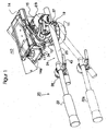
- a camera tripod not shown here, carries a tripod head 10 in a manner known per se - cf. Fig. 1 - Which comprises a stator 11 and a rotatable about an invisible vertical axis rotor 12.
- a camera table 14 On the upper side of the rotor 12 is a camera table 14, which can be tilted about a part 15 about a non-visible horizontal tilt axis NA by about +/- 90 °.
- the camera receiving part 15 of the tripod head carries in the region of the inclination axis NA bearing eye 17 and the rotor 12 of the tripod head carries a coupling pin 19, which form connection points for a pivot arm 20, by means of which the camera to the inclination axis in each desired dimensions by the here also not shown operator can be tilted up or down from the horizontal.
- the camera is used to record a film or video camera, also not shown here.
- the pivot arm 20 - see. also Fig. 2 - Is formed in two parts and comprises a pivoting handle 22 and an adjusting unit 24 to be described, which is surrounded by a pipe section 23.
- the pivoting handle 22 and the adjusting unit 24 are articulated to one another via a lockable and lockable adjusting bearing 25 and with a pivot bearing 31.
- the detection and release of the adjusting bearing 25 is provided with a handle screw 21st
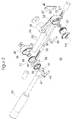
- a parallel crank actuator 24 shows Fig. 2
- the pipe section 23 is provided at its ends with a respective housing 25 and 26, in each of which a gear 27 and 28 of the same diameter and the same module is rotatably mounted.
- the gears 27 and 28 are connected by gearing.
- the drive of the gear 27 via the inclination of the camera table, the output via the gear 28 takes place on the pivot handle 22.
- the housing 25 is connected to the pipe section 23 at an acute angle einlagerender bearing arm 33 which carries a bearing eye 34, through that centrally provided with a handle 35 locking screw 36 protrudes.
- a slotted fork arm 37 is fixedly connected to the housing 25, which in the installed state, the coupling pin 19 - see.
- the housing 26 facing away from the housing 26 on the pipe section 23 has on its one side a receptacle 38 - see.
- Fig. 2 for the adjustment bearing 29, which comprises two facing clamping plates 40, 41, which are penetrated centrally by the handle 43 carrying a locking screw 21.
- the locking screw 21 is arranged coaxially to the axis of rotation of the gear 28, which is in operative connection with the pivoting handle via a pivot bearing 31, as can be seen from Fig. 2 is clearly apparent.
- the pivot handle 22 can be pivoted about said axis and by tightening the locking screw by means of said clamping discs be locked in the assumed position. In this way can be spent by the operator not shown here, the pivoting handle 22 in a favorable ergonomic position for him, regardless of the in Fig. 1 shown position of the swivel arm.
- the transmission of the inclination movement of the camera table on the pivoting handle can also be done in other than the type described, for example by a parallelogram or hydraulically.
Landscapes
- Engineering & Computer Science (AREA)
- General Engineering & Computer Science (AREA)
- Physics & Mathematics (AREA)
- General Physics & Mathematics (AREA)
- Mechanical Engineering (AREA)
- Accessories Of Cameras (AREA)
Description
- Die Erfindung betrifft einen Schwenkarm gemäß dem Oberbegriff des Anspruches 1.
- Bekanntlich umfasst ein solcher Stativkopf einen Stator und einen bezüglich des Stators um eine senkrechte Achse herum drehbar gelagerten Rotor zur Aufnahme des um eine wagerechte Achse neigbaren Kameratisches, auf dem die Film- oder Videokamera montiert ist. Zum Verschwenken des Kameratisches dient mindestens ein dort befestigter Schwenkarm, dessen Schwenklage entsprechend des Neigungswinkels des Kameratisches einen Winkelbereich zwischen +/- 90° umfasst.
- Da Film- und Videokameras Gewichte bis zu 50 kg und mehr aufweisen, treten trotz gewisser Gewichtsausgleichsmaßnahmen am Stativkopf erhebliche ergonomische Probleme an den Schultergelenken, insbesondere aber an den proximalen Handgelenken des die Kamera bedienenden Operators auf. Die maximale Palmarflexion und Dorsalextension beträgt zusammen nur 80°, wobei die Dorsalextension nur maximal 70° beträgt. Hinzu kommen die erheblichen Belastungen der dazu gehörenden Gelenkbänder des Operators.
- Hier Abhilfe bei der Bedienung solcher Film- oder Videokamera mit Hilfe technisch einfacher und kostengünstiger Mittel zu schaffen, ist Aufgabe der Erfindung.
- Diese Aufgabe ist erfindungsgemäß durch die Merkmale des Anspruches 1 gelöst.
- Durch die erfindungsgemäße Unterteilung des Schwenkarmes in einen Schwenkgriff und eine damit getrieblich verbundene Stelleinheit verbleibt der Schwenkgriff zur Bedienung der Film- oder Videokamera unabhängig von der Neigung des Kameratisches stets in der vom Operator einmal ein- und festgestellten Winkellage, was zu einer signifikanten Entlastung der Gelenke und der zugehörigen Bänder des bedienenden Operators führt.
- Die Stelleinheit kann als ein Festglied aufweisendes Parallelkurbelgetriebe mit zwei den gleichen Durchmesser und gleiches Modul aufweisenden Zahnrädern und eine damit kämmende Zahnstange oder damit kämmenden Zahnriemen ausgebildet sein.
- Weitere Merkmale der Erfindung ergeben sich aus den Unteransprüchen.
- Für ein festes Einstellen der Kipplage einer Kamera ist es bekannt, den die Kamera aufnehmenden Tisch an seinem einen Ende schwenkbar mit einer Grundplatte zu verbinden und über ein auf der Grundplatte befindliches, von einer Handkurbel angetriebenes Schraubengetriebe, das über dort verstell- und schwenkbar gelagerte Laschen auf den Tisch einwirkt, zu kippen; vgl.
US 3,603,545 . - Es ist ferner bekannt, eine Konsole zur Aufnahme von Monitoren und ähnlichem über ein von einem mittels Stellknopf bedienbaren Schraubengetriebe, das auf ein Parallelkurbelgestänge wirkt, in der Höhe parallel zu sich selbst zu verstellen; vgl.
US 5,713,549 . - Diese bekannten Anordnungen sind aber zur Lösung der hier vorliegenden Aufgabe zur Entlastung der Gelenke und zugehörigen Bänder des eine Filmkamera bedienenden Operators nicht geeignet.
- Die Erfindung ist nachfolgend an Hand eines in der Zeichnung mehr oder minder schematisch dargestellten Ausführungsbeispieles beschrieben. Es zeigen
- Fig. 1
- eine perspektivische Darstellung eines nur teilweise dargestellten Stativkopfes mit Kameratisch und daran befestigtem zweiteiligem Schwenkarm gemäß der Erfindung und
- Fig. 2
- eine Explosionsdarstellung der in das eine Schwenkarmteil integrierten Stelleinheit
- Ein hier nicht dargestelltes Kamerastativ trägt in an sich bekannter Weise einen Stativkopf 10 - vgl.
Fig. 1 -, der einen Stator 11 sowie einen um eine nicht sichtbare senkrechte Achse drehbaren Rotor 12 umfasst. Auf der Oberseite des Rotors 12 befindet sich ein Kameratisch 14, der über ein Teil 15 um eine nicht sichtbare waagerechte Neigeachse NA um etwa +/- 90° geneigt werden kann. Der den Kameratisch aufnehmende Teil 15 des Stativkopfes trägt im Bereich der Neigungsachse NA ein Lagerauge 17 und der Rotor 12 des Stativkopfes trägt einen Kupplungsstift 19, welche Anschlusspunkte für einen Schwenkarm 20 bilden, mittels dem der Kameratisch um die Neigungsachse in jeweils gewünschtem Ausmaße durch den hier ebenfalls nicht dargestellten Operator nach oben oder unten gegenüber der Waagerechten geneigt werden kann. Der Kameratisch dient der Aufnahme einer hier ebenfalls nicht dargestellten Film- oder Videokamera. - Der Schwenkarm 20 - vgl. auch
Fig. 2 - ist zweiteilig ausgebildet und umfasst einen Schwenkgriff 22 und eine noch zu beschreibende Stelleinheit 24, die von einem Rohrstück 23 umfasst ist. Der Schwenkgriff 22 und die Stelleinheit 24 sind über ein ein- und feststellbares Einstelllager 25 sowie mit einem Schwenklager 31 miteinander gelenkig verbunden. Dem Feststellen und dem Lösen des Einstelllagers 25 dient eine mit einem Handgriff versehene Schraube 21. - Der Aufbau und die Anordnung der hier als Parallelkurbeltrieb ausgebildeten Stelleinheit 24 zeigt
Fig. 2 . Hierzu ist das Rohrstück 23 an seinen Enden mit je einem Gehäuse 25 und 26 versehen, in denen je ein Zahnrad 27 und 28 gleichen Durchmessers und gleichen Moduls drehbar gelagert ist. Mittels einer im Rohrstück 23 gleitenden Zahnstange 30 sind die Zahnräder 27 und 28 getrieblich miteinander verbunden. Der Antrieb des Zahnrades 27 erfolgt über die Neigung des Kameratisches, der Abtrieb über das Zahnrad 28 erfolgt auf den Schwenkgriff 22. Mit dem Gehäuse 25 ist ein mit dem Rohrstück 23 einen spitzen Winkel einschließender Lagerarm 33 verbunden, der ein Lagerauge 34 trägt, durch dass mittig eine mit einem Handgriff 35 versehene Feststellschraube 36 ragt. Ferner ist ein geschlitzter Gabelarm 37 mit dem Gehäuse 25 fest verbunden, der im eingebauten Zustand den Kupplungsstift 19 - vgl.Fig. 1 - umfasst und somit das Gehäuse 25 des beschriebenen Parallelkurbelgetriebes als Festglied definiert. - Das dem Gehäuse 25 abgewandte Gehäuse 26 an dem Rohrstück 23 weist an seiner einen Seite eine Aufnahme 38 - vgl.
Fig. 2 -für das Einstelllager 29 auf, welches zwei einander zugewandte Klemmscheiben 40, 41 umfasst, die von der einen Handgriff 43 tragenden Feststellschraube 21 mittig durchsetzt sind. Die Feststellschraube 21 ist gleichachsig zur Drehachse des Zahnrades 28 angeordnet, das mit dem Schwenkgriff über ein Schwenklager 31 in getrieblicher Wirkverbindung steht, wie dies ausFig. 2 klar ersichtlich ist. Nach Lösen der Feststellschraube 21 kann der Schwenkgriff 22 um die genannte Achse verschwenkt und durch Anziehen der Feststellschraube mittels der genannten Klemmscheiben in der eingenommenen Lage arretiert werden. Auf diese Weise kann durch den hier nicht dargestellten Operator der Schwenkgriff 22 in eine für ihn günstige ergonomische Lage verbracht werden, und zwar unabhängig von der inFig. 1 dargestellten Lage des Schwenkarmes. - Befinden sich die im Zusammenhang mit
Fig. 2 beschriebenen Bauteile in der inFig. 1 dargestellten Ausgangslage mit dem Kameratisch 14 - mit diesem also über das Lagerauge 34 fest verbunden sowie der Gabelarm 37 in Eingriff mit dem Kupplungsstift 19 - so bewirken über den Schwenkarm 20 erzeugte Neigungen des Kameratisches 14 eine Drehbewegung des Zahnrades 27, die über die Zahnstange 30 auf das Zahnrad 28 drehwinkelsynchron übertragen werden, so dass der mit dem Zahnrad 28 über das Schwenklager 31 drehfest verbundene Schwenkgriff 22 unabhängig von der Neigung des Schwenkarmes, also der Stelleinheit 24, seine über das Schwenklager 31 eingestellte Winkellage beibehält, wie dies durch die gestrichelt dargestellte Schwenkgrifflage 22a inFig. 1 dargestellt ist. - Auf diese Weise ist die gewünschte ergonomisch günstige Einstellung der Neigung der nicht dargestellten Kamera für den Operator auf verblüffend einfache Weise erzielt.
- Die Übertragung der Neigungsbewegung des Kameratisches auf den Schwenkgriff kann auch auf andere als die beschriebene Art erfolgen, zum Beispiel durch ein Parallelogrammgestänge oder auch hydraulisch.
-
- 10
- Stativkopf
- 11
- Stator
- 12
- Rotor des Stativkopfes
- 14
- Kameratisch
- 15
- den Kameratisch aufnehmender Teil des Stativkopfes
- 17
- Lagerauge
- 19
- Kupplungsstift
- 20
- Schwenkarm
- 21
- Feststellschraube
- 22
- Schwenkgriff
- 22a
- Schwenkgrifflage
- 23
- Rohrstück
- 24
- Stelleinheit
- 25
- Gehäuse
- 26
- Gehäuse
- 27
- Zahnrad
- 28
- Zahnrad
- 29
- Einstelllager
- 30
- Zahnstange
- 31
- Schwenklager
- 33
- Lagerarm
- 34
- Lagerauge an Gehäuse 25
- 35
- Handgriff
- 36
- Feststellschraube
- 37
- Gabelarm
- 38
- Aufnahme für Einstelllager 29
- 41
- Klemmscheibe
- 42
- Klemmscheibe
- 43
- Handgriff für Feststellschraube 21
Claims (6)
- Schwenkarm (20) für den Kameratisch (14) eines Stativkopfes zur Aufnahme einer Film- oder Videokamera, insbesondere zum Neigen der Kamera nach oben oder unten gegenüber einer Wagerechten, wobei der Schwenkarm (20) einen Schwenkgriff (22) und eine Stelleinheit (24) umfasst, die ein mit dem Kameratisch (14) verbundenes antreibendes Glied (27) und ein mit dem Schwenkgriff (22) verbundenes abtreibendes Glied (28) aufweist, dadurch gekennzeichnet, dass die Glieder als miteinander in Wirkverbindung stehende Teile eines Parallelkurbeltriebes derart ausgebildet sind, dass über die Stelleinheit (24) eine gewählte Einstelllage des Schwenkgriffes (22) unabhängig von der Größe des jeweiligen über den Schwenkarm (20) eingestellten Neigungswinkels (α) des Kameratisches (14) beibehalten ist.
- Schwenkarm nach Patentanspruch 1, dadurch gekennzeichnet, dass der Parallelkurbeltrieb der Stelleinheit (24) zwei den gleichen Durchmesser und gleichen Modul aufweisende Zahnräder (27, 28) sowie eine damit kämmende Zahnstange (30) aufweist, die von einem Rohrstück (23) umfasst ist, das an seinen Stirnseiten die Zahnräder (27, 28) aufnehmende Gehäuse (25, 26) trägt, zu denen das ein Gehäuse (25) als Festglied des Parallelkurbeltriebes dient.
- Schwenkarm nach dem Patentanspruch 1,
dadurch gekennzeichnet, dass das Parallelkurbelgetriebe der Stelleinheit (24) zwei Zahnräder (27, 28) gleichen Durchmesser und gleichen Modul und einen damit in Eingriff stehende als Kettentrieb wirkenden Zahnriemen umfasst. - Schwenkarm nach den Patentansprüchen 2 oder 3,
dadurch gekennzeichnet, dass dem als Festglied des Parallelkurbelgetriebes dienenden Gehäuse (25) ein Gabelarm (37) zugeordnet ist, der einen am starren Teil (12) des Stativkopfes (10) befindlichen Stift (19) umfasst. - Schwenkarm nach einem der vorhergehenden Patentansprüche 2-4, dadurch gekennzeichnet, dass das Rohrstück (23) je ein Gehäuse (25, 26) zur Aufnahme je eines der Zahnräder (27, 28) trägt, von denen das eine Ende des einen Gehäuses (25) ein dem Verbinden mit dem Kameratisch (14) im Bereich der Neigungsachse (NA) dienendes, an einem mit dem Rohrstück (23) fest verbundenen Lagerarm (33) befestigtes Lagerauge (34) aufweist, während das andere Gehäuse (26) sowohl das die jeweils gewählte Voreinstellung der Schwenklage des Schwenkgriffes (22) fixierende Einstelllager (29) als auch das Schwenklager (31) trägt.
- Schwenkarm nach Patentanspruch 5, dadurch gekennzeichnet, dass der das Lagerauge (34) tragende Lagerarm (33) mit dem den Zahnstangentrieb (27, 28, 30) umfassenden Rohrstück (23) einen spitzen Winkel einschließt.
Applications Claiming Priority (1)
| Application Number | Priority Date | Filing Date | Title |
|---|---|---|---|
| DE202006012998U DE202006012998U1 (de) | 2006-08-24 | 2006-08-24 | Schwenkarm für den Kameratisch eines Stativkopfes zur Aufnahme einer Film- oder Videokamera |
Publications (3)
| Publication Number | Publication Date |
|---|---|
| EP1892455A2 EP1892455A2 (de) | 2008-02-27 |
| EP1892455A3 EP1892455A3 (de) | 2008-04-30 |
| EP1892455B1 true EP1892455B1 (de) | 2010-12-01 |
Family
ID=37296032
Family Applications (1)
| Application Number | Title | Priority Date | Filing Date |
|---|---|---|---|
| EP07113030A Ceased EP1892455B1 (de) | 2006-08-24 | 2007-07-24 | Schwenkarm für den Kameratisch eines Stativkopfes zur Aufnahme einer Film- oder Videokamera |
Country Status (2)
| Country | Link |
|---|---|
| EP (1) | EP1892455B1 (de) |
| DE (2) | DE202006012998U1 (de) |
Family Cites Families (7)
| Publication number | Priority date | Publication date | Assignee | Title |
|---|---|---|---|---|
| GB1299882A (en) * | 1969-01-24 | 1972-12-13 | Ernest F Moy Ltd | Tilt table device |
| US3822769A (en) * | 1972-09-27 | 1974-07-09 | Connor C O | Panhead drag mechanism |
| DE4024585C2 (de) * | 1990-08-02 | 1995-04-20 | Kuerbi & Niggeloh Bilora Gmbh | Kugelgelenkkopf für fotografische Stative |
| US5037053A (en) * | 1990-08-23 | 1991-08-06 | Midmark Corporation | Support arm for optical accessories |
| US5713549A (en) * | 1995-05-22 | 1998-02-03 | Shieh; En-Ru | Monitor support device |
| US5853153A (en) * | 1997-04-08 | 1998-12-29 | Condrey; Robert L. | Camera float device |
| FR2878016B1 (fr) * | 2004-11-15 | 2007-02-09 | Hawking Technology Sa | Dispositif de maintien d'horizontalite d'un support a debattement vertical |
-
2006
- 2006-08-24 DE DE202006012998U patent/DE202006012998U1/de not_active Expired - Lifetime
-
2007
- 2007-07-24 EP EP07113030A patent/EP1892455B1/de not_active Ceased
- 2007-07-24 DE DE502007005817T patent/DE502007005817D1/de active Active
Also Published As
| Publication number | Publication date |
|---|---|
| DE502007005817D1 (de) | 2011-01-13 |
| EP1892455A3 (de) | 2008-04-30 |
| DE202006012998U1 (de) | 2006-10-12 |
| EP1892455A2 (de) | 2008-02-27 |
Similar Documents
| Publication | Publication Date | Title |
|---|---|---|
| DE3036852C2 (de) | Vorrichtung zum Aufstellen eines Datensichtgerätes auf einer Arbeitsfläche | |
| EP2303496B1 (de) | Handhubsägemaschine | |
| EP2815681B1 (de) | Verstellmechanik zur verstellung von beweglichen möbelteilen | |
| DE4245034C2 (de) | Stativ für Operationsmikroskop mit Drehmomentausgleich | |
| WO2019048514A1 (de) | Vorrichtung aufweisend einen grundträger und einen geräteträger | |
| DE102010041466B4 (de) | Vorrichtung zum Positionieren eines Werkstücks | |
| EP2243456B1 (de) | Operationstisch | |
| EP1235965A1 (de) | Verteilermast für betonpumpen | |
| EP1788299B1 (de) | Halterung für ein optisches Gerät | |
| EP0843605B1 (de) | Vorrichtung zum biegen eines bleches | |
| DE10046670B4 (de) | Basisanordnung für ein Videoanzeigegerät | |
| DE19742050B4 (de) | Stativ mit Gewichtsausgleich | |
| EP1892455B1 (de) | Schwenkarm für den Kameratisch eines Stativkopfes zur Aufnahme einer Film- oder Videokamera | |
| DE10136341A1 (de) | Balancesystem mit Rollgriff für handgefütterte Kameras | |
| DE69420617T2 (de) | Fensterbedienungsvorrichtung mit Gewichtsausgleich | |
| DE202015100109U1 (de) | Schneidvorrichtung | |
| DE202010005251U1 (de) | Neigungseinstellmechanismus für einen Bogengeradstoßer | |
| DE3423630C2 (de) | ||
| WO2010028828A1 (de) | Kapp- und gehrungssäge mit einer winkelfixiereinrichtung | |
| AT396491B (de) | Einrichtung zur lösbaren befestigung eines arbeitsgerätes an einem fahrzeug | |
| EP4007862B1 (de) | Riemen-spanneinrichtung | |
| DE10353004B4 (de) | Stativkopf | |
| DE3921711C1 (de) | ||
| DE4419509C2 (de) | Maschinengestell mit Hubeinrichtung | |
| EP1440777B1 (de) | Kettensäge |
Legal Events
| Date | Code | Title | Description |
|---|---|---|---|
| PUAI | Public reference made under article 153(3) epc to a published international application that has entered the european phase |
Free format text: ORIGINAL CODE: 0009012 |
|
| AK | Designated contracting states |
Kind code of ref document: A2 Designated state(s): AT BE BG CH CY CZ DE DK EE ES FI FR GB GR HU IE IS IT LI LT LU LV MC MT NL PL PT RO SE SI SK TR |
|
| AX | Request for extension of the european patent |
Extension state: AL BA HR MK YU |
|
| PUAL | Search report despatched |
Free format text: ORIGINAL CODE: 0009013 |
|
| AK | Designated contracting states |
Kind code of ref document: A3 Designated state(s): AT BE BG CH CY CZ DE DK EE ES FI FR GB GR HU IE IS IT LI LT LU LV MC MT NL PL PT RO SE SI SK TR |
|
| AX | Request for extension of the european patent |
Extension state: AL BA HR MK RS |
|
| 17P | Request for examination filed |
Effective date: 20080811 |
|
| AKX | Designation fees paid |
Designated state(s): DE GB IT |
|
| GRAP | Despatch of communication of intention to grant a patent |
Free format text: ORIGINAL CODE: EPIDOSNIGR1 |
|
| GRAS | Grant fee paid |
Free format text: ORIGINAL CODE: EPIDOSNIGR3 |
|
| GRAA | (expected) grant |
Free format text: ORIGINAL CODE: 0009210 |
|
| AK | Designated contracting states |
Kind code of ref document: B1 Designated state(s): DE GB IT |
|
| REG | Reference to a national code |
Ref country code: GB Ref legal event code: FG4D Free format text: NOT ENGLISH |
|
| REF | Corresponds to: |
Ref document number: 502007005817 Country of ref document: DE Date of ref document: 20110113 Kind code of ref document: P |
|
| PLBE | No opposition filed within time limit |
Free format text: ORIGINAL CODE: 0009261 |
|
| STAA | Information on the status of an ep patent application or granted ep patent |
Free format text: STATUS: NO OPPOSITION FILED WITHIN TIME LIMIT |
|
| 26N | No opposition filed |
Effective date: 20110902 |
|
| REG | Reference to a national code |
Ref country code: DE Ref legal event code: R097 Ref document number: 502007005817 Country of ref document: DE Effective date: 20110902 |
|
| PGFP | Annual fee paid to national office [announced via postgrant information from national office to epo] |
Ref country code: GB Payment date: 20140730 Year of fee payment: 8 |
|
| GBPC | Gb: european patent ceased through non-payment of renewal fee |
Effective date: 20150724 |
|
| PG25 | Lapsed in a contracting state [announced via postgrant information from national office to epo] |
Ref country code: GB Free format text: LAPSE BECAUSE OF NON-PAYMENT OF DUE FEES Effective date: 20150724 |
|
| PGFP | Annual fee paid to national office [announced via postgrant information from national office to epo] |
Ref country code: DE Payment date: 20200615 Year of fee payment: 14 |
|
| PGFP | Annual fee paid to national office [announced via postgrant information from national office to epo] |
Ref country code: IT Payment date: 20200731 Year of fee payment: 14 |
|
| REG | Reference to a national code |
Ref country code: DE Ref legal event code: R119 Ref document number: 502007005817 Country of ref document: DE |
|
| PG25 | Lapsed in a contracting state [announced via postgrant information from national office to epo] |
Ref country code: DE Free format text: LAPSE BECAUSE OF NON-PAYMENT OF DUE FEES Effective date: 20220201 |
|
| PG25 | Lapsed in a contracting state [announced via postgrant information from national office to epo] |
Ref country code: IT Free format text: LAPSE BECAUSE OF NON-PAYMENT OF DUE FEES Effective date: 20210724 |