EP1892441B1 - Cylinder head seal - Google Patents
Cylinder head seal Download PDFInfo
- Publication number
- EP1892441B1 EP1892441B1 EP07015424.0A EP07015424A EP1892441B1 EP 1892441 B1 EP1892441 B1 EP 1892441B1 EP 07015424 A EP07015424 A EP 07015424A EP 1892441 B1 EP1892441 B1 EP 1892441B1
- Authority
- EP
- European Patent Office
- Prior art keywords
- sheet metal
- cylinder head
- combustion chamber
- head gasket
- metal layer
- Prior art date
- Legal status (The legal status is an assumption and is not a legal conclusion. Google has not performed a legal analysis and makes no representation as to the accuracy of the status listed.)
- Active
Links
- 239000002184 metal Substances 0.000 claims description 102
- 238000002485 combustion reaction Methods 0.000 claims description 54
- 238000007789 sealing Methods 0.000 claims description 32
- 238000003466 welding Methods 0.000 claims description 11
- 239000000126 substance Substances 0.000 claims 1
- 239000010410 layer Substances 0.000 description 22
- 239000011324 bead Substances 0.000 description 19
- 230000006378 damage Effects 0.000 description 5
- 238000004049 embossing Methods 0.000 description 3
- 239000002356 single layer Substances 0.000 description 3
- 239000012530 fluid Substances 0.000 description 2
- 239000000463 material Substances 0.000 description 2
- 239000003795 chemical substances by application Substances 0.000 description 1
- 238000000576 coating method Methods 0.000 description 1
- 230000006835 compression Effects 0.000 description 1
- 238000007906 compression Methods 0.000 description 1
- 239000000498 cooling water Substances 0.000 description 1
- 238000009434 installation Methods 0.000 description 1
- 239000007788 liquid Substances 0.000 description 1
- 239000010687 lubricating oil Substances 0.000 description 1
- 238000000034 method Methods 0.000 description 1
- 230000033764 rhythmic process Effects 0.000 description 1
- 230000001020 rhythmical effect Effects 0.000 description 1
- 239000002699 waste material Substances 0.000 description 1
Images
Classifications
-
- F—MECHANICAL ENGINEERING; LIGHTING; HEATING; WEAPONS; BLASTING
- F16—ENGINEERING ELEMENTS AND UNITS; GENERAL MEASURES FOR PRODUCING AND MAINTAINING EFFECTIVE FUNCTIONING OF MACHINES OR INSTALLATIONS; THERMAL INSULATION IN GENERAL
- F16J—PISTONS; CYLINDERS; SEALINGS
- F16J15/00—Sealings
- F16J15/02—Sealings between relatively-stationary surfaces
- F16J15/06—Sealings between relatively-stationary surfaces with solid packing compressed between sealing surfaces
- F16J15/08—Sealings between relatively-stationary surfaces with solid packing compressed between sealing surfaces with exclusively metal packing
- F16J15/0818—Flat gaskets
-
- F—MECHANICAL ENGINEERING; LIGHTING; HEATING; WEAPONS; BLASTING
- F02—COMBUSTION ENGINES; HOT-GAS OR COMBUSTION-PRODUCT ENGINE PLANTS
- F02F—CYLINDERS, PISTONS OR CASINGS, FOR COMBUSTION ENGINES; ARRANGEMENTS OF SEALINGS IN COMBUSTION ENGINES
- F02F11/00—Arrangements of sealings in combustion engines
- F02F11/002—Arrangements of sealings in combustion engines involving cylinder heads
-
- F—MECHANICAL ENGINEERING; LIGHTING; HEATING; WEAPONS; BLASTING
- F16—ENGINEERING ELEMENTS AND UNITS; GENERAL MEASURES FOR PRODUCING AND MAINTAINING EFFECTIVE FUNCTIONING OF MACHINES OR INSTALLATIONS; THERMAL INSULATION IN GENERAL
- F16J—PISTONS; CYLINDERS; SEALINGS
- F16J15/00—Sealings
- F16J15/02—Sealings between relatively-stationary surfaces
- F16J15/06—Sealings between relatively-stationary surfaces with solid packing compressed between sealing surfaces
- F16J15/08—Sealings between relatively-stationary surfaces with solid packing compressed between sealing surfaces with exclusively metal packing
- F16J15/0818—Flat gaskets
- F16J2015/0862—Flat gaskets with a bore ring
Definitions
- the invention relates to a cylinder head gasket for a multi-cylinder engine, in particular for a commercial vehicle diesel engine, which has a single-layer sealing plate with a single sheet metal layer, combustion chamber openings and for each combustion chamber opening at least one annular combustion chamber sealing element which surrounds the associated combustion chamber opening and has the shape of a arranged on the sheet metal layer and materially connected thereto by welding metal sheet ring.
- the present invention relates to such cylinder head gaskets in which is sealed around a combustion chamber opening around only with a metal ring, so that it forms the single combustion chamber sealing element.
- cylinder head gaskets of the type mentioned are designed as flat rings metal rings on that side of the sheet metal layer (usually and hereinafter referred to as support plate), which is facing the cylinder head with built-in seal.
- the sheet metal rings are connected to the carrier sheet, which is flat under the sheet metal rings, by welding, namely by spot welding or by means of continuous welds.
- the material of the welds or welds used to fasten the sheet metal rings frequently overhangs the metal rings, albeit only slightly, and secondly, the material melted during welding and then solidifies "Welding cores" which, when the cylinder head gasket is mounted and pressed, are subjected to high compressive forces and thereby pressed towards the inside of the carrier sheet.
- a cylinder head gasket for a multi-cylinder engine which has a single-layer gasket plate with a single, over the entire gasket plate extending sheet metal layer, combustion chamber openings and for each combustion chamber opening on each side of the sheet metal layer, an annular combustion chamber sealing element, the associated combustion chamber Opening surrounds and has the shape of a arranged on the sheet metal layer and directly connected thereto by welding metal sheet ring, wherein the metal sheet rings are the only Form combustion chamber sealing elements.
- this known cylinder head gasket all metal sheet rings and the sheet metal layer are flat overall.
- the sealing plate has a single, over the entire gasket plate extending sheet metal layer and for each combustion chamber opening a surrounding this metal sheet ring, which is connected to the sheet metal layer, however, via a likewise annular plastic layer.
- Fig. 1 is sealed around each combustion chamber opening by means of a provided in the sheet metal layer bead, for which the sheet metal ring forms a deformation limiter, that is, a so-called stopper.
- the DE-A-100 21 975 leaves open whether the metal sheet rings with built-in cylinder head gasket on the cylinder head or the engine block facing side of the sheet metal layer.
- a cylinder head gasket for a multi-cylinder engine having a gasket plate with a single metal sheet layer extending over the entire gasket plate provided around each combustion chamber opening with a bead for sealing the latter and molded into the metal sheet layer.
- Each of these beads is assigned to a fixed metal sheet metal sheet ring, which is to protect the bead from excessive flattening, that forms a so-called stopper.
- the sheet metal rings are sealed to the engine block facing side of the sheet metal layer around the combustion chamber openings around but sealed with the beads, which the sheet metal rings as deformation limiter, that is assigned as so-called stopper are.
- the cylinder head gasket disclosed a single-layered gasket sheet having a single sheet metal sheet provided with a bead formed in the sheet metal sheet for sealing around each combustion chamber opening.
- a metal sheet ring is secured on the sheet metal layer between each combustion chamber opening and the sealing bead serving to protect the bead from excessive deformation, that forms a stopper for the bead.
- the invention relates to a cylinder head gasket for a multi-cylinder engine, in particular for a high density commercial vehicle diesel engine having a single-layer gasket with a single sheet metal layer, combustion chamber openings and for each combustion chamber opening at least one annular combustion chamber sealing element, the associated combustion chamber And encloses the shape of a arranged on the sheet metal layer and materially connected thereto by welding metal sheet ring, wherein the metal sheet rings form the only combustion chamber sealing elements.
- the metal sheet rings provided with a height profile varies the height of such a sheet metal ring around the combustion chamber opening associated therewith, and according to claim 1 provided around the combustion chamber openings around height profiles are designed so that they with built-in cylinder head gasket the Waste of bolt forces with increasing distance from the cylinder head bolts and the locally varying component stiffness account.
- the metal sheet rings form the only combustion chamber sealing elements, which means that the cylinder head gasket around the combustion chamber openings for their sealing has no beads and the metal sheet rings and the sheet metal rings adjacent, ie covered by the latter areas of the sheet metal layer, apart are at least substantially planar from the height profiles, at least in the vicinity of the combustion chamber openings.
- the inventors are based on the consideration that the above-described sliding movements at least substantially only take place between the cylinder head gasket and the sealing surface of the cylinder head, even if far smaller sliding movements can also take place between the cylinder head gasket and the sealing surface of the engine block.
- the invention proposes to install all the metal rings on the cylinder block with the installed side facing the engine block side of the sheet metal layer (the support plate).
- the carrier plate has combustion chamber openings and fluid openings for the passage of liquid media, such as cooling water and lubricating oil. At the edges of the fluid openings annular elastomeric sealing elements are molded onto the support plate.
- each combustion chamber opening around this known cylinder head gasket is provided with a combustion chamber sealing element in the form of a sheet metal ring arranged on the support plate; adjacent to the combustion chamber opening, the support plate and the sheet metal ring each have a flat, annular edge region, connect to the radially outwardly interlocking full corrugations of the support plate and the sheet metal ring, wherein the carrier sheet facing convex side of the sheet metal ring bead in the concave side the carrier sheet bead engages.
- this known cylinder head gasket belongs to a different type of seal than the improved by the present invention type of seal, because in this known cylinder head gasket is sealed around the combustion chamber opening mainly by the full corrugations of the support plate and the sheet metal ring, while the cylinder head gasket according to the invention in the region of the sheet metal ring is without beads and seals in the immediate vicinity of the combustion chamber opening around it by the fact that during installation of the cylinder head gasket by the cylinder head bolts the thickened by the sheet metal ring ring portion of the sealing plate is clamped with particularly high pressure forces between the engine block and the cylinder head.
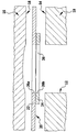
- FIG. 1 shows a section through a combustion chamber opening having a region of the cylinder head gasket and the built-in cylinder head gasket of these adjacent areas of the engine block and the cylinder head, to improve the clarity of illustration, the various components were drawn at a distance from each other and the dimensions of the support plate and the metal ring were not reproduced to scale.
- the drawing shows an engine block 10 with a combustion chamber 12 and an engine block sealing surface 14, a cylinder head 16 with a cylinder head sealing surface 18 and a cylinder head gasket 20 (all only partially).
- the illustrated embodiment of the cylinder head gasket has a flat support plate 22 and - as shown - a sheet metal ring 24.
- the cylinder head gasket 20 has a designated as a whole 26 combustion chamber opening, which from an opening 26a in the support plate 22 and the opening 26b the sheet metal ring 24 is formed.
- the cylinder head gasket according to the invention need not be purely metallic and may be provided with one or more in particular elastomeric coatings and / or inserts, which were not shown in the drawing.
- the metal sheet ring 24 is substantially thinner than the carrier sheet 22 and is mounted on that side of the carrier sheet 22 which, when the cylinder head gasket is installed, faces the engine block 10.
- the sheet metal ring 24 may, as already mentioned, be connected to the carrier plate 22 by spot welding or by means of a continuous weld.
- the lower side of the sheet metal ring 24 according to the drawing can be provided with the above-described height profile, which is produced by embossing.
- the sheet metal ring 24 adjacent portion of the support plate 22 is provided with a height profile, before the sheet metal ring 24 secured to the support plate 22, said height profile provided on the side facing away from the sheet metal ring 24 of the support plate 22 should be.
- the sheet metal ring 24 directly adjoins the combustion chamber opening 26, although in principle it could have an opening 26b whose diameter is slightly larger than the diameter of the combustion chamber 12.
- the cylinder head gasket for sealing around a combustion chamber opening around several combustion chamber sealing elements although this is not desirable for cost reasons.
- the sheet metal rings are very thin - their thickness is between 0.05 mm and 0.40 mm, preferably of the order of 0.25 mm.
- the support plate is much thicker and has a thickness of up to 1.10 mm, preferably of about 0.40 mm.
Description
Die Erfindung betrifft eine Zylinderkopfdichtung für einen Mehrzylindermotor, insbesondere für einen Nutzfahrzeug-Dieselmotor, welche eine einlagige Dichtungsplatte mit einer einzigen Metallblechlage, Brennraum-Öffnungen sowie für jede Brennraum-Öffnung mindestens ein ringförmiges Brennraum-Dichtelement aufweist, das die zugeordnete Brennraum-Öffnung umschließt und die Gestalt eines auf der Metallblechlage angeordneten und mit dieser durch Schweißen stoffschlüssig verbundenen Metallblechrings hat.The invention relates to a cylinder head gasket for a multi-cylinder engine, in particular for a commercial vehicle diesel engine, which has a single-layer sealing plate with a single sheet metal layer, combustion chamber openings and for each combustion chamber opening at least one annular combustion chamber sealing element which surrounds the associated combustion chamber opening and has the shape of a arranged on the sheet metal layer and materially connected thereto by welding metal sheet ring.
Wenn bei einer solchen Zylinderkopfdichtung für die Abdichtung um eine Brennraum-Öffnung herum außerhalb des Metallblechrings eine höhenelastische Sicke in der Metallblechlage vorgesehen ist, hat der erwähnte Blechring auch die Funktion eines sogenannten Stoppers, welcher eine übermäßige Abflachung der Abdichtsicke beim Einbau der Zylinderkopfdichtung und im Motorbetrieb verhindert; die vorliegende Erfindung betrifft jedoch solche Zylinderkopfdichtungen, bei denen um eine Brennraum-Öffnung herum nur mit einem Blechring abgedichtet wird, so dass dieser das einzige Brennraum-Dichtelement bildet.If in such a cylinder head gasket for sealing around a combustion chamber opening outside of the sheet metal ring, a height elastic bead is provided in the sheet metal layer, said sheet metal ring also has the function of a so-called stopper, which excessive flattening of the sealing bead when installing the cylinder head gasket and engine operation prevented; However, the present invention relates to such cylinder head gaskets in which is sealed around a combustion chamber opening around only with a metal ring, so that it forms the single combustion chamber sealing element.
Bei bekannten Zylinderkopfdichtungen der eingangs erwähnten Art sind als ebene Ringe gestaltete Blechringe auf derjenigen Seite der Metallblechlage (üblicherweise und im Folgenden Trägerblech genannt) angeordnet, welche bei eingebauter Dichtung dem Zylinderkopf zugekehrt ist. Die Blechringe sind mit dem Trägerblech, welches unter den Blechringen eben ist, durch Schweißen, nämlich durch Punktschweißen oder mittels kontinuierlicher Schweißnähte, verbunden.In known cylinder head gaskets of the type mentioned are designed as flat rings metal rings on that side of the sheet metal layer (usually and hereinafter referred to as support plate), which is facing the cylinder head with built-in seal. The sheet metal rings are connected to the carrier sheet, which is flat under the sheet metal rings, by welding, namely by spot welding or by means of continuous welds.
Infolge der Tendenz, Hubkolben-Verbrennungsmotoren mit immer höherer Verdichtung zu konstruieren, kommt dem folgenden Problem eine immer größere Bedeutung zu: Infolge der im Motorbetrieb auftretenden wechselnden Gasdrücke wird der Zylinderkopf und seine dem Motorblock zugewandte Dichtfläche im Rhythmus der Zündungen periodisch nach oben, d. h. weg vom Motorblock, ausgewölbt, was zu rhythmischen Schiebebewegungen zwischen der Zylinderkopf-Dichtfläche und der Zylinderkopfdichtung führt - als Schiebebewegungen werden solche Relativbewegungen bezeichnet, welche in der Ebene des sogenannten Dichtspalts zwischen den Dichtflächen von Zylinderkopf und Motorblock ablaufen. Es hat sich nun gezeigt, dass bei den vorstehend beschriebenen bekannten Zylinderkopfdichtungen diese erhöhten Schiebebewegungen zu einer Zerstörung der Schweißverbindungen, vor allem aber der Blechringe selbst führen können - im letztgenannten Fall bleibt ein dem Trägerblech zugewandter Teil eines Blechrings am Trägerblech haften, während zumindest im Bereich von Segmenten des Blechrings obere Teile des Blechrings abgespalten werden, was in der Folge auch zu radialen Brüchen im Blechring führen kann. In jedem Fall ist dann die Abdichtung um die betreffende Brennraum-Öffnung herum nicht mehr gewährleistet.Due to the tendency to design reciprocating internal combustion engines with ever higher compression, the following problem is becoming increasingly important: As a result of changing gas pressures occurring during engine operation, the cylinder head and its sealing surface facing the engine block periodically move upwards, ie away, to the rhythm of the ignitions from the engine block, bulging, which leads to rhythmic sliding movements between the cylinder head sealing surface and the cylinder head gasket - as sliding movements such relative movements are referred to, which run in the plane of the so-called sealing gap between the sealing surfaces of the cylinder head and engine block. It has been shown that in the known cylinder head gaskets described above, these increased sliding movements can lead to destruction of the welded joints, but above all the sheet metal rings themselves - in the latter case a part of a sheet metal ring facing the carrier sheet adheres to the support sheet, while at least in the area of segments of the sheet metal ring upper parts of the sheet metal ring are split off, which can also lead to radial fractures in the sheet metal ring in the sequence. In any case, then the seal around the relevant combustion chamber opening is no longer guaranteed.
Im Zusammenhang mit dem vorstehend erörterten Zerstörungsrisiko ist noch auf folgendes hinzuweisen: Zum einen überragt das Material der der Befestigung der Blechringe dienenden Schweißpunkte bzw. Schweißnähte häufig die Blechringe, wenn auch nur geringfügig, und zum anderen bildet das beim Schweißen aufgeschmolzene und dann erstarrte Material harte "Schweißkerne", die, wenn die Zylinderkopfdichtung montiert ist und gepresst wird, hohen Druckkräften ausgesetzt sind und dadurch in Richtung auf das Innere des Trägerblechs gepresst werden. Schon dabei kann es zu einer Vorschädigung der Zylinderkopfdichtung an den Grenzflächen zwischen den Schweißkernen und den Blechringen kommen, und diese Vorschädigung erhöht noch die Gefahr einer Zerstörung der Schweißverbindungen und/oder der Blechringe, wenn die Letzteren bei eingebauter Zylinderkopfdichtung gegen den Zylinderkopf angepresst und im Motorbetrieb den Schiebebewegungen zwischen der Zylinderkopf-Dichtfläche und der Zylinderkopfdichtung ausgesetzt sind.In connection with the destruction risk discussed above, the following should be noted: First, the material of the welds or welds used to fasten the sheet metal rings frequently overhangs the metal rings, albeit only slightly, and secondly, the material melted during welding and then solidifies "Welding cores" which, when the cylinder head gasket is mounted and pressed, are subjected to high compressive forces and thereby pressed towards the inside of the carrier sheet. Even this can lead to a pre-damage of the cylinder head gasket at the interfaces between the weld cores and the metal rings, and this pre-damage increases the risk of destroying the welded joints and / or the metal rings, when the latter pressed with built-in cylinder head gasket against the cylinder head and engine operation the sliding movements between the cylinder head sealing surface and the cylinder head gasket are exposed.
Die dem Einspannen einer Zylinderkopfdichtung zwischen den Dichtflächen von Motorblock und Zylinderkopf dienenden Pressungskräfte werden durch die Zylinderkopfschrauben punktuell aufgebracht; deshalb, und weil die Motorbauteile Motorblock und Zylinderkopf nicht als absolut starre Bauteile betrachtet werden können, sondern eine örtlich unterschiedliche Bauteilsteifigkeit aufweisen, sind ohne besondere Maßnahmen die auf die eingebaute Zylinderkopfdichtung einwirkenden Pressungskräfte nicht überall dieselben.The clamping forces acting on the clamping of a cylinder head gasket between the sealing surfaces of the engine block and cylinder head are selectively applied by the cylinder head bolts; Therefore, and because the engine components engine block and cylinder head can not be considered as absolutely rigid components, but have a locally different component stiffness, without special measures, the forces acting on the built-in cylinder head gasket pressure forces are not the same everywhere.
Aus der
Auch aus der
Ausweislich der
Aus der
Ebenso wie bei der sich aus der
Gegenstand der Erfindung ist eine Zylinderkopfdichtung für einen Mehrzylindermotor, und zwar insbesondere für einen hochverdichteten Nutzfahrzeug-Dieselmotor, welche eine einlagige Dichtungsplatte mit einer einzigen Metallblechlage, Brennraum-Öffnungen sowie für jede Brennraum-Öffnung mindestens ein ringförmiges Brennraum-Dichtelement aufweist, das die zugeordnete Brennraum-Öffnung umschließt und die Gestalt eines auf der Metallblechlage angeordneten und mit dieser durch Schweißen stoffschlüssig verbundenen Metallblechrings hat, wobei die Metallblechringe die einzigen Brennraum-Dichtelemente bilden.The invention relates to a cylinder head gasket for a multi-cylinder engine, in particular for a high density commercial vehicle diesel engine having a single-layer gasket with a single sheet metal layer, combustion chamber openings and for each combustion chamber opening at least one annular combustion chamber sealing element, the associated combustion chamber And encloses the shape of a arranged on the sheet metal layer and materially connected thereto by welding metal sheet ring, wherein the metal sheet rings form the only combustion chamber sealing elements.
Der Erfindung lag die Aufgabe zugrunde, das vorstehend geschilderte Zerstörungsrisiko zu beseitigen oder zumindest zu minimieren, und zwar bei gleichzeitiger Reduzierung der Unterschiede in den um die Brennraum-Öffnungen herum auf die eingebaute Zylinderkopfdichtung einwirkenden Pressungskräfte.It is an object of the present invention to eliminate or at least minimize the above-described risk of destruction, while at the same time reducing the differences in the compressive forces acting on the installed cylinder head gasket around the combustion chamber openings.
Diese Aufgabe lässt sich erfindungsgemäß mit einer Zylinderkopfdichtung gemäß Anspruch 1 lösen.This object can be achieved according to the invention with a cylinder head gasket according to claim 1.
Sind bei einer erfindungsgemäßen Zylinderkopfdichtung die Metallblechringe mit einem Höhenprofil versehen, variiert die Höhe eines solchen Metallblechrings um die diesem zugeordnete Brennraum-Öffnung herum, und die gemäß Anspruch 1 um die Brennraum-Öffnungen herum vorgesehenen Höhenprofile sind so gestaltet, dass sie bei eingebauter Zylinderkopfdichtung dem Abfall der Schraubenkräfte mit zunehmendem Abstand von den Zylinderkopfschrauben sowie den örtlich variierenden Bauteilsteifigkeiten Rechnung tragen.Are in a cylinder head gasket according to the invention, the metal sheet rings provided with a height profile, varies the height of such a sheet metal ring around the combustion chamber opening associated therewith, and according to claim 1 provided around the combustion chamber openings around height profiles are designed so that they with built-in cylinder head gasket the Waste of bolt forces with increasing distance from the cylinder head bolts and the locally varying component stiffness account.
Bei der erfindungsgemäßen Zylinderkopfdichtung bilden die Metallblechringe die einzigen Brennraum-Dichtelemente, was bedeutet, dass die Zylinderkopfdichtung um die Brennraum-Öffnungen herum für deren Abdichtung keine Sicken aufweist und die Metallblechringe sowie die den Metallblechringen benachbarten, d.h. von den Letzteren überdeckten Bereiche der Metallblechlage, abgesehen von den Höhenprofilen, zumindest in der Nachbarschaft der Brennraum-Öffnungen mindestens im Wesentlichen eben sind.In the cylinder head gasket according to the invention, the metal sheet rings form the only combustion chamber sealing elements, which means that the cylinder head gasket around the combustion chamber openings for their sealing has no beads and the metal sheet rings and the sheet metal rings adjacent, ie covered by the latter areas of the sheet metal layer, apart are at least substantially planar from the height profiles, at least in the vicinity of the combustion chamber openings.
Die Erfinder sind von der Überlegung ausgegangen, dass die vorstehend beschriebenen Schiebebewegungen zumindest im Wesentlichen nur zwischen der Zylinderkopfdichtung und der Dichtfläche des Zylinderkopfs stattfinden, auch wenn weit geringere Schiebebewegungen auch zwischen der Zylinderkopfdichtung und der Dichtfläche des Motorblocks stattfinden können.The inventors are based on the consideration that the above-described sliding movements at least substantially only take place between the cylinder head gasket and the sealing surface of the cylinder head, even if far smaller sliding movements can also take place between the cylinder head gasket and the sealing surface of the engine block.
Deshalb wird erfindungsgemäß vorgeschlagen, alle Blechringe auf der bei eingebauter Zylinderkopfdichtung dem Motorblock zugewandten Seite der Metallblechlage (des Trägerblechs) anzubringen.Therefore, the invention proposes to install all the metal rings on the cylinder block with the installed side facing the engine block side of the sheet metal layer (the support plate).
Aus dem Prospekt "Cylinder-Head Gaskets. Quality starts in the head" der ElringKlinger AG ist eine im Wesentlichen metallische Zylinderkopfdichtung bekannt (siehe dort Seite 27), deren Dichtungsplatte eine einzige sich über die ganze Dichtungsplatte erstreckende Metallblechlage aufweist, welche im Folgenden als Trägerblech bezeichnet werden soll. Das Trägerblech hat Brennraum-Öffnungen sowie Fluid-Öffnungen für den Durchgang flüssiger Medien, wie Kühlwasser und Schmieröl. An die Ränder der Fluid-Öffnungen sind an das Trägerblech ringförmige elastomere Dichtelemente angespritzt. Um jede Brennraum-Öffnung herum ist diese bekannte Zylinderkopfdichtung mit einem Brennraum-Dichtelement in Gestalt eines auf dem Trägerblech angeordneten Metallblechrings versehen; unmittelbar an die Brennraum-Öffnung angrenzend haben das Trägerblech und der Metallblechring jeweils einen ebenen, ringförmigen Randbereich, an den sich radial nach außen ineinandergreifende Vollsicken des Trägerblechs und des Metallblechrings anschließen, wobei die zum Trägerblech weisende konvexe Seite der Metallblechring-Sicke in die konkave Seite der Trägerblech-Sicke eingreift. Wie und wo der Metallblechring mit dem Trägerblech verbunden ist, lässt der Prospekt offen; Trägerblech und Metallblechring könnten aber im Bereich der beiden Vollsicken durch Schweißen miteinander verbunden sein, wobei der Schweißvorgang an den noch ebenen Blechen durchgeführt werden könnte und erst dann die beiden aufeinanderliegenden Bleche gemeinsam durch Prägen mit den beiden Vollsicken versehen werden könnten, und zwar mittels eines Prägewerkzeugs, welches eine derart gestaltete Aussparung aufweist, dass beim Prägen der Sicken die Schweißnaht zumindest nicht nennenswert beansprucht wird. Nach der zeichnerischen Darstellung in dem genannten Prospekt scheint bei dieser bekannten Zylinderkopfdichtung der Metallblechring auf derjenigen Seite des Trägerblechs zu liegen, welche bei eingebauter Zylinderkopfdichtung dem Motorblock zugewandt ist; diese bekannte Zylinderkopfdichtung gehört jedoch zu einer anderen Dichtungsgattung als der durch die vorliegende Erfindung verbesserte Dichtungstyp, denn bei dieser bekannten Zylinderkopfdichtung wird um die Brennraum-Öffnung herum hauptsächlich durch die Vollsicken des Trägerblechs und des Metallblechrings abgedichtet, während die erfindungsgemäße Zylinderkopfdichtung im Bereich des Metallblechrings sickenlos ist und in unmittelbarer Nachbarschaft der Brennraum-Öffnung um diese herum dadurch abdichtet, dass beim Einbau der Zylinderkopfdichtung durch die Zylinderkopfschrauben der durch den Metallblechring verdickte Ringbereich der Dichtungsplatte mit besonders hohen Pressungskräften zwischen dem Motorblock und dem Zylinderkopf eingespannt wird. Außerdem kann bei der bekannten Zylinderkopfdichtung wegen der ineinandergreifenden Vollsicken der Metallblechring keine Stopperfunktion für eine gegebenenfalls im Trägerblech vorgesehene Sicke übernehmen, welche im Abstand vom Metallblechring hinter diesem liegt (von der Brennraum-Öffnung her gesehen).The "Cylinder-Head Gaskets - Quality starts in the head" brochure by ElringKlinger AG discloses a substantially metallic cylinder-head gasket (see page 27) whose gasket plate is a single one above the Has whole gasket plate extending sheet metal layer, which will be referred to below as a carrier sheet. The carrier plate has combustion chamber openings and fluid openings for the passage of liquid media, such as cooling water and lubricating oil. At the edges of the fluid openings annular elastomeric sealing elements are molded onto the support plate. Around each combustion chamber opening around this known cylinder head gasket is provided with a combustion chamber sealing element in the form of a sheet metal ring arranged on the support plate; adjacent to the combustion chamber opening, the support plate and the sheet metal ring each have a flat, annular edge region, connect to the radially outwardly interlocking full corrugations of the support plate and the sheet metal ring, wherein the carrier sheet facing convex side of the sheet metal ring bead in the concave side the carrier sheet bead engages. How and where the sheet metal ring is connected to the support plate leaves the prospectus open; But support plate and sheet metal ring could be connected to each other in the area of the two full beads by welding, the welding process could be performed on the still flat sheets and only then the two superimposed sheets could be jointly provided by embossing with the two full beads, by means of a stamping tool , Which has a recess designed in such a way that, when embossing the beads, the weld seam is at least not appreciably stressed. According to the graphic representation in said brochure appears in this known cylinder head gasket of the sheet metal ring to lie on that side of the support plate, which faces the engine block with built-in cylinder head gasket; However, this known cylinder head gasket belongs to a different type of seal than the improved by the present invention type of seal, because in this known cylinder head gasket is sealed around the combustion chamber opening mainly by the full corrugations of the support plate and the sheet metal ring, while the cylinder head gasket according to the invention in the region of the sheet metal ring is without beads and seals in the immediate vicinity of the combustion chamber opening around it by the fact that during installation of the cylinder head gasket by the cylinder head bolts the thickened by the sheet metal ring ring portion of the sealing plate is clamped with particularly high pressure forces between the engine block and the cylinder head. In addition, in the known cylinder head gasket because of the interlocking full corrugations of the sheet metal ring assume no stopper function for an optionally provided in the support plate bead, which is at a distance from the sheet metal ring behind this (seen from the combustion chamber opening ago).
Im Folgenden soll anhand der beigefügten Zeichnung ein nur schematisch dargestelltes Ausführungsbeispiel der erfindungsgemäßen Zylinderkopfdichtung erläutert werden; die Zeichnung zeigt einen Schnitt durch einen eine Brennraum-Öffnung aufweisenden Bereich der Zylinderkopfdichtung und die bei eingebauter Zylinderkopfdichtung dieser benachbarten Bereiche des Motorblocks und des Zylinderkopfs, wobei zur Verbesserung der Deutlichkeit der Darstellung die verschiedenen Bauteile im Abstand voneinander gezeichnet wurden und die Abmessungen des Trägerblechs und des Blechrings auch nicht maßstäblich wiedergegeben wurden.In the following, an only schematically illustrated embodiment of the cylinder head gasket according to the invention will be explained with reference to the accompanying drawings; The drawing shows a section through a combustion chamber opening having a region of the cylinder head gasket and the built-in cylinder head gasket of these adjacent areas of the engine block and the cylinder head, to improve the clarity of illustration, the various components were drawn at a distance from each other and the dimensions of the support plate and the metal ring were not reproduced to scale.
Die Zeichnung zeigt einen Motorblock 10 mit einem Brennraum 12 und einer Motorblock-Dichtfläche 14, einen Zylinderkopf 16 mit einer Zylinderkopf-Dichtfläche 18 und eine Zylinderkopfdichtung 20 (alle nur teilweise). Die dargestellte Ausführungsform der Zylinderkopfdichtung hat ein ebenes Trägerblech 22 und - soweit dargestellt - einen Metallblechring 24. Über dem Brennraum 12 weist die Zylinderkopfdichtung 20 eine als Ganzes mit 26 bezeichnete Brennraum-Öffnung auf, welche von einer Öffnung 26a im Trägerblech 22 und der Öffnung 26b des Blechrings 24 gebildet wird.The drawing shows an
Die erfindungsgemäße Zylinderkopfdichtung muss nicht rein metallisch sein und kann mit einer oder mehreren insbesondere elastomeren Beschichtungen und/oder Einlagen versehen sein, welche in der Zeichnung nicht dargestellt wurden.The cylinder head gasket according to the invention need not be purely metallic and may be provided with one or more in particular elastomeric coatings and / or inserts, which were not shown in the drawing.
Erfindungsgemäß ist der Metallblechring 24 wesentlich dünner als das Trägerblech 22 sowie auf derjenigen Seite des Trägerblechs 22 angebracht, welche bei eingebauter Zylinderkopfdichtung dem Motorblock 10 zugewandt ist. Der Blechring 24 kann, wie bereits erwähnt, durch Punktschweißen oder mittels einer kontinuierlichen Schweißnaht mit dem Trägerblech 22 verbunden sein.According to the invention, the
Die gemäß der Zeichnung untere Seite des Blechrings 24 kann mit dem vorstehend geschilderten Höhenprofil versehen sein, welches durch Prägen hergestellt ist. Statt den Blechring 24 selbst mit einem Höhenprofil zu versehen, wird der dem Blechring 24 benachbarte Bereich des Trägerblechs 22 mit einem Höhenprofil versehen, ehe man den Blechring 24 am Trägerblech 22 befestigt, wobei dieses Höhenprofil auf der vom Blechring 24 abgewandten Seite des Trägerblechs 22 vorgesehen sein sollte.The lower side of the
Bei bevorzugten Ausführungsformen der Erfindung grenzt der Blechring 24 unmittelbar an die Brennraum-Öffnung 26 an, obwohl er grundsätzlich eine Öffnung 26b haben könnte, deren Durchmesser etwas größer ist als der Durchmesser des Brennraums 12. Außerdem wäre es denkbar, dass die Zylinderkopfdichtung zur Abdichtung um eine Brennraum-Öffnung herum mehrere Brennraum-Dichtelemente aufweist, obwohl dies schon aus Kostengründen nicht anzustreben ist.In preferred embodiments of the invention, the
Bei bevorzugten Ausführungsformen sind die Blechringe sehr dünn - ihre Dicke liegt zwischen 0,05 mm und 0,40 mm, vorzugsweise in der Größenordnung von 0,25 mm. Das Trägerblech ist hingegen wesentlich dicker und hat eine Dicke von bis zu 1,10 mm, vorzugsweise von ungefähr 0,40 mm.In preferred embodiments, the sheet metal rings are very thin - their thickness is between 0.05 mm and 0.40 mm, preferably of the order of 0.25 mm. The support plate, however, is much thicker and has a thickness of up to 1.10 mm, preferably of about 0.40 mm.
Claims (6)
- Cylinder head gasket (20) for a multicylinder engine, said cylinder head gasket comprising a single-layered gasket plate with a single sheet metal layer (22) extending at least substantially over the entire gasket plate, combustion chamber openings (26a, 26b), and for each combustion chamber opening at least one ring-shaped combustion chamber sealing element, which encloses the associated combustion chamber opening and is in the form of a sheet metal ring (24) which is arranged on the sheet metal layer and is joined by welding with a substance-to-substance bond to said sheet metal layer,
wherein the sheet metal rings form the single combustion chamber sealing elements, and the cylinder head gasket is beadless in the areas of the sheet metal rings,
wherein, for evening out the pressing forces acting on the cylinder head gasket (20) around the combustion chamber openings (26a, 26b),- the sheet metal ring (24) has on its side that faces away from the sheet metal layer
or- the area of the sheet metal layer (22) that is adjacent to the sheet metal ring (24) has on its side that faces away from the sheet metal ringa stamped height profile around the associated combustion chamber opening,
wherein the sheet metal rings each are thinner than the sheet metal layer, and
wherein all sheet metal rings are attached to that side of the sheet metal layer which faces the engine block (10) when the cylinder head gasket is installed. - Cylinder head gasket in accordance with Claim 1, wherein the sheet metal ring (24) borders directly on the combustion chamber opening (26a, 26b) associated therewith.
- Cylinder head gasket in accordance with Claim 1 or 2, wherein the thickness of the sheet metal rings (24) is 0.05 mm to 0.40 mm.
- Cylinder head gasket in accordance with Claim 3, wherein the thickness of the sheet metal rings is about 0.25 mm.
- Cylinder head gasket in accordance with any one of Claims 1 to 4, wherein the thickness of the sheet metal layer (22) is at most 1.10 mm.
- Cylinder head gasket in accordance with Claim 5, wherein the thickness of the sheet metal layer (22) is about 0.40 mm.
Applications Claiming Priority (2)
| Application Number | Priority Date | Filing Date | Title |
|---|---|---|---|
| DE102006040121 | 2006-08-26 | ||
| DE102006055741A DE102006055741A1 (en) | 2006-08-26 | 2006-11-25 | Cylinder head gasket |
Publications (2)
| Publication Number | Publication Date |
|---|---|
| EP1892441A1 EP1892441A1 (en) | 2008-02-27 |
| EP1892441B1 true EP1892441B1 (en) | 2019-05-29 |
Family
ID=38800752
Family Applications (1)
| Application Number | Title | Priority Date | Filing Date |
|---|---|---|---|
| EP07015424.0A Active EP1892441B1 (en) | 2006-08-26 | 2007-08-07 | Cylinder head seal |
Country Status (3)
| Country | Link |
|---|---|
| US (1) | US8100411B2 (en) |
| EP (1) | EP1892441B1 (en) |
| DE (1) | DE102006055741A1 (en) |
Families Citing this family (2)
| Publication number | Priority date | Publication date | Assignee | Title |
|---|---|---|---|---|
| US9970548B2 (en) | 2013-03-14 | 2018-05-15 | Federal-Mogul Llc | Multi-layer gasket |
| KR20160018681A (en) | 2013-06-10 | 2016-02-17 | 페더럴-모걸 코오포레이숀 | Static gasket and method of construction thereof |
Family Cites Families (18)
| Publication number | Priority date | Publication date | Assignee | Title |
|---|---|---|---|---|
| JPS62155375A (en) * | 1985-12-27 | 1987-07-10 | Nippon Metal Gasket Kk | Metallic gasket |
| DE3741344A1 (en) * | 1987-12-07 | 1989-06-15 | Yamaha Corp | Metal gasket |
| EP0468526B1 (en) * | 1990-07-26 | 1995-04-05 | Taiho Kogyo Co., Ltd. | Metal gasket |
| JP3135911B2 (en) * | 1990-10-20 | 2001-02-19 | 大豊工業株式会社 | Manufacturing method of metal gasket |
| DE4142600C2 (en) | 1991-12-21 | 1995-07-13 | Elringklinger Gmbh | Cylinder head gasket |
| US5618049A (en) * | 1993-06-04 | 1997-04-08 | Japan Metal Gasket Co., Ltd. | Metallic gasket |
| US5582415A (en) * | 1993-08-31 | 1996-12-10 | Kokusan Parts Industry Co., Ltd. | Metal gasket |
| US5938208A (en) * | 1994-12-30 | 1999-08-17 | Kokusan Parts Industry Co., Ltd. | Separate plate placed between adjacent valve bodies in a control valve unit of an automatic transmission |
| DE19520695C1 (en) * | 1995-06-07 | 1996-07-04 | Elringklinger Gmbh | Metallic cylinder head gasket for IC engine |
| DE29812037U1 (en) * | 1997-07-19 | 1998-09-24 | Elringklinger Gmbh | Cylinder head gasket |
| JP3363781B2 (en) * | 1998-03-18 | 2003-01-08 | 石川ガスケット株式会社 | Metal plate gasket with multiple seals |
| JP3057443B1 (en) * | 1999-02-12 | 2000-06-26 | 石川ガスケット株式会社 | Metal gasket with bore |
| US6715770B2 (en) * | 1999-07-24 | 2004-04-06 | Federal-Mogul Sealing Systems Gmbh | Cylinder head gasket having a welded-on overlay |
| DE10021975A1 (en) * | 2000-05-05 | 2001-11-22 | Reinz Dichtungs Gmbh | Cylinder head gasket includes plastic in ring seal stopper elevation, to impart controlled degrees of resilience and plasticity |
| JP2002054740A (en) * | 2000-08-07 | 2002-02-20 | Ishikawa Gasket Co Ltd | Head gasket for multi-cylinder |
| US7200932B2 (en) * | 2004-01-13 | 2007-04-10 | Federal-Mogul Worldwide, Inc. | Laser welded multi-layered steel gasket assembly |
| DE102005012172B4 (en) * | 2004-11-05 | 2013-03-14 | Federal-Mogul Sealing Systems Gmbh | gasket |
| DE102004056638A1 (en) * | 2004-11-24 | 2006-10-12 | Federal-Mogul Sealing Systems Gmbh | gasket |
-
2006
- 2006-11-25 DE DE102006055741A patent/DE102006055741A1/en not_active Withdrawn
-
2007
- 2007-08-07 EP EP07015424.0A patent/EP1892441B1/en active Active
- 2007-08-14 US US11/891,979 patent/US8100411B2/en active Active
Non-Patent Citations (1)
| Title |
|---|
| None * |
Also Published As
| Publication number | Publication date |
|---|---|
| US20080048401A1 (en) | 2008-02-28 |
| EP1892441A1 (en) | 2008-02-27 |
| DE102006055741A1 (en) | 2008-02-28 |
| US8100411B2 (en) | 2012-01-24 |
Similar Documents
| Publication | Publication Date | Title |
|---|---|---|
| EP0747614B1 (en) | Metallic cylinder head gasket | |
| DE19829656B4 (en) | metal seal | |
| DE19601324C2 (en) | Cylinder head gasket | |
| DE102008020277B4 (en) | Cylinder head gasket | |
| DE60108672T2 (en) | Cylinder head gasket | |
| EP1577590B1 (en) | Cylinder head gasket | |
| DE60006435T2 (en) | Metallic flat gasket with a ring in the holes | |
| EP1892441B1 (en) | Cylinder head seal | |
| DE10244853B4 (en) | Multi-layered cylinder head gasket | |
| EP0769616B1 (en) | Sealing system for internal combustion engines | |
| EP2138745B1 (en) | Cylinder head gasket | |
| DE102008064044A1 (en) | Sealing system and cylinder head gasket for a reciprocating internal combustion engine | |
| DE19822143C9 (en) | Cylinder head gasket | |
| DE19725986A1 (en) | Metallic cylinder head gasket | |
| EP1601892A1 (en) | Flat gasket, in particular cylinder-head gasket | |
| EP3380760B1 (en) | Flat seal and sealing assembly containing a flat seal | |
| DE19523825A1 (en) | Metallic flat packing, esp. cylinder head gasket for IC engine | |
| DE4445690C2 (en) | Metallic cylinder head gasket | |
| DE19749053C2 (en) | Metallic cylinder head gasket | |
| DE10123487B4 (en) | Cylinder head gasket for engines with cylinder liners | |
| DE102013221784A1 (en) | Cylinder head gasket | |
| DE102013101253A1 (en) | Cylinder head gasket for sealing seam i.e. circular arc, has sealing plate provided with seal assembly to surround deformation delimiter by engine operation during spring travel of support element seam | |
| DE102004011721A1 (en) | Metal cylinder head gasket for IC engines has of at least two metal layers, one consisting of short metal plate extending across crankcase sections of low heat expansion only | |
| EP1735553B1 (en) | Metal cylinder head gasket without a spacing layer | |
| DE102014103067A1 (en) | gasket |
Legal Events
| Date | Code | Title | Description |
|---|---|---|---|
| PUAI | Public reference made under article 153(3) epc to a published international application that has entered the european phase |
Free format text: ORIGINAL CODE: 0009012 |
|
| AK | Designated contracting states |
Kind code of ref document: A1 Designated state(s): AT BE BG CH CY CZ DE DK EE ES FI FR GB GR HU IE IS IT LI LT LU LV MC MT NL PL PT RO SE SI SK TR |
|
| AX | Request for extension of the european patent |
Extension state: AL BA HR MK YU |
|
| 17P | Request for examination filed |
Effective date: 20080229 |
|
| AKX | Designation fees paid |
Designated state(s): AT BE BG CH CY CZ DE DK EE ES FI FR GB GR HU IE IS IT LI LT LU LV MC MT NL PL PT RO SE SI SK TR |
|
| 17Q | First examination report despatched |
Effective date: 20110117 |
|
| STAA | Information on the status of an ep patent application or granted ep patent |
Free format text: STATUS: EXAMINATION IS IN PROGRESS |
|
| GRAP | Despatch of communication of intention to grant a patent |
Free format text: ORIGINAL CODE: EPIDOSNIGR1 |
|
| STAA | Information on the status of an ep patent application or granted ep patent |
Free format text: STATUS: GRANT OF PATENT IS INTENDED |
|
| INTG | Intention to grant announced |
Effective date: 20190107 |
|
| GRAS | Grant fee paid |
Free format text: ORIGINAL CODE: EPIDOSNIGR3 |
|
| GRAA | (expected) grant |
Free format text: ORIGINAL CODE: 0009210 |
|
| STAA | Information on the status of an ep patent application or granted ep patent |
Free format text: STATUS: THE PATENT HAS BEEN GRANTED |
|
| AK | Designated contracting states |
Kind code of ref document: B1 Designated state(s): AT BE BG CH CY CZ DE DK EE ES FI FR GB GR HU IE IS IT LI LT LU LV MC MT NL PL PT RO SE SI SK TR |
|
| REG | Reference to a national code |
Ref country code: GB Ref legal event code: FG4D Free format text: NOT ENGLISH |
|
| REG | Reference to a national code |
Ref country code: CH Ref legal event code: EP |
|
| REG | Reference to a national code |
Ref country code: AT Ref legal event code: REF Ref document number: 1138454 Country of ref document: AT Kind code of ref document: T Effective date: 20190615 |
|
| REG | Reference to a national code |
Ref country code: DE Ref legal event code: R096 Ref document number: 502007016690 Country of ref document: DE |
|
| REG | Reference to a national code |
Ref country code: IE Ref legal event code: FG4D Free format text: LANGUAGE OF EP DOCUMENT: GERMAN |
|
| REG | Reference to a national code |
Ref country code: NL Ref legal event code: MP Effective date: 20190529 |
|
| REG | Reference to a national code |
Ref country code: LT Ref legal event code: MG4D |
|
| PG25 | Lapsed in a contracting state [announced via postgrant information from national office to epo] |
Ref country code: ES Free format text: LAPSE BECAUSE OF FAILURE TO SUBMIT A TRANSLATION OF THE DESCRIPTION OR TO PAY THE FEE WITHIN THE PRESCRIBED TIME-LIMIT Effective date: 20190529 Ref country code: LT Free format text: LAPSE BECAUSE OF FAILURE TO SUBMIT A TRANSLATION OF THE DESCRIPTION OR TO PAY THE FEE WITHIN THE PRESCRIBED TIME-LIMIT Effective date: 20190529 Ref country code: FI Free format text: LAPSE BECAUSE OF FAILURE TO SUBMIT A TRANSLATION OF THE DESCRIPTION OR TO PAY THE FEE WITHIN THE PRESCRIBED TIME-LIMIT Effective date: 20190529 Ref country code: PT Free format text: LAPSE BECAUSE OF FAILURE TO SUBMIT A TRANSLATION OF THE DESCRIPTION OR TO PAY THE FEE WITHIN THE PRESCRIBED TIME-LIMIT Effective date: 20190930 Ref country code: SE Free format text: LAPSE BECAUSE OF FAILURE TO SUBMIT A TRANSLATION OF THE DESCRIPTION OR TO PAY THE FEE WITHIN THE PRESCRIBED TIME-LIMIT Effective date: 20190529 |
|
| PG25 | Lapsed in a contracting state [announced via postgrant information from national office to epo] |
Ref country code: LV Free format text: LAPSE BECAUSE OF FAILURE TO SUBMIT A TRANSLATION OF THE DESCRIPTION OR TO PAY THE FEE WITHIN THE PRESCRIBED TIME-LIMIT Effective date: 20190529 Ref country code: BG Free format text: LAPSE BECAUSE OF FAILURE TO SUBMIT A TRANSLATION OF THE DESCRIPTION OR TO PAY THE FEE WITHIN THE PRESCRIBED TIME-LIMIT Effective date: 20190829 Ref country code: GR Free format text: LAPSE BECAUSE OF FAILURE TO SUBMIT A TRANSLATION OF THE DESCRIPTION OR TO PAY THE FEE WITHIN THE PRESCRIBED TIME-LIMIT Effective date: 20190830 |
|
| PG25 | Lapsed in a contracting state [announced via postgrant information from national office to epo] |
Ref country code: RO Free format text: LAPSE BECAUSE OF FAILURE TO SUBMIT A TRANSLATION OF THE DESCRIPTION OR TO PAY THE FEE WITHIN THE PRESCRIBED TIME-LIMIT Effective date: 20190529 Ref country code: CZ Free format text: LAPSE BECAUSE OF FAILURE TO SUBMIT A TRANSLATION OF THE DESCRIPTION OR TO PAY THE FEE WITHIN THE PRESCRIBED TIME-LIMIT Effective date: 20190529 Ref country code: NL Free format text: LAPSE BECAUSE OF FAILURE TO SUBMIT A TRANSLATION OF THE DESCRIPTION OR TO PAY THE FEE WITHIN THE PRESCRIBED TIME-LIMIT Effective date: 20190529 Ref country code: EE Free format text: LAPSE BECAUSE OF FAILURE TO SUBMIT A TRANSLATION OF THE DESCRIPTION OR TO PAY THE FEE WITHIN THE PRESCRIBED TIME-LIMIT Effective date: 20190529 Ref country code: DK Free format text: LAPSE BECAUSE OF FAILURE TO SUBMIT A TRANSLATION OF THE DESCRIPTION OR TO PAY THE FEE WITHIN THE PRESCRIBED TIME-LIMIT Effective date: 20190529 Ref country code: SK Free format text: LAPSE BECAUSE OF FAILURE TO SUBMIT A TRANSLATION OF THE DESCRIPTION OR TO PAY THE FEE WITHIN THE PRESCRIBED TIME-LIMIT Effective date: 20190529 |
|
| PG25 | Lapsed in a contracting state [announced via postgrant information from national office to epo] |
Ref country code: IT Free format text: LAPSE BECAUSE OF FAILURE TO SUBMIT A TRANSLATION OF THE DESCRIPTION OR TO PAY THE FEE WITHIN THE PRESCRIBED TIME-LIMIT Effective date: 20190529 |
|
| REG | Reference to a national code |
Ref country code: DE Ref legal event code: R097 Ref document number: 502007016690 Country of ref document: DE |
|
| PG25 | Lapsed in a contracting state [announced via postgrant information from national office to epo] |
Ref country code: TR Free format text: LAPSE BECAUSE OF FAILURE TO SUBMIT A TRANSLATION OF THE DESCRIPTION OR TO PAY THE FEE WITHIN THE PRESCRIBED TIME-LIMIT Effective date: 20190529 |
|
| PLBE | No opposition filed within time limit |
Free format text: ORIGINAL CODE: 0009261 |
|
| STAA | Information on the status of an ep patent application or granted ep patent |
Free format text: STATUS: NO OPPOSITION FILED WITHIN TIME LIMIT |
|
| GBPC | Gb: european patent ceased through non-payment of renewal fee |
Effective date: 20190829 |
|
| PG25 | Lapsed in a contracting state [announced via postgrant information from national office to epo] |
Ref country code: PL Free format text: LAPSE BECAUSE OF FAILURE TO SUBMIT A TRANSLATION OF THE DESCRIPTION OR TO PAY THE FEE WITHIN THE PRESCRIBED TIME-LIMIT Effective date: 20190529 |
|
| 26N | No opposition filed |
Effective date: 20200303 |
|
| PG25 | Lapsed in a contracting state [announced via postgrant information from national office to epo] |
Ref country code: LU Free format text: LAPSE BECAUSE OF NON-PAYMENT OF DUE FEES Effective date: 20190807 Ref country code: MC Free format text: LAPSE BECAUSE OF FAILURE TO SUBMIT A TRANSLATION OF THE DESCRIPTION OR TO PAY THE FEE WITHIN THE PRESCRIBED TIME-LIMIT Effective date: 20190529 Ref country code: SI Free format text: LAPSE BECAUSE OF FAILURE TO SUBMIT A TRANSLATION OF THE DESCRIPTION OR TO PAY THE FEE WITHIN THE PRESCRIBED TIME-LIMIT Effective date: 20190529 Ref country code: LI Free format text: LAPSE BECAUSE OF NON-PAYMENT OF DUE FEES Effective date: 20190831 Ref country code: CH Free format text: LAPSE BECAUSE OF NON-PAYMENT OF DUE FEES Effective date: 20190831 |
|
| REG | Reference to a national code |
Ref country code: BE Ref legal event code: MM Effective date: 20190831 |
|
| PG25 | Lapsed in a contracting state [announced via postgrant information from national office to epo] |
Ref country code: IE Free format text: LAPSE BECAUSE OF NON-PAYMENT OF DUE FEES Effective date: 20190807 |
|
| PG25 | Lapsed in a contracting state [announced via postgrant information from national office to epo] |
Ref country code: GB Free format text: LAPSE BECAUSE OF NON-PAYMENT OF DUE FEES Effective date: 20190829 Ref country code: BE Free format text: LAPSE BECAUSE OF NON-PAYMENT OF DUE FEES Effective date: 20190831 |
|
| REG | Reference to a national code |
Ref country code: AT Ref legal event code: MM01 Ref document number: 1138454 Country of ref document: AT Kind code of ref document: T Effective date: 20190807 |
|
| PG25 | Lapsed in a contracting state [announced via postgrant information from national office to epo] |
Ref country code: AT Free format text: LAPSE BECAUSE OF NON-PAYMENT OF DUE FEES Effective date: 20190807 |
|
| PG25 | Lapsed in a contracting state [announced via postgrant information from national office to epo] |
Ref country code: CY Free format text: LAPSE BECAUSE OF FAILURE TO SUBMIT A TRANSLATION OF THE DESCRIPTION OR TO PAY THE FEE WITHIN THE PRESCRIBED TIME-LIMIT Effective date: 20190529 |
|
| PG25 | Lapsed in a contracting state [announced via postgrant information from national office to epo] |
Ref country code: IS Free format text: LAPSE BECAUSE OF FAILURE TO SUBMIT A TRANSLATION OF THE DESCRIPTION OR TO PAY THE FEE WITHIN THE PRESCRIBED TIME-LIMIT Effective date: 20190929 |
|
| PG25 | Lapsed in a contracting state [announced via postgrant information from national office to epo] |
Ref country code: HU Free format text: LAPSE BECAUSE OF FAILURE TO SUBMIT A TRANSLATION OF THE DESCRIPTION OR TO PAY THE FEE WITHIN THE PRESCRIBED TIME-LIMIT; INVALID AB INITIO Effective date: 20070807 Ref country code: MT Free format text: LAPSE BECAUSE OF FAILURE TO SUBMIT A TRANSLATION OF THE DESCRIPTION OR TO PAY THE FEE WITHIN THE PRESCRIBED TIME-LIMIT Effective date: 20190529 |
|
| PGFP | Annual fee paid to national office [announced via postgrant information from national office to epo] |
Ref country code: FR Payment date: 20210823 Year of fee payment: 15 |
|
| P01 | Opt-out of the competence of the unified patent court (upc) registered |
Effective date: 20230512 |
|
| PG25 | Lapsed in a contracting state [announced via postgrant information from national office to epo] |
Ref country code: FR Free format text: LAPSE BECAUSE OF NON-PAYMENT OF DUE FEES Effective date: 20220831 |
|
| PGFP | Annual fee paid to national office [announced via postgrant information from national office to epo] |
Ref country code: DE Payment date: 20230822 Year of fee payment: 17 |