EP1892437A2 - Rückwärtsauswahlmechanismus - Google Patents
Rückwärtsauswahlmechanismus Download PDFInfo
- Publication number
- EP1892437A2 EP1892437A2 EP07016044A EP07016044A EP1892437A2 EP 1892437 A2 EP1892437 A2 EP 1892437A2 EP 07016044 A EP07016044 A EP 07016044A EP 07016044 A EP07016044 A EP 07016044A EP 1892437 A2 EP1892437 A2 EP 1892437A2
- Authority
- EP
- European Patent Office
- Prior art keywords
- shift lever
- select
- guiding surface
- gradient
- return mechanism
- Prior art date
- Legal status (The legal status is an assumption and is not a legal conclusion. Google has not performed a legal analysis and makes no representation as to the accuracy of the status listed.)
- Withdrawn
Links
- 125000006850 spacer group Chemical group 0.000 claims description 11
- 230000005540 biological transmission Effects 0.000 claims description 6
- 230000007935 neutral effect Effects 0.000 description 6
- 230000006835 compression Effects 0.000 description 3
- 238000007906 compression Methods 0.000 description 3
- 238000010586 diagram Methods 0.000 description 2
Images


Classifications
-
- F—MECHANICAL ENGINEERING; LIGHTING; HEATING; WEAPONS; BLASTING
- F16—ENGINEERING ELEMENTS AND UNITS; GENERAL MEASURES FOR PRODUCING AND MAINTAINING EFFECTIVE FUNCTIONING OF MACHINES OR INSTALLATIONS; THERMAL INSULATION IN GENERAL
- F16H—GEARING
- F16H59/00—Control inputs to control units of change-speed- or reversing-gearings for conveying rotary motion
- F16H59/02—Selector apparatus
- F16H59/0278—Constructional features of the selector lever, e.g. grip parts, mounting or manufacturing
-
- F—MECHANICAL ENGINEERING; LIGHTING; HEATING; WEAPONS; BLASTING
- F16—ENGINEERING ELEMENTS AND UNITS; GENERAL MEASURES FOR PRODUCING AND MAINTAINING EFFECTIVE FUNCTIONING OF MACHINES OR INSTALLATIONS; THERMAL INSULATION IN GENERAL
- F16H—GEARING
- F16H59/00—Control inputs to control units of change-speed- or reversing-gearings for conveying rotary motion
- F16H59/02—Selector apparatus
- F16H59/04—Ratio selector apparatus
-
- F—MECHANICAL ENGINEERING; LIGHTING; HEATING; WEAPONS; BLASTING
- F16—ENGINEERING ELEMENTS AND UNITS; GENERAL MEASURES FOR PRODUCING AND MAINTAINING EFFECTIVE FUNCTIONING OF MACHINES OR INSTALLATIONS; THERMAL INSULATION IN GENERAL
- F16H—GEARING
- F16H59/00—Control inputs to control units of change-speed- or reversing-gearings for conveying rotary motion
- F16H59/02—Selector apparatus
- F16H2059/026—Details or special features of the selector casing or lever support
- F16H2059/0269—Ball joints or spherical bearings for supporting the lever
-
- F—MECHANICAL ENGINEERING; LIGHTING; HEATING; WEAPONS; BLASTING
- F16—ENGINEERING ELEMENTS AND UNITS; GENERAL MEASURES FOR PRODUCING AND MAINTAINING EFFECTIVE FUNCTIONING OF MACHINES OR INSTALLATIONS; THERMAL INSULATION IN GENERAL
- F16H—GEARING
- F16H59/00—Control inputs to control units of change-speed- or reversing-gearings for conveying rotary motion
- F16H59/02—Selector apparatus
- F16H2059/0295—Selector apparatus with mechanisms to return lever to neutral or datum position, e.g. by return springs
-
- Y—GENERAL TAGGING OF NEW TECHNOLOGICAL DEVELOPMENTS; GENERAL TAGGING OF CROSS-SECTIONAL TECHNOLOGIES SPANNING OVER SEVERAL SECTIONS OF THE IPC; TECHNICAL SUBJECTS COVERED BY FORMER USPC CROSS-REFERENCE ART COLLECTIONS [XRACs] AND DIGESTS
- Y10—TECHNICAL SUBJECTS COVERED BY FORMER USPC
- Y10T—TECHNICAL SUBJECTS COVERED BY FORMER US CLASSIFICATION
- Y10T74/00—Machine element or mechanism
- Y10T74/20—Control lever and linkage systems
- Y10T74/20012—Multiple controlled elements
- Y10T74/20018—Transmission control
- Y10T74/2014—Manually operated selector [e.g., remotely controlled device, lever, push button, rotary dial, etc.]
Definitions
- the present invention relates to a select return mechanism of a shift lever supporting apparatus. More particularly, the present invention pertains to a select return mechanism of a shift lever supporting apparatus for use in a transmission of a vehicle, especially to a select return mechanism of a floor type shift lever supporting apparatus for use in a transmission of a vehicle.
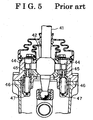
- Fig. 4 is a sectional view illustrating a conventional supporting apparatus of a shift lever.
- Fig. 5 is an enlarged sectional view, taken along line V-V in Fig. 4, in which a right-and-left direction corresponds to a select direction of a shift lever.
- pins 44, 44 protrude outwardly and in opposite directions from a large spherical ball 42 of a shift lever 41 and extend along the select direction of the shift lever 41.
- caps 45, 45 extending along an axial direction of the shift lever 41.
- the caps 45, 45 are positioned at right and left sides of the shift lever 41.
- Springs 46, 46 are respectively housed in the caps 45, 45.
- Pins 47, 47 are attached at bottom end surfaces of the springs 46, 46. Each spring 46 is compressively mounted between the corresponding cap 45 and the corresponding pin 47.
- a select return mechanism is provided at the left and right sides of the shift lever 41.
- the left portion of the select return mechanism is structured with the cap 45, the spring 46 and the pin 47, which are all arranged at the left side of the shift lever 41 in Fig. 5.
- the left portion of the select return mechanism is operated to return the shift lever 41 to a lower shift stage.
- the right portion of the select return mechanism is structured with the cap 45, the spring 46 and.the pin 47, which are all arranged at the right side of the shift lever 41 in Fig. 5.
- the right portion of the select return mechanism is operated to return the shift lever 41 to a higher shift stage.
- the select return mechanism of the supporting apparatus of a shift lever includes six components.
- JP09-21454A discloses therein a shift lever supporting apparatus for use in a manual transmission, in which a large spherical portion of a shift lever is supported by a shift lever retainer so that the large spherical portion of the shift lever rotates for shift and select operations.
- the large spherical portion of the shift lever includes a hollow shaped supporting portion on its rotational axis, by which the shift operation is achieved.
- Mounted in the hollow shaped supporting portion are a spring and spherical members (balls).
- the spherical members are biased by the force of the spring so as to impact with a cam of the shift lever retainer. In such circumstances, when the shift lever is operated for the select operation, the spherical members are respectively pushed to the inside of the supporting portion against the force of the spring and slide on inclined surfaces of the cams.
- the select return mechanism is provided at the left and right sides of the shift lever 41 and is structured with six components.
- JP09-21454A According to the shift lever supporting apparatus disclosed in JP09-21454A , the ball (a movable member) and the cam are each arranged at both the left and right sides of the shift lever, which structure specifies that components are arranged at both left and right sides of the shift lever in an identical manner as the structure illustrated in Figs. 4 and 5. JP09-21454A does not disclose therein a structure in which the ball is arranged only at one side of the shift lever.
- a select return mechanism of a shift lever includes: a spherical portion provided at the shift lever; a bolt extending along a select direction of the shift lever and threadably engaged with an inner surface of the spherical portion of the shift lever; a cover extending along the select direction of the shift lever and protruding outwardly from the inside of the spherical portion; a spring extending along the select direction of the shift lever and compressively mounted inside of the cover, one end of the spring being attached to an end surface of the bolt and elastically compressed in response to a select operation of the shift lever; a ball partially housed inside the cover and in contact with the other end of the spring so that the ball is biased by the spring; and a gradient adjusting member having at least one guiding surface on which the ball slides.
- the select return mechanism includes five components such as the bolt, the cove, the spring, the ball and the spacer (gradient adjusting member). As a result, it is possible to provide the select return mechanism which is structured with less components and which is manufactured at a reduced cost.
- the guiding surface on which the ball slides is divided to the lower-shift stage guiding surface and the higher-shift stage guiding surface. Therefore, it is possible, only by use of the single spring, to design and to achieve the select return loads of the lower and higher shift stage sides independently from each other. Further, by changing the gradient shape of each lower and higher shift stage guiding surface, select return load-spring deflection characteristics is achieved, which are different from conventional linear characteristics.
- the one end of the spring is in contact with the end surface of the bolt, which facilitates setting an initial length of the spring and further stabilizes an elastic compression of the spring during the select return movement of the shift lever. As a result, it is possible to obtain desired select return characteristics.
- the at least one guiding surface includes the first guiding surface, on which the ball 8 slides when the shift lever is manipulated to a lower-shift stage side along the select direction, and a second guiding surface, on which the ball slides when the shift lever is manipulated to a higher-shift stage side along the select direction.
- the first gradient of the first guiding surface is designed independently from the second gradient of the second guiding surface. In this case, it is possible to design and achieve the select return loads of the lower and higher shift stage sides independently from each other.
- the gradient of at least the corresponding guiding surface varies, and the at least one of the guiding surfaces and includes a curved surface.
- Fig. 1 is a sectional view illustrating a select return mechanism of a shift lever apparatus according to an embodiment of the present invention
- Fig. 2 is an enlarged view illustrating a relevant portion in Fig. 1;
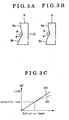
- Fig. 3 is a view for explaining a variation of the select return mechanism illustrated in Fig. 1, wherein, in Fig. 3A the gradient of a guiding surface is constant, and in Fig. 3B the gradient of the guiding surface is variant, and Fig. 3C is a load-deformation diagram;
- Fig. 4 is a sectional view illustrating a conventional shift lever supporting apparatus
- Fig. 5 is an enlarged view of Fig. 4 taken along line V-V.
- Fig. 1 is a sectional view illustrating a select return mechanism of a shift lever apparatus according to the embodiment of the present invention.
- the sectional view in Fig. 1 corresponds to a sectional view taken along line V-V in Fig. 4.
- a shift lever 1 which is manually operated at one end, is integrally provided with a large spherical portion 1a at an intermediate thereof and a small spherical portion 1b at the other end.
- the large spherical portion 1a is supported by a shift lever bush 2 so that the shift lever 1 is operated for shift and select operations.
- the small spherical portion 1b is connected to a shift and select shaft 3 that transmits the operation of the shift lever 1 to a transmission.
- a select return mechanism 4 of the embodiment incorporates therein: a bolt 5, which extends along the select direction (the left-and-right direction in Fig. 2) of the shift lever 1 and is threadably engaged with an inner surface of the large spherical portion 1a of the shift lever 1; a cover 6, which extends along the select direction of the shift lever 1 and protrudes from the inside of the spherical portion 1a to the outside thereof; and a spring 7, which extends along the select direction of the shift lever 1 and is compressively mounted inside of the cover 6.
- One end of the spring 7 is firmly attached to the end surface of the bolt 5 so that the spring 7 is compressed in response to the select operation of the shift lever 1.
- the select return mechanism 4 further incorporates therein, a ball 8, which is partially housed inside the cover 6 and is in contact with the other end of the spring 7 so that the ball 8 is biased by the spring 7 to the right direction in Fig. 2, and a spacer 9 (a gradient adjusting member), which is supported by a retainer 10 and is formed with guiding surfaces on which the ball 8 slides.
- the select return mechanism 4 includes five components such as the bolt 5, the cover 6, the spring 7, the ball 8 and the spacer 9.
- the guiding surfaces of the spacer 9 are: a lower-shift stage guiding surface 9a (serving as a first guiding surface) and a higher-shift stage guiding surface 9b (serving as a second guiding surface).
- a lower-shift stage guiding surface 9a serving as a first guiding surface
- a higher-shift stage guiding surface 9b serving as a second guiding surface.
- the lower-shift stage guiding surface 9a is formed at a gradient (angle of gradient, first gradient) ⁇ relative to the axis of the bolt 5, while the higher-shift stage guiding surface 9b is formed at a gradient (angle of gradient, second gradient) ⁇ relative to the axis of the bolt 5.
- the gradients ⁇ and ⁇ may be defined independently. According to the embodiment, as illustrated in Fig. 2, the gradient ⁇ of the lower-shift stage guiding surface 9a is not identical to the gradient ⁇ of the higher-shift stage guiding surface 9b ( ⁇ ⁇ ), because an amount of spring compression and a load applied to the spacer 9 upon the select operation to the higher-shift stage are greater than those generated upon the select operation to the lower-shift stage.
- the cover 6 may be press-fitted into the large spherical portion 1a of the shift lever 1 or may be press-fitted by the bolt 5.
- the guiding surfaces 9a and 9b are arranged in a manner where ends of the guiding surfaces 9a, 9b, which are located closer to the center of the spacer 9 in the axial direction of the shift lever 1, are located closer to the spacer 9 in the select direction than the other ends thereof, which are located away from the center of the spacer 9 in the axial direction of the shift lever 1.
- a groove which is a V-shape for example, is formed at a connecting point of the one ends of the guiding surfaces 9a, 9b.
- the cover 6 is inclined, and the ball 8 slides downward on the higher-shift stage guiding surface 9b while elastically compressing the spring 7.
- the elastic force which is accumulated in the compressed spring 7, acts as a force for returning the ball 8 to neutral, i.e., as a select return force for returning the shift lever 1 to neutral along the select direction.
- the select return force upon the select operation to the higher-shift stage (the left side in Fig. 2) is greater than that generated upon the select operation to the lower-shift stage (the right side in Fig. 1).
- the select load is large. That is, the load at the higher-shift stage side is greater than that at the lower-shift stage side.
- Fig. 3A the gradient ⁇ of the lower-shift stage side and the gradient ⁇ of the higher-shift stage side are each constant over each corresponding guiding surface.
- Fig. 3B the gradient ⁇ of the lower-shift stage side and the gradient ⁇ of the higher-shift stage side each vary over each corresponding guiding surface.
- Fig. 3C is a load-deformation diagram of the structures in Fig. 3A and in Fig. 3B. With reference to Figs.
- a load-deflection curve is a straight or linear line to whichever side the shift lever 1 is operated along the select direction.
- a linear loading characteristic select return force characteristic
- the gradient ⁇ of the lower-shift stage guiding surface 9a varies on the guiding surface 9a, i.e., where the guiding surface 9a is a curved surface
- the loading characteristic at the lower side is non-linear.
- the above description is applied to the gradient ⁇ of the higher-shift stage side being variable.
- the select return mechanism of the embodiment is applied to a shift lever supporting apparatus of a transmission for a vehicle, especially to a floor type shift lever supporting apparatus.
Landscapes
- Engineering & Computer Science (AREA)
- General Engineering & Computer Science (AREA)
- Mechanical Engineering (AREA)
- Arrangement Or Mounting Of Control Devices For Change-Speed Gearing (AREA)
- Control Of Transmission Device (AREA)
Applications Claiming Priority (1)
| Application Number | Priority Date | Filing Date | Title |
|---|---|---|---|
| JP2006225367A JP2008049737A (ja) | 2006-08-22 | 2006-08-22 | シフトレバーのセレクトリターン機構 |
Publications (2)
| Publication Number | Publication Date |
|---|---|
| EP1892437A2 true EP1892437A2 (de) | 2008-02-27 |
| EP1892437A3 EP1892437A3 (de) | 2008-04-16 |
Family
ID=38668914
Family Applications (1)
| Application Number | Title | Priority Date | Filing Date |
|---|---|---|---|
| EP07016044A Withdrawn EP1892437A3 (de) | 2006-08-22 | 2007-08-16 | Rückwärtsauswahlmechanismus |
Country Status (3)
| Country | Link |
|---|---|
| US (1) | US20080047384A1 (de) |
| EP (1) | EP1892437A3 (de) |
| JP (1) | JP2008049737A (de) |
Cited By (6)
| Publication number | Priority date | Publication date | Assignee | Title |
|---|---|---|---|---|
| CN102528416A (zh) * | 2011-12-13 | 2012-07-04 | 苏州工业园区高登威科技有限公司 | 一种用于为汽车档杆添加衬套的装置 |
| CN101439673B (zh) * | 2008-12-18 | 2012-10-03 | 奇瑞汽车股份有限公司 | 一种可自适应调节本体游隙的换档机构 |
| WO2016112967A1 (en) * | 2015-01-14 | 2016-07-21 | Kongsberg Automotive Ab | Gear shift lever assembly |
| CN106763716A (zh) * | 2017-02-14 | 2017-05-31 | 安徽新华学院 | 一种提高选档手感的直接操纵装置 |
| CN106812928A (zh) * | 2015-11-25 | 2017-06-09 | 长城汽车股份有限公司 | 一种排挡座 |
| EP3306143A1 (de) * | 2016-10-04 | 2018-04-11 | Fico Triad, S.A. | Schalthebelvorrichtung für motorfahrzeuge |
Families Citing this family (5)
| Publication number | Priority date | Publication date | Assignee | Title |
|---|---|---|---|---|
| CN102216870B (zh) * | 2008-11-21 | 2013-11-20 | 株式会社小松制作所 | 电气手柄装置 |
| US9021912B2 (en) | 2011-07-27 | 2015-05-05 | Kongsberg Automotive Ab | Shifting apparatus |
| US20150198238A1 (en) * | 2014-01-13 | 2015-07-16 | Legend Gear & Transmission, Inc. | Shifter assembly |
| CN105936213B (zh) * | 2016-06-30 | 2018-03-23 | 贵州华阳电工有限公司 | 自动回中机构 |
| CN107195491A (zh) * | 2017-06-08 | 2017-09-22 | 陕西法士特齿轮有限责任公司 | 一种压力开关 |
Family Cites Families (10)
| Publication number | Priority date | Publication date | Assignee | Title |
|---|---|---|---|---|
| GB1327040A (en) * | 1969-12-10 | 1973-08-15 | Cav Ltd | Gear change switch |
| US3957241A (en) * | 1974-12-16 | 1976-05-18 | Acorn Engineering Company, Inc. | Ball joint relievable hanger for towels and the like |
| JPS51108162A (en) * | 1975-03-19 | 1976-09-25 | Mitsubishi Motors Corp | Kontoroorurebaano boshinsochi |
| JPS5725284Y2 (de) * | 1978-08-31 | 1982-06-01 | ||
| JPS5717830U (de) * | 1980-07-04 | 1982-01-29 | ||
| US5345050A (en) * | 1993-06-01 | 1994-09-06 | Caterpillar Inc. | Switch actuating assembly |
| JP3392239B2 (ja) * | 1994-10-21 | 2003-03-31 | 株式会社タイトー | 模擬シフトレバー機構 |
| JP3650784B2 (ja) * | 1995-07-05 | 2005-05-25 | 津田工業株式会社 | 手動式変速機用シフトレバーの支持装置 |
| US6321616B1 (en) * | 1998-11-27 | 2001-11-27 | United Parts Fhs Automobil Systeme Gmbh | Gear catching for a shift transmission |
| EP1239192B1 (de) * | 2001-03-02 | 2010-12-29 | Toyota Jidosha Kabushiki Kaisha | Schaltvorrichtung für ein Kraftfahrzeug |
-
2006
- 2006-08-22 JP JP2006225367A patent/JP2008049737A/ja active Pending
-
2007
- 2007-08-16 US US11/840,078 patent/US20080047384A1/en not_active Abandoned
- 2007-08-16 EP EP07016044A patent/EP1892437A3/de not_active Withdrawn
Cited By (6)
| Publication number | Priority date | Publication date | Assignee | Title |
|---|---|---|---|---|
| CN101439673B (zh) * | 2008-12-18 | 2012-10-03 | 奇瑞汽车股份有限公司 | 一种可自适应调节本体游隙的换档机构 |
| CN102528416A (zh) * | 2011-12-13 | 2012-07-04 | 苏州工业园区高登威科技有限公司 | 一种用于为汽车档杆添加衬套的装置 |
| WO2016112967A1 (en) * | 2015-01-14 | 2016-07-21 | Kongsberg Automotive Ab | Gear shift lever assembly |
| CN106812928A (zh) * | 2015-11-25 | 2017-06-09 | 长城汽车股份有限公司 | 一种排挡座 |
| EP3306143A1 (de) * | 2016-10-04 | 2018-04-11 | Fico Triad, S.A. | Schalthebelvorrichtung für motorfahrzeuge |
| CN106763716A (zh) * | 2017-02-14 | 2017-05-31 | 安徽新华学院 | 一种提高选档手感的直接操纵装置 |
Also Published As
| Publication number | Publication date |
|---|---|
| US20080047384A1 (en) | 2008-02-28 |
| JP2008049737A (ja) | 2008-03-06 |
| EP1892437A3 (de) | 2008-04-16 |
Similar Documents
| Publication | Publication Date | Title |
|---|---|---|
| EP1892437A2 (de) | Rückwärtsauswahlmechanismus | |
| JP3650784B2 (ja) | 手動式変速機用シフトレバーの支持装置 | |
| EP1923607B1 (de) | Gangschaltungsvorrichtung | |
| EP1958817B1 (de) | Sitzabfederungs-Lagersystem | |
| EP1992806A1 (de) | Verbrennungsmotor mit variablem Verdichtungsmechanimus | |
| AU2003268823A1 (en) | A Shift Control Apparatus for a Transmission | |
| US4519268A (en) | Gear shift apparatus for manual transmission | |
| US6167777B1 (en) | Tiltable steering column lock mechanism | |
| DE4037786C2 (de) | ||
| DE102015214658A1 (de) | Fahrpedalmodul für ein Kraftfahrzeug | |
| CN112026977A (zh) | 自动自行车踏板 | |
| US11287029B2 (en) | Damping mechanism for a shift selector assembly and a shift selector assembly comprising the damping mechanism | |
| JP2019038292A (ja) | 空調用レジスタ | |
| US20050160861A1 (en) | Gear shift assembly | |
| US8127637B2 (en) | Gear change arrangement and a gearbox | |
| DE102004024089B3 (de) | Lagervorrichtung für eine Federanordnung | |
| DE102007018731B4 (de) | Schalt- und Wählvorrichtung | |
| DE102013006178B3 (de) | Tastschalteranordnung | |
| WO2000005636A1 (de) | Arretierelement zur sicherung von verstellpositionen | |
| DE202014102504U1 (de) | Schwenkbedienelement mit multifunktionaler Blattfeder | |
| US20090178505A1 (en) | Adjustable shift lever assembly for a transmission | |
| DE102006052832B4 (de) | Mäanderfeder zur Anordnung zwischen zwei Elementen | |
| CN110325392B (zh) | 换挡装置 | |
| EP1564450B1 (de) | Schaltarretierung | |
| US20050028631A1 (en) | Compact short-throw shifter linkage |
Legal Events
| Date | Code | Title | Description |
|---|---|---|---|
| PUAI | Public reference made under article 153(3) epc to a published international application that has entered the european phase |
Free format text: ORIGINAL CODE: 0009012 |
|
| AK | Designated contracting states |
Kind code of ref document: A2 Designated state(s): AT BE BG CH CY CZ DE DK EE ES FI FR GB GR HU IE IS IT LI LT LU LV MC MT NL PL PT RO SE SI SK TR |
|
| AX | Request for extension of the european patent |
Extension state: AL BA HR MK YU |
|
| PUAL | Search report despatched |
Free format text: ORIGINAL CODE: 0009013 |
|
| AK | Designated contracting states |
Kind code of ref document: A3 Designated state(s): AT BE BG CH CY CZ DE DK EE ES FI FR GB GR HU IE IS IT LI LT LU LV MC MT NL PL PT RO SE SI SK TR |
|
| AX | Request for extension of the european patent |
Extension state: AL BA HR MK RS |
|
| RIC1 | Information provided on ipc code assigned before grant |
Ipc: F16H 59/04 20060101ALI20080311BHEP Ipc: F16H 59/02 20060101AFI20071120BHEP |
|
| AKX | Designation fees paid | ||
| REG | Reference to a national code |
Ref country code: DE Ref legal event code: 8566 |
|
| STAA | Information on the status of an ep patent application or granted ep patent |
Free format text: STATUS: THE APPLICATION IS DEEMED TO BE WITHDRAWN |
|
| 18D | Application deemed to be withdrawn |
Effective date: 20081017 |