EP1892199B1 - System mit einer Brühmaschine und einer Portionskapsel - Google Patents
System mit einer Brühmaschine und einer Portionskapsel Download PDFInfo
- Publication number
- EP1892199B1 EP1892199B1 EP07013691A EP07013691A EP1892199B1 EP 1892199 B1 EP1892199 B1 EP 1892199B1 EP 07013691 A EP07013691 A EP 07013691A EP 07013691 A EP07013691 A EP 07013691A EP 1892199 B1 EP1892199 B1 EP 1892199B1
- Authority
- EP
- European Patent Office
- Prior art keywords
- pod
- portioned
- base
- soft disc
- disc
- Prior art date
- Legal status (The legal status is an assumption and is not a legal conclusion. Google has not performed a legal analysis and makes no representation as to the accuracy of the status listed.)
- Not-in-force
Links
- 239000002775 capsule Substances 0.000 title description 135
- 239000000463 material Substances 0.000 claims abstract description 16
- 229920001296 polysiloxane Polymers 0.000 claims description 26
- 235000013361 beverage Nutrition 0.000 claims description 25
- 239000000126 substance Substances 0.000 claims description 21
- 239000007788 liquid Substances 0.000 claims description 18
- XLYOFNOQVPJJNP-UHFFFAOYSA-N water Substances O XLYOFNOQVPJJNP-UHFFFAOYSA-N 0.000 claims description 18
- 244000299461 Theobroma cacao Species 0.000 claims description 13
- 235000009470 Theobroma cacao Nutrition 0.000 claims description 10
- 235000013336 milk Nutrition 0.000 claims description 7
- 239000008267 milk Substances 0.000 claims description 7
- 210000004080 milk Anatomy 0.000 claims description 7
- 239000000843 powder Substances 0.000 claims description 7
- 239000007787 solid Substances 0.000 claims description 7
- 235000014666 liquid concentrate Nutrition 0.000 claims description 5
- 235000008504 concentrate Nutrition 0.000 claims description 4
- 239000012141 concentrate Substances 0.000 claims description 4
- 229920001971 elastomer Polymers 0.000 claims description 4
- 239000005060 rubber Substances 0.000 claims description 4
- 235000019219 chocolate Nutrition 0.000 claims description 3
- 235000012171 hot beverage Nutrition 0.000 claims description 3
- 235000014109 instant soup Nutrition 0.000 claims description 3
- 229920002379 silicone rubber Polymers 0.000 claims description 3
- 229920003051 synthetic elastomer Polymers 0.000 claims description 3
- 239000005061 synthetic rubber Substances 0.000 claims description 3
- 244000043261 Hevea brasiliensis Species 0.000 claims 2
- 229920003052 natural elastomer Polymers 0.000 claims 2
- 229920001194 natural rubber Polymers 0.000 claims 2
- 235000008476 powdered milk Nutrition 0.000 claims 2
- XUIMIQQOPSSXEZ-UHFFFAOYSA-N Silicon Chemical compound [Si] XUIMIQQOPSSXEZ-UHFFFAOYSA-N 0.000 abstract 2
- 229910052710 silicon Inorganic materials 0.000 abstract 2
- 239000010703 silicon Substances 0.000 abstract 2
- 230000037431 insertion Effects 0.000 abstract 1
- 238000003780 insertion Methods 0.000 abstract 1
- 210000004872 soft tissue Anatomy 0.000 description 12
- 239000000853 adhesive Substances 0.000 description 11
- 230000001070 adhesive effect Effects 0.000 description 11
- 238000013124 brewing process Methods 0.000 description 8
- 235000013353 coffee beverage Nutrition 0.000 description 8
- NIXOWILDQLNWCW-UHFFFAOYSA-M Acrylate Chemical compound [O-]C(=O)C=C NIXOWILDQLNWCW-UHFFFAOYSA-M 0.000 description 3
- 238000000034 method Methods 0.000 description 3
- -1 polyethylene Polymers 0.000 description 3
- 239000004743 Polypropylene Substances 0.000 description 2
- XAGFODPZIPBFFR-UHFFFAOYSA-N aluminium Chemical compound [Al] XAGFODPZIPBFFR-UHFFFAOYSA-N 0.000 description 2
- 229910052782 aluminium Inorganic materials 0.000 description 2
- 239000000203 mixture Substances 0.000 description 2
- 239000004033 plastic Substances 0.000 description 2
- 229920003023 plastic Polymers 0.000 description 2
- 229920000728 polyester Polymers 0.000 description 2
- 229920001155 polypropylene Polymers 0.000 description 2
- 230000000717 retained effect Effects 0.000 description 2
- 239000007779 soft material Substances 0.000 description 2
- 239000004698 Polyethylene Substances 0.000 description 1
- 239000004793 Polystyrene Substances 0.000 description 1
- 235000008453 RTD coffee Nutrition 0.000 description 1
- 239000012790 adhesive layer Substances 0.000 description 1
- 230000001419 dependent effect Effects 0.000 description 1
- 238000007865 diluting Methods 0.000 description 1
- 238000000605 extraction Methods 0.000 description 1
- 239000004744 fabric Substances 0.000 description 1
- 239000006260 foam Substances 0.000 description 1
- 239000011888 foil Substances 0.000 description 1
- 235000013305 food Nutrition 0.000 description 1
- 239000003292 glue Substances 0.000 description 1
- 239000011185 multilayer composite material Substances 0.000 description 1
- 230000002093 peripheral effect Effects 0.000 description 1
- 239000002985 plastic film Substances 0.000 description 1
- 229920006255 plastic film Polymers 0.000 description 1
- 229920000573 polyethylene Polymers 0.000 description 1
- 229920002223 polystyrene Polymers 0.000 description 1
- 238000007789 sealing Methods 0.000 description 1
- 239000004945 silicone rubber Substances 0.000 description 1
- 239000002689 soil Substances 0.000 description 1
- 238000009423 ventilation Methods 0.000 description 1
Images

Classifications
-
- B—PERFORMING OPERATIONS; TRANSPORTING
- B65—CONVEYING; PACKING; STORING; HANDLING THIN OR FILAMENTARY MATERIAL
- B65D—CONTAINERS FOR STORAGE OR TRANSPORT OF ARTICLES OR MATERIALS, e.g. BAGS, BARRELS, BOTTLES, BOXES, CANS, CARTONS, CRATES, DRUMS, JARS, TANKS, HOPPERS, FORWARDING CONTAINERS; ACCESSORIES, CLOSURES, OR FITTINGS THEREFOR; PACKAGING ELEMENTS; PACKAGES
- B65D85/00—Containers, packaging elements or packages, specially adapted for particular articles or materials
- B65D85/70—Containers, packaging elements or packages, specially adapted for particular articles or materials for materials not otherwise provided for
- B65D85/804—Disposable containers or packages with contents which are mixed, infused or dissolved in situ, i.e. without having been previously removed from the package
- B65D85/8043—Packages adapted to allow liquid to pass through the contents
-
- A—HUMAN NECESSITIES
- A47—FURNITURE; DOMESTIC ARTICLES OR APPLIANCES; COFFEE MILLS; SPICE MILLS; SUCTION CLEANERS IN GENERAL
- A47J—KITCHEN EQUIPMENT; COFFEE MILLS; SPICE MILLS; APPARATUS FOR MAKING BEVERAGES
- A47J31/00—Apparatus for making beverages
- A47J31/40—Beverage-making apparatus with dispensing means for adding a measured quantity of ingredients, e.g. coffee, water, sugar, cocoa, milk, tea
- A47J31/407—Beverage-making apparatus with dispensing means for adding a measured quantity of ingredients, e.g. coffee, water, sugar, cocoa, milk, tea with ingredient-containing cartridges; Cartridge-perforating means
Definitions
- the invention relates to a system with a brewing machine and a portion capsule and an associated portion capsule.
- a system is known with a brewing machine and a portion capsule.
- the brewing machine is adapted for making a hot beverage, in particular a coffee beverage, by means of a Portiönskapsel with a capsule lid and a capsule bottom and has a pressurized water device (with a water reservoir, a feed pump, a boiler and a brewing chamber), a Portionskapselhalter (which also includes parts of the brewing chamber contains) and a control on.
- the portion capsule holder are associated with two relatively movable piercing means (upper mandrel and lower mandrel), with the aid of hot water through the capsule lid into the interior of the portion capsule and the finished Drink can pass through the capsule bottom from the portion capsule.
- a portion capsule which is closed on all sides in the delivery state and contains a beverage substance, in particular ground coffee, is inserted into the portion capsule holder or the brewing chamber.
- the upper mandrel pierces the capsule lid.
- the lower mandrel penetrates the capsule bottom either when closing the brewing chamber or else during the brewing process.
- the pump delivers hot water into the portion capsule, which leaves the portion capsule after extraction of the ground coffee as a ready-to-drink coffee beverage through the lower mandrel (which is configured as a hollow mandrel in the previously known brewing machine).
- the brewing chamber is opened again so that the portion capsule can be removed by the user.
- the residual liquid contained in the portion capsule is largely bound by the extracted ground coffee (moist coffee grounds) so that the portion capsule can be removed without liquid dripping from the capsule bottom.
- portion capsules are used which are filled, for example, with cocoa powder or milk powder or with liquid concentrate of cocoa or milk.
- a portion capsule inserted into the brewing chamber the brewing chamber is closed and the brewing process is carried out, the portion capsule on the capsule lid and the capsule bottom is pierced.
- the pump conveys hot water into the portion capsule to make the beverage, thereby dissolving or diluting the concentrate contained therein and ready for use Drink leaving the brewing chamber on the hollow mandrel at the bottom. To stop the process, the pump is switched off.
- the portion capsule is prevented from flowing out, because neither from the hydraulic system (which has the water tank, the pump, the boiler and a valve) nor from the environment can air flow into the portion capsule.
- the portion capsule is aerated, and the possibly still hot water can flow out of the portion capsule while the environment pollute or even endanger the user.
- the WO 00/56629 A shows a portion capsule, which has a device in the bottom area, which is to retain after opening the capsule solids in the capsule.
- This device may consist of a fabric or a foam or be designed as a valve device.
- the system according to the invention comprises a brewing machine and a portion capsule.
- the brewing machine is adapted for making a hot beverage by means of a portion capsule with a capsule lid and a capsule bottom and has a pressurized water device, a portion capsule holder and a controller.
- the portion capsule holders are associated with two relatively movable piercing means, which are adapted to pierce the capsule lid and the capsule bottom during or after inserting the portion capsule into the portion capsule holder so that hot water flows through the capsule lid into the interior of the portion capsule and beverage through the capsule bottom can get out of the portion capsule.
- Such a brewing machine is eg in the DE 10 2004 056 224 A1 disclosed in detail, as explained above.
- the portion capsule of the system according to the invention is closed on all sides in the delivery state and contains a beverage substance.
- the capsule bottom is adapted to close when pulling out of the capsule bottom associated piercing from the capsule bottom again.
- the capsule bottom comprises a plastic disc, namely of silicone (preferably a peroxide-free solid silicone), silicone rubber, rubber, rubber or synthetic rubber.
- the lower mandrel pierces the capsule bottom and thereby the soft tissue disc.
- the brewing chamber is opened to remove the spent portion capsule.
- the upper mandrel and the lower mandrel withdraw from the portion capsule.
- no liquid escapes from the portion capsule since the capsule bottom automatically reseals due to the material properties of the soft tissue disc. Because the material of the plastic disc goes into his Starting position back and closes the created by the lower mandrel hole in the capsule bottom.
- the hole is already sealed before the lower mandrel is completely pulled out of the soft tissue disc.
- the portion capsule Therefore, it can be safely removed and disposed of without polluting the environment.
- the capsule bottom can be formed by the soft tissue disc.
- the capsule bottom has a foil to which the soft tissue disc is attached.
- a bottom structure and a side wall of the portion capsule are integrally formed with each other, preferably as a molded part or as a deep-drawn part, wherein the soft material disc is attached to the floor structure.
- the soft tissue disc may be glued, or welded or held by a support structure.
- the latter option is particularly advantageous when adhesive bonds are problematic because of the nature of the materials used.
- support structures are a carrier disc, preferably with a central opening which holds the soft tissue disc on the capsule bottom, and a support structure with two carrier discs, preferably each with a central opening, between which the soft tissue disc is arranged. If the soft material disc is clamped between two such carrier discs, an additional seal between the carrier discs and the soft tissue disc is unnecessary because of the material properties of the soft tissue disc.
- the support structure is glued in preferred embodiments with a portion of the portion capsule and / or welded and / or screwed.
- adhesives are used which are compatible with the materials used to connect the parts of the support structure and the portion capsule and are preferably also food grade, such as acrylate adhesive.
- the support structure is latched to a portion of the portion capsule. This has the advantage that adhesive bonds completely unnecessary.
- the soft tissue disc preferably has a thickness in the range of 0.2 mm to 1.5 mm, preferably 0.5 mm.
- the portion capsule of the system according to the invention may also be mixed with conventional beverage substances, e.g. Coffee powder can be used.
- beverage substances e.g. Coffee powder can be used.
- the advantages of the invention come into play when the beverage substance has a liquid and / or when solid portions of the beverage substance in water are at least largely soluble or dispersible, so if the beverage substance itself is not able to retain residual liquid in a spent portion capsule ,
- Preferred beverage substances are cocoa powder, chocolate, cocoa liquid concentrate, milk powder, milk-liquid concentrate, instant soup or mixtures thereof.
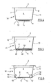
- FIGS. 1 to 3 Fig. 1 schematically illustrates the operation of a portion capsule 1 in a system with a brewing machine and a portion capsule during the brewing process.
- the portion capsule 1 has a capsule lid 2 and a capsule bottom 4 and is closed on all sides before use.
- a beverage substance 6 Inside the portion capsule 1 is a beverage substance 6, which is shown in the embodiment as a liquid concentrate (eg with cocoa or milk) with a level 7.
- the capsule bottom 4 in the exemplary embodiment has a closed bottom structure 8, which is formed integrally with a side wall 10 and an outwardly projecting flange 12 in the upper region of the portion capsule 1, e.g. as a deep-drawn part or molded part.
- the capsule lid 2 is connected to the flange 12, e.g. by sealing.
- portion capsule 1 corresponds to that of a conventional portion capsule.
- portion capsules materials in question for example aluminum or a plastic film for the capsule lid 2 and for example aluminum, polyester, polystyrene, polyethylene, polypropylene or multilayer composite materials for the bottom structure 8, the side wall 10 and the flange 12th
- a silicone disk 14 is applied to the bottom structure 8 from the outside in the capsule bottom 4 and connected to the bottom structure 8, as described with reference to FIG FIG. 4 explained in more detail.
- FIG. 1 is shown in a schematic manner, as the portion capsule 1 is inserted into a brewing machine.
- the brewing machine is designed, for example, as in the DE 10 2004 056 224 A1 described, and has a portion cap holder not shown here in the figures, which is a separate part in the embodiment.
- the portion capsule holder is inserted and locked in the brewing machine. In the locking process, the portion capsule holder lifts with the portion capsule 1, so that serving as a piercing upper mandrel 16 perforates the capsule cover 2.
- FIG. 2 the last state described is shown. It can also be seen how, during the brewing process, hot water 20 reaches the interior of the portion capsule 1 through the upper mandrel 16 shown as a hollow mandrel in the exemplary embodiment and dilutes the liquid beverage substance 6.
- the upper mandrel 16 is not a hollow mandrel, but hot water passes through the created in the upper mandrel 16 opening in the capsule lid 2 inside the portion capsule 1.
- the capsule cover 2 is during this process by a circumferential seal the brewing chamber at his Top pressure-tight sealed against the environment.
- the spent portion capsule 1 should be removed.
- the portion capsule holder is unlocked, and the upper mandrel 16 and the lower mandrel 18 move away from each other. This condition is in FIG. 3 shown.
- the interior of the portion capsule 1 is ventilated by the created by the upper mandrel 16 opening 24.
- the residual liquid 29 contained in the portion capsule 1 can not leak through the opening 26 formed in the bottom structure 8 by the lower mandrel 18, but is retained by the silicone disk 14.
- the opening in the silicone disk 14 closes automatically, so that a point-like closure point 28 is formed, through which the residual liquid 29 can not pass.
- the portion capsule 1 can therefore be conveniently removed without liquid leaking.
- the portion capsule 1 is in FIG. 4 more specifically, and designated 30 herein. The remaining reference numerals are retained.
- the silicone disk 14 is attached to the bottom structure 8 of the capsule bottom 4 with a suitable adhesive material (eg an acrylate adhesive).
- the adhesive layer is designated 32.
- the silicone disk 14 is in this example 0.5 mm thick and consists of peroxide-free silicone.
- a floor structure 8 and a silicone disk 14 may not be able to bond together in a suitable manner.
- food-safe adhesives are not available for all material combinations.
- the silicone disc is not glued directly to the floor structure.
- the FIG. 5 shows a portion capsule 40, which has the same basic structure as the portion capsule according to FIG. 4 , which is why the same reference numerals are used for corresponding parts.
- the silicone disk 14 is clamped between a first carrier disk 42, which has a central opening 44, and a second carrier disk 46 with a central opening 48.
- the first carrier disk 42 and the second carrier disk 46 each have an annular groove in which the silicone disk 14 lies.
- the two carrier discs 42 and 46 which are made of polyester or polypropylene, for example, are glued together with each other in their peripheral edge zones.
- the carrier disk 42 is attached to the bottom structure 8 at the edge with a suitable adhesive material (eg an acrylate adhesive).
- a suitable adhesive material eg an acrylate adhesive
- the carrier discs 42 and 46 are each provided with an opening 44 and 48, they do not interfere when the lower mandrel 18 penetrates into the portion capsule 40. Any leaks of the bonds are of no importance, since they can not form access to the capsule interior before the perforation of the capsule bottom 4 and since only small amounts of liquid could leak after the perforation by these leaks.
- the silicone disk consists of peroxide-free silicone and has a thickness in the range from 0.2 to 1.5 mm, preferably 0.5 mm.
- the bottom structure 8 of the capsule bottom 4 is according to FIG. 6 provided with a recess 51, in which the silicone plate 14 is inserted from the outside.
- the silicone disk 14 is held by a ring-like fastening part 52, which has an opening 54 in its central area and an inwardly curved edge 56 on its periphery.
- the edge 56 is locked in a circumferential annular groove 58, which is provided in the lower region of the side wall 10 of the portion capsule 50. Because of the elastic properties of the silicone disk 14, the silicone disk 14 lies close to the floor structure 8. Therefore, in the perforated state, comparable to the illustration in FIG. 3 , no residual liquid from the portion capsule 50 leak.
- a fastening part for the silicone disc 14 is not locked to the body of the portion capsule, but thermally welded, glued or screwed.
- the portion capsules 1, 30, 40 and 50 have a circular cross-section in the embodiments.
Landscapes
- Engineering & Computer Science (AREA)
- Mechanical Engineering (AREA)
- Apparatus For Making Beverages (AREA)
- Soy Sauces And Products Related Thereto (AREA)
Description
- Die Erfindung betrifft ein System mit einer Brühmaschine und einer Portionskapsel sowie eine zugehörige Portionskapsel.
- Aus der
DE 10 2004 056 224 A1 ist ein System mit einer Brühmaschine .und einer Portionskapsel bekannt. Die Brühmaschine ist zum Fertigen eines heißen Getränks, insbesondere eines Kaffeegetränks, mittels einer Portiönskapsel mit einem Kapseldeckel und einem Kapselboden eingerichtet und weist eine Druckwassereinrichtung (mit einem Wasservorratsbehälter, einer Förderpumpe, einem Boiler und einer Brühkammer), einen Portionskapselhalter (der auch Teile der Brühkammer enthält) und eine Steuerung auf. Dem Portionskapselhalter sind zwei relativ zueinander bewegbare Aufstechmittel (oberer Dorn und unterer Dorn) zugeordnet, mit deren Hilfe heißes Wasser durch den Kapseldeckel in den Innenraum der Portionskapsel und das fertige Getränk durch den Kapselboden aus der Portionskapsel gelangen kann. - Bei Benutzung der vorbekannten Brühmaschine wird zunächst eine Portionskapsel, die im Lieferzustand allseitig geschlossen ist und eine Getränkesubstanz, insbesondere Mahlkaffee, enthält, in den Portionskapselhalter bzw. die Brühkammer eingelegt. Beim Schließen der Brühkammer durchsticht der obere Dorn den Kapseldeckel. Je nach Druckaufbau in der Portionskapsel durchstößt der untere Dorn den Kapselboden entweder bereits beim Schließen der Brühkammer oder sonst während des Brühvorgangs. Die Pumpe fördert heißes Wasser in die Portionskapsel, das die Portionskapsel nach der Extraktion des Kaffeemehls als gebrauchsfertiges Kaffeegetränk durch den unteren Dorn (der bei der vorbekannten Brühmaschine als Hohldorn ausgestaltet ist) wieder verlässt. Nach Beendigung des Brühvorgangs wird die Brühkammer wieder geöffnet, so dass die Portionskapsel vom Benutzer entnommen werden kann. Dabei ist die in der Portionskapsel enthaltene Restflüssigkeit von dem extrahierten Kaffeemehl weitgehend gebunden (feuchter Kaffeesatz), so dass man die Portionskapsel entnehmen kann, ohne dass dabei Flüssigkeit aus dem Kapselboden tropft.
- Im Prinzip ist die vorbekannte Brühmaschine auch zum Zubereiten anderer Getränke als Kaffee geeignet, z.B. von heißem Kakao oder heißer Milch. In diesem Fall werden Portionskapseln benutzt, die z.B. mit Kakaopulver oder Milchpulver oder mit Flüssigkonzentrat von Kakao oder Milch gefüllt sind. Wenn nun, wie zuvor anhand der Verwendung von Portionskapseln mit Kaffee erläutert, eine Portionskapsel in die Brühkammer eingelegt, die Brühkammer geschlossen und der Brühvorgang durchgeführt wird, wird die Portionskapsel am Kapseldeckel und am Kapselboden angestochen. Die Pumpe fördert zur Herstellung des Getränks heißes Wasser in die Portionskapsel, wodurch das darin enthaltene Konzentrat gelöst oder verdünnt wird und als gebrauchsfertiges Getränk die Brühkammer über den Hohldorn an der Unterseite verlässt. Zur Beendigung des Vorgangs wird die Pumpe abgeschaltet. Das restliche heiße Wasser verbleibt auch nach dem Abschalten der Pumpe in der Portionskapsel, solange die Brühkammer luftdicht verschlossen ist. Bei der vorbekannten Brühmaschine wird nämlich ein Ausfließen der Portionskapsel dadurch verhindert, dass weder aus dem hydraulischen System (das den Wassertank, die Pumpe, den Boiler und ein Ventil aufweist), noch aus der Umgebung Luft in die Portionskapsel nachströmen kann. Sobald jedoch die Brühkammer geöffnet wird, um die verbrauchte Portionskapsel zu entnehmen, strömt durch den sich öffnenden Spalt zwischen der Brühkammer und ihrem Deckel Luft nach, die Portionskapsel wird dabei belüftet, und das gegebenenfalls noch heiße Wasser kann aus der Portionskapsel ausfließen und dabei die Umgebung verschmutzen oder gar den Benutzer gefährden.
- Die
WO 00/56629 A - Es ist Aufgabe der Erfindung, ein System mit der vorbekannten Brühmaschine und einer Portionskapsel neuen Nutzungsmöglichkeiten zuzuführen, insbesondere wenn die Pörtionskapsel keine wasserbindende Getränkesubstanz enthält, und die aus
WO 00/56629 A - Diese Aufgabe wird gelöst durch ein System mit einer Brühmaschine und einer Portionskapsel mit den Merkmalen des Anspruchs 1. Der Anspruch 14 ist direkt auf die Portionskapsel gerichtet. Vorteilhafte Ausgestaltungen der Erfindung ergeben sich aus den Unteransprüchen.
- Das erfindungsgemäße System weist eine: Brühmaschine und eine Portionskapsel auf. Die Brühmaschine ist zum Fertigen eines heißen Getränks mittels einer Portionskapsel mit einem Kapseldeckel und einem Kapselboden eingerichtet und weist eine Druckwassereinrichtung, einen Portionskapselhalter und eine Steuerung auf. Dem Portionskapselhalter sind zwei relativ zueinander bewegbare Aufstechmittel zugeordnet, die dazu eingerichtet sind, beim oder nach dem Einsetzen der Portionskapsel in den Portionskapselhalter den Kapseldeckel sowie den Kapselboden zu durchstoßen, so dass heißes Wasser durch den Kapseldeckel in den Innenraum der Portionskapsel und Getränk durch den Kapselboden aus der Portionskapsel gelangen kann. Eine derartige Brühmaschine ist z.B. in der
DE 10 2004 056 224 A1 im Einzelnen offenbart, wie oben erläutert. - Die Portionskapsel des erfindungsgemäßen Systems ist im Lieferzustand allseitig geschlossen und enthält eine Getränkesubstanz. Der Kapselboden ist dazu eingerichtet, sich beim Herausziehen des dem Kapselboden zugeordneten Aufstechmittels aus dem Kapselboden wieder zu schließen. Zu diesem Zweck weist der Kapselboden eine Weichstoffscheibe auf, und zwar aus Silikon (vorzugsweise einem peroxidfreien Vollsilikon), Silikonkautschuk, Gummi, Kautschuk oder synthetischem Kautschuk.
- Wenn die Portionskapsel des erfindungsgemäßen Systems in der zuvor erläuterten Weise benutzt wird, durchstößt der untere Dorn den Kapselboden und dabei die Weichstoffscheibe. Nachdem der Brühvorgang beendet ist, wird die Brühkammer geöffnet, um die verbrauchte Portionskapsel zu entnehmen. Dabei ziehen sich der obere Dorn und der untere Dorn aus der Portionskapsel zurück. Trotz der Belüftung durch das von dem oberen Dorn im Kapseldeckel gebildete Loch tritt keine Flüssigkeit aus der Portionskapsel aus, da sich der Kapselboden wegen der Materialeigenschaften der Weichstoffscheibe selbsttätig wieder abdichtet. Denn das Material der Weichstoffscheibe geht in seine Ausgangsstellung zurück und verschließt dabei das von dem unteren Dorn geschaffene Loch im Kapselboden. Je nach den Eigenschaften der Weichstoffscheibe, insbesondere dem Rückstellverhalten des Materials, ist das Loch bereits abgedichtet, bevor der untere Dorn vollständig aus der Weichstoffscheibe herausgezogen ist. Die Portionskapsel kann daher gefahrlos entnommen und entsorgt werden, ohne dass dabei die Umgebung verschmutzt wird.
- Es gibt verschiedene Möglichkeiten, die Weichstoffscheibe an der Portionskapsel anzubringen. So kann der Kapselboden durch die Weichstoffscheibe gebildet sein. Oder der Kapselboden weist eine Folie auf, an der die Weichstoffscheibe befestigt ist. Bei einer bevorzugten Ausführungsform sind eine Bodenstruktur und eine Seitenwandung der Portionskapsel einstückig miteinander ausgebildet, vorzugsweise als Spritzteil oder als Tiefziehteil, wobei die Weichstoffscheibe an der Bodenstruktur befestigt ist.
- Die Weichstoffscheibe kann angeklebt, oder angeschweißt oder auch von einer Haltestruktur gehalten sein. Die letztere Möglichkeit ist besonders vorteilhaft, wenn Klebeverbindungen wegen der Art der verwendeten Materialien problematisch sind.
- Beispiele für Haltestrukturen sind eine Trägerscheibe, vorzugsweise mit einer zentralen Öffnung, die die Weichstoffscheibe am Kapselboden hält, sowie eine Haltestruktur mit zwei Trägerscheiben, vorzugsweise jeweils mit einer zentralen Öffnung, zwischen denen die Weichstoffscheibe angeordnet ist. Wenn die Weichstoffscheibe zwischen zwei solchen Trägerscheiben eingeklemmt ist, erübrigt sich wegen der Materialeigenschaften der Weichstoffscheibe eine zusätzliche Abdichtung zwischen den Trägerscheiben und der Weichstoffscheibe.
- Die Haltestruktur ist bei bevorzugten Ausführungsformen mit einem Bereich der Portionskapsel verklebt und/oder verschweißt und/oder verschraubt. Dabei werden Klebstoffe benutzt, die mit den verwendeten Materialien der zu verbindenden Teile der Haltestruktur und der Portionskapsel verträglich sind und vorzugsweise auch lebensmitteltauglich sind, z.B. Acrylatkleber.
- Bei anderen Ausführungsformen ist die Haltestruktur mit einem Bereich der Portionskapsel verrastet. Dies hat den Vorteil, dass sich Klebeverbindungen ganz erübrigen.
- Die Weichstoffscheibe hat vorzugsweise eine Dicke im Bereich von 0,2 mm bis 1,5 mm, vorzugsweise 0,5 mm.
- Im Prinzip kann die Portionskapsel des erfindungsgemäßen Systems auch mit herkömmlichen Getränkesubstanzen wie z.B. Kaffeepulver verwendet werden. Die Vorteile der Erfindung kommen dann zum Tragen, wenn die Getränkesubstanz eine Flüssigkeit aufweist und/oder wenn feste Anteile der Getränkesubstanz in Wasser zumindest weitgehend lösbar bzw. dispergierbar sind, wenn also die Getränkesubstanz selbst nicht in der Lage ist, Restflüssigkeit in einer verbrauchten Portionskapsel zurückzuhalten. Bevorzugte Getränkesubstanzen sind Kakaopulver, Schokolade, Kakao-Flüssigkonzentrat, Milchpulver, Milch-Flüssigkonzentrat, Instantsuppe oder auch Mischungen davon.
- Im Folgenden wird die Erfindung anhand von Ausführungsbeispielen weiter erläutert. Die Zeichnungen zeigen in
- Figur 1
- einen schematischen Längsschnitt durch eine Ausführungsform der erfindungsgemäßen Portionskapsel vor der Perforation durch einen oberen Dorn und einen unteren Dorn einer Brühmaschine,
- Figur 2
- einen schematischen Längsschnitt wir in
Figur 1 nach der Perforation, - Figur 3
- einen schematischen Längsschnitt wie in
Figur 1 und Figur 2 nach dem Zurückziehen des oberen Dorns und des unteren Dorns, - Figur 4
- einen schematischen Längsschnitt durch eine Ausführungsform der erfindungsgemäßen Portionskapsel ähnlich
Figur 1 , - Figur 5
- einen schematischen Längsschnitt durch eine weitere Ausführungsform der erfindungsgemäßen Portionskapsel und
- Figur 6
- einen schematischen Längsschnitt durch eine weitere Ausführungsform der erfindungsgemäßen Portionskapsel.
- In den
Figuren 1 bis 3 ist in schematischer Weise die Funktionsweise einer Portionskapsel 1 in einem System mit einer Brühmaschine und einer Portionskapsel während des Brühvorgangs veranschaulicht. Die Portionskapsel 1 hat einen Kapseldeckel 2 und einen Kapselboden 4 und ist vor der Benutzung allseitig geschlossen. Im Inneren der Portionskapsel 1 befindet sich eine Getränkesubstanz 6, die im Ausführungsbeispiel als Flüssigkonzentrat (z.B. mit Kakao oder Milch) mit einem Pegel 7 dargestellt ist. - Der Kapselboden 4 besitzt im Ausführungsbeispiel eine geschlossene Bodenstruktur 8, die einstückig mit einer Seitenwandung 10 und einem nach außen vorspringenden Flansch 12 im oberen Bereich der Portionskapsel 1 ausgebildet ist, z.B. als Tiefziehteil oder Spritzteil. Der Kapseldeckel 2 ist mit dem Flansch 12 verbunden, z.B. durch Aufsiegeln.
- Soweit beschrieben, entspricht der Aufbau der Portionskapsel 1 dem einer herkömmlichen Portionskapsel. Insbesondere kommen alle für Portionskapseln gebräuchlichen Materialien in Frage, z.B. Aluminium oder eine Kunststofffolie für den Kapseldeckel 2 und z.B. Aluminium, Polyester, Polystyrol, Polyethylen, Polypropylen oder auch mehrschichtige Verbundmaterialien für die Bodenstruktur 8, die Seitenwandung 10 und den Flansch 12.
- Abweichend von herkömmlichen Portionskapseln ist bei dem Kapselboden 4 auf die Bodenstruktur 8 von außen eine Silikonscheibe 14 aufgebracht und mit der Bodenstruktur 8 verbunden, wie anhand von
Figur 4 näher erläutert. - In
Figur 1 ist in schematischer Weise dargestellt, wie die Portionskapsel 1 in eine Brühmaschine eingesetzt wird. Die Brühmaschine ist z.B. so konstruiert, wie in derDE 10 2004 056 224 A1 beschrieben, und besitzt einen hier in den Figuren nicht gezeigten Portionskapselhalter, der im Ausführungsbeispiel ein separates Teil ist. Nachdem die Portionskapsel 1 in den Portionskapselhalter eingelegt worden ist, wird der Portionskapselhalter in die Brühmaschine eingeschoben und verriegelt. Bei dem Verriegelungsvorgang hebt sich der Portionskapselhalter mit der Portionskapsel 1, so dass ein als Aufstechmittel dienender oberer Dorn 16 den Kapseldeckel 2 perforiert. Gleichzeitig (oder auch zu Beginn des Brühvorgangs bei einem Druckaufbau innerhalb der Portionskapsel 1) findet eine Relativbewegung zwischen dem Kapselboden 4 und einem unteren Dorn 18 statt, was zur Folge hat, dass der untere Dorn 18 in den Kapselboden 4 eindringt. - In
Figur 2 ist der zuletzt beschriebene Zustand dargestellt. Ferner erkennt man, wie während des Brühvorgangs heißes Wasser 20 durch den im Ausführungsbeispiel als Hohldorn dargestellten oberen Dorn 16 in das Innere der Portionskapsel 1 gelangt und die flüssige Getränkesubstanz 6 verdünnt. Bei alternativen Ausgestaltungen der Brühmaschine ist der obere Dorn 16 kein Hohldorn, sondern heißes Wasser gelangt durch die von dem oberen Dorn 16 geschaffene Öffnung im Kapseldeckel 2 ins Innere der Portionskapsel 1. Der Kapseldeckel 2 ist während dieses Vorgangs durch eine umlaufende Dichtung der Brühkammer an seiner Oberseite druckfest gegen die Umgebung abgedichtet. - Man sieht in
Figur 2 , wie das Getränk 22 - also im Ausführungsbeispiel eine Mischung aus der flüssigen Getränkesubstanz 6 und dem heißen Wasser 20 - die Portionskapsel 1 durch den als Hohldorn gestalteten unteren Dorn 18 verlässt. Innerhalb der Kapsel steigt in dieser Phase der Flüssigkeitspegel bis zum Kapseldeckel 2. - Nach Beendigung des Brühvorgangs soll die verbrauchte Portionskapsel 1 entnommen werden. Dazu wird der Portionskapselhalter entriegelt, und der obere Dorn 16 und der untere Dorn 18 bewegen sich voneinander weg. Dieser Zustand ist in
Figur 3 gezeigt. - Der Innenraum der Portionskapsel 1 wird dabei durch die von dem oberen Dorn 16 geschaffene Öffnung 24 belüftet. Die in der Portionskapsel 1 befindliche Restflüssigkeit 29 kann jedoch nicht durch die von dem unteren Dorn 18 erzeugte Öffnung 26 in der Bodenstruktur 8 auslaufen, sondern wird von der Silikonscheibe 14 zurückgehalten. Denn aufgrund der Materialeigenschaften der Silikonscheibe 14 schließt sich die Öffnung in der Silikonscheibe 14 selbsttätig, so dass eine punktartige Verschlussstelle 28 entsteht, durch die die Restflüssigkeit 29 nicht hindurchtreten kann. Die Portionskapsel 1 kann daher bequem entnommen werden, ohne dass dabei Flüssigkeit ausläuft.
- Die Portionskapsel 1 ist in
Figur 4 genauer dargestellt und hierin mit 30 bezeichnet. Die übrigen Bezugszeichen sind beibehalten. - In dem Ausführungsbeispiel gemäß
Figur 4 ist die Silikonscheibe 14 mit einem geeigneten Klebematerial (z.B. einem Acrylatkleber) an der Bodenstruktur 8 des Kapselbodens 4 befestigt. Die Klebeschicht ist mit 32 bezeichnet. Die Silikonscheibe 14 ist in diesem Beispiel 0,5 mm dick und besteht aus peroxidfreiem Vollsilikon. - Je nach Materialwahl lassen sich eine Bodenstruktur 8 und eine Silikonscheibe 14 unter Umständen nicht geeignet miteinander verkleben. So stehen lebensmittelrechtlich unbedenkliche Klebstoffe nicht für alle Materialkombinationen zur Verfügung. In dem Ausführungsbeispiel gemäß
Figur 5 ist daher die Silikonscheibe nicht direkt mit der Bodenstruktur verklebt. - Die
Figur 5 zeigt eine Portionskapsel 40, die denselben Grundaufbau hat wie die Portionskapsel gemäßFigur 4 , weshalb für einander entsprechende Teile auch dieselben Bezugszeichen verwendet werden. Die Silikonscheibe 14 ist zwischen einer ersten Trägerscheibe 42, die eine zentrale Öffnung 44 hat, und einer zweiten Trägerscheibe 46 mit einer zentralen Öffnung 48. eingeklemmt. Zu diesem Zweck besitzen die erste Trägerscheibe 42 und die zweite Trägerscheibe 46 jeweils eine Ringnut, in der die Silikonscheibe 14 liegt. Die beiden Trägerscheiben 42 und 46, die z.B. aus Polyester oder Polypropylen gefertigt sind, sind untereinander in ihren peripheren Randzonen miteinander verklebt. Die Trägerscheibe 42 ist am Rand mit einem geeigneten Klebematerial (z.B. einem Acrylatkleber) an der Bodenstruktur 8 befestigt. Die Wahl der Klebstoffe muss auf die Materialien der Bodenstruktur 8 und der beiden Trägerscheiben 42 und 46 abgestimmt sein. Die Silikonscheibe 14 kommt jedoch nicht mit Klebstoff in Berührung. - Da die Trägerscheiben 42 und 46 jeweils mit einer Öffnung 44 bzw. 48 versehen sind, stören sie nicht, wenn der untere Dorn 18 in die Portionskapsel 40 eindringt. Etwaige Undichtigkeiten der Verklebungen sind ohne Bedeutung, da sie vor der Perforation des Kapselbodens 4 keinen Zugang ins Kapselinnere bilden können und da nach der Perforation durch diese Undichtigkeiten nur geringfügige Mengen an Flüssigkeit auslaufen könnten.
- In der
Figur 6 ist eine Portionskapsel 50 dargestellt, unter Beibehaltung der Bezugszeichen für die unveränderten Teile, die ganz ohne Klebeverbindungen im Bereich der Silikonscheibe 14 auskommt. Die Silikonscheibe besteht wie in den übrigen Beispielen aus peroxidfreiem Vollsilikon und hat eine Dicke im Bereich von 0,2 bis 1,5 mm, vorzugsweise von 0,5 mm. Die Bodenstruktur 8 des Kapselbodens 4 ist gemäßFigur 6 mit einer Vertiefung 51 versehen, in die die Silikonscheibe 14 von außen eingelegt ist. Die Silikonscheibe 14 wird von einem ringartigen Befestigungsteil 52 gehalten, das in seinem zentralen Bereich eine Öffnung 54 und an seiner Peripherie einen nach innen gewölbten Rand 56 aufweist. Der Rand 56 ist in einer umlaufenden Ringnut 58 verrastet, die im unteren Bereich der Seitenwandung 10 der Portionskapsel 50 vorgesehen ist. Wegen der elastischen Eigenschaften der Silikonscheibe 14 liegt die Silikonscheibe 14 dicht an der Bodenstruktur 8 an. Daher kann im perforierten Zustand, vergleichbar der Darstellung inFigur 3 , keine Restflüssigkeit aus der Portionskapsel 50 auslaufen. - Bei Varianten der Portionskapsel gemäß
Figur 6 wird ein Befestigungsteil für die Silikonscheibe 14 nicht mit dem Körper der Portionskapsel verrastet, sondern thermisch verschweißt, geklebt oder auch geschraubt. - Die Portionskapseln 1, 30, 40 und 50 haben in den Ausführungsbeispielen einen kreisförmigen Querschnitt.
Claims (26)
- System mit- einer Brühmaschine,die zum Fertigen eines heißen Getränks mittels einer Portionskapsel (1; 30; 40; 50) mit einem Kapseldeckel (2) und einem Kapselboden (4) eingerichtet ist und eine Druckwassereinrichtung, einen Portionskapselhalter und eine Steuerung aufweist,wobei dem Portionskapselhalter zwei relativ zueinander bewegbare Aufstechmittel (16, 18) zugeordnet sind, die dazu eingerichtet sind, beim oder nach dem Einsetzen der Portionskapsel (1; 30; 40; 50) in den Portionskapselhalter den Kapseldeckel (2) sowie den Kapselboden (4) zu durchstoßen, so dass heißes Wasser (20) durch den Kapseldeckel (2) in den Innenraum der Portionskapsel (1; 30; 40; 50) und Getränk (22) durch den Kapselboden (4) aus der Portionskapsel (1; 30; 40; 50) gelangen kann, und- einer Portionskapsel (1; 30; 40; 50),mit einem Kapseldeckel (2) und einem Kapselboden (4), die im Lieferzustand allseitig geschlossen ist und eine Getränkesubstanz (6) enthält,wobei der Kapselboden (4) dazu eingerichtet ist, sich beim oder nach dem Herausziehen des dem Kapselboden (4) zugeordneten Aufstechmittels (18) aus dem Kapselboden (4) wieder zu schließen,wobei der Kapselboden (4) eine Weichstoffscheibe (14) aufweist und wobei die Weichstoffscheibe (14) eines der aus der folgenden Liste ausgewählten Materialien aufweist: Silikone, peroxidfreie Vollsilikone, Silikonkautschuke, Gummi, Kautschuke, synthetische Kautschuke.
- System nach Anspruch 1, dadurch gekennzeichnet, dass der Kapselboden durch die Weichstoffscheibe gebildet ist.
- System nach Anspruch 1, dadurch gekennzeichnet, dass der Kapselboden eine Folie aufweist, an der die Weichstoffscheibe befestigt ist.
- System nach Anspruch 1, dadurch gekennzeichnet, dass eine Bodenstruktur (8) und eine Seitenwandung (10) der Portonskapsel (1; 30; 40; 50) einstückig miteinander ausgebildet sind, vorzugsweise als Spritzteil oder als Tiefziehteil, und dass die Weichstoffscheibe (14) an der Bodenstruktur (8) befestigt ist.
- System nach einem der Ansprüche 1 bis 4, dadurch gekennzeichnet, dass die Weichstoffscheibe (14) angeklebt oder angeschweißt ist.
- System nach einem der Ansprüche 1 bis 4, dadurch gekennzeichnet, dass die Weichstoffscheibe (14) von einer Haltestruktur (42, 46; 52) gehalten ist.
- System nach Anspruch 6, dadurch gekennzeichnet, dass die Haltestruktur eine Trägerscheibe, vorzugsweise mit einer zentralen Öffnung, aufweist, die die Weichstoffscheibe am Kapselboden hält.
- System nach Anspruch 6, dadurch gekennzeichnet, dass die Haltestruktur zwei Trägerscheiben (42, 46), vorzugsweise jeweils mit einer zentrale Öffnung (44, 48), aufweist, zwischen denen die Weichstoffscheibe (14) angeordnet, vorzugsweise eingeklemmt, ist.
- System nach einem der Ansprüche 6 bis 8, dadurch gekennzeichnet, dass die Haltestruktur (42, 46) mit einem Bereich der Portionskapsel (40) verklebt und/oder verschweiß und/oder verschraubt ist.
- System nach einem der Ansprüche 6 bis 8, dadurch gekennzeichnet, dass die Haltestruktur (52) mit einem Bereich der Portionskapsel (50) verrastet ist.
- System nach einem der Ansprüche 1 bis 10, dadurch gekennzeichnet, dass die Weichstoffscheibe (14) eine Dicke im Bereich von 0,2 mm bis 1,5 mm hat, vorzugsweise 0,5 mm.
- System nach einem der Ansprüche 1 bis 11, dadurch gekennzeichnet, dass die Getränkesubstanz (6) eine Flüssigkeit aufweist und/oder dass feste Anteile der Getränkesubstanz (6) in Wasser zumindest weitgehend lösbar bzw. dispergierbar sind.
- System nach Anspruch 12, dadurch gekennzeichnet, dass die Getränkesubstanz (6) mindestes eine der aus der folgenden Liste ausgewählten Substanzen aufweist: Kakaopulver, Schokolade, Kakao-Flüssigkonzentrat, Milchpulver, Milch-Flüssigkonzentrat, Instantsuppe.
- Portionskapsel, mit einem Kapseldeckel (2) und einem Kapselboden (4), die im Lieferzustand allseitig geschlossen ist und eine Getränkesubstanz (6) enthält, wobei der Kapselboden (4) dazu eingerichtet ist, sich beim oder nach dem Herausziehen eines durch den Kapselboden (4) gestochenen Aufstechmittels (18) aus dem Kapselboden (4) wieder zu schließen, dadurch gekennzeichnet, dass der Kapselboden (4) eine Weichstoffscheibe (14) aufweist, wobei die Weichstoffscheibe (14) eines der aus der folgenden Liste ausgewählten Materialien aufweist: Silikone, peroxidfreie Vollsilikone, Silikonkautschuke, Gummi, Kautschuke, synthetische Kautschuke.
- Portionskapsel nach Anspruch 14, dadurch gekennzeichnet, dass der Kapselboden durch die Weichstoffscheibe gebildet ist.
- Portionskapsel nach Anspruch 14, dadurch gekennzeichnet, das.s der Kapselboden eine Folie aufweist, an der die Weichstoffscheibe befestigt ist.
- Portionskapsel nach Anspruch 14, dadurch gekennzeichnet, dass eine Bodenstruktur (8) und eine Seitenwandung (10) der Portionskapsel (1; 30; 40; 50) einstückig miteinander ausgebildet sind, vorzugsweise als Spritzteil oder als Tiefziehteil, und dass die Weichstoffscheibe (14) an der Bodenstruktur (8) befestigt ist.
- Portionskapsel nach einem der Ansprüche 14 bis 17, dadurch gekennzeichnet, dass die Weichstoffscheibe (14) angeklebt oder angeschweißt ist.
- Portionskapsel nach einem der Ansprüche 14 bis 17, dadurch gekennzeichnet, dass die Weichstoffscheibe (14) von einer Haltestruktur (42, 46; 52) gehalten ist.
- Portionskapsel nach Anspruch 19, dadurch gekennzeichnet, dass die Haltestruktur eine Trägerscheibe, vorzugsweise mit einer zentralen Öffnung, aufweist, die die Weichstoffscheibe am Kapselboden hält.
- Portionskapsel nach Anspruch 19, dadurch gekennzeichnet, dass die Haltestruktur zwei Trägerscheiben (42, 46), vorzugsweise jeweils mit einer zentralen Öffnung (44, 48), aufweist, zwischen denen die Weichstoffscheibe (14) angeordnet, vorzugsweise eingeklemmt, ist.
- Portionskapsel nach einem der Ansprüche 19 bis 21, dadurch gekennzeichnet, dass die Haltestruktur (42, 46) mit einem Bereich der Portionskapsel (40) verklebt und/oder verschweißt und/oder verschraubt ist.
- Portionskapsel nach einem der Ansprüche 19 bis 21, dadurch gekennzeichnet, dass die Haltestruktur (52) mit einem Bereich der Portionskapsel (50) verrastet ist.
- Portionskapsel nach einem der Ansprüche .14 bis 23, dadurch gekennzeichnet, dass die Weichstoffscheibe (14) eine Dicke im Bereich von 0,2 mm bis 1,5 mm hat, vorzugsweise 0,5 mm.
- Portionskapsel nach einem der Ansprüche 14 bis 24, dadurch gekennzeichnet, dass die Getränkesubstanz (6) eine Flüssigkeit aufweist und/oder dass feste Anteile der Getränkesubstanz in Wasser zumindest weitgehend lösbar bzw. dispergierbar sind.
- Portionskapsel nach Anspruch 25, dadurch gekennzeichnet, dass die Getränkesubstanz (6) mindestes eine der aus der folgenden Liste ausgewählten Substanzen aufweist: Kakaopulver, Schokolade, Kakao-Flüssigkonzentrat, Milchpulver, Milch-Flüssigkonzentrat, Instantsuppe.
Priority Applications (1)
| Application Number | Priority Date | Filing Date | Title |
|---|---|---|---|
| PL07013691T PL1892199T3 (pl) | 2006-08-25 | 2007-07-12 | System z maszyną do parzenia i kapsułką porcjową |
Applications Claiming Priority (1)
| Application Number | Priority Date | Filing Date | Title |
|---|---|---|---|
| DE202006013189U DE202006013189U1 (de) | 2006-08-25 | 2006-08-25 | System mit einer Brühmaschine und einer Portionskapsel |
Publications (2)
| Publication Number | Publication Date |
|---|---|
| EP1892199A1 EP1892199A1 (de) | 2008-02-27 |
| EP1892199B1 true EP1892199B1 (de) | 2009-12-02 |
Family
ID=37388300
Family Applications (1)
| Application Number | Title | Priority Date | Filing Date |
|---|---|---|---|
| EP07013691A Not-in-force EP1892199B1 (de) | 2006-08-25 | 2007-07-12 | System mit einer Brühmaschine und einer Portionskapsel |
Country Status (7)
| Country | Link |
|---|---|
| EP (1) | EP1892199B1 (de) |
| AT (1) | ATE450456T1 (de) |
| DE (2) | DE202006013189U1 (de) |
| DK (1) | DK1892199T3 (de) |
| ES (1) | ES2333988T3 (de) |
| PL (1) | PL1892199T3 (de) |
| PT (1) | PT1892199E (de) |
Cited By (5)
| Publication number | Priority date | Publication date | Assignee | Title |
|---|---|---|---|---|
| US9877495B2 (en) | 2015-01-09 | 2018-01-30 | Starbucks Corporation | Method of making a sweetened soluble beverage product |
| CN109153499A (zh) * | 2016-05-13 | 2019-01-04 | 皇家戴维艾格伯茨有限公司 | 一种胶囊、用于从此类胶囊制备饮用饮料的系统以及此类胶囊在饮料制备设备中的用途 |
| CN110997523A (zh) * | 2017-07-05 | 2020-04-10 | 图托埃布莱束有限公司 | 饮料胶囊和方法 |
| US11844453B2 (en) | 2017-07-14 | 2023-12-19 | Koninklijke Douwe Egberts N.V. | Capsule for the preparation of a beverage |
| US11851268B2 (en) | 2015-05-15 | 2023-12-26 | Koninklijke Douwe Egberts B.V. | Capsule, a system for preparing a potable beverage from such a capsule and use of such a capsule in a beverage preparation device |
Families Citing this family (35)
| Publication number | Priority date | Publication date | Assignee | Title |
|---|---|---|---|---|
| DE102010044945A1 (de) | 2010-05-28 | 2011-12-01 | Eugster/Frismag Ag | Brühvorrichtung zum Extrahieren einer Portionskapsel, Verfahren zum Betrieb einer Brühvorrichtung, Verfahren zur Herstellung einer Brühvorrichtung und Verwendung einer Brühvorrichtung |
| DK3521209T3 (da) | 2010-07-22 | 2020-04-27 | K Fee System Gmbh | Portionskapsel med stregkode |
| EP2562101A1 (de) * | 2011-08-22 | 2013-02-27 | Nestec S.A. | Kapsel zur Verwendung in einer Getränkeherstellungsmaschine |
| WO2013120997A1 (de) * | 2012-02-15 | 2013-08-22 | Ritter Gmbh | Ein- und zwei-komponenten-kaffeekapseln |
| EP2662314A1 (de) * | 2012-05-07 | 2013-11-13 | Nestec S.A. | Bestandteilkapsel zur Herstellung von Getränken |
| EP2662316A1 (de) | 2012-05-07 | 2013-11-13 | Nestec S.A. | Bestandteilkapsel zur Herstellung von Getränken |
| EP2662315A1 (de) | 2012-05-07 | 2013-11-13 | Nestec S.A. | Bestandteilkapsel zur Herstellung von Getränken |
| DE102012105282A1 (de) | 2012-06-18 | 2013-12-19 | K-Fee System Gmbh | Portionskapsel und Verfahren zur Herstellung eines Getränks mit einer Portionskapsel |
| DE102012223291A1 (de) | 2012-12-14 | 2014-06-18 | K-Fee System Gmbh | Portionskapsel und Verfahren zur Herstellung eines Getränks mit einer Portionskapsel |
| USD745824S1 (en) | 2013-03-07 | 2015-12-22 | Ritter Gmbh | Container for food |
| US9783361B2 (en) | 2013-03-14 | 2017-10-10 | Starbucks Corporation | Stretchable beverage cartridges and methods |
| BR112016015451B1 (pt) | 2014-01-03 | 2021-09-14 | Koninklijke Douwe Egberts B.V. | Pacote de suprimento substituível, dosador, conjunto de bomba, sistema para dispensação de bebidas, e, método para fabricação de um novo pacote de suprimento substituível |
| US10279938B2 (en) | 2014-02-13 | 2019-05-07 | G.D. Societa' Per Azioni | Application unit and method for applying a wall to a hollow body in a manufacturing process for producing a beverage capsule |
| US10442610B2 (en) | 2014-03-11 | 2019-10-15 | Starbucks Corporation | Pod-based restrictors and methods |
| ES2691222T3 (es) | 2014-04-22 | 2018-11-26 | Macchiavelli S.R.L. | Cápsula para productos de infusión, en particular café |
| WO2015177703A1 (en) * | 2014-05-19 | 2015-11-26 | Espressocap S.P.A | Prepackaged charge of edible product in powder, for infusion or dissolution, and dispensing assembly for machines for preparing beverages using such a charge |
| WO2016088023A1 (en) | 2014-12-01 | 2016-06-09 | G.D S.P.A. | Machine for continuously making beverage capsules |
| WO2016120411A1 (de) * | 2015-01-28 | 2016-08-04 | K-Fee System Gmbh | Portionskapsel mit einem fein gemahlenen granulat |
| MX2017010659A (es) | 2015-02-27 | 2017-11-16 | K Fee System Gmbh | Capsula para porcion individual con un elemento de filtro unido mediante sellado. |
| DK3134329T3 (da) | 2015-05-15 | 2019-09-02 | Douwe Egberts Bv | Kapsel, system til tilberedning af en drikkelig drikkevare ud fra en sådan kapsel og anvendelse af en sådan kapsel i en drikkevaretilberedningsindretning |
| EP3134331B1 (de) | 2015-05-15 | 2018-07-11 | Koninklijke Douwe Egberts B.V. | Kapsel, system zur vorbereitung von getränken und verwendung dieser kapseln |
| EP3134333A1 (de) | 2015-05-15 | 2017-03-01 | Koninklijke Douwe Egberts B.V. | Kapsel, system zur zubereitung eines trinkbaren getränks aus solch einer kapsel und verwendung solch einer kapsel in einer getränkezubereitungsvorrichtung |
| CN107848701B (zh) | 2015-05-15 | 2021-02-02 | 皇家戴维艾格伯茨有限公司 | 胶囊、用于从这种胶囊制备饮用饮料的系统以及在饮料制备装置中使用这种胶囊的使用方法 |
| EP3134332B1 (de) | 2015-05-15 | 2019-06-19 | Koninklijke Douwe Egberts B.V. | Kapsel, system zu zubereitung von getränken und verwendung der kapseln |
| PT3307647T (pt) | 2015-06-10 | 2019-10-28 | K Fee System Gmbh | Cápsula de dose individual com um tecido não tecido em três camadas |
| KR20180030626A (ko) | 2015-07-13 | 2018-03-23 | 카-페 시스템 게엠베하 | 절취부를 가지는 필터 요소 |
| CN108025863B (zh) * | 2015-09-14 | 2019-12-31 | K-Fee系统股份有限公司 | 单杯式容器、制造单杯式容器的方法、制造饮料的系统和方法 |
| EP3350101B1 (de) | 2015-09-18 | 2019-10-30 | K-fee System GmbH | Adapter für eine portionskapsel |
| PT3368447T (pt) | 2015-10-27 | 2020-05-07 | Douwe Egberts Bv | Cápsula, sistema e método para preparação de uma bebida |
| NL2016779B1 (en) | 2016-05-13 | 2017-11-16 | Douwe Egberts Bv | A capsule and a system for preparing a potable beverage from such a capsule |
| NL2019254B9 (en) | 2016-10-07 | 2018-09-10 | Douwe Egberts Bv | A capsule, a system for preparing a potable beverage from such a capsule and use of such a capsule in a beverage preparation device |
| NL2017587B1 (en) | 2016-10-07 | 2018-04-16 | Douwe Egberts Bv | Capsule, system and method for preparing a beverage |
| KR102491513B1 (ko) | 2018-07-27 | 2023-01-27 | 지씨에스 게르만 캡슐 솔루션 게엠베하 | 음료 제조 기계에서 음료를 제조하기 위한 포션 캡슐을 제조하는 방법, 포션 캡슐, 및 음료 제조 기계와 포션 캡슐로 음료를 제조하는 방법 |
| US12459728B2 (en) | 2018-11-22 | 2025-11-04 | Gcs German Capsule Solution Gmbh | Seal for a single serve capsule |
| RU2758830C1 (ru) * | 2021-03-22 | 2021-11-02 | Виталий Павлович Панкратов | Держатель с капсулой для приготовления напитков |
Family Cites Families (3)
| Publication number | Priority date | Publication date | Assignee | Title |
|---|---|---|---|---|
| JP2000262405A (ja) | 1999-03-18 | 2000-09-26 | Soc Prod Nestle Sa | 飲料抽出用密封カートリッジ |
| DK1579792T4 (da) * | 2004-03-26 | 2011-02-07 | Illycaffe Spa | Integreret indsats til at ekstrahere en drik fra et partikulært materiale |
| DE102004056224A1 (de) | 2004-11-19 | 2006-05-24 | Tchibo Gmbh | System mit einer Kaffeemaschine und einer Portionskapsel |
-
2006
- 2006-08-25 DE DE202006013189U patent/DE202006013189U1/de not_active Expired - Lifetime
-
2007
- 2007-07-12 PL PL07013691T patent/PL1892199T3/pl unknown
- 2007-07-12 DK DK07013691.6T patent/DK1892199T3/da active
- 2007-07-12 ES ES07013691T patent/ES2333988T3/es active Active
- 2007-07-12 PT PT07013691T patent/PT1892199E/pt unknown
- 2007-07-12 DE DE502007002157T patent/DE502007002157D1/de active Active
- 2007-07-12 AT AT07013691T patent/ATE450456T1/de active
- 2007-07-12 EP EP07013691A patent/EP1892199B1/de not_active Not-in-force
Cited By (9)
| Publication number | Priority date | Publication date | Assignee | Title |
|---|---|---|---|---|
| US9877495B2 (en) | 2015-01-09 | 2018-01-30 | Starbucks Corporation | Method of making a sweetened soluble beverage product |
| US10820607B2 (en) | 2015-01-09 | 2020-11-03 | Starbucks Corporation | Soluble beverages with enhanced flavors and aromas |
| US11851268B2 (en) | 2015-05-15 | 2023-12-26 | Koninklijke Douwe Egberts B.V. | Capsule, a system for preparing a potable beverage from such a capsule and use of such a capsule in a beverage preparation device |
| CN109153499A (zh) * | 2016-05-13 | 2019-01-04 | 皇家戴维艾格伯茨有限公司 | 一种胶囊、用于从此类胶囊制备饮用饮料的系统以及此类胶囊在饮料制备设备中的用途 |
| CN110997523A (zh) * | 2017-07-05 | 2020-04-10 | 图托埃布莱束有限公司 | 饮料胶囊和方法 |
| CN110997523B (zh) * | 2017-07-05 | 2022-04-15 | 图托埃布莱束有限公司 | 饮料胶囊和方法 |
| TWI782051B (zh) * | 2017-07-05 | 2022-11-01 | 義大利商圖托伊斯派梭有限公司 | 飲料膠囊和方法 |
| AU2017417560B2 (en) * | 2017-07-05 | 2023-12-21 | Tuttoespresso S.R.L. | "beverage capsule and method" |
| US11844453B2 (en) | 2017-07-14 | 2023-12-19 | Koninklijke Douwe Egberts N.V. | Capsule for the preparation of a beverage |
Also Published As
| Publication number | Publication date |
|---|---|
| PL1892199T3 (pl) | 2010-05-31 |
| ATE450456T1 (de) | 2009-12-15 |
| DE202006013189U1 (de) | 2006-10-26 |
| ES2333988T3 (es) | 2010-03-03 |
| DK1892199T3 (da) | 2010-03-08 |
| EP1892199A1 (de) | 2008-02-27 |
| PT1892199E (pt) | 2010-03-05 |
| DE502007002157D1 (de) | 2010-01-14 |
Similar Documents
| Publication | Publication Date | Title |
|---|---|---|
| EP1892199A1 (de) | System mit einer Brühmaschine und einer Portionskapsel | |
| DE69217113T2 (de) | Geschlossene Patrone zur Bereitung eines Getränkes | |
| DE60001061T2 (de) | Geschlossene patrone zur bereitung eines getränkes | |
| DE102007060150B4 (de) | Geschlossene Portionspackung mit Dichtring und Verpackung zur Herstellung derselben | |
| EP2931629B1 (de) | System aufweisend ein zubereitungsgerät und eine portionskapsel zur herstellung eines getränks | |
| DE602004001387T2 (de) | Kartusche für Kaffee | |
| EP2384997B1 (de) | Portionenkapsel mit gemahlenem Kaffee zur Herstellung eines Kaffeegetränks | |
| DE602004007479T2 (de) | Integrierte Kapsel zum Extrahieren eines Getränkes | |
| DE602004007881T3 (de) | Integrierte Kapsel zur Zubereitung eines Getränkes aus einer Pulversubstanz | |
| DE602004008113T3 (de) | Getränkezubereitungssystem | |
| EP3131833B1 (de) | Portionskapsel und verfahren zur herstellung eines getränks mit einer portionskapsel | |
| DE202009018811U1 (de) | System und Kapsel zum Zubereiten eines Getränks | |
| AT508887B1 (de) | Kaffeekapsel | |
| DE202009018805U1 (de) | Kapsel zum Enthalten von Getränkezutaten | |
| DE602004007880T2 (de) | Integrierte Kapsel zur Zubereitung eines Getränkes aus einer Pulversubstanz | |
| DE102009007553A1 (de) | Kapsel für die Zubereitung einer Flüssigkeit, insbesondere eines Kaffeegetränks | |
| EP3322651B1 (de) | Filterelement mit einer ausnehmung | |
| WO2014202105A1 (de) | Kapsel mit einem kapselkörper und verfahren zu dessen herstellung | |
| DE602005002186T2 (de) | Kapsel, Vorrichtung und Verfahren zur Herstellung von Kaffee oder eines anderen Getränks | |
| EP3310693B1 (de) | Portionskapsel und verfahren zur herstellung eines getränks mit einer portionskapsel | |
| EP2314525B1 (de) | Baukastensystem zur Herstellung einer Kapsel für eine Vorrichtung zur Erzeugung von flüssigen Lebensmitteln | |
| EP3350100A1 (de) | Portionskapsel, verfahren zur herstellung einer portionskapsel, system und verfahren zur herstellung eines getränks | |
| EP3272672B2 (de) | Kapsel | |
| EP3272675B1 (de) | Kapsel zur zubereitung eines flüssigen lebensmittels | |
| EP3307648A1 (de) | Portionskapsel, system und verfahren zur herstellung eines getränks |
Legal Events
| Date | Code | Title | Description |
|---|---|---|---|
| PUAI | Public reference made under article 153(3) epc to a published international application that has entered the european phase |
Free format text: ORIGINAL CODE: 0009012 |
|
| AK | Designated contracting states |
Kind code of ref document: A1 Designated state(s): AT BE BG CH CY CZ DE DK EE ES FI FR GB GR HU IE IS IT LI LT LU LV MC MT NL PL PT RO SE SI SK TR |
|
| AX | Request for extension of the european patent |
Extension state: AL BA HR MK YU |
|
| 17P | Request for examination filed |
Effective date: 20080709 |
|
| 17Q | First examination report despatched |
Effective date: 20080807 |
|
| AKX | Designation fees paid |
Designated state(s): AT BE BG CH CY CZ DE DK EE ES FI FR GB GR HU IE IS IT LI LT LU LV MC MT NL PL PT RO SE SI SK TR |
|
| GRAP | Despatch of communication of intention to grant a patent |
Free format text: ORIGINAL CODE: EPIDOSNIGR1 |
|
| GRAS | Grant fee paid |
Free format text: ORIGINAL CODE: EPIDOSNIGR3 |
|
| GRAA | (expected) grant |
Free format text: ORIGINAL CODE: 0009210 |
|
| AK | Designated contracting states |
Kind code of ref document: B1 Designated state(s): AT BE BG CH CY CZ DE DK EE ES FI FR GB GR HU IE IS IT LI LT LU LV MC MT NL PL PT RO SE SI SK TR |
|
| REG | Reference to a national code |
Ref country code: GB Ref legal event code: FG4D Free format text: NOT ENGLISH |
|
| REG | Reference to a national code |
Ref country code: CH Ref legal event code: EP |
|
| REG | Reference to a national code |
Ref country code: IE Ref legal event code: FG4D |
|
| REF | Corresponds to: |
Ref document number: 502007002157 Country of ref document: DE Date of ref document: 20100114 Kind code of ref document: P |
|
| REG | Reference to a national code |
Ref country code: CH Ref legal event code: NV Representative=s name: R. A. EGLI & CO. PATENTANWAELTE |
|
| REG | Reference to a national code |
Ref country code: ES Ref legal event code: FG2A Ref document number: 2333988 Country of ref document: ES Kind code of ref document: T3 |
|
| REG | Reference to a national code |
Ref country code: PT Ref legal event code: SC4A Free format text: AVAILABILITY OF NATIONAL TRANSLATION Effective date: 20100226 |
|
| REG | Reference to a national code |
Ref country code: DK Ref legal event code: T3 |
|
| PG25 | Lapsed in a contracting state [announced via postgrant information from national office to epo] |
Ref country code: SE Free format text: LAPSE BECAUSE OF FAILURE TO SUBMIT A TRANSLATION OF THE DESCRIPTION OR TO PAY THE FEE WITHIN THE PRESCRIBED TIME-LIMIT Effective date: 20091202 Ref country code: LT Free format text: LAPSE BECAUSE OF FAILURE TO SUBMIT A TRANSLATION OF THE DESCRIPTION OR TO PAY THE FEE WITHIN THE PRESCRIBED TIME-LIMIT Effective date: 20091202 |
|
| LTIE | Lt: invalidation of european patent or patent extension |
Effective date: 20091202 |
|
| PG25 | Lapsed in a contracting state [announced via postgrant information from national office to epo] |
Ref country code: CY Free format text: LAPSE BECAUSE OF FAILURE TO SUBMIT A TRANSLATION OF THE DESCRIPTION OR TO PAY THE FEE WITHIN THE PRESCRIBED TIME-LIMIT Effective date: 20091202 Ref country code: LV Free format text: LAPSE BECAUSE OF FAILURE TO SUBMIT A TRANSLATION OF THE DESCRIPTION OR TO PAY THE FEE WITHIN THE PRESCRIBED TIME-LIMIT Effective date: 20091202 Ref country code: SI Free format text: LAPSE BECAUSE OF FAILURE TO SUBMIT A TRANSLATION OF THE DESCRIPTION OR TO PAY THE FEE WITHIN THE PRESCRIBED TIME-LIMIT Effective date: 20091202 |
|
| REG | Reference to a national code |
Ref country code: PL Ref legal event code: T3 |
|
| REG | Reference to a national code |
Ref country code: HU Ref legal event code: AG4A Ref document number: E007362 Country of ref document: HU |
|
| REG | Reference to a national code |
Ref country code: IE Ref legal event code: FD4D |
|
| PG25 | Lapsed in a contracting state [announced via postgrant information from national office to epo] |
Ref country code: EE Free format text: LAPSE BECAUSE OF FAILURE TO SUBMIT A TRANSLATION OF THE DESCRIPTION OR TO PAY THE FEE WITHIN THE PRESCRIBED TIME-LIMIT Effective date: 20091202 Ref country code: IE Free format text: LAPSE BECAUSE OF FAILURE TO SUBMIT A TRANSLATION OF THE DESCRIPTION OR TO PAY THE FEE WITHIN THE PRESCRIBED TIME-LIMIT Effective date: 20091202 Ref country code: BG Free format text: LAPSE BECAUSE OF FAILURE TO SUBMIT A TRANSLATION OF THE DESCRIPTION OR TO PAY THE FEE WITHIN THE PRESCRIBED TIME-LIMIT Effective date: 20100302 Ref country code: IS Free format text: LAPSE BECAUSE OF FAILURE TO SUBMIT A TRANSLATION OF THE DESCRIPTION OR TO PAY THE FEE WITHIN THE PRESCRIBED TIME-LIMIT Effective date: 20100402 Ref country code: RO Free format text: LAPSE BECAUSE OF FAILURE TO SUBMIT A TRANSLATION OF THE DESCRIPTION OR TO PAY THE FEE WITHIN THE PRESCRIBED TIME-LIMIT Effective date: 20091202 |
|
| PG25 | Lapsed in a contracting state [announced via postgrant information from national office to epo] |
Ref country code: SK Free format text: LAPSE BECAUSE OF FAILURE TO SUBMIT A TRANSLATION OF THE DESCRIPTION OR TO PAY THE FEE WITHIN THE PRESCRIBED TIME-LIMIT Effective date: 20091202 |
|
| PLBE | No opposition filed within time limit |
Free format text: ORIGINAL CODE: 0009261 |
|
| STAA | Information on the status of an ep patent application or granted ep patent |
Free format text: STATUS: NO OPPOSITION FILED WITHIN TIME LIMIT |
|
| PG25 | Lapsed in a contracting state [announced via postgrant information from national office to epo] |
Ref country code: GR Free format text: LAPSE BECAUSE OF FAILURE TO SUBMIT A TRANSLATION OF THE DESCRIPTION OR TO PAY THE FEE WITHIN THE PRESCRIBED TIME-LIMIT Effective date: 20100303 |
|
| 26N | No opposition filed |
Effective date: 20100903 |
|
| PG25 | Lapsed in a contracting state [announced via postgrant information from national office to epo] |
Ref country code: MC Free format text: LAPSE BECAUSE OF NON-PAYMENT OF DUE FEES Effective date: 20100731 |
|
| PG25 | Lapsed in a contracting state [announced via postgrant information from national office to epo] |
Ref country code: MT Free format text: LAPSE BECAUSE OF FAILURE TO SUBMIT A TRANSLATION OF THE DESCRIPTION OR TO PAY THE FEE WITHIN THE PRESCRIBED TIME-LIMIT Effective date: 20091202 |
|
| PG25 | Lapsed in a contracting state [announced via postgrant information from national office to epo] |
Ref country code: LU Free format text: LAPSE BECAUSE OF NON-PAYMENT OF DUE FEES Effective date: 20100712 |
|
| PGFP | Annual fee paid to national office [announced via postgrant information from national office to epo] |
Ref country code: IT Payment date: 20120714 Year of fee payment: 6 |
|
| PG25 | Lapsed in a contracting state [announced via postgrant information from national office to epo] |
Ref country code: IT Free format text: LAPSE BECAUSE OF NON-PAYMENT OF DUE FEES Effective date: 20130712 |
|
| REG | Reference to a national code |
Ref country code: FR Ref legal event code: PLFP Year of fee payment: 10 |
|
| REG | Reference to a national code |
Ref country code: FR Ref legal event code: PLFP Year of fee payment: 11 |
|
| REG | Reference to a national code |
Ref country code: FR Ref legal event code: PLFP Year of fee payment: 12 |
|
| PGFP | Annual fee paid to national office [announced via postgrant information from national office to epo] |
Ref country code: CZ Payment date: 20180628 Year of fee payment: 12 |
|
| PGFP | Annual fee paid to national office [announced via postgrant information from national office to epo] |
Ref country code: FR Payment date: 20180628 Year of fee payment: 12 Ref country code: BE Payment date: 20180626 Year of fee payment: 12 Ref country code: PL Payment date: 20180627 Year of fee payment: 12 |
|
| PGFP | Annual fee paid to national office [announced via postgrant information from national office to epo] |
Ref country code: DE Payment date: 20180626 Year of fee payment: 12 Ref country code: NL Payment date: 20180712 Year of fee payment: 12 Ref country code: ES Payment date: 20180801 Year of fee payment: 12 |
|
| PGFP | Annual fee paid to national office [announced via postgrant information from national office to epo] |
Ref country code: FI Payment date: 20180710 Year of fee payment: 12 Ref country code: HU Payment date: 20180706 Year of fee payment: 12 Ref country code: TR Payment date: 20180711 Year of fee payment: 12 Ref country code: AT Payment date: 20180625 Year of fee payment: 12 Ref country code: CH Payment date: 20180713 Year of fee payment: 12 Ref country code: GB Payment date: 20180711 Year of fee payment: 12 Ref country code: DK Payment date: 20180711 Year of fee payment: 12 |
|
| PGFP | Annual fee paid to national office [announced via postgrant information from national office to epo] |
Ref country code: PT Payment date: 20180702 Year of fee payment: 12 |
|
| PG25 | Lapsed in a contracting state [announced via postgrant information from national office to epo] |
Ref country code: CZ Free format text: LAPSE BECAUSE OF NON-PAYMENT OF DUE FEES Effective date: 20190712 |
|
| REG | Reference to a national code |
Ref country code: DE Ref legal event code: R119 Ref document number: 502007002157 Country of ref document: DE |
|
| REG | Reference to a national code |
Ref country code: DK Ref legal event code: EBP Effective date: 20190731 |
|
| REG | Reference to a national code |
Ref country code: FI Ref legal event code: MAE |
|
| REG | Reference to a national code |
Ref country code: CH Ref legal event code: PL |
|
| REG | Reference to a national code |
Ref country code: AT Ref legal event code: MM01 Ref document number: 450456 Country of ref document: AT Kind code of ref document: T Effective date: 20190712 |
|
| GBPC | Gb: european patent ceased through non-payment of renewal fee |
Effective date: 20190712 |
|
| REG | Reference to a national code |
Ref country code: BE Ref legal event code: MM Effective date: 20190731 |
|
| PG25 | Lapsed in a contracting state [announced via postgrant information from national office to epo] |
Ref country code: NL Free format text: LAPSE BECAUSE OF NON-PAYMENT OF DUE FEES Effective date: 20190801 Ref country code: AT Free format text: LAPSE BECAUSE OF NON-PAYMENT OF DUE FEES Effective date: 20190712 Ref country code: PT Free format text: LAPSE BECAUSE OF NON-PAYMENT OF DUE FEES Effective date: 20200113 Ref country code: HU Free format text: LAPSE BECAUSE OF NON-PAYMENT OF DUE FEES Effective date: 20190713 Ref country code: FI Free format text: LAPSE BECAUSE OF NON-PAYMENT OF DUE FEES Effective date: 20190712 Ref country code: DE Free format text: LAPSE BECAUSE OF NON-PAYMENT OF DUE FEES Effective date: 20200201 Ref country code: GB Free format text: LAPSE BECAUSE OF NON-PAYMENT OF DUE FEES Effective date: 20190712 |
|
| REG | Reference to a national code |
Ref country code: NL Ref legal event code: MM Effective date: 20190801 |
|
| PG25 | Lapsed in a contracting state [announced via postgrant information from national office to epo] |
Ref country code: LI Free format text: LAPSE BECAUSE OF NON-PAYMENT OF DUE FEES Effective date: 20190731 Ref country code: BE Free format text: LAPSE BECAUSE OF NON-PAYMENT OF DUE FEES Effective date: 20190731 Ref country code: CH Free format text: LAPSE BECAUSE OF NON-PAYMENT OF DUE FEES Effective date: 20190731 |
|
| PG25 | Lapsed in a contracting state [announced via postgrant information from national office to epo] |
Ref country code: FR Free format text: LAPSE BECAUSE OF NON-PAYMENT OF DUE FEES Effective date: 20190731 |
|
| PG25 | Lapsed in a contracting state [announced via postgrant information from national office to epo] |
Ref country code: DK Free format text: LAPSE BECAUSE OF NON-PAYMENT OF DUE FEES Effective date: 20190731 |
|
| REG | Reference to a national code |
Ref country code: ES Ref legal event code: FD2A Effective date: 20201130 |
|
| PG25 | Lapsed in a contracting state [announced via postgrant information from national office to epo] |
Ref country code: ES Free format text: LAPSE BECAUSE OF NON-PAYMENT OF DUE FEES Effective date: 20190713 |
|
| PG25 | Lapsed in a contracting state [announced via postgrant information from national office to epo] |
Ref country code: PL Free format text: LAPSE BECAUSE OF NON-PAYMENT OF DUE FEES Effective date: 20190712 |
|
| PG25 | Lapsed in a contracting state [announced via postgrant information from national office to epo] |
Ref country code: TR Free format text: LAPSE BECAUSE OF NON-PAYMENT OF DUE FEES Effective date: 20190712 |