EP1892050A1 - Breitseitenplatte einer Kokille - Google Patents
Breitseitenplatte einer Kokille Download PDFInfo
- Publication number
- EP1892050A1 EP1892050A1 EP07015168A EP07015168A EP1892050A1 EP 1892050 A1 EP1892050 A1 EP 1892050A1 EP 07015168 A EP07015168 A EP 07015168A EP 07015168 A EP07015168 A EP 07015168A EP 1892050 A1 EP1892050 A1 EP 1892050A1
- Authority
- EP
- European Patent Office
- Prior art keywords
- broadside
- plate
- mold
- chill
- bolt
- Prior art date
- Legal status (The legal status is an assumption and is not a legal conclusion. Google has not performed a legal analysis and makes no representation as to the accuracy of the status listed.)
- Granted
Links
- 238000005266 casting Methods 0.000 title 1
- 239000000463 material Substances 0.000 claims abstract description 14
- PXHVJJICTQNCMI-UHFFFAOYSA-N Nickel Chemical compound [Ni] PXHVJJICTQNCMI-UHFFFAOYSA-N 0.000 claims abstract description 10
- 238000006073 displacement reaction Methods 0.000 claims abstract description 9
- 229910052751 metal Inorganic materials 0.000 claims abstract description 7
- 239000002184 metal Substances 0.000 claims abstract description 7
- 238000005229 chemical vapour deposition Methods 0.000 claims abstract description 6
- 238000000576 coating method Methods 0.000 claims abstract description 6
- 238000005240 physical vapour deposition Methods 0.000 claims abstract description 6
- 229910052759 nickel Inorganic materials 0.000 claims abstract description 5
- 238000009749 continuous casting Methods 0.000 claims abstract description 4
- 239000012791 sliding layer Substances 0.000 claims description 14
- OKTJSMMVPCPJKN-UHFFFAOYSA-N Carbon Chemical compound [C] OKTJSMMVPCPJKN-UHFFFAOYSA-N 0.000 claims description 4
- RYGMFSIKBFXOCR-UHFFFAOYSA-N Copper Chemical compound [Cu] RYGMFSIKBFXOCR-UHFFFAOYSA-N 0.000 claims description 4
- 229910052799 carbon Inorganic materials 0.000 claims description 4
- 229910052802 copper Inorganic materials 0.000 claims description 4
- 239000010949 copper Substances 0.000 claims description 4
- PZNSFCLAULLKQX-UHFFFAOYSA-N Boron nitride Chemical compound N#B PZNSFCLAULLKQX-UHFFFAOYSA-N 0.000 claims description 3
- 229910000831 Steel Inorganic materials 0.000 claims description 3
- 229910003460 diamond Inorganic materials 0.000 claims description 3
- 239000010432 diamond Substances 0.000 claims description 3
- 239000010410 layer Substances 0.000 claims description 3
- 239000010959 steel Substances 0.000 claims description 3
- UONOETXJSWQNOL-UHFFFAOYSA-N tungsten carbide Chemical compound [W+]#[C-] UONOETXJSWQNOL-UHFFFAOYSA-N 0.000 claims description 3
- 229910052582 BN Inorganic materials 0.000 claims 1
- 229910000975 Carbon steel Inorganic materials 0.000 claims 1
- 239000010962 carbon steel Substances 0.000 claims 1
- 229910010293 ceramic material Inorganic materials 0.000 claims 1
- 229920001343 polytetrafluoroethylene Polymers 0.000 description 5
- 239000004810 polytetrafluoroethylene Substances 0.000 description 5
- 238000001816 cooling Methods 0.000 description 4
- 239000000155 melt Substances 0.000 description 3
- 238000010276 construction Methods 0.000 description 2
- 239000011248 coating agent Substances 0.000 description 1
- 238000005260 corrosion Methods 0.000 description 1
- 230000007797 corrosion Effects 0.000 description 1
- 238000004519 manufacturing process Methods 0.000 description 1
- -1 polytetrafluoroethylene Polymers 0.000 description 1
- 230000036316 preload Effects 0.000 description 1
Images
Classifications
-
- B—PERFORMING OPERATIONS; TRANSPORTING
- B22—CASTING; POWDER METALLURGY
- B22D—CASTING OF METALS; CASTING OF OTHER SUBSTANCES BY THE SAME PROCESSES OR DEVICES
- B22D11/00—Continuous casting of metals, i.e. casting in indefinite lengths
- B22D11/04—Continuous casting of metals, i.e. casting in indefinite lengths into open-ended moulds
- B22D11/055—Cooling the moulds
-
- B—PERFORMING OPERATIONS; TRANSPORTING
- B22—CASTING; POWDER METALLURGY
- B22D—CASTING OF METALS; CASTING OF OTHER SUBSTANCES BY THE SAME PROCESSES OR DEVICES
- B22D11/00—Continuous casting of metals, i.e. casting in indefinite lengths
- B22D11/04—Continuous casting of metals, i.e. casting in indefinite lengths into open-ended moulds
- B22D11/059—Mould materials or platings
Definitions
- the invention relates to a broad side plate of a mold for the continuous casting of metal.
- the wide side plate disclosed therein has a two-part construction and comprises a broad side of the chill side with a hot side facing the molten metal and a cold side facing away from the melt.
- the wide side plate also includes a Kokillenbreittimelessnesslessness.
- the Kokillenbreitrawplatte is screwed by means of a variety of bolt elements in the form of screws to the cold side of Kokillenbreit confusevorderplatte.
- the present invention seeks to provide an alternative sliding layer for a sliding disk at a wide side plate of a mold.
- the sliding layer (142) is made of a material which can be applied to the sliding disk with one of the physical vapor deposition (PVD), chemical vapor deposition (CVD) or a plasma coating method.
- PVD physical vapor deposition
- CVD chemical vapor deposition
- plasma coating method a plasma coating method
- Such materials are particularly well suited for the claimed field of use in a mold, because it has the three material-specific properties low coefficient of friction, high strength, especially compressive strength and high temperature stability combined.
- the low coefficient of friction advantageously allows relative movements, in particular transverse displacements of the Kokillenbreitread Wegplatte relative to the bolt element, as they can in particular due to temperature differences between Kokillenvorder- and -schreibplatte.
- the high strength of the sliding layer of the materials mentioned prevents rapid wear of the sliding layer, especially in the regularly occurring transverse displacements.
- the high compressive strength has the advantage that the bias voltage is not reduced.
- the high temperature stability of the said materials ensures that these materials do not lose their high strength and low coefficient of friction even at the high average temperatures of more than 100 ° C, which can also occur on the cold side of the chill broadside front plate during operation of the mold ,
- the sliding disk is hardened below the sliding layer. This hardening advantageously ensures a high dimensional stability of the sliding disc at point load and also a low wear.
- An optional clamping disc provided between the bolt head and the sliding disk acts as a spring element to maintain a necessary preload for the threaded connection between the wide side of the chill side and the wide side of the chill.
- the bolt element may be formed as a screw, wherein the bolt head then represents the screw head.
- the bolt element may also be formed as a threaded rod, wherein the bolt head is then formed as a nut for the thread.
- Kokillenbreita front plate made of copper ensures high thermal conductivity, which is particularly advantageous and necessary for dissipating the heat of the melt.
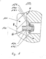
- the invention is a single figure attached 1, which shows a cross section through the wide side plate of a mold according to the invention.
- the wide side plate 100 is constructed according to the invention in two parts. It consists essentially of a Kokillenbreitadmi front panel 110 and a Kokillenbreitlope Wegplatte 120.
- the Kokillenbreit has a melt facing the hot side H and the hot side facing away from or opposite cold side K. Between both Kokillenbreit, paragraphs (front and back) are sections cooling channels or cooling holes, which are not shown here. The cooling channels or bores can run both in the front, in the back and between the two and ensure the cooling of the mold.
- the Kokillenbreitatablytschplatte 120 is bolted by means of a bolt member 130 against the cold side of Kokillenbreit compositevorderplatte 110.
- the bolt member 130 has a bolt head 132 and engages with its threaded portion passing through a bore in the wide-side mold back plate with a thread G in the mold width-side front plate 110.
- the transverse displacements according to the invention also favors that the sliding disk 140 which is provided between the bolt head 132 and the Kokillenbreitrise 120, with a thin sliding layer 142 is formed.
- the sliding layer can consist, for example, of tungsten carbide (WC), diamond like carbon (DLC), boron nitride (BN) or another material that can be deposited by means of physical vapor deposition, Chemical vapor deposition or can be applied by means of a plasma coating process as a thin layer on the base material.
- the sliding layer 142 has the above-mentioned advantageous properties.
- the sliding layer is located at least on the Kokillenbreitetter Wegwarelessness faced side of the sliding disk. Alternatively, the sliding layer can also cover the entire pane (manufacturing is easier).
- a tensioning disk 150 can be provided between the bolt head 132 and the sliding disk 140.
- the bolt member 130 may be formed either as a screw, wherein the bolt head is then formed as a screw head.
- the bolt element may be formed as a metal pin which has a thread at least at its two ends. With its one end, the metal pin engages in a thread in the Kokillenbreitratevorderplatte 110, while at its other end carries a threaded nut, which represents the bolt head 132.
- the chill broadside front plate 110 is made of copper and the chill wide side back plate 120 is made of steel.
Landscapes
- Engineering & Computer Science (AREA)
- Mechanical Engineering (AREA)
- Moulds For Moulding Plastics Or The Like (AREA)
- Continuous Casting (AREA)
- Electroplating Methods And Accessories (AREA)
Abstract
Description
- Die Erfindung betrifft eine Breitseitenplatte einer Kokille zum Stranggießen von Metall.
- Aus der
europäischen Patentanmeldung EP 1 398 099 A1 ist eine Kokille mit einer derartigen Breitseitenplatte grundsätzlich bekannt. Die dort offenbarte Breitseitenplatte ist zweiteilig aufgebaut und umfasst eine Kokillenbreitseitenvorderplatte mit einer der Metallschmelze zugewandten Heißseite und einer der Schmelze abgewandten Kaltseite. Neben der Vorderplatte umfasst die Breitseitenplatte auch eine Kokillenbreitseitenrückplatte. Die Kokillenbreitseitenrückplatte ist mit Hilfe einer Vielzahl von Bolzenelementen in Form von Schrauben an die Kaltseite der Kokillenbreitseitenvorderplatte angeschraubt. Zwischen den Köpfen dieser Schrauben und der Kokillenbreitseitenrückplatte ist jeweils eine Gleitscheibe vorgesehen, welche auf ihrer der Kokillenbreitseitenrückplatte zugewandten Seite eine Polytetraflurethylen PTFE-Beschichtung oder eine separate Gleitscheibe aus PTFE mit einem geringen Reibungskoeffizienten aufweist. - Der Nachteil bei der Verwendung von PTFE für diesen Einsatzzweck liegt darin, dass PTFE unter Last kriecht und damit die Vorspannung der Befestigungselemente verloren geht und sich die Platte lösen kann.
- Ausgehend von diesem Stand der Technik liegt der Erfindung die Aufgabe zugrunde, eine alternative Gleitschicht für eine Gleitscheibe bei einer Breitseitenplatte einer Kokille bereitzustellen.
- Diese Aufgabe wird durch den Gegenstand des Patentanspruchs 1 gelöst. Demnach ist die Gleitschicht (142) aus einem Material gefertigt, welches mit einem der Beschichtungsverfahren Physical-Vapour-Deposition (PVD), Chemical-Vapour-Deposition (CVD) oder einem Plasma-Beschichtungs-Verfahren auf die Gleitscheibe auftragbar ist.
- Deartige Materialen, vorzugsweise Wolfram-Karbid (WC), Diamond Like Carbon (DLC) oder Bor-Nitrid (BN), sind gerade für den beanspruchten Einsatzzweckbereich bei einer Kokille besonders gut geeignet, weil es die drei materialspezifischen Eigenschaften geringer Reibungskoeffizient, hohe Festigkeit, insbesondere Druckfestigkeit und hohe Temperaturstabilität in sich vereinigt. Der geringe Reibungskoeffizient ermöglicht vorteilhafterweise Relativbewegungen, insbesondere Querverschiebungen der Kokillenbreitseitenrückplatte gegenüber dem Bolzenelement, wie sie insbesondere aufgrund von Temperaturunterschieden zwischen Kokillenvorder- und -rückplatte können. Die hohe Festigkeit der Gleitschicht aus den genannten Materialien verhindert einen schnellen Verschleiß der Gleitschicht, insbesondere bei den regelmäßig auftretenden Querverschiebungen. Außerdem hat die hohe Druckfestigkeit den Vorteil, dass sich die Vorspannung nicht verringert. Und schließlich gewährleistet die hohe Temperaturstabilität der genannten Materialien, dass diese Materialien ihre hohe Festigkeit und ihren geringen Reibungskoeffizienten auch bei den hohen Durchschnittstemperaturen von mehr als 100°C, wie sie auch auf der Kaltseite der Kokillenbreitseitenvorderplatte während des Betriebs der Kokille auftreten können, nicht verlieren.
- Gemäß einem ersten vorteilhaften Ausführungsbeispiel ist die Gleitscheibe unterhalb der Gleitschicht gehärtet. Diese Härtung gewährleistet vorteilhafterweise eine hohe Formstabilität der Gleitscheibe bei punktueller Belastung und ebenfalls einen geringen Verschleiß.
- Eine zwischen dem eigentlichen Grundmaterial der Gleitscheibe und ihrer Gleitschicht angebrachte Nickelschicht schützt die Gleitscheibe vor unerwünschter Korrosion.
- Eine optional zwischen den Bolzenkopf und der Gleitscheibe vorgesehene Spannscheibe wirkt als Federelement zum Aufrechterhalten einer notwendigen Vorspannung für die Schraubverbindung zwischen der Kokillenbreitseitenvorderplatte und der Kokillenbreitseitenrückplatte.
- Das Bolzenelement kann als Schraube ausgebildet sein, wobei der Bolzenkopf dann den Schraubenkopf repräsentiert. Alternativ kann das Bolzenelement auch als Gewindestange ausgebildet sein, wobei der Bolzenkopf dann als Mutter für das Gewinde ausgebildet ist.
- Eine Ausbildung der Kokillenbreitseitenvorderplatte aus Kupfer gewährleistet eine hohe Wärmeleitfähigkeit, was zum Abführen der Wärme der Schmelze besonders vorteilhaft und notwendig ist. Dem gegenüber sind die Materialkosten für die Kokillenbreitseitenrückplatte deutlich geringer, wenn diese nicht aus Kupfer, sondern aus Stahl gefertigt ist; die hohe Wärmeleitfähigkeit, wie sie von der Kokillenbreitseitenvorderplatte gefordert wird, ist bei der Kokillenbreitseitenrückplatte nicht mehr erforderlich.
- Der Erfindung ist eine einzige Figur 1 beigefügt, welche einen Querschnitt durch die erfindungsgemäße Breitseitenplatte einer Kokille zeigt.
- Es ist zu erkennen, dass die Breitseitenplatte 100 erfindungsgemäß zweiteilig aufgebaut ist. Sie besteht im Wesentlichen aus einer Kokillenbreitseitenvorderplatte 110 und einer Kokillenbreitseitenrückplatte 120. Die Kokillenbreitseitenvorderplatte 110 besitzt eine der Schmelze zugewandte Heißseite H und eine der Heißseite abgewandte bzw. gegenüberliegende Kaltseite K. Zwischen beiden Kokillenbreitseitenplatten (Vorder- und Rückseite) befinden sich abschnittweise Kühlkanäle oder Kühlbohrungen, die hier nicht gezeigt sind. Die Kühlkanäle oder -bohrungen können sowohl in der Vorderseite, in der Rückseite als auch zwischen beiden verlaufen und sorgen für die Kühlung der Kokille. Die Kokillenbreitseitenrückplatte 120 ist mit Hilfe eines Bolzenelementes 130 gegen die Kaltseite der Kokillenbreitseitenvorderplatte 110 verschraubt. Das Bolzenelement 130 weist einen Bolzenkopf 132 auf und steht mit seinem durch eine Bohrung in der Kokillenbreitseitenrückplatte geführten Gewindeteil mit einem Gewinde G in der Kokillenbreitseitenvorderplatte 110 in Eingriff.
- Aufgrund von großen Temperaturunterschieden, denen besonders die Kokillenbreitseitenvorderplatte ausgesetzt ist, und aufgrund von unterschiedlichen Material-Ausdehnungskoeffizienten der Vorderplatte und der Rückplatte, erfolgen örtlich unterschiedliche Querverschiebungen der Kokillenbreitseitenrückplatte gegenüber dem Bolzenelement 130 und/oder gegenüber der Kokillenbreitseitenvorderplatte 110. Diese Querverschiebungen sollen durch die beanspruchte Konstruktion der Verbindung zwischen der Rückplatte 120 und der Vorderplatte 110 ausdrücklich ermöglicht bzw. zugelassen sein, um unerwünschte Spannungen in den Platten zu vermeiden. Zu diesem Zweck ist zum einen die Bohrung in der Kokillenbreitseitenrückplatte 120 deutlich größer ausgebildet als der Durchmesser des Bolzenelementes 130; auf diese Weise wird ein ausreichendes Spiel für die Querverschiebungen bereit gestellt; siehe Figur 1. Weiterhin werden die Querverschiebungen erfindungsgemäß auch dadurch begünstigt, dass die Gleitscheibe 140, welche zwischen dem Bolzenkopf 132 und der Kokillenbreitseitenrückplatte 120 vorgesehen ist, mit einer dünnen Gleitschicht 142 ausgebildet ist. Die Gleitschicht kann z.B. aus Wolfram-Karbid (WC), Diamond Like Carbon (DLC), Bor-Nitrid (BN) oder einem anderen Material bestehen, das mittels Physical-Vapour-Deposition, Chemical-Vapour-Deposition oder mittels eines Plasma-Beschichtungs-Verfahrens als dünne Schicht auf das Grundmaterial aufgebracht werden kann.
- Die Gleitschicht 142 besitzt die oben genannten vorteilhaften Eigenschaften.
- Die Gleitschicht befindet sich zumindest auf der der Kokillenbreitseitenrückplatte zugewandten Seite der Gleitscheibe. Alternativ kann die Gleitschicht auch die gesamte Scheibe bedecken (Herstellung ist einfacher).
- Optional kann zwischen dem Bolzenkopf 132 und der Gleitscheibe 140 eine Spannscheibe 150 vorgesehen sein. Das Bolzenelement 130 kann entweder als Schraube ausgebildet sein, wobei der Bolzenkopf dann als Schraubenkopf ausgebildet ist. Alternativ kann das Bolzenelement als Metallstift ausgebildet sein, der zumindest an seinen beiden Enden ein Gewinde aufweist. Mit seinem einen Ende greift dann der Metallstift in ein Gewinde in der Kokillenbreitseitenvorderplatte 110 ein, während er an seinem anderen Ende eine Gewinde-Mutter trägt, die den Bolzenkopf 132 repräsentiert.
- Vorteilhafterweise ist die Kokillenbreitseitenvorderplatte 110 aus Kupfer und die Kokillenbreitseitenrückplatte 120 aus Stahl gebildet.
Claims (7)
- Breitseitenplatte (100) einer Kokille zum Stranggießen von Metall, umfassend:eine Kokillenbreitseitenvorderplatte (110);eine Kokillenbreitseitenrückplatte (120);mindestens ein Bolzenelement (130) mit einem Bolzenkopf (132) zum Verbinden der Kokillenbreitseitenrückplatte (120) mit der Kaltseite (K) der Kokillenbreitseitenvorderplatte (110); undeine Gleitscheibe (140), welche zwischen dem Bolzenkopf (132) und der Kokillenbreitseitenrückplatte (120) vorgesehen ist und zumindest auf ihrer der Kokillenbreitseitenrückplatte zugewandten Seite eine Gleitschicht (142) aufweist zum Ermöglichen von reibungsarmen Querverschiebungen der Kokillenbreitseitenrückplatte (120) gegenüber dem Bolzenelement (130);dadurch gekennzeichnet,
dass die Gleitschicht (142) aus einem Material gefertigt ist, welches mit einem der Beschichtungsverfahren Physical-Vapour-Deposition (PVD), Chemical-Vapour-Deposition (CVD) oder einem Plasma-Beschichtungs-Verfahren auf die Gleitscheibe auftragbar ist. - Breitseitenplatte (100) nach Anspruch 1,
dadurch gekennzeichnet,
dass es sich bei dem Material um Diamond Like Carbon oder um ein keramisches Material, wie zum Beispiel Wolfram-Karbid oder Bor-Nitrid handelt. - Breitseitenplatte (100) nach einem der vorangegangenen Ansprüche,
dadurch gekennzeichnet,
dass die Gleitscheibe (140) gehärtet ist. - Breitseitenplatte (100) nach einem der vorangegangenen Ansprüche,
dadurch gekennzeichnet,
dass die Gleitscheibe (140) mit einer Nickelschicht vernicket ist und dass die Gleitschicht (142) außen auf die Nickelschicht aufgetragen ist. - Breitseitenplatte (100) nach einem der vorangegangenen Ansprüche,
dadurch gekennzeichnet,
dass zwischen dem Bolzenkopf (132) und der Gleitscheibe (140) eine Spannscheibe (150) vorgesehen ist. - Breitseitenplatte (100) nach einem der vorangegangenen Ansprüche,
dadurch gekennzeichnet,
dass das Bolzenelement (130) als Schraube und der Bolzenkopf (132) als Schraubenkopf der Schraube ausgebildet ist. - Breitseitenplatte (100) nach einem der vorangegangenen Ansprüche,
dadurch gekennzeichnet,
dass die Kokillenbreitseitenvorderplatte (110) aus Kupfer und die Kokillenbreitseitenrückplatte (120) aus Stahl, vorzugsweise aus unlegiertem Kohlenstoffstahl, gebildet ist.
Applications Claiming Priority (1)
| Application Number | Priority Date | Filing Date | Title |
|---|---|---|---|
| DE102006039719A DE102006039719A1 (de) | 2006-08-24 | 2006-08-24 | Breitseitenplatte einer Kokille |
Publications (2)
| Publication Number | Publication Date |
|---|---|
| EP1892050A1 true EP1892050A1 (de) | 2008-02-27 |
| EP1892050B1 EP1892050B1 (de) | 2011-03-23 |
Family
ID=38776283
Family Applications (1)
| Application Number | Title | Priority Date | Filing Date |
|---|---|---|---|
| EP07015168A Not-in-force EP1892050B1 (de) | 2006-08-24 | 2007-08-02 | Vorrichtung zum Stranggiessen von Metall |
Country Status (4)
| Country | Link |
|---|---|
| EP (1) | EP1892050B1 (de) |
| AT (1) | ATE502707T1 (de) |
| DE (2) | DE102006039719A1 (de) |
| ES (1) | ES2360821T3 (de) |
Citations (3)
| Publication number | Priority date | Publication date | Assignee | Title |
|---|---|---|---|---|
| DE10011221A1 (de) | 2000-03-08 | 2001-09-13 | Volkswagen Ag | Druckgießform |
| EP1398099A1 (de) | 2002-08-16 | 2004-03-17 | KM Europa Metal Aktiengesellschaft | Flüssigkeitsgekühlte Kokille zum Stranggiessen von Metallen |
| DE102004033321A1 (de) | 2004-07-09 | 2006-02-02 | Brueninghaus Hydromatik Gmbh | Axialkolbenmaschine mit Verschleißschutzschicht |
-
2006
- 2006-08-24 DE DE102006039719A patent/DE102006039719A1/de not_active Withdrawn
-
2007
- 2007-08-02 ES ES07015168T patent/ES2360821T3/es active Active
- 2007-08-02 DE DE502007006757T patent/DE502007006757D1/de active Active
- 2007-08-02 AT AT07015168T patent/ATE502707T1/de active
- 2007-08-02 EP EP07015168A patent/EP1892050B1/de not_active Not-in-force
Patent Citations (3)
| Publication number | Priority date | Publication date | Assignee | Title |
|---|---|---|---|---|
| DE10011221A1 (de) | 2000-03-08 | 2001-09-13 | Volkswagen Ag | Druckgießform |
| EP1398099A1 (de) | 2002-08-16 | 2004-03-17 | KM Europa Metal Aktiengesellschaft | Flüssigkeitsgekühlte Kokille zum Stranggiessen von Metallen |
| DE102004033321A1 (de) | 2004-07-09 | 2006-02-02 | Brueninghaus Hydromatik Gmbh | Axialkolbenmaschine mit Verschleißschutzschicht |
Also Published As
| Publication number | Publication date |
|---|---|
| DE502007006757D1 (de) | 2011-05-05 |
| DE102006039719A1 (de) | 2008-02-28 |
| ATE502707T1 (de) | 2011-04-15 |
| ES2360821T3 (es) | 2011-06-09 |
| EP1892050B1 (de) | 2011-03-23 |
Similar Documents
| Publication | Publication Date | Title |
|---|---|---|
| DE3625056C2 (de) | Feuerfeste Auskleidung, insbesondere für Brennkammern von Gasturbinenanlagen | |
| EP1398099B1 (de) | Flüssigkeitsgekühlte Kokille zum Stranggiessen von Metallen | |
| CH654759A5 (de) | Zentrifugensieb. | |
| DE4328778A1 (de) | Schneidleiste mit einer Schneidschicht aus hochverschleißfestem Material | |
| DE10356937A1 (de) | Düsenspitze und -dichtung | |
| EP2996849B1 (de) | Extrusionskopf mit lochplatte einer granulieranlage | |
| DE60124518T2 (de) | Herstellungsverfahren eines kühlelements und kühlelement | |
| EP1128100A1 (de) | Bürste für eine Bürstendichtung | |
| EP1892050B1 (de) | Vorrichtung zum Stranggiessen von Metall | |
| DE202006011535U1 (de) | Schneidplatte | |
| EP2483017B1 (de) | Giessform | |
| EP1817528B1 (de) | Verfahren zur herstellung eines hitzeschildelementes | |
| DE10114720A1 (de) | Kühlplatte | |
| EP2248984A2 (de) | Fassade, insbesondere Glasfassade | |
| WO2007137445A1 (de) | Bauteil aus zwei kraftschlüssig verbundenen werkstücken | |
| DE102013106257A1 (de) | Bauteil für eine Spritzgießmaschine | |
| EP0987073A1 (de) | Kokillenwand einer Stranggiesskokille | |
| DE4041830A1 (de) | Stahlstranggiesskokille | |
| DE202017007128U1 (de) | Horizontale Gießkammer sowie ein Kit mit einer Gießkammer und einer Einfüllhilfe | |
| DE102007028064A1 (de) | Kokillenplatte für eine Kokille einer Stranggießanlage | |
| DE4203595C2 (de) | Vorrichtung zum Abstützen von Einsatzgut in einem Erwärmungsofen | |
| DE102007045289A1 (de) | Verdampferschiffchen, Verfahren zu deren Herstellung sowie deren Verwendung | |
| DE102006060775A1 (de) | Keilbremse für ein Kraftfahrzeug und Verfahren zur Herstellung einer Keilbremse | |
| AT505331B1 (de) | Werkzeug zum umformen eines werkstückes, insbesondere schmiedewerkzeug | |
| DE19926585B4 (de) | Konstruktionselement in Hybridbauweise |
Legal Events
| Date | Code | Title | Description |
|---|---|---|---|
| PUAI | Public reference made under article 153(3) epc to a published international application that has entered the european phase |
Free format text: ORIGINAL CODE: 0009012 |
|
| AK | Designated contracting states |
Kind code of ref document: A1 Designated state(s): AT BE BG CH CY CZ DE DK EE ES FI FR GB GR HU IE IS IT LI LT LU LV MC MT NL PL PT RO SE SI SK TR |
|
| AX | Request for extension of the european patent |
Extension state: AL BA HR MK YU |
|
| 17P | Request for examination filed |
Effective date: 20080731 |
|
| AKX | Designation fees paid |
Designated state(s): AT BE BG CH CY CZ DE DK EE ES FI FR GB GR HU IE IS IT LI LT LU LV MC MT NL PL PT RO SE SI SK TR |
|
| 17Q | First examination report despatched |
Effective date: 20081121 |
|
| RAP1 | Party data changed (applicant data changed or rights of an application transferred) |
Owner name: SMS SIEMAG AG |
|
| GRAP | Despatch of communication of intention to grant a patent |
Free format text: ORIGINAL CODE: EPIDOSNIGR1 |
|
| RTI1 | Title (correction) |
Free format text: DEVICE FOR THE CONTINUOUS CASTING OF METAL |
|
| GRAS | Grant fee paid |
Free format text: ORIGINAL CODE: EPIDOSNIGR3 |
|
| GRAA | (expected) grant |
Free format text: ORIGINAL CODE: 0009210 |
|
| AK | Designated contracting states |
Kind code of ref document: B1 Designated state(s): AT BE BG CH CY CZ DE DK EE ES FI FR GB GR HU IE IS IT LI LT LU LV MC MT NL PL PT RO SE SI SK TR |
|
| REG | Reference to a national code |
Ref country code: GB Ref legal event code: FG4D Free format text: NOT ENGLISH |
|
| REG | Reference to a national code |
Ref country code: CH Ref legal event code: EP |
|
| REG | Reference to a national code |
Ref country code: IE Ref legal event code: FG4D |
|
| REF | Corresponds to: |
Ref document number: 502007006757 Country of ref document: DE Date of ref document: 20110505 Kind code of ref document: P |
|
| REG | Reference to a national code |
Ref country code: DE Ref legal event code: R096 Ref document number: 502007006757 Country of ref document: DE Effective date: 20110505 |
|
| REG | Reference to a national code |
Ref country code: ES Ref legal event code: FG2A Ref document number: 2360821 Country of ref document: ES Kind code of ref document: T3 Effective date: 20110609 |
|
| REG | Reference to a national code |
Ref country code: NL Ref legal event code: VDEP Effective date: 20110323 |
|
| PG25 | Lapsed in a contracting state [announced via postgrant information from national office to epo] |
Ref country code: GR Free format text: LAPSE BECAUSE OF FAILURE TO SUBMIT A TRANSLATION OF THE DESCRIPTION OR TO PAY THE FEE WITHIN THE PRESCRIBED TIME-LIMIT Effective date: 20110624 Ref country code: LT Free format text: LAPSE BECAUSE OF FAILURE TO SUBMIT A TRANSLATION OF THE DESCRIPTION OR TO PAY THE FEE WITHIN THE PRESCRIBED TIME-LIMIT Effective date: 20110323 Ref country code: LV Free format text: LAPSE BECAUSE OF FAILURE TO SUBMIT A TRANSLATION OF THE DESCRIPTION OR TO PAY THE FEE WITHIN THE PRESCRIBED TIME-LIMIT Effective date: 20110323 Ref country code: SE Free format text: LAPSE BECAUSE OF FAILURE TO SUBMIT A TRANSLATION OF THE DESCRIPTION OR TO PAY THE FEE WITHIN THE PRESCRIBED TIME-LIMIT Effective date: 20110323 |
|
| LTIE | Lt: invalidation of european patent or patent extension |
Effective date: 20110323 |
|
| PG25 | Lapsed in a contracting state [announced via postgrant information from national office to epo] |
Ref country code: FI Free format text: LAPSE BECAUSE OF FAILURE TO SUBMIT A TRANSLATION OF THE DESCRIPTION OR TO PAY THE FEE WITHIN THE PRESCRIBED TIME-LIMIT Effective date: 20110323 Ref country code: CY Free format text: LAPSE BECAUSE OF FAILURE TO SUBMIT A TRANSLATION OF THE DESCRIPTION OR TO PAY THE FEE WITHIN THE PRESCRIBED TIME-LIMIT Effective date: 20110323 Ref country code: BG Free format text: LAPSE BECAUSE OF FAILURE TO SUBMIT A TRANSLATION OF THE DESCRIPTION OR TO PAY THE FEE WITHIN THE PRESCRIBED TIME-LIMIT Effective date: 20110623 Ref country code: SI Free format text: LAPSE BECAUSE OF FAILURE TO SUBMIT A TRANSLATION OF THE DESCRIPTION OR TO PAY THE FEE WITHIN THE PRESCRIBED TIME-LIMIT Effective date: 20110323 |
|
| REG | Reference to a national code |
Ref country code: IE Ref legal event code: FD4D |
|
| PG25 | Lapsed in a contracting state [announced via postgrant information from national office to epo] |
Ref country code: EE Free format text: LAPSE BECAUSE OF FAILURE TO SUBMIT A TRANSLATION OF THE DESCRIPTION OR TO PAY THE FEE WITHIN THE PRESCRIBED TIME-LIMIT Effective date: 20110323 Ref country code: PT Free format text: LAPSE BECAUSE OF FAILURE TO SUBMIT A TRANSLATION OF THE DESCRIPTION OR TO PAY THE FEE WITHIN THE PRESCRIBED TIME-LIMIT Effective date: 20110725 |
|
| PG25 | Lapsed in a contracting state [announced via postgrant information from national office to epo] |
Ref country code: IS Free format text: LAPSE BECAUSE OF FAILURE TO SUBMIT A TRANSLATION OF THE DESCRIPTION OR TO PAY THE FEE WITHIN THE PRESCRIBED TIME-LIMIT Effective date: 20110723 Ref country code: RO Free format text: LAPSE BECAUSE OF FAILURE TO SUBMIT A TRANSLATION OF THE DESCRIPTION OR TO PAY THE FEE WITHIN THE PRESCRIBED TIME-LIMIT Effective date: 20110323 Ref country code: CZ Free format text: LAPSE BECAUSE OF FAILURE TO SUBMIT A TRANSLATION OF THE DESCRIPTION OR TO PAY THE FEE WITHIN THE PRESCRIBED TIME-LIMIT Effective date: 20110323 Ref country code: SK Free format text: LAPSE BECAUSE OF FAILURE TO SUBMIT A TRANSLATION OF THE DESCRIPTION OR TO PAY THE FEE WITHIN THE PRESCRIBED TIME-LIMIT Effective date: 20110323 |
|
| PG25 | Lapsed in a contracting state [announced via postgrant information from national office to epo] |
Ref country code: MT Free format text: LAPSE BECAUSE OF FAILURE TO SUBMIT A TRANSLATION OF THE DESCRIPTION OR TO PAY THE FEE WITHIN THE PRESCRIBED TIME-LIMIT Effective date: 20110323 Ref country code: NL Free format text: LAPSE BECAUSE OF FAILURE TO SUBMIT A TRANSLATION OF THE DESCRIPTION OR TO PAY THE FEE WITHIN THE PRESCRIBED TIME-LIMIT Effective date: 20110323 |
|
| PLBE | No opposition filed within time limit |
Free format text: ORIGINAL CODE: 0009261 |
|
| STAA | Information on the status of an ep patent application or granted ep patent |
Free format text: STATUS: NO OPPOSITION FILED WITHIN TIME LIMIT |
|
| PG25 | Lapsed in a contracting state [announced via postgrant information from national office to epo] |
Ref country code: IE Free format text: LAPSE BECAUSE OF FAILURE TO SUBMIT A TRANSLATION OF THE DESCRIPTION OR TO PAY THE FEE WITHIN THE PRESCRIBED TIME-LIMIT Effective date: 20110323 |
|
| 26N | No opposition filed |
Effective date: 20111227 |
|
| BERE | Be: lapsed |
Owner name: SMS SIEMAG AG Effective date: 20110831 |
|
| PG25 | Lapsed in a contracting state [announced via postgrant information from national office to epo] |
Ref country code: PL Free format text: LAPSE BECAUSE OF FAILURE TO SUBMIT A TRANSLATION OF THE DESCRIPTION OR TO PAY THE FEE WITHIN THE PRESCRIBED TIME-LIMIT Effective date: 20110323 Ref country code: DK Free format text: LAPSE BECAUSE OF FAILURE TO SUBMIT A TRANSLATION OF THE DESCRIPTION OR TO PAY THE FEE WITHIN THE PRESCRIBED TIME-LIMIT Effective date: 20110323 |
|
| PG25 | Lapsed in a contracting state [announced via postgrant information from national office to epo] |
Ref country code: MC Free format text: LAPSE BECAUSE OF NON-PAYMENT OF DUE FEES Effective date: 20110831 |
|
| REG | Reference to a national code |
Ref country code: CH Ref legal event code: PL |
|
| REG | Reference to a national code |
Ref country code: DE Ref legal event code: R097 Ref document number: 502007006757 Country of ref document: DE Effective date: 20111227 |
|
| PG25 | Lapsed in a contracting state [announced via postgrant information from national office to epo] |
Ref country code: LI Free format text: LAPSE BECAUSE OF NON-PAYMENT OF DUE FEES Effective date: 20110831 Ref country code: CH Free format text: LAPSE BECAUSE OF NON-PAYMENT OF DUE FEES Effective date: 20110831 |
|
| REG | Reference to a national code |
Ref country code: FR Ref legal event code: ST Effective date: 20120430 |
|
| PG25 | Lapsed in a contracting state [announced via postgrant information from national office to epo] |
Ref country code: BE Free format text: LAPSE BECAUSE OF NON-PAYMENT OF DUE FEES Effective date: 20110831 |
|
| PG25 | Lapsed in a contracting state [announced via postgrant information from national office to epo] |
Ref country code: FR Free format text: LAPSE BECAUSE OF NON-PAYMENT OF DUE FEES Effective date: 20110831 |
|
| PG25 | Lapsed in a contracting state [announced via postgrant information from national office to epo] |
Ref country code: LU Free format text: LAPSE BECAUSE OF NON-PAYMENT OF DUE FEES Effective date: 20110802 |
|
| PG25 | Lapsed in a contracting state [announced via postgrant information from national office to epo] |
Ref country code: TR Free format text: LAPSE BECAUSE OF FAILURE TO SUBMIT A TRANSLATION OF THE DESCRIPTION OR TO PAY THE FEE WITHIN THE PRESCRIBED TIME-LIMIT Effective date: 20110323 |
|
| PG25 | Lapsed in a contracting state [announced via postgrant information from national office to epo] |
Ref country code: HU Free format text: LAPSE BECAUSE OF FAILURE TO SUBMIT A TRANSLATION OF THE DESCRIPTION OR TO PAY THE FEE WITHIN THE PRESCRIBED TIME-LIMIT Effective date: 20110323 |
|
| REG | Reference to a national code |
Ref country code: DE Ref legal event code: R082 Ref document number: 502007006757 Country of ref document: DE Representative=s name: HEMMERICH & KOLLEGEN, DE Ref country code: DE Ref legal event code: R081 Ref document number: 502007006757 Country of ref document: DE Owner name: SMS GROUP GMBH, DE Free format text: FORMER OWNER: SMS SIEMAG AG, 40237 DUESSELDORF, DE |
|
| PGFP | Annual fee paid to national office [announced via postgrant information from national office to epo] |
Ref country code: DE Payment date: 20200819 Year of fee payment: 14 Ref country code: GB Payment date: 20200826 Year of fee payment: 14 |
|
| PGFP | Annual fee paid to national office [announced via postgrant information from national office to epo] |
Ref country code: IT Payment date: 20200826 Year of fee payment: 14 Ref country code: AT Payment date: 20200820 Year of fee payment: 14 |
|
| PGFP | Annual fee paid to national office [announced via postgrant information from national office to epo] |
Ref country code: ES Payment date: 20201023 Year of fee payment: 14 |
|
| REG | Reference to a national code |
Ref country code: DE Ref legal event code: R119 Ref document number: 502007006757 Country of ref document: DE |
|
| REG | Reference to a national code |
Ref country code: AT Ref legal event code: MM01 Ref document number: 502707 Country of ref document: AT Kind code of ref document: T Effective date: 20210802 |
|
| GBPC | Gb: european patent ceased through non-payment of renewal fee |
Effective date: 20210802 |
|
| PG25 | Lapsed in a contracting state [announced via postgrant information from national office to epo] |
Ref country code: AT Free format text: LAPSE BECAUSE OF NON-PAYMENT OF DUE FEES Effective date: 20210802 |
|
| PG25 | Lapsed in a contracting state [announced via postgrant information from national office to epo] |
Ref country code: IT Free format text: LAPSE BECAUSE OF NON-PAYMENT OF DUE FEES Effective date: 20210802 Ref country code: GB Free format text: LAPSE BECAUSE OF NON-PAYMENT OF DUE FEES Effective date: 20210802 Ref country code: DE Free format text: LAPSE BECAUSE OF NON-PAYMENT OF DUE FEES Effective date: 20220301 |
|
| REG | Reference to a national code |
Ref country code: ES Ref legal event code: FD2A Effective date: 20220929 |
|
| PG25 | Lapsed in a contracting state [announced via postgrant information from national office to epo] |
Ref country code: ES Free format text: LAPSE BECAUSE OF NON-PAYMENT OF DUE FEES Effective date: 20210803 |