EP1892011B1 - Implant électromédical - Google Patents
Implant électromédical Download PDFInfo
- Publication number
- EP1892011B1 EP1892011B1 EP07014652.7A EP07014652A EP1892011B1 EP 1892011 B1 EP1892011 B1 EP 1892011B1 EP 07014652 A EP07014652 A EP 07014652A EP 1892011 B1 EP1892011 B1 EP 1892011B1
- Authority
- EP
- European Patent Office
- Prior art keywords
- signal
- waking
- transceiver
- control unit
- transmission
- Prior art date
- Legal status (The legal status is an assumption and is not a legal conclusion. Google has not performed a legal analysis and makes no representation as to the accuracy of the status listed.)
- Not-in-force
Links
Images
Classifications
-
- A—HUMAN NECESSITIES
- A61—MEDICAL OR VETERINARY SCIENCE; HYGIENE
- A61N—ELECTROTHERAPY; MAGNETOTHERAPY; RADIATION THERAPY; ULTRASOUND THERAPY
- A61N1/00—Electrotherapy; Circuits therefor
- A61N1/18—Applying electric currents by contact electrodes
- A61N1/32—Applying electric currents by contact electrodes alternating or intermittent currents
- A61N1/36—Applying electric currents by contact electrodes alternating or intermittent currents for stimulation
- A61N1/372—Arrangements in connection with the implantation of stimulators
- A61N1/37211—Means for communicating with stimulators
- A61N1/37252—Details of algorithms or data aspects of communication system, e.g. handshaking, transmitting specific data or segmenting data
- A61N1/37276—Details of algorithms or data aspects of communication system, e.g. handshaking, transmitting specific data or segmenting data characterised by means for reducing power consumption during telemetry
-
- A—HUMAN NECESSITIES
- A61—MEDICAL OR VETERINARY SCIENCE; HYGIENE
- A61N—ELECTROTHERAPY; MAGNETOTHERAPY; RADIATION THERAPY; ULTRASOUND THERAPY
- A61N1/00—Electrotherapy; Circuits therefor
- A61N1/18—Applying electric currents by contact electrodes
- A61N1/32—Applying electric currents by contact electrodes alternating or intermittent currents
- A61N1/36—Applying electric currents by contact electrodes alternating or intermittent currents for stimulation
- A61N1/372—Arrangements in connection with the implantation of stimulators
- A61N1/37211—Means for communicating with stimulators
- A61N1/37252—Details of algorithms or data aspects of communication system, e.g. handshaking, transmitting specific data or segmenting data
- A61N1/37288—Communication to several implantable medical devices within one patient
Definitions
- the invention relates to an implantable medical device having a built-in transceiver for wirelessly transmitting and receiving data that can be disabled between individual data transmissions.
- Such implantable medical devices may be, for example, pacemakers or cardioverter / defibrillators or combinations of both.
- a variety of such implants are known, which have a transmitter / receiver, ie a transceiver, with the help of which it is possible to transfer physiological or technical data or both from the implant to an external device or vice versa using an external device data for Implant to transfer. The latter may be desirable, for example, for programming the implant or else to query specific data.
- Such transmitter / receiver are eg off WO 2005 / 099817A and US 2006 / 122667A1 known.
- multiple implants may be within range of one another or within range of one or more external devices.
- the object of the invention is to provide an implant which is suitable for the aforementioned scenario and as energy-saving as possible.
- the invention relates to an implant with the features of claim 1. According to the invention this object is achieved by an implant of the type mentioned above, which has a waking unit in addition to the transceiver, which is adapted to the transceiver from its idle state or from its off state, in He needs little or no energy to switch to its fully operational state, where he needs more energy.
- the wake-up unit has a second, separate low-power receiver which has a significantly lower energy requirement than the transceiver in its switched-on or fully operational state.
- the wake-up unit has a wake-up control unit which is connected to an output of the low power receiver.
- EP 1353447A and WO 2006 / 062644A disclose such low power receivers that monitor a single frequency.
- the low-power receiver is designed to monitor a plurality of predetermined frequency ranges such that it generates an output signal in the event of a transmission of sufficient signal strength in one or more of the frequency ranges and outputs it to the wake-up control unit.
- the wake-up control unit is designed to evaluate output signals of the low-power receiver and to output a wake-up signal to the transceiver, which switches this on or fully operational, if a predetermined condition is fulfilled or a plurality of predetermined conditions are met.
- the wake-up control unit is designed such that it emits a wake-up signal to the transceiver when the low-power receiver emits a series of output signals which indicate that the low-power receiver has detected a sequence of transmissions of sufficient signal strength in different frequency ranges, that of a given sequence or Match order.
- the predetermined sequence may be such that the output signals are transmissions in the frequency ranges C, A, B, D (in that order). mark.
- Such a sequence of transmissions in different frequency ranges is also referred to below as a trigger signal sequence, since such a sequence of transmissions is intended to trigger the switching on of the transceiver.
- the order of the output signals of the low power receiver thus always characterizes a respective frequency scheme.
- a frequency scheme serves as a kind of key for switching on the transceiver of a corresponding preset or programmed implant.
- the low-power receiver preferably has a plurality of band-pass filters whose passband is adapted to the predetermined frequency ranges. Associated with each bandpass filter is a signal detector cooperating with the respective bandpass filter such that the signal detector outputs a signal when the low power receiver in a respective frequency range corresponding to a passband of the bandpass filter to which the signal detector is assigned transmits with sufficient signal strength receives.
- a low power receiver is at the output of a respective signal detector before an output signal for transmission to the wake-up control unit, as soon as the low power receiver receives a transmission of sufficient signal strength in the respective frequency range. In this way, the low power generates Receiver Signals or signal sequences that are to be further processed by the wake-up control unit.
- the wake-up control unit is designed to detect the sequence of the signals output by the signal detectors and to compare them with a predetermined sequence in order to deliver the wake-up signal to the transceiver in the case of a positive comparison (the received signal sequence corresponds to the predetermined order).
- the wake-up control unit may have a time monitoring unit and be designed to generate the wake-up signal only if the signals output by the signal detectors occur in succession within a predetermined period of time.
- the predetermined period of time can be a total period of time within which all signals must have occurred and it can also be given a plurality of time periods that describe until when a subsequent signal must follow the respective preceding signal.
- the transceiver can be switched by receiving a trigger signal sequence of a switched off or a power-saving mode in an on or fully operational mode, without the need to receive a signal with sufficiently good quality to the signal to be able to decode. Therefore, a simple receiver is sufficient as a low power receiver with low energy consumption. Nevertheless, a targeted response of a corresponding preset implant is possible, even without that first, for example, corresponding address data in a received signal must be decoded and evaluated.
- Another aspect relates to the reaction of the implant to the receipt of a trigger signal or a trigger signal sequence. For example, if a plurality of implants are addressed simultaneously by a trigger signal sequence, this could result in all of the addressed Implants simultaneously emit a response signal to the carrier signal sequence, so that at least for the majority of implants successful communication with an external device is not possible.
- the implantable medical device preferably has a transmission control unit which has a random generator or is connected to it and is designed to emit a response signal after expiry of a waiting time after the transceiver is switched on by the wake-up control unit and, at the same time, the time a transmission start after switching on the transceiver by the wake-up control unit to determine such that the time of the transmission start corresponds to the end time of the waiting time, which in turn begins with the wake-up signal.
- the waiting time has a duration which corresponds to the product ZZ x SD from a random number ZZ generated by the random number generator and a predetermined, average transmission duration SD.
- the waiting time after which an implant responds to a corresponding trigger signal has a random length, so that it is unlikely that two implants respond to a trigger signal at the same time.
- the random number is scaled to be an integer between 0 and a maximum number of expected implants in the receiving range of an external device minus 1, it is very unlikely that during the transmission duration for the transmission of the response signal of a first implant, a second implant begins to transmit a response signal.
- this time period SD determines a timeslot for the transmission of the response signal. Since all implants in the environment of the external device are woken up by the same trigger signal from the external device or - in a more general embodiment - at least synchronized, the Timeslots, that is the same as a function of the respective random number ZZ consecutively connected transmission end times SD clocked equal.
- the transmission control unit is designed in a preferred embodiment, to repeat the transmission of the response signal after a re-determined waiting time.
- the repetition of the transmission of the response signal may be dependent on whether a respective transmitted response signal remains unanswered or not.
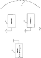
- FIG. 1 1 shows an external device as an external transceiver 10 and two implants 20 'and 20 ", which are located within a reception range of the external device 10 indicated by a dashed line 12.
- the reception range results from the transmission power of the implants 20' and 20 "as well as the sensitivity of the receiver of the external device 10.
- the presented scenario basically results in the problem that the implants each have a transceiver 203 (see FIG. 2 ), which consumes relatively much energy in the transmit and receive mode and therefore should be kept as long as possible and as often in a power saving mode or turned off, but should also be switched by a signal from outside the implant in its fully operational mode. However, this should not happen by signals that come from another implant or completely foreign transmitting device in the receiving range of each device, if possible. If possible, the transceiver 203 of a respective implant should be woken up only by an external device such as the external device 10 as possible.
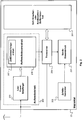
- Imaged implant 20 represents a preferred embodiment of an implant, which takes into account both of the aforementioned problems.
- the implant 20 has a wake-up unit 202, which is connected to the transceiver 203 of the implant 20 and can output to the transceiver 203 a wake-up signal, by which the transceiver 203 from a switched-off state or a power-saving mode in a more energy-consuming, full ready mode can be switched.
- the wake-up signal which the wake-up unit 202 outputs to the transceiver 203, should be able to be triggered wirelessly, but not by any data transmission.
- the reception of the wake-up signal triggering wirelessly transmitting trigger signal should not require as much power as the transceiver requires in 203 in its fully operational state.
- the wake-up unit 202 comprises, in addition to a wake-up control unit 207, which finally generates the wake-up signal, a low power receiver 210, which as a broadband receiver is capable of detecting wireless transmissions of signals in different frequency ranges.
- the low power receiver 210 is capable of detecting transmissions each exceeding a predetermined minimum signal strength in one of a plurality of predetermined frequency ranges and producing an output signal each if it is transmitting in one of the predetermined frequency ranges with a signal strength detected above the predetermined minimum.
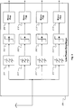
- the low power receiver (see FIG. 3 ) comprise four bandpass filters 211 ', 211 ", 211"' and 211 "", each having a pass band tuned to a frequency range of four frequency ranges in total.
- Each bandpass filter 211 ', 211 ", 211'” and 211 “” is followed in each case by a signal detector 212 ', 213', 212 “, 213", 212 "', 213", 212 "", 213 “”
- Signal detectors include a threshold switch 212 ', 212 ", 212'” and 212 "” responsive to the output of the correspondingly associated bandpass filter 211 ', 211 ", 211 "'or 211"”an output signal is applied to a signal strength which is above the predetermined threshold.” If the respective threshold value switch 212', 212 “, 212 '” or 212 "” responds to such a signal, it triggers a respective, the monostable multivibrator 213 ', 213 ",
- the wake-up control unit 206 is designed to evaluate the output signals of the low-power receiver 210 in two ways.
- the wake-up control unit is designed to compare the order of the output signals of the low-power receiver 210 with a predetermined sequence and to output the wake-up signal to the transceiver 203 only if the order of the output signals of the low-power receiver 210 of the predefined, in the Implant 20 stored order corresponds.
- the wake-up control unit 206 is configured to ensure, with the aid of a time monitoring unit 207, that the wake-up signal is only generated if the output signals of the low-power receiver 210 follow each other not only in the predetermined sequence but also within the respective predetermined time arrive.
- the predetermined order of the signals and the corresponding predetermined times result in a kind of characteristic key, with which, for example, an external device wirelessly a transceiver 203th can specifically wake an implant 20 without the need to decode and evaluate data that could be included as address data in a wirelessly transmitted signal, for example.
- a transmission control unit 204 of the implant 20 is designed to control the transmission of a response signal which the implant 20 emits after receiving a wirelessly transmitted trigger signal which has led via a corresponding wake-up signal to wake up the transceiver 203.
- the transmission control unit is configured to trigger a transmission of the response signal via the transceiver 203 only after expiration of a waiting time, which begins with the waking up of the transceiver 203.
- the transmission control unit 204 calculates this waiting time from a random number ZZ generated by a random generator 205 and a predetermined maximum value for a transmission duration SD for transmitting the response signal B from a likewise predetermined integer AI, which is greater than the maximum number of implants to be expected the range of an external device.
- the waiting time is a product of the integer ZZ and SD: ZZ x SD scaled with AI.
- the respective, so determined waiting time is started upon receipt of the carrier signal and causes the control unit 204 triggers the transmission of the response signal via the receiver 203 at the end of the waiting time.
Landscapes
- Health & Medical Sciences (AREA)
- Engineering & Computer Science (AREA)
- Biomedical Technology (AREA)
- Nuclear Medicine, Radiotherapy & Molecular Imaging (AREA)
- Radiology & Medical Imaging (AREA)
- Life Sciences & Earth Sciences (AREA)
- Animal Behavior & Ethology (AREA)
- General Health & Medical Sciences (AREA)
- Public Health (AREA)
- Veterinary Medicine (AREA)
- Mobile Radio Communication Systems (AREA)
- Electrotherapy Devices (AREA)
- Measuring And Recording Apparatus For Diagnosis (AREA)
Claims (7)
- Appareil médical implantable (20) avec
un émetteur-récepteur (203), pour l'envoi et la réception de données transmises sans fil, qui, entre des transmissions de données individuelles, est à l'arrêt ou dans une position de veille économe en énergie, ainsi qu'avec
une unité de redémarrage (202), qui est configurée pour passer l'émetteur-récepteur (203) de son état d'arrêt ou de son état de veille dans son état de fonctionnement complet par un signal de redémarrage,
où l'unité de redémarrage présente un récepteur à consommation réduite (210) et une unité de commande de redémarrage (206), parmi lesquels, le récepteur à consommation réduite (210) est conçu pour contrôler une multitude de domaines de fréquences prédéfinies de telle sorte que, dans le cas d'une transmission de puissance de signal suffisante dans un ou plusieurs domaines de fréquences, il génère un signal de sortie et le transmet à l'unité de commande de démarrage (206), et parmi lesquels l'unité de commande de démarrage (206) est conçue pour évaluer des signaux de sortie du récepteur à consommation réduite (210) et délivrer un signal de redémarrage à l'émetteur-récepteur (203) qui met celui-ci en marche ou le remet en totale position de fonctionnement,
où l'unité de commande de redémarrage (206) est configurée pour délivrer le signal de redémarrage à l'émetteur-récepteur (203) lorsque la condition est remplie que le récepteur à consommation réduite (210) émet une suite de signaux de sortie qui montrent que le récepteur à consommation réduite (210) a détecté une suite de transmissions de puissance de signal suffisante dans divers domaines de fréquences prédéfinis, qui correspond à une succession ou une série prédéfinies de fréquences, caractérisé en ce que
le récepteur à consommation réduite (210) présente plusieurs filtres de bande passante (211', 211", 211"', 211"") avec chaque fois un domaine de passage adapté aux domaines de fréquences prédéfinis et avec chaque fois un détecteur de signaux (212', 212", 212"', 212"") associé qui agissent conjointement de telle manière qu'un détecteur de signaux (212', 212", 212"', 212"") donné émet un signal de sortie lorsque le récepteur à consommation réduite (210) reçoit une transmission avec une puissance de signal suffisante dans un domaine de fréquences qui correspond à un domaine de passage du filtre de bande passante (211', 211", 211"', 211"") auquel le détecteur de signaux (212', 212", 212"', 212"") donné est associé. - Appareil médical implantable (20) selon la revendication 1, caractérisé en ce que l'unité de commande de redémarrage (206) est configurée pour- détecter la série de signaux émis par les détecteurs de signaux (212', 212", 212"', 212"") et- la comparer avec une série prédéfinie et- transmettre le signal de redémarrage à l'émetteur-récepteur (203) dans le cas d'une comparaison positive.
- Appareil médical implantable (20) selon la revendication 2, caractérisé en ce que l'unité de commande de redémarrage (206) présente une unité de surveillance du temps (207) et est configurée pour générer le signal de redémarrage uniquement lorsque les signaux délivrés par les détecteurs de signaux (212', 212", 212"', 212"") se produisent l'un après l'autre pendant un laps de temps prédéterminé.
- Appareil médical implantable (20) selon la revendication 1, avec une unité de commande d'émetteur (204), caractérisé en ce que l'unité de commande d'émetteur (204) présente un générateur aléatoire (205) ou est reliée avec un tel dispositif et est configurée pour émettre un signal de réponse après l'écoulement d'un temps d'attente après la mise en marche de l'émetteur-récepteur (203) par l'unité de commande de redémarrage (206) et pour déterminer pour cela le moment d'un début d'émission après la mise en marche de l'émetteur-récepteur (203) par l'unité de commande de redémarrage (206) de telle manière que le moment du début de l'émission correspond au moment de la fin du temps d'attente qui commence avec le signal de redémarrage et a une durée qui correspond au produit ZZ • SD d'un nombre aléatoire ZZ généré par le générateur aléatoire (205) et d'au moins une durée d'émission SD moyenne prédéterminée.
- Appareil médical implantable (20) selon la revendication 4, caractérisé en ce que l'unité de commande d'émetteur (204) est configurée pour étalonner le nombre aléatoire ZZ de telle sorte que le nombre aléatoire est un nombre entier entre 0 et un nombre maximal prédéterminé d'appareils médicaux implantables (20', 20") moins 1 se situant dans le domaine de réception d'un appareil (10) externe.
- Appareil médical implantable (20) selon les revendications 4 ou 5, caractérisé en ce que l'unité de commande d'émetteur (204) est configurée pour répéter l'émission du signal de réponse après l'écoulement d'un temps de réponse nouvellement déterminé.
- Appareil médical implantable (20) selon l'une des revendications 1 à 6, caractérisé en ce que l'appareil médical implantable (20) est un stimulateur cardiaque ou un défibrillateur/cardioverteur ou une combinaison des deux.
Applications Claiming Priority (1)
| Application Number | Priority Date | Filing Date | Title |
|---|---|---|---|
| DE102006039345A DE102006039345A1 (de) | 2006-08-22 | 2006-08-22 | Elektromedizinisches Implantat |
Publications (3)
| Publication Number | Publication Date |
|---|---|
| EP1892011A2 EP1892011A2 (fr) | 2008-02-27 |
| EP1892011A3 EP1892011A3 (fr) | 2009-08-05 |
| EP1892011B1 true EP1892011B1 (fr) | 2016-05-18 |
Family
ID=38779669
Family Applications (1)
| Application Number | Title | Priority Date | Filing Date |
|---|---|---|---|
| EP07014652.7A Not-in-force EP1892011B1 (fr) | 2006-08-22 | 2007-07-26 | Implant électromédical |
Country Status (3)
| Country | Link |
|---|---|
| US (1) | US7948362B2 (fr) |
| EP (1) | EP1892011B1 (fr) |
| DE (1) | DE102006039345A1 (fr) |
Families Citing this family (10)
| Publication number | Priority date | Publication date | Assignee | Title |
|---|---|---|---|---|
| US8108044B2 (en) * | 2008-03-27 | 2012-01-31 | Medtronic, Inc. | Method and apparatus for the staged detection of RF energy |
| US8170515B2 (en) * | 2008-05-21 | 2012-05-01 | Medtronic, Inc. | Method and apparatus for the phased detection of a signal including a frequency deviation detection phase |
| DE102008002369A1 (de) * | 2008-06-11 | 2009-12-17 | Biotronik Crm Patent Ag | Implantierbares medizinisches Gerät |
| US20090317301A1 (en) * | 2008-06-20 | 2009-12-24 | Silverbrook Research Pty Ltd | Bonded Microfluidics System Comprising MEMS-Actuated Microfluidic Devices |
| JP4720899B2 (ja) * | 2008-11-27 | 2011-07-13 | ソニー株式会社 | 通信装置、通信方法、プログラム、および通信システム |
| DE102008054658A1 (de) * | 2008-12-15 | 2010-06-17 | Biotronik Crm Patent Ag | Implantierbares medizinisches Gerät mit Mobilfunk-Modem |
| EP2464175A3 (fr) * | 2010-10-11 | 2012-06-27 | Stichting IMEC Nederland | Système et procédé de suppression de canal sélectif dans des récepteurs multicanaux |
| EP2441491B1 (fr) * | 2010-10-18 | 2013-01-09 | Sorin CRM SAS | Implant médical actif autonome, avec un circuit de réveil de l'alimentation sur réception d'impulsions transmises via les tissus interstitiels du corps |
| US9469437B2 (en) | 2013-01-18 | 2016-10-18 | Cyberonics, Inc. | Radiofrequency shielded container |
| CN112330849B (zh) * | 2020-06-03 | 2023-07-25 | 深圳Tcl新技术有限公司 | 智能节电方法、装置、设备及计算机存储介质 |
Family Cites Families (18)
| Publication number | Priority date | Publication date | Assignee | Title |
|---|---|---|---|---|
| US5307349A (en) * | 1992-04-07 | 1994-04-26 | Hughes Aircraft Company | TDMA network and protocol for reader-transponder communications and method |
| US5790946A (en) * | 1993-07-15 | 1998-08-04 | Rotzoll; Robert R. | Wake up device for a communications system |
| US6963270B1 (en) * | 1999-10-27 | 2005-11-08 | Checkpoint Systems, Inc. | Anticollision protocol with fast read request and additional schemes for reading multiple transponders in an RFID system |
| US7103344B2 (en) * | 2000-06-08 | 2006-09-05 | Menard Raymond J | Device with passive receiver |
| US20030014186A1 (en) * | 2000-11-15 | 2003-01-16 | International Business Machines Corporation | Apparatus, system, and method for determining a user position and progress along a path |
| US7253717B2 (en) * | 2000-11-29 | 2007-08-07 | Mobile Technics Llc | Method and system for communicating with and tracking RFID transponders |
| GB0208449D0 (en) | 2002-04-10 | 2002-05-22 | Zarlink Semiconductor Ab | Method of saving power in RF devices |
| US7050775B2 (en) * | 2002-07-11 | 2006-05-23 | Itt Manufacturing Enterprises, Inc. | Method and apparatus for securely enabling a radio communication unit from standby mode |
| JP2004085286A (ja) * | 2002-08-26 | 2004-03-18 | Alpine Electronics Inc | 車載用ナビゲーション装置、ナビゲーション情報表示方法及びプログラム |
| US6990362B2 (en) | 2003-12-16 | 2006-01-24 | Motorola, Inc. | Communication unit energy conservation apparatus and method |
| US7359753B2 (en) * | 2004-04-07 | 2008-04-15 | Cardiac Pacemakers, Inc. | System and method for RF wake-up of implantable medical device |
| GB0417456D0 (en) * | 2004-08-05 | 2004-09-08 | Nokia Corp | Low power radio |
| US20060059049A1 (en) * | 2004-09-16 | 2006-03-16 | Morris Robert P | Method and system for providing a path through a store to items associated with a task |
| US7212126B2 (en) * | 2004-11-19 | 2007-05-01 | Uniden Corporation | Location information detecting method and system |
| US8374693B2 (en) * | 2004-12-03 | 2013-02-12 | Cardiac Pacemakers, Inc. | Systems and methods for timing-based communication between implantable medical devices |
| US7811253B2 (en) | 2004-12-09 | 2010-10-12 | Applied Medical Resources Corporation | Insufflation gas warmer and humidifier |
| US20060129308A1 (en) * | 2004-12-10 | 2006-06-15 | Lawrence Kates | Management and navigation system for the blind |
| US7683761B2 (en) * | 2005-01-26 | 2010-03-23 | Battelle Memorial Institute | Method for autonomous establishment and utilization of an active-RF tag network |
-
2006
- 2006-08-22 DE DE102006039345A patent/DE102006039345A1/de not_active Withdrawn
-
2007
- 2007-06-27 US US11/769,668 patent/US7948362B2/en not_active Expired - Fee Related
- 2007-07-26 EP EP07014652.7A patent/EP1892011B1/fr not_active Not-in-force
Also Published As
| Publication number | Publication date |
|---|---|
| DE102006039345A1 (de) | 2008-03-06 |
| US20080048836A1 (en) | 2008-02-28 |
| EP1892011A2 (fr) | 2008-02-27 |
| EP1892011A3 (fr) | 2009-08-05 |
| US7948362B2 (en) | 2011-05-24 |
Similar Documents
| Publication | Publication Date | Title |
|---|---|---|
| EP1892011B1 (fr) | Implant électromédical | |
| DE69721528T2 (de) | Persönlicher überwachungsanhänger | |
| DE102008060082B4 (de) | RFID-Transponder mit verbesserter Weckmusterdetektion und Verfahren | |
| DE102008037388B4 (de) | System und Verfahren zur Verringerung von Interferenzen in einem drahtlosen Sensornetzwerk | |
| DE4329697C2 (de) | Fernsteuerbare Zugangskontrolleinrichtung | |
| DE102016217163B4 (de) | Weckmechanismus mit geringer Leistungsaufnahme für drahtlose Vorrichtungen | |
| EP1633152B1 (fr) | Procédé d'exploitation d'un module de communication | |
| EP2591557B1 (fr) | Système de réception basse consommation pour la réception sans fil de données | |
| DE102006045217A1 (de) | Funkschließsystem mit erhöhter Sendeleistung und reduziertem Ruhestrom | |
| EP1238467A1 (fr) | Appareil electronique dote d'un mode de fonctionnement et d'un mode de repos a economie d'energie et procede de commutation entre ces deux modes | |
| DE102008026845B3 (de) | Anordnung und Verfahren zur Reduzierung des Stromverbrauchs einer Steuerschaltung | |
| EP1275219A2 (fr) | Ligne hertzienne et procede d'utilisation | |
| WO2009098097A1 (fr) | Ensemble et procédé de détection d'un transpondeur | |
| EP0806713B1 (fr) | Dispositif de commande avec un oscillateur de mise en veille accordable | |
| EP1082712A2 (fr) | Systeme et procede de transmission de messages | |
| WO2001026069A1 (fr) | Capteur avec transmission de donnees sans fil et faible consommation d'energie | |
| EP0742539B1 (fr) | Système radio d'alarme | |
| EP1474940A1 (fr) | Unite centrale, unite secondaire et procede de communication entre ces dernieres | |
| EP0905916B1 (fr) | Procédé et système pour la transmission de données dans un système de contrôle de pression pour véhicule à moteur | |
| DE202005014136U1 (de) | Mobilteil und/oder Stationärteil eines Informationsübertragungssystems | |
| EP3300039A1 (fr) | Système électronique de contrôle d'accès | |
| WO2002021709A1 (fr) | Systeme de communication pour la transmission de donnees et procede d'utilisation dudit systeme | |
| WO2003017575A1 (fr) | Procede de transfert de donnees entre une station maitresse et une station esclave, et systeme de transfert de donnees y relatif | |
| DE102022123346A1 (de) | Verfahren zum Kommunizieren mit einem batteriebetriebenen Funksensor | |
| DE102018204210A1 (de) | Drahtloskomponente einer Feststellanlage |
Legal Events
| Date | Code | Title | Description |
|---|---|---|---|
| PUAI | Public reference made under article 153(3) epc to a published international application that has entered the european phase |
Free format text: ORIGINAL CODE: 0009012 |
|
| AK | Designated contracting states |
Kind code of ref document: A2 Designated state(s): AT BE BG CH CY CZ DE DK EE ES FI FR GB GR HU IE IS IT LI LT LU LV MC MT NL PL PT RO SE SI SK TR |
|
| AX | Request for extension of the european patent |
Extension state: AL BA HR MK YU |
|
| PUAL | Search report despatched |
Free format text: ORIGINAL CODE: 0009013 |
|
| AK | Designated contracting states |
Kind code of ref document: A3 Designated state(s): AT BE BG CH CY CZ DE DK EE ES FI FR GB GR HU IE IS IT LI LT LU LV MC MT NL PL PT RO SE SI SK TR |
|
| AX | Request for extension of the european patent |
Extension state: AL BA HR MK RS |
|
| RIC1 | Information provided on ipc code assigned before grant |
Ipc: H04B 1/16 20060101ALI20090630BHEP Ipc: A61N 1/372 20060101AFI20071214BHEP |
|
| 17P | Request for examination filed |
Effective date: 20100119 |
|
| AKX | Designation fees paid |
Designated state(s): AT BE BG CH CY CZ DE DK EE ES FI FR GB GR HU IE IS IT LI LT LU LV MC MT NL PL PT RO SE SI SK TR |
|
| 17Q | First examination report despatched |
Effective date: 20100406 |
|
| GRAP | Despatch of communication of intention to grant a patent |
Free format text: ORIGINAL CODE: EPIDOSNIGR1 |
|
| INTG | Intention to grant announced |
Effective date: 20151209 |
|
| GRAS | Grant fee paid |
Free format text: ORIGINAL CODE: EPIDOSNIGR3 |
|
| GRAA | (expected) grant |
Free format text: ORIGINAL CODE: 0009210 |
|
| AK | Designated contracting states |
Kind code of ref document: B1 Designated state(s): AT BE BG CH CY CZ DE DK EE ES FI FR GB GR HU IE IS IT LI LT LU LV MC MT NL PL PT RO SE SI SK TR |
|
| REG | Reference to a national code |
Ref country code: GB Ref legal event code: FG4D Free format text: NOT ENGLISH |
|
| REG | Reference to a national code |
Ref country code: CH Ref legal event code: EP |
|
| REG | Reference to a national code |
Ref country code: IE Ref legal event code: FG4D Free format text: LANGUAGE OF EP DOCUMENT: GERMAN Ref country code: AT Ref legal event code: REF Ref document number: 799892 Country of ref document: AT Kind code of ref document: T Effective date: 20160615 |
|
| REG | Reference to a national code |
Ref country code: DE Ref legal event code: R096 Ref document number: 502007014819 Country of ref document: DE |
|
| REG | Reference to a national code |
Ref country code: NL Ref legal event code: MP Effective date: 20160518 |
|
| REG | Reference to a national code |
Ref country code: LT Ref legal event code: MG4D |
|
| PG25 | Lapsed in a contracting state [announced via postgrant information from national office to epo] |
Ref country code: FI Free format text: LAPSE BECAUSE OF FAILURE TO SUBMIT A TRANSLATION OF THE DESCRIPTION OR TO PAY THE FEE WITHIN THE PRESCRIBED TIME-LIMIT Effective date: 20160518 Ref country code: NL Free format text: LAPSE BECAUSE OF FAILURE TO SUBMIT A TRANSLATION OF THE DESCRIPTION OR TO PAY THE FEE WITHIN THE PRESCRIBED TIME-LIMIT Effective date: 20160518 Ref country code: LT Free format text: LAPSE BECAUSE OF FAILURE TO SUBMIT A TRANSLATION OF THE DESCRIPTION OR TO PAY THE FEE WITHIN THE PRESCRIBED TIME-LIMIT Effective date: 20160518 |
|
| PG25 | Lapsed in a contracting state [announced via postgrant information from national office to epo] |
Ref country code: PT Free format text: LAPSE BECAUSE OF FAILURE TO SUBMIT A TRANSLATION OF THE DESCRIPTION OR TO PAY THE FEE WITHIN THE PRESCRIBED TIME-LIMIT Effective date: 20160919 Ref country code: SE Free format text: LAPSE BECAUSE OF FAILURE TO SUBMIT A TRANSLATION OF THE DESCRIPTION OR TO PAY THE FEE WITHIN THE PRESCRIBED TIME-LIMIT Effective date: 20160518 Ref country code: ES Free format text: LAPSE BECAUSE OF FAILURE TO SUBMIT A TRANSLATION OF THE DESCRIPTION OR TO PAY THE FEE WITHIN THE PRESCRIBED TIME-LIMIT Effective date: 20160518 Ref country code: GR Free format text: LAPSE BECAUSE OF FAILURE TO SUBMIT A TRANSLATION OF THE DESCRIPTION OR TO PAY THE FEE WITHIN THE PRESCRIBED TIME-LIMIT Effective date: 20160819 Ref country code: LV Free format text: LAPSE BECAUSE OF FAILURE TO SUBMIT A TRANSLATION OF THE DESCRIPTION OR TO PAY THE FEE WITHIN THE PRESCRIBED TIME-LIMIT Effective date: 20160518 |
|
| PG25 | Lapsed in a contracting state [announced via postgrant information from national office to epo] |
Ref country code: BE Free format text: LAPSE BECAUSE OF NON-PAYMENT OF DUE FEES Effective date: 20160731 Ref country code: IT Free format text: LAPSE BECAUSE OF FAILURE TO SUBMIT A TRANSLATION OF THE DESCRIPTION OR TO PAY THE FEE WITHIN THE PRESCRIBED TIME-LIMIT Effective date: 20160518 |
|
| PG25 | Lapsed in a contracting state [announced via postgrant information from national office to epo] |
Ref country code: DK Free format text: LAPSE BECAUSE OF FAILURE TO SUBMIT A TRANSLATION OF THE DESCRIPTION OR TO PAY THE FEE WITHIN THE PRESCRIBED TIME-LIMIT Effective date: 20160518 Ref country code: EE Free format text: LAPSE BECAUSE OF FAILURE TO SUBMIT A TRANSLATION OF THE DESCRIPTION OR TO PAY THE FEE WITHIN THE PRESCRIBED TIME-LIMIT Effective date: 20160518 Ref country code: CZ Free format text: LAPSE BECAUSE OF FAILURE TO SUBMIT A TRANSLATION OF THE DESCRIPTION OR TO PAY THE FEE WITHIN THE PRESCRIBED TIME-LIMIT Effective date: 20160518 Ref country code: RO Free format text: LAPSE BECAUSE OF FAILURE TO SUBMIT A TRANSLATION OF THE DESCRIPTION OR TO PAY THE FEE WITHIN THE PRESCRIBED TIME-LIMIT Effective date: 20160518 Ref country code: SK Free format text: LAPSE BECAUSE OF FAILURE TO SUBMIT A TRANSLATION OF THE DESCRIPTION OR TO PAY THE FEE WITHIN THE PRESCRIBED TIME-LIMIT Effective date: 20160518 |
|
| REG | Reference to a national code |
Ref country code: DE Ref legal event code: R097 Ref document number: 502007014819 Country of ref document: DE |
|
| PG25 | Lapsed in a contracting state [announced via postgrant information from national office to epo] |
Ref country code: PL Free format text: LAPSE BECAUSE OF FAILURE TO SUBMIT A TRANSLATION OF THE DESCRIPTION OR TO PAY THE FEE WITHIN THE PRESCRIBED TIME-LIMIT Effective date: 20160518 |
|
| PLBE | No opposition filed within time limit |
Free format text: ORIGINAL CODE: 0009261 |
|
| STAA | Information on the status of an ep patent application or granted ep patent |
Free format text: STATUS: NO OPPOSITION FILED WITHIN TIME LIMIT |
|
| PG25 | Lapsed in a contracting state [announced via postgrant information from national office to epo] |
Ref country code: MC Free format text: LAPSE BECAUSE OF FAILURE TO SUBMIT A TRANSLATION OF THE DESCRIPTION OR TO PAY THE FEE WITHIN THE PRESCRIBED TIME-LIMIT Effective date: 20160518 |
|
| 26N | No opposition filed |
Effective date: 20170221 |
|
| GBPC | Gb: european patent ceased through non-payment of renewal fee |
Effective date: 20160818 |
|
| PG25 | Lapsed in a contracting state [announced via postgrant information from national office to epo] |
Ref country code: FR Free format text: LAPSE BECAUSE OF NON-PAYMENT OF DUE FEES Effective date: 20160801 |
|
| REG | Reference to a national code |
Ref country code: FR Ref legal event code: ST Effective date: 20170331 |
|
| PG25 | Lapsed in a contracting state [announced via postgrant information from national office to epo] |
Ref country code: SI Free format text: LAPSE BECAUSE OF FAILURE TO SUBMIT A TRANSLATION OF THE DESCRIPTION OR TO PAY THE FEE WITHIN THE PRESCRIBED TIME-LIMIT Effective date: 20160518 |
|
| PG25 | Lapsed in a contracting state [announced via postgrant information from national office to epo] |
Ref country code: GB Free format text: LAPSE BECAUSE OF NON-PAYMENT OF DUE FEES Effective date: 20160818 |
|
| PG25 | Lapsed in a contracting state [announced via postgrant information from national office to epo] |
Ref country code: LU Free format text: LAPSE BECAUSE OF NON-PAYMENT OF DUE FEES Effective date: 20160726 |
|
| REG | Reference to a national code |
Ref country code: AT Ref legal event code: MM01 Ref document number: 799892 Country of ref document: AT Kind code of ref document: T Effective date: 20160726 |
|
| PG25 | Lapsed in a contracting state [announced via postgrant information from national office to epo] |
Ref country code: AT Free format text: LAPSE BECAUSE OF NON-PAYMENT OF DUE FEES Effective date: 20160726 |
|
| PGFP | Annual fee paid to national office [announced via postgrant information from national office to epo] |
Ref country code: CH Payment date: 20170724 Year of fee payment: 11 Ref country code: DE Payment date: 20170818 Year of fee payment: 11 |
|
| PGFP | Annual fee paid to national office [announced via postgrant information from national office to epo] |
Ref country code: IE Payment date: 20170724 Year of fee payment: 11 |
|
| REG | Reference to a national code |
Ref country code: DE Ref legal event code: R082 Ref document number: 502007014819 Country of ref document: DE Ref country code: DE Ref legal event code: R081 Ref document number: 502007014819 Country of ref document: DE Owner name: BIOTRONIK SE & CO. KG, DE Free format text: FORMER OWNER: BIOTRONIK CRM PATENT AG, BAAR, CH |
|
| PG25 | Lapsed in a contracting state [announced via postgrant information from national office to epo] |
Ref country code: HU Free format text: LAPSE BECAUSE OF FAILURE TO SUBMIT A TRANSLATION OF THE DESCRIPTION OR TO PAY THE FEE WITHIN THE PRESCRIBED TIME-LIMIT; INVALID AB INITIO Effective date: 20070726 Ref country code: CY Free format text: LAPSE BECAUSE OF FAILURE TO SUBMIT A TRANSLATION OF THE DESCRIPTION OR TO PAY THE FEE WITHIN THE PRESCRIBED TIME-LIMIT Effective date: 20160518 |
|
| PG25 | Lapsed in a contracting state [announced via postgrant information from national office to epo] |
Ref country code: IS Free format text: LAPSE BECAUSE OF FAILURE TO SUBMIT A TRANSLATION OF THE DESCRIPTION OR TO PAY THE FEE WITHIN THE PRESCRIBED TIME-LIMIT Effective date: 20160518 Ref country code: MT Free format text: LAPSE BECAUSE OF FAILURE TO SUBMIT A TRANSLATION OF THE DESCRIPTION OR TO PAY THE FEE WITHIN THE PRESCRIBED TIME-LIMIT Effective date: 20160518 Ref country code: TR Free format text: LAPSE BECAUSE OF FAILURE TO SUBMIT A TRANSLATION OF THE DESCRIPTION OR TO PAY THE FEE WITHIN THE PRESCRIBED TIME-LIMIT Effective date: 20160518 |
|
| PG25 | Lapsed in a contracting state [announced via postgrant information from national office to epo] |
Ref country code: BG Free format text: LAPSE BECAUSE OF FAILURE TO SUBMIT A TRANSLATION OF THE DESCRIPTION OR TO PAY THE FEE WITHIN THE PRESCRIBED TIME-LIMIT Effective date: 20160518 |
|
| REG | Reference to a national code |
Ref country code: DE Ref legal event code: R119 Ref document number: 502007014819 Country of ref document: DE |
|
| REG | Reference to a national code |
Ref country code: CH Ref legal event code: PL |
|
| REG | Reference to a national code |
Ref country code: IE Ref legal event code: MM4A |
|
| PG25 | Lapsed in a contracting state [announced via postgrant information from national office to epo] |
Ref country code: DE Free format text: LAPSE BECAUSE OF NON-PAYMENT OF DUE FEES Effective date: 20190201 Ref country code: LI Free format text: LAPSE BECAUSE OF NON-PAYMENT OF DUE FEES Effective date: 20180731 Ref country code: IE Free format text: LAPSE BECAUSE OF NON-PAYMENT OF DUE FEES Effective date: 20180726 Ref country code: CH Free format text: LAPSE BECAUSE OF NON-PAYMENT OF DUE FEES Effective date: 20180731 |