EP1891858A1 - Bar changing device in a transfer device for hanging packaging units - Google Patents
Bar changing device in a transfer device for hanging packaging units Download PDFInfo
- Publication number
- EP1891858A1 EP1891858A1 EP07015071A EP07015071A EP1891858A1 EP 1891858 A1 EP1891858 A1 EP 1891858A1 EP 07015071 A EP07015071 A EP 07015071A EP 07015071 A EP07015071 A EP 07015071A EP 1891858 A1 EP1891858 A1 EP 1891858A1
- Authority
- EP
- European Patent Office
- Prior art keywords
- rod
- transfer device
- carriage
- bar
- magazine
- Prior art date
- Legal status (The legal status is an assumption and is not a legal conclusion. Google has not performed a legal analysis and makes no representation as to the accuracy of the status listed.)
- Granted
Links
- 238000012546 transfer Methods 0.000 title claims description 56
- 238000004806 packaging method and process Methods 0.000 title claims description 34
- 238000001514 detection method Methods 0.000 claims description 9
- 230000014759 maintenance of location Effects 0.000 claims description 5
- 230000005484 gravity Effects 0.000 claims description 3
- 230000001419 dependent effect Effects 0.000 claims description 2
- 238000012856 packing Methods 0.000 abstract description 2
- 235000013580 sausages Nutrition 0.000 description 25
- 230000000391 smoking effect Effects 0.000 description 13
- 239000000779 smoke Substances 0.000 description 9
- 230000001360 synchronised effect Effects 0.000 description 5
- 238000012545 processing Methods 0.000 description 4
- 238000000034 method Methods 0.000 description 3
- 230000006835 compression Effects 0.000 description 2
- 238000007906 compression Methods 0.000 description 2
- 230000000694 effects Effects 0.000 description 2
- 238000013461 design Methods 0.000 description 1
- 238000007654 immersion Methods 0.000 description 1
- 230000032258 transport Effects 0.000 description 1
Images


Classifications
-
- A—HUMAN NECESSITIES
- A22—BUTCHERING; MEAT TREATMENT; PROCESSING POULTRY OR FISH
- A22C—PROCESSING MEAT, POULTRY, OR FISH
- A22C15/00—Apparatus for hanging-up meat or sausages
- A22C15/001—Specially adapted for hanging or conveying several sausages or strips of meat
- A22C15/002—Loops, hooks, cords for suspending single sausages; apparatus for making or conveying loops for sausages
Definitions
- the invention relates to a bar changing unit on a transfer device according to claim 1. Furthermore, the invention relates to a transfer device with such a rod changing device and further to an arrangement of such a transfer device and a safety device for packaging units with straps.
- sausages to which a retaining loop has been fastened when a closure clip is placed, are suspended so as to be suspended from a rod-shaped element by the closing machine (clip machine), for example DE-OS 3437830 and DE-PS 3806467 .
- the sausages hanging on the element which is also referred to as a sword, are to be hung for subsequent further processing on so-called smoking sticks or smoking sticks or a rod with which the sausages are then transported for further processing, in particular to a smoking process.
- EP-A 377 090 suggests putting the sausages from the sword onto the upper strand of a chain.
- the chain guide frame can be swiveled through 180 ° to pass the sausages on to a smoking bar.
- DE-B 10340632 shows the conveyance of the sausages by means of a screw conveyor and from this the delivery to a tilted and rotating smoking rod, where the sausages are further promoted.
- the invention is based on the object to provide a rod changing device which allows the most uninterruptible operation of a transfer device that passes the hanging packaging units from the sword to a rod.
- the device comprises a rod changing carriage, by the with a carriage movement from a starting position in the one carriage direction both a loaded rod from the receiving means weg211bar and a second rod is inserted into the receiving means, wherein it is loaded by the transfer device, results in a very quick and easy change of staff in the transfer device, which can be operated practically without interruption.
- the device can change rods of any format or cross section and is therefore suitable for rods from different manufacturers.
- the carriage forwards the loaded bar to a conveyor for receiving a plurality of loaded bars, so that the carriage can return immediately after the dispensing of the rod to its initial position and the further promotion of the loaded rods after the transfer from the carriage is independent.
- the conveying means is preferably a chain conveyor or toothed belt conveyor with a deflection roller, in which the chain or belt passes from a substantially vertical direction into a substantially horizontal direction, whereby a rod led away from the rod changing carriage can be taken over by the conveying means and conveyed further horizontally. This results in a compact design even with the provision of a large number of loaded rods.
- the slide member carrying out the removal movement of the loaded rods performs a lowering movement during the carriage return movement into the initial position, with which the carriage can move back under the stepped empty rod into the starting position in which the carriage carries out an upward movement.
- the rod magazine for receiving a plurality of vertically above the carriage coming to be formed rods, of which the bottom rod passes gravity dependent in the carriage.
- the invention is further based on the object to provide a transfer device with a simple and rapid change of the loaded rods. This is achieved with a transfer device which is equipped with the inventive rod changing device.
- the transfer device is configured such that a triggering means controllably causes the packaging units or sausages to be released by the detecting means at selectable positions; This can be done a defined settling of the packaging units on the second element. This can thus be loaded as desired and optimally.
- the distance of the packaging units from one another on the second element can be determined in a simple manner.
- the detection means are preferably provided as gripping means and in particular as hooks arranged on a revolving conveyor, such as a chain or a toothed belt.
- a revolving conveyor such as a chain or a toothed belt.
- the hooks are pivotal, which is caused by the triggering means.
- the triggering means is preferably a trigger block, which is movable in the opposite direction to the conveying direction and thus, in a manner determined by the control, encounters the hooks for triggering them to release. This makes possible a virtually continuous positioning of the packaging units along the second element.
- the arrangement of the transfer device with rod changing device according to the invention and the catching devices catching the packing units or sausages at the outlet of the closing device results in a simple automated application of the packaging units to smoking sticks and their provision for the further processing of the sausages.
- FIG. 1 shows a transfer device 1 in side view. These are supplied to holding straps hanging packaging units of a safety gear 3 ago, which has taken over these packaging units of a closing device, which is shown in Figure 6 and will be explained.
- the catching device 3 conveys the packaging units, which are sausages in the example shown, but which can also be other items, along a second bar-shaped one Element 30, which is also referred to as a sword, and which is also visible in Figure 6 in side view and in Figure 4 in plan view.
- the transfer device 1 detects, and in particular grips, the packaging units in the end region of the sword in which it connects to the transfer device 1.
- the transfer device 1 is designed for the detachable mounting of a first rod-shaped element or rod 4, which is usually a smoke plug, when the packaging units are sausages.
- the transfer device transfers the hanging on the sword 30 packaging units to the rod 4. This is held in the transfer device 1 so that it can be arranged and held substantially coaxially with the sword 30 of the safety gear.
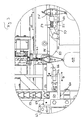
- FIG. 2 shows an end view of the transfer device 1 already described.
- the smoke plug or rod 4 which is detachably held in the transfer device in receiving means is again visible.
- a first end-side holding part 7 and a second end-side holding part can be provided ( Figure 1) wherein at least one of the holding parts, in Figure 1, the holding part 5, is driven, for example pneumatically driven, to effect releasable retention of the smoking plug.
- FIG. 2 shows a conveying means 52 which is driven by a chain 53 with a deflection 53 '(FIG. 3) by a drive (not shown in the drawing) which leads the individual bars 4 away from the transfer device and a multiplicity of loaded bars 4 for further processing of the held thereon Sausages ready.
- Another chain 53 is also provided on the other side of the device for the other end of the rods.
- the two chains are synchronized via a common drive shaft (not shown), which in the example shown is below the sausage hanging on the bar, but in the case of a chain guide of the chain 53 would lie vertically upwards instead of the chain guide shown above above the smoking bars.
- 51 is a magazine for the bars 4, from which an empty rod 4 or smoking can be brought back into the holding position in the transfer device 1.
- the transfer device is preferably equipped as a self-standing unit with a frame 6, by means of which it can be arranged at the end of the safety gear 3.
- the arranged on the transfer device rod changing device is designated 60 and has, for example for the two ends of the rod 4 and in both shots 5,7 for the rod depending on a carriage 61 which perform a translational back and forth movement in the direction of arrow D. can.
- a carriage 61 which perform a translational back and forth movement in the direction of arrow D. can.
- the carriage at the front end of the rod or in the region of the receptacle 5 is shown, which itself is not shown in the figure, so that the view of the free end of the rod 4 can be seen, the would be held in the recording 5.
- a fixed part 62 of the rod changing device contains the linear drive for the carriage, which can be formed individually for example by a pneumatic piston-cylinder arrangement for both carriages or for each carriage individually. Other drive variants are possible and familiar to those skilled in the execution of a reciprocating carriage movement.
- the drive of a first slide member 64 which is connected via a further slide member 67 with the Wegkitteil 66 of the carriage in conjunction.
- the part 64 forms a receptacle 65 for the next to be placed in loading position bar 4 'from.
- the Weggarteil 66 of the carriage extends to the rod 4, which is located in the receiving means 5, 7 of the transfer device and thus in loading position.
- the removal part 66 can also partially engage under the rod in order to support it while it is being guided away.
- the rod 4 is loaded by the transfer device with the packaging units, in particular sausages, which is illustrated in FIGS. 2 and 3 with the sausage 100 and will be explained in more detail below.
- the conveyor is gradually filled along its entire horizontal extent with loaded rods.
- Preferred is the explained procedure, in which the receiving pocket is stationary and waiting for the rod 4. Below is then each driven the chain 53 and brought the next pocket 54 in the waiting position. But it could also be done so that the respectively to be loaded with the rod pocket by the drive of the chain 53 is brought into loading position exactly when the rod is delivered by the carriage, which, however, a finer synchronization between the carriage and the drive of the chain 53 needed.
- the slide member 66 is lowered according to arrow E along the guides 68, so that the carriage under the bar now located in Beladepositon 4 'can go back to the starting position, in which the slide member again in the illustrated harnesse position is moved.
- the downward and upward movement of the slide member 66 along the guides 68 is e.g. also effected pneumatically or by means of electromagnets, which will not be explained further here, since it is readily apparent to the person skilled in the art how he can effect a corresponding movement.
- the carriage 61 is thus again in the position shown (initial position) and the rod 4 'is now in the loading position and is loaded.
- the recording 65 on the carriage for the next staff is still empty.
- the driven eg pneumatically or electromagnetically moves away, for example, pulled away , can be, so that the rod 4 'in the recording 65 falls.
- a retaining means 59 for the second lowermost rod 4" of the magazine is provided, for example in the form of in the rod 4 "both ends retractable bolt 59.
- the magazine 51 can preferably also be bent in the opposite direction, that is to say it has a curved configuration on the conveying means 52, which results in a more compact arrangement of the rod changing device and a Fillability of the magazine from the side of the conveyor 52 forth ago.
- the bar changing device is basically in the embodiment with slide in all types of transfer devices that hold the rod end, applicable.
- the detection means of the transfer device 1 for gripping the straps on the second rod-shaped element or the sword 30 are designed as hooks 10-23 which are attached to a revolving conveyor, which in the example shown is a chain 8, the at one end of the transfer device, which is the catcher 3 adjacent to a sprocket 9 is deflected.
- the chain also runs around a sprocket, which is driven by a controllable drive 25.
- the controller 50 shown only schematically, is correspondingly connected to the drive 25 by control lines. This drive is eg an electric motor drive with a servomotor.
- the gripping means 10-23 run with the chain 8 in the direction of arrow A and are deflected in the region of the end of the safety gear 3.
- the gripping of the holding loops of the packaging units takes place in such a way that the hook-shaped gripping means dip into a top-side groove 31 of the sword 30 after the diversion, via which groove the holding loop tensions.
- FIG. 4 shows a plan view of a part of the blade 30 with the groove 31 as well as holding straps 96 and 95 which span the groove 31.
- the straps can be promoted on the sword, this is kept flying by means of several pairs of retaining bolts, which are each withdrawn when passing a strap from the sword, in which time the holding of the sword is taken over by other pairs of retaining bolts.
- This is known in principle.
- FIG. 4 only the retaining bolt pairs 34, 35 and 36, 37 are shown as an example.
- the example shown with the continuously rotating conveyor with the gripping means arranged thereon is to be understood as a preferred example.
- FIG. 5 shows a detailed view of the gripping means, which are designed as hooks and their release by a triggering means for releasing the respective retaining loop.
- the chain 8 is again visible, on which the gripping means 18, 19 and 20 are fixedly arranged by fastening means 40.
- the single gripping means is designed in this preferred example as a hook, which has a pivotable hook part, which is movable from its gripping position for gripping the straps in a release position.
- the single hook has in this example a fixed hook portion 43 which is attached to the tab 40. Fixed is also the support member 44 for a spring means 45, in the example shown a compression spring.
- a pivotable hook portion 46 with the hook end 47 is pivotally mounted about an axis 41 on the fixed hook portion 43.
- a release part 42 is further arranged.
- This can be, for example, a fixed element or a rotatable roller.
- the gripping means 18 and 19 are shown in Figure 5 in the gripping position. In this position, they are previously immersed in the groove 32 of the sword 30 and have the respective retaining strap 93 and 92 of the sausage 103 and 102, respectively, on which the groove 30 spanning holding strap part used.
- the sausages 102 and 103 thus depend on the gripping means 18 and 19 while at the same time the smoke sticks 4 passes through the retaining loop.
- the sausages are conveyed in the direction of arrow B.
- the release of a packaging unit is now shown.
- the movable, pivotable hook member 46 is pivoted against the force of the compression spring 45, so that the hook tip 47 retracts behind the fixed hook part and the retaining loop is stripped from the hook tip 47.
- This stripping solution is a preferred example.
- the hook could also be pivoted so far that the strap slipped by the inclination of the hook tip itself by this and thus reaches the smoke sticks 4.
- the pivoting of the movable hook member 46 is effected by a trigger means.
- This release means is in the example shown, a trip block 28 having a control cam 28 'through which the respective release member 42 can be acted upon to cause the pivotal movement of the movable hook member 46 about the pivot axis 41.
- the trip block 28 is guided for example in a rail 29 and is driven by a conveyor 27 in the direction of arrow C.
- the triggering means thus runs counter to the conveying means of the gripping means and thus meets on its way from the end facing away from the sword of the smoking plug to the sword end of the smoking plug gradually to all funded by the gripping means packaging units.
- the gripping means release the packaging units.
- a motor 26 (FIG. 1) can be provided, which drives the toothed belt 27.
- the motor 26 is also connected to the controller 50, which can thus determine at which position a single packaging unit is set down or released.
- the triggering means may be carried out differently than shown in the preferred example.
- a plurality of fixedly positioned release means could be provided, which are individually controllable to act on a release part of the gripping means.
- Such individual triggering means could be actuated eg electromagnetically or pneumatically. In this way, the release and positioning can be effected, in which case the position can not be selected continuously by moving the trip block, but is given by the arrangement of the individual release means.
- the controller 50 is also preferably designed for the control of the rod changing device 60 and for the control of the means 58 and 59 in the magazine.
- FIG. 1 an arrangement of transfer device 1 with rod changing device 60, safety gear 3 and a closing machine 2 for the sausage-shaped packages is formed, as shown in Figures 1 and 6.
- the closing device 2 is a known closing device, which sets closure clips on the sausage-shaped packaging units.
- the retaining loop is attached to the respective packaging unit.
- the catching device 3 with the sword 30 takes over the individual straps and thus the packaging units and transports them along the sword 30 in the manner described or in another manner. Thereafter, the transfer device 1 described in detail adjoins.
- a controller 50 is provided, e.g.
- control of the closing machine 2 is synchronized, which controls all drives of the closing device, the safety gear and the transfer device including rod changing device synchronized, but at least the drives of the safety gear and the transfer device. There may also be individual controls on the devices that are synchronized with each other.
Abstract
Description
Die Erfindung betrifft eine Stabwechseleinheit an einer Übergabevorrichtung gemäss Anspruch 1. Ferner betrifft die Erfindung eine Übergabevorrichtung mit einer solchen Stabwechseleinrichtung und weiter eine Anordnung aus einer solchen Übergabevorrichtung und einer Fangvorrichtung für Verpackungseinheiten mit Halteschlaufen.The invention relates to a bar changing unit on a transfer device according to claim 1. Furthermore, the invention relates to a transfer device with such a rod changing device and further to an arrangement of such a transfer device and a safety device for packaging units with straps.
Es ist bekannt, Würste, an die beim Setzen des einen Verschlussclips eine Halteschlaufe befestigt worden ist, hängend an einem stabförmigen Element von der Verschliessmaschine (Clipmaschine) wegzufördern, so z.B. aus
Der Erfindung liegt die Aufgabe zu Grunde eine Stabwechseleinrichtung zu schaffen, welche den möglichst unterbruchslosen Betrieb einer Übergabevorrichtung ermöglicht, die die hängenden Verpackungseinheiten vom Schwert an einen Stab übergibt.The invention is based on the object to provide a rod changing device which allows the most uninterruptible operation of a transfer device that passes the hanging packaging units from the sword to a rod.
Diese Aufgabe wird mit den Merkmalen des Anspruchs 1 gelöst.This object is achieved with the features of claim 1.
Dadurch, dass die Einrichtung einen Stabwechselschlitten aufweist, durch den mit einer Schlittenbewegung aus einer Ausgangsstellung in die eine Schlittenrichtung sowohl ein beladener Stab aus den Aufnahmemitteln wegführbar als auch ein zweiter Stab in die Aufnahmemittel einführbar ist, worin er durch die Übergabevorrichtung beladbar ist, ergibt sich ein sehr rascher und einfacher Stabwechsel in der Übergabevorrichtung, die dadurch praktisch unterbruchslos betrieben werden kann. Die Einrichtung kann Stäbe von beliebigem Format bzw. Querschnitt wechseln und ist somit für Stäbe von verschiedenen Herstellern verwendbar.Characterized in that the device comprises a rod changing carriage, by the with a carriage movement from a starting position in the one carriage direction both a loaded rod from the receiving means wegführbar and a second rod is inserted into the receiving means, wherein it is loaded by the transfer device, results in a very quick and easy change of staff in the transfer device, which can be operated practically without interruption. The device can change rods of any format or cross section and is therefore suitable for rods from different manufacturers.
Vorzugsweise gibt der Schlitten den beladenen Stab an ein Fördermittel zur Aufnahme einer Mehrzahl beladener Stäbe weiter, so dass der Schlitten sofort nach der Abgabe des Stabes in seine Ausgangsstellung zurückfahren kann und die weitere Förderung der beladenen Stäbe nach der Weitergabe vom Schlitten unabhängig erfolgt. Das Fördermittel ist bevorzugt ein Kettenförderer oder Zahnriemenförderer mit einer Umlenkrolle, bei welcher die Kette oder der Riemen von einer im Wesentlichen vertikalen Richtung in eine im Wesentlichen horizontale Richtung übergeht, wobei ein vom Stabwechselschlitten weggeführter Stab vom Fördermittel übernehmbar und horizontal weiterförderbar ist. Dies ergibt eine kompakte Ausführung auch bei Bereitstellung einer grossen Anzahl beladener Stäbe. Bevorzugterweise führt der die Wegführbewegung der beladenen Stäbe ausführende Schlittenteil bei der Schlittenrückbewegung in die Ausgangsstellung eine Absenkbewegung durch, womit der Schlitten unter dem abgesetzten leeren Stab hindurch in die Ausgangsstellung zurückfahren kann, in welcher der Schlitten eine Aufwärtsbewegung ausführt. In der Ausgangstellung ist der Schlitten mit einem Stab aus dem Stabmagazin beladbar, indem vorzugsweise das Stabmagazin zur Aufnahme mehrerer vertikal über dem Schlitten zu liegen kommender Stäbe ausgestaltet ist, von denen der unterste Stab schwerkraftabhängig in den Schlitten gelangt. Dies ergibt eine einfache und rasche Beladung. Sie kann so ausgeführt sein, dass an der Einrichtung oder am Magazin eine steuerbare Rückhaltung für den untersten Stab im Magazin und eine synchron steuerbare weitere Rückhaltung für den zweituntersten Stab im Magazin vorgesehen ist. Somit kann der unterste Stab in den Schlitten fallen, während der zweitunterste Stab zurückgehalten wird. Dieser kann dann nach der Beladung des Schlittens die unterste Position im Magazin einnehmen.Preferably, the carriage forwards the loaded bar to a conveyor for receiving a plurality of loaded bars, so that the carriage can return immediately after the dispensing of the rod to its initial position and the further promotion of the loaded rods after the transfer from the carriage is independent. The conveying means is preferably a chain conveyor or toothed belt conveyor with a deflection roller, in which the chain or belt passes from a substantially vertical direction into a substantially horizontal direction, whereby a rod led away from the rod changing carriage can be taken over by the conveying means and conveyed further horizontally. This results in a compact design even with the provision of a large number of loaded rods. Preferably, the slide member carrying out the removal movement of the loaded rods performs a lowering movement during the carriage return movement into the initial position, with which the carriage can move back under the stepped empty rod into the starting position in which the carriage carries out an upward movement. In the initial position of the carriage with a rod from the rod magazine can be loaded by preferably the rod magazine for receiving a plurality of vertically above the carriage coming to be formed rods, of which the bottom rod passes gravity dependent in the carriage. This results in a simple and quick loading. It can be designed so that on the device or on the magazine a controllable retention for the lowest bar in the magazine and a synchronously controllable further retention for the second lowest bar in the magazine is provided. Thus, the bottom bar may fall into the carriage while the second bottom bar is restrained. This can then occupy the lowest position in the magazine after loading the carriage.
Der Erfindung liegt weiter die Aufgabe zu Grunde eine Übernahmevorrichtung mit einfachem und raschem Wechsel der beladenen Stäbe zu schaffen. Dies wird mit einer Übernahmevorrichtung erzielt, die mit der erfindungsgemässen Stabwechseleinrichtung ausgerüstet ist.The invention is further based on the object to provide a transfer device with a simple and rapid change of the loaded rods. This is achieved with a transfer device which is equipped with the inventive rod changing device.
Bevorzugterweise ist die Übernahmevorrichtung so ausgestaltet, dass ein Auslösemittel steuerbar an wählbaren Positionen ein Loslassen der Verpackungseinheiten bzw. Würste durch die Erfassungsmittel bewirkt; damit kann ein definiertes Absetzen der Verpackungseinheiten auf dem zweiten Element erfolgen. Dies lässt sich somit nach Wunsch und optimal beladen. Insbesondere lässt sich der Abstand der Verpackungseinheiten voneinander auf dem zweiten Element auf einfache Weise bestimmen. Bevorzugt sind die Erfassungsmittel als Greifmittel und insbesondere als an einem umlaufenden Fördermittel, wie einer Kette oder einem Zahnriemen, angeordnete Haken vorgesehen. Damit können die Verpackungseinheiten einzeln gegriffen und über die Rauchstange bzw. das zweite Element gefördert werden. Dort wirkt dann das steuerbare, positionierbare Auslösemittel zum Lösen des Griffes der Greifmittel. Dies erfolgt vorzugsweise, indem die Haken schwenkbar sind, was durch das Auslösemittel bewirkt wird. Durch die Schwenkbewegung der Haken gleiten die Halteschlaufen von diesen ab oder werden abgestreift und die Verpackungseinheit wird an der vom Auslösemittel bestimmten Position abgesetzt. Das Auslösemittel ist vorzugsweise ein Auslöseblock, der entgegen der Förderrichtung verfahrbar ist und so auf durch die Steuerung bestimmte Weise auf die Haken zu deren Auslösung zum Loslassen trifft. Dies ermöglicht eine praktisch stufenlose Positionierung der Verpackungseinheiten entlang des zweiten Elementes.Preferably, the transfer device is configured such that a triggering means controllably causes the packaging units or sausages to be released by the detecting means at selectable positions; This can be done a defined settling of the packaging units on the second element. This can thus be loaded as desired and optimally. In particular, the distance of the packaging units from one another on the second element can be determined in a simple manner. The detection means are preferably provided as gripping means and in particular as hooks arranged on a revolving conveyor, such as a chain or a toothed belt. Thus, the packaging units can be gripped individually and promoted on the smoking rod or the second element. There then acts the controllable, positionable release means for releasing the handle of the gripping means. This is preferably done by the hooks are pivotal, which is caused by the triggering means. As a result of the pivoting movement of the hooks, the holding loops slide off the latter or are stripped off and the packaging unit is set down at the position determined by the triggering means. The triggering means is preferably a trigger block, which is movable in the opposite direction to the conveying direction and thus, in a manner determined by the control, encounters the hooks for triggering them to release. this makes possible a virtually continuous positioning of the packaging units along the second element.
Die Anordnung aus der Übergabevorrichtung mit Stabwechseleinrichtung gemäss der Erfindung und der die Verpackungseinheiten bzw. Würste am Ausgang der Verschliessvorrichtung fangenden Fangvorrichtung ergibt ein einfaches automatisiertes Aufbringen der Verpackungseinheiten auf Rauchstecken und deren Bereitstellung für die Weiterverarbeitung der Würste.The arrangement of the transfer device with rod changing device according to the invention and the catching devices catching the packing units or sausages at the outlet of the closing device results in a simple automated application of the packaging units to smoking sticks and their provision for the further processing of the sausages.
Im folgenden werden Ausführungsbeispiele der Erfindung anhand der Figuren näher erläutert. Dabei zeigt
- Figur 1 eine Seitenansicht einer Übergabevorrichtung gemäss einem Ausführungsbeispiel der Erfindung;
Figur 2 eine Frontalansicht der Übergabevorrichtung von Figur 1;Figur 3 eine Detailansicht der Übergabevorrichtung vonFigur 2 mit dem Schlitten;Figur 4 eine Ansicht von oben auf ein erstes stabförmiges Element (Schwert), von welchem die hängenden Verpackungseinheiten mittels der Übergabevorrichtung abgegriffen werden;Figur 5 eine Detailansicht der Greifmittel und des Auslösemittels; undFigur 6 eine Seitenansicht einer Verschliessvorrichtung und eines Teils der Fangvorrichtung einer Anordnung aus diesen Vorrichtungen und einer Übergabevorrichtung.
- Figure 1 is a side view of a transfer device according to an embodiment of the invention;
- Figure 2 is a frontal view of the transfer device of Figure 1;
- Figure 3 is a detail view of the transfer device of Figure 2 with the carriage;
- Figure 4 is a top view of a first rod-shaped element (sword), from which the hanging packaging units are tapped by means of the transfer device;
- Figure 5 is a detail view of the gripping means and the triggering means; and
- Figure 6 is a side view of a closing device and a part of the safety gear of an arrangement of these devices and a transfer device.
Figur 1 zeigt eine Übergabevorrichtung 1 in Seitenansicht. Dieser werden an Halteschlaufen hängende Verpackungseinheiten von einer Fangvorrichtung 3 her zugeführt, welche diese Verpackungseinheiten von einer Verschliessvorrichtung übernommen hat, welche in Figur 6 dargestellt ist und noch erläutert wird. Die Fangvorrichtung 3 fördert die Verpackungseinheiten, welche in dem gezeigten Beispiel Würste sind, welche aber auch andere Gegenstände sein können, entlang eines zweiten stabförmigen Elementes 30, das auch als Schwert bezeichnet wird, und welches ebenfalls in Figur 6 in Seitenansicht ersichtlich ist sowie in Figur 4 in Draufsicht. Die Übergabevorrichtung 1 erfasst, und insbesondere greift, die Verpackungseinheiten im Endbereich des Schwertes, in welchem dieses an die Übergabevorrichtung 1 anschliesst. Die Übergabevorrichtung 1 ist zur lösbaren Halterung eines ersten stabförmigen Elementes bzw. Stabes 4, welches in der Regel ein Rauchstecken ist, wenn es sich bei den Verpackungseinheiten um Würste handelt, ausgestaltet. Die Übergabevorrichtung übergibt die am Schwert 30 hängenden Verpackungseinheiten an den Stab 4. Dieser wird in der Übergabevorrichtung 1 so gehalten, dass er im wesentlichen koaxial mit dem Schwert 30 der Fangvorrichtung angeordnet und gehalten werden kann.FIG. 1 shows a transfer device 1 in side view. These are supplied to holding straps hanging packaging units of a
Figur 2 zeigt eine stirnseitige Ansicht der bereits beschriebenen Übergabevorrichtung 1. Ersichtlich ist wiederum der Rauchstecken bzw. Stab 4, der in der Übergabevorrichtung in Aufnahmemitteln lösbar gehalten ist. Zu dieser Aufnahme bzw. Halterung des Stabes 4 in der Stellung, in der er mit den Verpackungseinheiten beladen wird, kann ein erstes stirnseitiges Halteteil 7 und ein zweites stirnseitiges Halteteil vorgesehen sein (Figur 1) wobei mindestens eines der Halteteile, in Figur 1 das Halteteil 5, angetrieben ist, z.B. pneumatisch angetrieben ist, um eine lösbare Halterung des Rauchsteckens zu bewirken. Sobald ein Rauchstecken 4 beladen ist, so wird er weggeführt und durch einen leeren Rauchstecken ersetzt, was nachfolgend anhand Figur 3 näher beschrieben wird. Der neu in die Beladestellung gebrachte Stab 4 wird dann wiederum durch die Übergabevorrichtung 1 mit Würsten beladen. In Figur 2 ist ein Fördermittel 52 dargestellt, welches über eine Kette 53 mit einer Umlenkung 53' (Figur 3) von einem nicht auf der Zeichnung ersichtlichen Antrieb angetrieben ist, die die einzelnen Stäbe 4 von der Übergabevorrichtung wegführt und eine Vielzahl von beladenen Stäben 4 zur Weiterverarbeitung der daran gehaltenen Würste bereitstellt. Eine weitere Kette 53 ist auch auf der anderen Seite der Einrichtung für die anderen Ende der Stäbe vorgesehen. Die beiden Ketten werden über eine (nicht gezeigte) gemeinsame Antriebswelle synchronisiert, die im gezeigten Beispiel unterhalb der am Stab hängenden Würste liegt, aber im Falle einer Kettenführung der Kette 53 vertikal nach oben anstelle der gezeigten Kettenführung nach unten oberhalb der Rauchstäbe liegen würde. Mit 51 ist ein Magazin für die Stäbe 4 bezeichnet, aus welchem ein leerer Stab 4 bzw. Rauchstecken wieder in die Haltestellung in der Übergabevorrichtung 1 gebracht werden kann. Die Übergabevorrichtung ist vorzugsweise als selbststehende Einheit mit einem Gestell 6 ausgerüstet, mittels welchem sie am Ende der Fangvorrichtung 3 angeordnet werden kann.FIG. 2 shows an end view of the transfer device 1 already described. The smoke plug or
Die an der Übergabevorrichtung angeordnete Stabwechseleinrichtung ist mit 60 bezeichnet und weist z.B. für die beiden Enden des Stabes 4 bzw. bei beiden Aufnahmen 5,7 für den Stab je einen Schlitten 61 auf, der eine translatorische Hin- und Herbewegung in Richtung des Pfeiles D ausführen kann. Natürlich könnte entlang des Stabes, z.B. in dessen Mitte, ein weiterer Schlitten angeordnet sein. In der Figur ist gemäss der Art der Frontalansicht nur der Schlitten am vorderen Ende des Stabes bzw. im Bereich der Aufnahme 5 dargestellt, welche selber in der Figur nicht dargestellt ist, so dass der Blick auf das freie Ende des Stabes 4 ersichtlich ist, der in der Aufnahme 5 gehalten wäre. Die weitere Beschreibung erfolgt nur anhand des einen Schlittens der Stabwechseleinrichtung, doch ist der zweite Schlitten der Einrichtung am anderen Stabende entsprechend ausgeführt, bzw. wäre ein ggf. vorgesehener dritter oder gar vierter Schlitten entsprechend ausgeführt. Ein feststehender Teil 62 der Stabwechseleinrichtung enthält den Linearantrieb für die Schlitten, der z.B. von einer pneumatischen Kolben- Zylinderanordnung gemeinsam für beide Schlitten oder jeweils für jeden Schlitten einzeln gebildet sein kann. Auch andere Antriebsvarianten sind möglich und dem Fachmann zur Ausführung einer hin- und herlaufenden Schlittenbewegung geläufig. Über das Glied 63 erfolgt der Antrieb eines ersten Schlittenteiles 64, das über einen weiteren Schlittenteil 67 mit dem Wegführteil 66 des Schlittens in Verbindung ist. Der Teil 64 bildet eine Aufnahme 65 für den nächsten in Beladestellung zu bringenden Stab 4' aus. Das Wegführteil 66 des Schlittens reicht bis zum Stab 4, der sich in den Aufnahmemitteln 5, 7 der Übergabevorrichtung und somit in Beladestellung befindet. Das Wegführteil 66 kann den Stab auch teilweise untergreifen, um ihn beim Wegführen abzustützen. In der dargestellten Beladestellung für den Stab wird der Stab 4 von der Übergabevorrichtung mit den Verpackungseinheiten, insbesondere Würsten, beladen, was in den Figuren 2 und 3 mit der Wurst 100 dargestellt ist und nachfolgend noch genauer erläutert wird.The arranged on the transfer device rod changing device is designated 60 and has, for example for the two ends of the
Ist der Stab 4 vollständig beladen, so wird der Schlitten 61 in Figur 3 nach rechts gefahren. Ebenso werden die Aufnahmemittel 5,7 für den Stab 4 gelöst, so dass dieser vom Schlitten 61, bzw. vom Schlittenteil 66 nach rechts weggeführt werden kann. Eine Führung 55 mit einer Gleitfläche 56 (natürlich jeweils wieder für beide Endbereiche des Stabes vorgesehen) lässt den Stab 4 gestossen vom Schlittenteil 66 über die Gleitfläche 56 zum Fördermittel 52 gelangen, wo der Stab 4 in diejenige der Aufnahmetaschen(Tasche 54) aufgenommen wird, die vorgängig nach oben bewegt worden ist und dort auf den Stab 4 wartet. Die vorgängig von dem Fördermittel nach oben bewegte Aufnahmetasche 54' ist bereits vom vorgängig beladenen und vom Schlitten weggeführten Stab besetzt, weitere Taschen, die aber in der Figur nicht dargestellt sind, sind mit weiteren vorgängigen Stäben besetzt. So wird das Fördermittel nach und nach entlang seiner ganzen horizontalen Ausdehnung mit beladenen Stäben gefüllt. Bevorzugt ist das erläuterte Vorgehen, bei dem die Aufnahmetasche stillsteht und auf den Stab 4 wartet. Nachfolgend wird dann jeweils die Kette 53 angetrieben und die nächste Tasche 54 in Wartestellung gebracht. Es könnte aber auch so vorgegangen werden, dass die jeweils mit dem Stab zu beladende Tasche vom Antrieb der Kette 53 genau dann in Beladeposition gebracht wird, wenn der Stab vom Schlitten angeliefert wird, was allerdings eine feinere Synchronisation zwischen dem Schlitten und dem Antrieb der Kette 53 benötigt.If the
Ist ein Stab 4 auf die beschriebene Weise von der Beladestellung weggeführt worden, so gelangt andererseits mit der gleichen Schlittenbewegung der nächste leere Stab 4' in der Aufnahme 65 des Schlittens in die Beladeposition der Übergabevorrichtung und kann dort von den Aufnahmemitteln 5,7 derselben fixiert werden. Für die Rückbewegung des Schlittens in der Figur nach links wird das Schlittenteil 66 gemäss Pfeil E entlang der Führungen 68 abgesenkt, damit der Schlitten unter dem nun in Beladepositon befindlichen Stab 4' zurück in die Ausgangsstellung fahren kann, in der der Schlittenteil wieder in die dargestellte hochgefahrene Stellung bewegt wird. Die Bewegung nach unten und nach oben des Schlittenteils 66 entlang den Führungen 68 wird z.B. ebenfalls pneumatisch oder mittels Elektromagneten bewirkt, was hier nicht weiter erläutert wird, da dem Fachmann ohne Weiteres ersichtlich ist, wie er eine entsprechende Bewegung bewirken kann.If a
Der Schlitten 61 ist somit wieder in der dargestellten Position (Ausgangsstellung) und der Stab 4' ist nun in der Beladeposition und wird beladen. Die Aufnahme 65 am Schlitten für den nächsten Stab ist aber noch leer. Bevorzugt erfolgt die Einbringung des nächsten Stabes in die Aufnahme 65 durch ein schwerkraftbewirktes Fallenlassen des nächsten Stabes 4" aus dem Magazin 51. Dazu ist dieses oder ist die Stabwechseleinrichtung 60 mit Halteteilen 58 versehen, die angetrieben (z.B. pneumatisch oder elektromagnetisch) wegbewegt, z.b. weggezogen, werden können, so dass der Stab 4' in die Aufnahme 65 fällt. Damit nur der Stab 4' fällt und nicht auch der Stab 4" und die weiteren Stäbe im Magazin, ist ein Rückhaltemittel 59 für den zweituntersten Stab 4" des Magazins vorgesehen, z.B. in Form von in den Stab 4" beiderends einfahrbaren Bolzen 59. Damit wird der Stab 4" gehalten, wenn die Halteteile 58 offen sind und der Stab 4' in die Aufnahme fällt. Sobald die Halteteile 58 wieder geschlossen sind und die Aufnahme 65 zum Magazin 51 hin schliessen, werden die Bolzen 59 wieder zurückgezogen, so dass der Stab 4" sich nach unten bewegt, bis er auf den Haltemitteln 58 aufliegt und damit den untersten Stab des Magazins bildet. Der Vorgang wiederholt sich dann von der gezeigten Augangsstellung aus mit erneutem Wegführen des beladenen Stabes, dessen Aufnahme auf das Fördermittel 52, dem Halten des nächsten leeren Stabes in der Beladeposition und dem Zurückfahren des Schlittens und dessen Befüllung in der Aufnahme 65 mit dem untersten Stab aus dem Magazin. Es ergibt sich ein rascher Stabwechsel, bei dem die Beladung von Stäben nur kurzzeitig unterbrochen wird. Das Magazin 51 kann bevorzugt auch in Gegenrichtung gebogen, also auf das Fördermittel 52 hin gebogen ausgeführt sein, was eine kompaktere Anordnung der Stabwechseleinrichtung und eine Befüllbarkeit des Magazins von der Seite der Fördereinrichtung 52 her ergibt.The
Nachfolgend wird eine bevorzugte Ausführungsform der Übergabevorrichtung geschildert. Die Stabwechseleinrichtung ist aber grundsätzlich in der Ausführung mit Schlitten bei allen Arten von Übergabevorrichtungen, die den Stab endseitig halten, anwendbar.Hereinafter, a preferred embodiment of the transfer device will be described. However, the bar changing device is basically in the embodiment with slide in all types of transfer devices that hold the rod end, applicable.
Im dargestellten Beispiel von Figur 1 sind die Erfassungsmittel der Übergabevorrichtung 1 zum Greifen der Halteschlaufen am zweiten stabförmigen Element bzw. am Schwert 30 als Haken 10-23 ausgeführt, welche an einem umlaufenden Fördermittel befestigt sind, welches im gezeigten Beispiel eine Kette 8 ist, die am einen Ende der Übergabevorrichtung, welches der Fangvorrichtung 3 benachbart ist um ein Kettenrad 9 umgelenkt wird. Am anderen Ende der Übergabevorrichtung läuft die Kette ebenfalls um ein Kettenrad, welches von einem steuerbaren Antrieb 25 angetrieben wird. Die nur schematisch dargestellte Steuerung 50 ist entsprechend mit Steuerleitungen mit dem Antrieb 25 verbunden. Dieser Antrieb ist z.B. ein elektromotorischer Antrieb mit einem Servomotor. Die Greifmittel 10-23 laufen mit der Kette 8 in Richtung des Pfeiles A und werden im Bereich des Endes der Fangvorrichtung 3 umgelenkt. Bei der gezeigten Ausführungsform erfolgt das Greifen der Halteschlaufen der Verpackungseinheiten derart, dass die hakenförmigen Greifmittel nach der Umlenkung in eine oberseitige Nut 31 des Schwertes 30 eintauchen, über welche Nut sich die Halteschlaufe spannt.In the illustrated example of Figure 1, the detection means of the transfer device 1 for gripping the straps on the second rod-shaped element or the
In Figur 4 ist eine Draufsicht auf einen Teil des Schwertes 30 mit der Nut 31 sowie mit Halteschlaufen 96 und 95 gezeigt, welche die Nut 31 überspannen. Mit dem Eintauchen eines der hakenförmigen Greifmittel in die Nut 31 und einer schnelleren Bewegung des Greifmittels als es der Fördergeschwindigkeit der Halteschlaufen bzw. Verpackungseinheiten entlang des Schwertes entspricht, kann somit jeweils eine Halteschlaufe von dem Haken gegriffen und dadurch durch das Greifmittel übernommen werden. Figur 4 zeigt die Förderung der Halteschlaufen 95 und 96 am Schwert mittels Förderlaschen 33, 33' welche in seitliche Nuten des Schwertes 30 eingreifen und damit jeweils die Halteschlaufe mit der Geschwindigkeit der Ketten 32 und 32' fördern, an welchen die Förderlaschen 33 bzw. 33' befestigt sind. Damit die Halteschlaufen über das Schwert gefördert werden können, ist dieses fliegend mittels mehreren Paaren von Haltebolzen gehalten, welche jeweils beim Passieren einer Halteschlaufe vom Schwert zurückgezogen werden, wobei in dieser Zeit das Halten des Schwertes durch andere Haltebolzenpaare übernommen wird. Dies ist.grundsätzlich bekannt. In der Figur 4 sind dazu als Beispiel lediglich die Haltebolzenpaare 34, 35 sowie 36, 37 dargestellt. Sobald ein hakenförmiges Greifmittel die Halteschlaufe gegriffen hat, wird sie durch das etwas schneller als die Ketten 32, 32' der Fangvorrichtung 3 laufende Greifmittel bis zum Ende des Schwertes weitergefördert und ab dort nur noch am Haken hängend weitergefördert. In Figur 1 ist ersichtlich, wie am Ende der Fangvorrichtung 3 einzelne Würste 107, 106 und 105 in Pfeilrichtung B gefördert werden, wobei die Wurst 107 mit ihrer Halteschlaufe 96 am Schwert hängt und noch durch die Förderlaschen 33, 33' gefördert wird. Die Wurst 106 mit ihrer in der Figur nicht ersichtlichen Halteschlaufe wird nächstens durch das bereits umgelenkte Greifmittel 16 ergriffen und entsprechend durch dieses bis zum Ende des Schwertes gefördert. Die Ketten 32, 32' der Fangvorrichtung sind vorher umgelenkt worden und haben die Förderung entlang des Schwertes 30 an dieser Stelle schon beendet. Ganz am Ende des Schwertes befindlich ist ein vorher umgelenktes Greifmittel 17, an welchem die nur teilweise ersichtliche Wurst 104 hängt. Die Greifmittel 18, 19 und 20, an welchen jeweils die Würste 103, 102 und 101 mittels der Halteschlaufen 93, 92 und 91 gehalten sind fördern diese in Richtung des Pfeiles B über den Rauchstecken 4. Da der Rauchstecken im westentlichen koaxial mit dem Schwert angeordnet ist, umfassen die Halteschlaufen, welche vorgängig das Schwert umfasst haben, nun den Rauchstecken 4. Die vorderste Verpackungseinheit 100 mit der Halteschlaufe 90 ist bereits vom Greifmittel 21 losgelassen worden, so dass die Verpackungseinheit nun hängend am Rauchstecken und von diesem gehalten angeordnet und positioniert ist. Das gezeigte Beispiel mit dem kontinuierlich umlaufenden Fördermittel mit den daran angeordneten Greifmitteln ist als bevorzugtes Beispiel zu verstehen. Es können auch anders ausgestaltete und bewegte Erfassungsmittel vorgesehen sein, z.B. solche, welche bis zum Ende des Schwertes durch die Fangvorrichtung geförderte Verpackungseinheiten beim Abfallen derselben vom Schwert in ihren Halteschlaufen auffangen, z.B. mit Haken oder Stiften, und diese wiederum durch gemeinsame synchrone Förderung oder auch durch einzelne, asynchrone Förderung entlang des Rauchsteckens fördern.FIG. 4 shows a plan view of a part of the
Figur 5 zeigt nun eine Detailansicht der Greifmittel, die als Haken ausgebildet sind und deren Auslösung durch ein Auslösemittel zum Loslassen der jeweiligen Halteschlaufe. In Figur 5 ist wieder die Kette 8 ersichtlich, an welcher die Greifmittel 18, 19 und 20 durch Befestigungsmittel 40 fest angeordnet sind. Das einzelne Greifmittel ist in diesem bevorzugten Beispiel als Haken ausgeführt, welcher ein schwenkbares Hakenteil aufweist, das aus seiner Greifstellung zum Greifen der Halteschlaufen in eine Loslassstellung bewegbar ist. Der einzelne Haken weist in diesem Beispiel ein feststehendes Hakenteil 43 auf, das an der Lasche 40 befestigt ist. Feststehend ist ebenfalls das Abstützteil 44 für ein Federmittel 45, im gezeigten Beispiel eine Druckfeder. Ein schwenkbares Hakenteil 46 mit dem Hakenende 47 ist um eine Achse 41 am feststehenden Hakenteil 43 schwenkbar befestigt. Am schwenkbaren Hakenteil 46 ist weiter ein Löseteil 42 angeordnet. Dies kann z.B. ein feststehendes Element oder eine drehbare Rolle sein. Die Greifmittel 18 und 19 sind in Figur 5 in Greifstellung gezeigt. In dieser Stellung sind sie vorgängig in die Nut 32 des Schwertes 30 eingetaucht und haben die jeweilige Halteschlaufe 93 bzw. 92 der Wurst 103 bzw. 102 an dem die Nut 30 überspannenden Halteschlaufenteil gegriffen. Die Würste 102 und 103 hängen somit an den Greifmitteln 18 und 19 während gleichzeitig der Rauchstecken 4 die Halteschlaufe durchsetzt. Durch das Fördermittel bzw. die Kette 8 werden die Würste in Richtung des Pfeiles B gefördert. Anhand des Greifmittels 20 wird nun das Loslassen einer Verpackungseinheit gezeigt. Dazu wird das bewegliche, schwenkbare Hakenteil 46 entgegen der Kraft der Druckfeder 45 geschwenkt, so dass die Hakenspitze 47 sich hinter das feststehende Hakenteil zurückzieht und die Halteschlaufe von der Hakenspitze 47 abgestreift wird. Diese Lösung mit der Abstreifung ist ein bevorzugtes Beispiel. Der Haken könnte auch soweit geschwenkt werden, dass die Halteschlaufe lediglich durch die Schrägstellung der Hakenspitze von selber von dieser abrutscht und somit auf den Rauchstecken 4 gelangt. Das Schwenken des beweglichen Hakenteils 46 wird durch ein Auslösemittel bewirkt. Dieses Auslösemittel ist im gezeigten Beispiel ein Auslöseblock 28 mit einer Steuerkurve 28', durch welche das jeweilige Löseteil 42 beaufschlagbar ist, um die Schwenkbewegung des beweglichen Hakenteils 46 um die Schwenkachse 41 bewirken. Der Auslöseblock 28 ist dabei z.B. in einer Schiene 29 geführt und wird durch ein Fördermittel 27 in Richtung des Pfeiles C angetrieben. Das Auslösemittel läuft somit dem Fördermittel der Greifmittel entgegengesetzt und trifft damit auf seinem Weg von der dem Schwert abgewandten Ende des Rauchsteckens zu dem schwertseitigen Ende des Rauchsteckens nach und nach auf alle durch die Greifmittel geförderten Verpackungseinheiten. Durch die Steuerung des angetrieben bewegten Auslösemittels kann somit bestimmt werden, an welcher Position entlang des Rauchsteckens die Greifmittel die Verpackungseinheiten loslassen. Zum gesteuerten Antrieb des Auslösemittels kann ein Motor 26 (Figur 1) vorgesehen sein, welcher den Zahnriemen 27 antreibt. Der Motor 26 ist ebenfalls mit der Steuerung 50 verbunden, welche somit bestimmen kann, an welcher Position eine einzelne Verpackungseinheit abgesetzt bzw. losgelassen wird. Auch das Auslösemittel kann natürlich anders ausgeführt werden, als in dem bevorzugten Beispiel gezeigt. So könnten eine Vielzahl von fest positionierten Auslösemitteln vorgesehen sein, welche einzeln ansteuerbar sind, um auf ein Löseteil der Greifmittel einzuwirken. Solche einzelnen Auslösemittel könnten z.B. elektromagnetisch oder pneumatisch betätigt werden. Auch auf diese Weise kann das Loslassen und Positionieren bewirkt werden, wobei in diesem Fall die Position nicht stufenlos durch Verfahren des Auslöseblockes gewählt werden kann, sondern fix durch die Anordnung der einzelnen Auslösemittel gegeben ist.Figure 5 shows a detailed view of the gripping means, which are designed as hooks and their release by a triggering means for releasing the respective retaining loop. In Figure 5, the
Die Steuerung 50 ist vorzugsweise ebenfalls für die Steuerung der Stabwechseleinrichtung 60 ausgebildet und für die Steuerung der Mittel 58 und 59 im Magazin.The
Auf die geschilderte Weise wird eine Anordnung aus Übergabevorrichtung 1 mit Stabwechseleinrichtung 60, Fangvorrichtung 3 sowie einer Verschliessmaschine 2 für die wurstförmigen Verpackungen gebildet, wie dies in den Figuren 1 und 6 dargestellt ist. Die Verschliessvorrichtung 2 ist dabei eine bekannte Verschliessvorrichtung, welche Verschlussclips an den wurstförmigen Verpackungseinheiten setzt. Dabei wird auch die Halteschlaufe an der jeweiligen Verpackungseinheit befestigt. Die Fangvorrichtung 3 mit dem Schwert 30 übernimmt die einzelnen Halteschlaufen und damit die Verpackungseinheiten und transportiert diese entlang des Schwertes 30 auf die beschriebene Weise oder auf eine andere Art. Danach schliesst sich die im Detail beschriebene Übergabevorrichtung 1 an. Vorzugsweise ist eine Steuerung 50 vorgesehen, die z.B. die Steuerung der Verschliessmaschine 2 ist, die alle Antriebe der Verschliessvorrichtung, der Fangvorrichtung und der Übergabevorrichtung inklusive Stabwechseleinrichtung synchronisiert steuert, wenigstens aber die Antriebe der Fangvorrichtung und der Übergabevorrichtung. Es können auch einzelne Steuerungen bei den Vorrichtungen vorhanden sein, die miteinander synchronisiert sind.In the manner described, an arrangement of transfer device 1 with
Claims (18)
Applications Claiming Priority (1)
| Application Number | Priority Date | Filing Date | Title |
|---|---|---|---|
| CH13362006 | 2006-08-22 |
Publications (2)
| Publication Number | Publication Date |
|---|---|
| EP1891858A1 true EP1891858A1 (en) | 2008-02-27 |
| EP1891858B1 EP1891858B1 (en) | 2013-12-25 |
Family
ID=38779773
Family Applications (1)
| Application Number | Title | Priority Date | Filing Date |
|---|---|---|---|
| EP20070015071 Active EP1891858B1 (en) | 2006-08-22 | 2007-08-01 | Bar changing device in a transfer device for hanging packaging units |
Country Status (2)
| Country | Link |
|---|---|
| EP (1) | EP1891858B1 (en) |
| ES (1) | ES2451215T3 (en) |
Cited By (8)
| Publication number | Priority date | Publication date | Assignee | Title |
|---|---|---|---|---|
| EP2305043A1 (en) * | 2009-10-02 | 2011-04-06 | Poly-clip System GmbH & Co. KG | Method and system for weighing products |
| EP2305042A1 (en) * | 2009-10-02 | 2011-04-06 | Poly-clip System GmbH & Co. KG | System for storing products |
| CH703003A1 (en) * | 2010-04-30 | 2011-10-31 | Tipper Tie Alpina Gmbh | Bar feeder on a suspension for sausage-shaped packaging. |
| WO2011134095A1 (en) | 2010-04-30 | 2011-11-03 | Tipper Tie Alpina Gmbh | Combination of closing and suspension device for sausage-type packagings |
| EP3072396A1 (en) | 2015-03-23 | 2016-09-28 | Poly-clip System GmbH & Co. KG | Handling system and method for sausage-shaped products |
| EP3103348A1 (en) | 2015-06-09 | 2016-12-14 | Poly-clip System GmbH & Co. KG | Handling apparatus and method |
| CN107050658A (en) * | 2017-04-17 | 2017-08-18 | 宁波中哲医疗科技有限公司 | A kind of automatic more exchange device of carbon-point |
| EP3732981A1 (en) * | 2019-04-29 | 2020-11-04 | Poly-clip System GmbH & Co. KG | Sausage loading method |
Citations (4)
| Publication number | Priority date | Publication date | Assignee | Title |
|---|---|---|---|---|
| JPS63219334A (en) * | 1987-03-09 | 1988-09-13 | ハイテツク株式会社 | Rod member supply apparatus for sausage suspension apparatus |
| DE3930876C1 (en) * | 1989-09-15 | 1990-07-26 | Guenter 6080 Gross-Gerau De Kollross | |
| US20030096568A1 (en) * | 2001-11-16 | 2003-05-22 | Minoru Kasai | Method and apparatus for suspending a sausage from a stick |
| DE10340632B3 (en) * | 2003-09-03 | 2004-12-30 | Poly-Clip System Gmbh & Co. Kg | Drive unit for conveyer system loading sausages onto smoking rod to hang by their loops, has mounting in rotary bearing to hold rod slanting as it turns. |
-
2007
- 2007-08-01 ES ES07015071T patent/ES2451215T3/en active Active
- 2007-08-01 EP EP20070015071 patent/EP1891858B1/en active Active
Patent Citations (4)
| Publication number | Priority date | Publication date | Assignee | Title |
|---|---|---|---|---|
| JPS63219334A (en) * | 1987-03-09 | 1988-09-13 | ハイテツク株式会社 | Rod member supply apparatus for sausage suspension apparatus |
| DE3930876C1 (en) * | 1989-09-15 | 1990-07-26 | Guenter 6080 Gross-Gerau De Kollross | |
| US20030096568A1 (en) * | 2001-11-16 | 2003-05-22 | Minoru Kasai | Method and apparatus for suspending a sausage from a stick |
| DE10340632B3 (en) * | 2003-09-03 | 2004-12-30 | Poly-Clip System Gmbh & Co. Kg | Drive unit for conveyer system loading sausages onto smoking rod to hang by their loops, has mounting in rotary bearing to hold rod slanting as it turns. |
Non-Patent Citations (1)
| Title |
|---|
| DATABASE WPI Week 198842, Derwent World Patents Index; AN 1988-297696 * |
Cited By (16)
| Publication number | Priority date | Publication date | Assignee | Title |
|---|---|---|---|---|
| EP2305043A1 (en) * | 2009-10-02 | 2011-04-06 | Poly-clip System GmbH & Co. KG | Method and system for weighing products |
| EP2305042A1 (en) * | 2009-10-02 | 2011-04-06 | Poly-clip System GmbH & Co. KG | System for storing products |
| US10051871B2 (en) | 2009-10-02 | 2018-08-21 | Poly-Clip System Gmbh & Co. Kg | System for transporting sausages |
| US8556687B2 (en) | 2009-10-02 | 2013-10-15 | Poly-Clip System Gmbh & Co. Kg | Method and system for weighing products |
| WO2011134095A1 (en) | 2010-04-30 | 2011-11-03 | Tipper Tie Alpina Gmbh | Combination of closing and suspension device for sausage-type packagings |
| CN102883616A (en) * | 2010-04-30 | 2013-01-16 | 体魄捆扎阿尔皮纳有限公司 | Stick feeding unit on a suspension device for sausage-type packagings |
| US8545293B2 (en) | 2010-04-30 | 2013-10-01 | Tipper Tie Alpina Gmbh | Stick feeding unit in a suspension device for sausage-type packaging units |
| WO2011134096A1 (en) | 2010-04-30 | 2011-11-03 | Tipper Tie Alpina Gmbh | Stick feeding unit on a suspension device for sausage-type packagings |
| US8790166B2 (en) | 2010-04-30 | 2014-07-29 | Tipper Tie Alpina Gmbh | Combination of closing and suspension device for sausage-type packaging units |
| CH703003A1 (en) * | 2010-04-30 | 2011-10-31 | Tipper Tie Alpina Gmbh | Bar feeder on a suspension for sausage-shaped packaging. |
| EP3072396A1 (en) | 2015-03-23 | 2016-09-28 | Poly-clip System GmbH & Co. KG | Handling system and method for sausage-shaped products |
| EP3103348A1 (en) | 2015-06-09 | 2016-12-14 | Poly-clip System GmbH & Co. KG | Handling apparatus and method |
| CN107050658A (en) * | 2017-04-17 | 2017-08-18 | 宁波中哲医疗科技有限公司 | A kind of automatic more exchange device of carbon-point |
| CN107050658B (en) * | 2017-04-17 | 2023-07-25 | 宁波中哲医疗科技有限公司 | Automatic replacement equipment for carbon rod |
| EP3732981A1 (en) * | 2019-04-29 | 2020-11-04 | Poly-clip System GmbH & Co. KG | Sausage loading method |
| US11116228B2 (en) | 2019-04-29 | 2021-09-14 | Poly-Clip System Gmbh & Co. Kg | Loading method |
Also Published As
| Publication number | Publication date |
|---|---|
| ES2451215T3 (en) | 2014-03-26 |
| EP1891858B1 (en) | 2013-12-25 |
Similar Documents
| Publication | Publication Date | Title |
|---|---|---|
| EP1891859B1 (en) | Transfer device for packaging units hanging from loops | |
| EP1891858B1 (en) | Bar changing device in a transfer device for hanging packaging units | |
| EP3250486B1 (en) | Method for filling the pockets of a transport device in the form of a suspension conveyor and device for carrying out said method | |
| DE1610467C3 (en) | Method and device for placing the slider and the upper end links on pre-assembled coupled zip fasteners | |
| EP0129864B1 (en) | Method and device for transferring individual sausages from an automatic stuffing machine to smoking or boiling pins | |
| EP2537651B1 (en) | Method and device for cutting a length of food into slices | |
| EP1985183B1 (en) | Smoking stick feed and method for exact feed positioning of a smoking stick | |
| DE102006017017A1 (en) | Direct connection of sausage clip and sausage conveyor | |
| EP1985185B1 (en) | Bar cartridge device in a transfer device for hanging packaging units | |
| EP2563152B1 (en) | Rod feeding device in a suspension device for sausage-shaped packages | |
| CH454010A (en) | Device for placing pieces of confectionery aligned on a feed device into packaging | |
| EP2008522A1 (en) | Method and device for picking up portions with a lug | |
| DE102006054039A1 (en) | Article i.e. sausage, receiving and transferring device, has circular chain running outside of straps and driven by engine, and strap attachments arranged at chain and pulled over rods, where attachments receive straps from guide | |
| EP2563151B1 (en) | Combination of closing and suspension device for sausage-type packagings | |
| DE2016054C3 (en) | Device for transferring containers into the conveyor of a preserving device | |
| DE2727924C2 (en) | Device for transferring a predetermined number of cylindrical objects, in particular cigarette tubes with filter tips, to packaging | |
| DE3300012C1 (en) | Program-controlled hanging device for portioned strings of sausages | |
| CH687714A5 (en) | Device for handling Stripes for Kettfadeneinziehmaschinen. | |
| DE2200311C2 (en) | Device for transporting and storing | |
| DE2001932C3 (en) | Device for transporting strand material | |
| AT394324B (en) | METHOD AND SYSTEM FOR DESCALING STAINLESS STEEL RODS | |
| DE10046417C1 (en) | Equipment laying hanging sausages horizontally and removing their suspension thread loops, employs traveling carriage feeder and system of inclined planes | |
| AT227168B (en) | Device for inserting bottles or the like in transport containers and for emptying the latter | |
| EP2380831B1 (en) | Device for transporting and separating smoking rods | |
| EP2277383B1 (en) | Device and method for hanging sausages |
Legal Events
| Date | Code | Title | Description |
|---|---|---|---|
| PUAI | Public reference made under article 153(3) epc to a published international application that has entered the european phase |
Free format text: ORIGINAL CODE: 0009012 |
|
| AK | Designated contracting states |
Kind code of ref document: A1 Designated state(s): AT BE BG CH CY CZ DE DK EE ES FI FR GB GR HU IE IS IT LI LT LU LV MC MT NL PL PT RO SE SI SK TR |
|
| AX | Request for extension of the european patent |
Extension state: AL BA HR MK YU |
|
| 17P | Request for examination filed |
Effective date: 20080826 |
|
| 17Q | First examination report despatched |
Effective date: 20080929 |
|
| AKX | Designation fees paid |
Designated state(s): DE FR IT |
|
| RBV | Designated contracting states (corrected) |
Designated state(s): AT BE BG CH CY CZ DE DK EE ES FI FR GB GR HU IE IS IT LI LT LU LV MC MT NL PL PT RO SE SI SK TR |
|
| GRAP | Despatch of communication of intention to grant a patent |
Free format text: ORIGINAL CODE: EPIDOSNIGR1 |
|
| GRAS | Grant fee paid |
Free format text: ORIGINAL CODE: EPIDOSNIGR3 |
|
| RAP1 | Party data changed (applicant data changed or rights of an application transferred) |
Owner name: TIPPER TIE ALPINA GMBH |
|
| GRAA | (expected) grant |
Free format text: ORIGINAL CODE: 0009210 |
|
| AK | Designated contracting states |
Kind code of ref document: B1 Designated state(s): AT BE BG CH CY CZ DE DK EE ES FI FR GB GR HU IE IS IT LI LT LU LV MC MT NL PL PT RO SE SI SK TR |
|
| REG | Reference to a national code |
Ref country code: GB Ref legal event code: FG4D Free format text: NOT ENGLISH |
|
| REG | Reference to a national code |
Ref country code: CH Ref legal event code: EP |
|
| REG | Reference to a national code |
Ref country code: AT Ref legal event code: REF Ref document number: 646090 Country of ref document: AT Kind code of ref document: T Effective date: 20140115 |
|
| REG | Reference to a national code |
Ref country code: IE Ref legal event code: FG4D Free format text: LANGUAGE OF EP DOCUMENT: GERMAN |
|
| REG | Reference to a national code |
Ref country code: DE Ref legal event code: R096 Ref document number: 502007012621 Country of ref document: DE Effective date: 20140213 |
|
| REG | Reference to a national code |
Ref country code: ES Ref legal event code: FG2A Ref document number: 2451215 Country of ref document: ES Kind code of ref document: T3 Effective date: 20140326 |
|
| PG25 | Lapsed in a contracting state [announced via postgrant information from national office to epo] |
Ref country code: LT Free format text: LAPSE BECAUSE OF FAILURE TO SUBMIT A TRANSLATION OF THE DESCRIPTION OR TO PAY THE FEE WITHIN THE PRESCRIBED TIME-LIMIT Effective date: 20131225 Ref country code: SE Free format text: LAPSE BECAUSE OF FAILURE TO SUBMIT A TRANSLATION OF THE DESCRIPTION OR TO PAY THE FEE WITHIN THE PRESCRIBED TIME-LIMIT Effective date: 20131225 Ref country code: FI Free format text: LAPSE BECAUSE OF FAILURE TO SUBMIT A TRANSLATION OF THE DESCRIPTION OR TO PAY THE FEE WITHIN THE PRESCRIBED TIME-LIMIT Effective date: 20131225 |
|
| REG | Reference to a national code |
Ref country code: NL Ref legal event code: VDEP Effective date: 20131225 |
|
| REG | Reference to a national code |
Ref country code: LT Ref legal event code: MG4D |
|
| PG25 | Lapsed in a contracting state [announced via postgrant information from national office to epo] |
Ref country code: LV Free format text: LAPSE BECAUSE OF FAILURE TO SUBMIT A TRANSLATION OF THE DESCRIPTION OR TO PAY THE FEE WITHIN THE PRESCRIBED TIME-LIMIT Effective date: 20131225 |
|
| PG25 | Lapsed in a contracting state [announced via postgrant information from national office to epo] |
Ref country code: EE Free format text: LAPSE BECAUSE OF FAILURE TO SUBMIT A TRANSLATION OF THE DESCRIPTION OR TO PAY THE FEE WITHIN THE PRESCRIBED TIME-LIMIT Effective date: 20131225 Ref country code: IS Free format text: LAPSE BECAUSE OF FAILURE TO SUBMIT A TRANSLATION OF THE DESCRIPTION OR TO PAY THE FEE WITHIN THE PRESCRIBED TIME-LIMIT Effective date: 20140425 |
|
| PG25 | Lapsed in a contracting state [announced via postgrant information from national office to epo] |
Ref country code: CY Free format text: LAPSE BECAUSE OF FAILURE TO SUBMIT A TRANSLATION OF THE DESCRIPTION OR TO PAY THE FEE WITHIN THE PRESCRIBED TIME-LIMIT Effective date: 20131225 Ref country code: CZ Free format text: LAPSE BECAUSE OF FAILURE TO SUBMIT A TRANSLATION OF THE DESCRIPTION OR TO PAY THE FEE WITHIN THE PRESCRIBED TIME-LIMIT Effective date: 20131225 Ref country code: PL Free format text: LAPSE BECAUSE OF FAILURE TO SUBMIT A TRANSLATION OF THE DESCRIPTION OR TO PAY THE FEE WITHIN THE PRESCRIBED TIME-LIMIT Effective date: 20131225 Ref country code: PT Free format text: LAPSE BECAUSE OF FAILURE TO SUBMIT A TRANSLATION OF THE DESCRIPTION OR TO PAY THE FEE WITHIN THE PRESCRIBED TIME-LIMIT Effective date: 20140428 Ref country code: SK Free format text: LAPSE BECAUSE OF FAILURE TO SUBMIT A TRANSLATION OF THE DESCRIPTION OR TO PAY THE FEE WITHIN THE PRESCRIBED TIME-LIMIT Effective date: 20131225 Ref country code: NL Free format text: LAPSE BECAUSE OF FAILURE TO SUBMIT A TRANSLATION OF THE DESCRIPTION OR TO PAY THE FEE WITHIN THE PRESCRIBED TIME-LIMIT Effective date: 20131225 Ref country code: RO Free format text: LAPSE BECAUSE OF FAILURE TO SUBMIT A TRANSLATION OF THE DESCRIPTION OR TO PAY THE FEE WITHIN THE PRESCRIBED TIME-LIMIT Effective date: 20131225 |
|
| REG | Reference to a national code |
Ref country code: DE Ref legal event code: R026 Ref document number: 502007012621 Country of ref document: DE |
|
| PLBI | Opposition filed |
Free format text: ORIGINAL CODE: 0009260 |
|
| PG25 | Lapsed in a contracting state [announced via postgrant information from national office to epo] |
Ref country code: DK Free format text: LAPSE BECAUSE OF FAILURE TO SUBMIT A TRANSLATION OF THE DESCRIPTION OR TO PAY THE FEE WITHIN THE PRESCRIBED TIME-LIMIT Effective date: 20131225 |
|
| PLAX | Notice of opposition and request to file observation + time limit sent |
Free format text: ORIGINAL CODE: EPIDOSNOBS2 |
|
| 26 | Opposition filed |
Opponent name: POLY-CLIP SYSTEM GMBH & CO. KG Effective date: 20140925 |
|
| REG | Reference to a national code |
Ref country code: DE Ref legal event code: R026 Ref document number: 502007012621 Country of ref document: DE Effective date: 20140925 |
|
| PLAF | Information modified related to communication of a notice of opposition and request to file observations + time limit |
Free format text: ORIGINAL CODE: EPIDOSCOBS2 |
|
| PG25 | Lapsed in a contracting state [announced via postgrant information from national office to epo] |
Ref country code: LU Free format text: LAPSE BECAUSE OF FAILURE TO SUBMIT A TRANSLATION OF THE DESCRIPTION OR TO PAY THE FEE WITHIN THE PRESCRIBED TIME-LIMIT Effective date: 20140801 Ref country code: MC Free format text: LAPSE BECAUSE OF FAILURE TO SUBMIT A TRANSLATION OF THE DESCRIPTION OR TO PAY THE FEE WITHIN THE PRESCRIBED TIME-LIMIT Effective date: 20131225 |
|
| REG | Reference to a national code |
Ref country code: CH Ref legal event code: PL |
|
| GBPC | Gb: european patent ceased through non-payment of renewal fee |
Effective date: 20140801 |
|
| PG25 | Lapsed in a contracting state [announced via postgrant information from national office to epo] |
Ref country code: BE Free format text: LAPSE BECAUSE OF NON-PAYMENT OF DUE FEES Effective date: 20140831 Ref country code: LI Free format text: LAPSE BECAUSE OF NON-PAYMENT OF DUE FEES Effective date: 20140831 Ref country code: CH Free format text: LAPSE BECAUSE OF NON-PAYMENT OF DUE FEES Effective date: 20140831 |
|
| PLBB | Reply of patent proprietor to notice(s) of opposition received |
Free format text: ORIGINAL CODE: EPIDOSNOBS3 |
|
| REG | Reference to a national code |
Ref country code: IE Ref legal event code: MM4A |
|
| PG25 | Lapsed in a contracting state [announced via postgrant information from national office to epo] |
Ref country code: SI Free format text: LAPSE BECAUSE OF FAILURE TO SUBMIT A TRANSLATION OF THE DESCRIPTION OR TO PAY THE FEE WITHIN THE PRESCRIBED TIME-LIMIT Effective date: 20131225 |
|
| REG | Reference to a national code |
Ref country code: FR Ref legal event code: ST Effective date: 20150430 |
|
| PG25 | Lapsed in a contracting state [announced via postgrant information from national office to epo] |
Ref country code: GB Free format text: LAPSE BECAUSE OF NON-PAYMENT OF DUE FEES Effective date: 20140801 |
|
| PG25 | Lapsed in a contracting state [announced via postgrant information from national office to epo] |
Ref country code: IE Free format text: LAPSE BECAUSE OF NON-PAYMENT OF DUE FEES Effective date: 20140801 Ref country code: FR Free format text: LAPSE BECAUSE OF NON-PAYMENT OF DUE FEES Effective date: 20140901 |
|
| REG | Reference to a national code |
Ref country code: AT Ref legal event code: MM01 Ref document number: 646090 Country of ref document: AT Kind code of ref document: T Effective date: 20140801 |
|
| PG25 | Lapsed in a contracting state [announced via postgrant information from national office to epo] |
Ref country code: AT Free format text: LAPSE BECAUSE OF NON-PAYMENT OF DUE FEES Effective date: 20140801 |
|
| PG25 | Lapsed in a contracting state [announced via postgrant information from national office to epo] |
Ref country code: BG Free format text: LAPSE BECAUSE OF FAILURE TO SUBMIT A TRANSLATION OF THE DESCRIPTION OR TO PAY THE FEE WITHIN THE PRESCRIBED TIME-LIMIT Effective date: 20131225 |
|
| PG25 | Lapsed in a contracting state [announced via postgrant information from national office to epo] |
Ref country code: GR Free format text: LAPSE BECAUSE OF FAILURE TO SUBMIT A TRANSLATION OF THE DESCRIPTION OR TO PAY THE FEE WITHIN THE PRESCRIBED TIME-LIMIT Effective date: 20140326 Ref country code: MT Free format text: LAPSE BECAUSE OF FAILURE TO SUBMIT A TRANSLATION OF THE DESCRIPTION OR TO PAY THE FEE WITHIN THE PRESCRIBED TIME-LIMIT Effective date: 20131225 |
|
| PG25 | Lapsed in a contracting state [announced via postgrant information from national office to epo] |
Ref country code: TR Free format text: LAPSE BECAUSE OF FAILURE TO SUBMIT A TRANSLATION OF THE DESCRIPTION OR TO PAY THE FEE WITHIN THE PRESCRIBED TIME-LIMIT Effective date: 20131225 Ref country code: ES Free format text: LAPSE BECAUSE OF NON-PAYMENT OF DUE FEES Effective date: 20070802 Ref country code: HU Free format text: LAPSE BECAUSE OF FAILURE TO SUBMIT A TRANSLATION OF THE DESCRIPTION OR TO PAY THE FEE WITHIN THE PRESCRIBED TIME-LIMIT; INVALID AB INITIO Effective date: 20070801 |
|
| PLCK | Communication despatched that opposition was rejected |
Free format text: ORIGINAL CODE: EPIDOSNREJ1 |
|
| PG25 | Lapsed in a contracting state [announced via postgrant information from national office to epo] |
Ref country code: ES Free format text: LAPSE BECAUSE OF NON-PAYMENT OF DUE FEES Effective date: 20140802 |
|
| APAH | Appeal reference modified |
Free format text: ORIGINAL CODE: EPIDOSCREFNO |
|
| APBM | Appeal reference recorded |
Free format text: ORIGINAL CODE: EPIDOSNREFNO |
|
| APBP | Date of receipt of notice of appeal recorded |
Free format text: ORIGINAL CODE: EPIDOSNNOA2O |
|
| REG | Reference to a national code |
Ref country code: DE Ref legal event code: R100 Ref document number: 502007012621 Country of ref document: DE |
|
| APBU | Appeal procedure closed |
Free format text: ORIGINAL CODE: EPIDOSNNOA9O |
|
| PLBN | Opposition rejected |
Free format text: ORIGINAL CODE: 0009273 |
|
| STAA | Information on the status of an ep patent application or granted ep patent |
Free format text: STATUS: OPPOSITION REJECTED |
|
| 27O | Opposition rejected |
Effective date: 20170224 |
|
| PGFP | Annual fee paid to national office [announced via postgrant information from national office to epo] |
Ref country code: DK Payment date: 20170519 Year of fee payment: 6 |
|
| REG | Reference to a national code |
Ref country code: DE Ref legal event code: R082 Ref document number: 502007012621 Country of ref document: DE Representative=s name: GLAWE DELFS MOLL PARTNERSCHAFT MBB VON PATENT-, DE Ref country code: DE Ref legal event code: R081 Ref document number: 502007012621 Country of ref document: DE Owner name: TIPPER TIE TECHNOPACK GMBH, DE Free format text: FORMER OWNER: TIPPER TIE ALPINA GMBH, FLAWIL, CH |
|
| PG25 | Lapsed in a contracting state [announced via postgrant information from national office to epo] |
Ref country code: IT Free format text: LAPSE BECAUSE OF NON-PAYMENT OF DUE FEES Effective date: 20180801 |
|
| P01 | Opt-out of the competence of the unified patent court (upc) registered |
Effective date: 20230525 |
|
| PGFP | Annual fee paid to national office [announced via postgrant information from national office to epo] |
Ref country code: DE Payment date: 20230607 Year of fee payment: 17 |