EP1887878B1 - Stiftlose aufnahme für gefrorenes konfekt - Google Patents
Stiftlose aufnahme für gefrorenes konfekt Download PDFInfo
- Publication number
- EP1887878B1 EP1887878B1 EP06704235A EP06704235A EP1887878B1 EP 1887878 B1 EP1887878 B1 EP 1887878B1 EP 06704235 A EP06704235 A EP 06704235A EP 06704235 A EP06704235 A EP 06704235A EP 1887878 B1 EP1887878 B1 EP 1887878B1
- Authority
- EP
- European Patent Office
- Prior art keywords
- socket
- pin
- less
- hook
- wafer cone
- Prior art date
- Legal status (The legal status is an assumption and is not a legal conclusion. Google has not performed a legal analysis and makes no representation as to the accuracy of the status listed.)
- Expired - Lifetime
Links
Images



Classifications
-
- A—HUMAN NECESSITIES
- A23—FOODS OR FOODSTUFFS; TREATMENT THEREOF, NOT COVERED BY OTHER CLASSES
- A23G—COCOA; COCOA PRODUCTS, e.g. CHOCOLATE; SUBSTITUTES FOR COCOA OR COCOA PRODUCTS; CONFECTIONERY; CHEWING GUM; ICE-CREAM; PREPARATION THEREOF
- A23G9/00—Frozen sweets, e.g. ice confectionery, ice-cream; Mixtures therefor
- A23G9/04—Production of frozen sweets, e.g. ice-cream
- A23G9/22—Details, component parts or accessories of apparatus insofar as not peculiar to a single one of the preceding groups
-
- A—HUMAN NECESSITIES
- A23—FOODS OR FOODSTUFFS; TREATMENT THEREOF, NOT COVERED BY OTHER CLASSES
- A23G—COCOA; COCOA PRODUCTS, e.g. CHOCOLATE; SUBSTITUTES FOR COCOA OR COCOA PRODUCTS; CONFECTIONERY; CHEWING GUM; ICE-CREAM; PREPARATION THEREOF
- A23G9/00—Frozen sweets, e.g. ice confectionery, ice-cream; Mixtures therefor
-
- A—HUMAN NECESSITIES
- A23—FOODS OR FOODSTUFFS; TREATMENT THEREOF, NOT COVERED BY OTHER CLASSES
- A23G—COCOA; COCOA PRODUCTS, e.g. CHOCOLATE; SUBSTITUTES FOR COCOA OR COCOA PRODUCTS; CONFECTIONERY; CHEWING GUM; ICE-CREAM; PREPARATION THEREOF
- A23G9/00—Frozen sweets, e.g. ice confectionery, ice-cream; Mixtures therefor
- A23G9/04—Production of frozen sweets, e.g. ice-cream
- A23G9/22—Details, component parts or accessories of apparatus insofar as not peculiar to a single one of the preceding groups
- A23G9/24—Details, component parts or accessories of apparatus insofar as not peculiar to a single one of the preceding groups for coating or filling the products
-
- A—HUMAN NECESSITIES
- A23—FOODS OR FOODSTUFFS; TREATMENT THEREOF, NOT COVERED BY OTHER CLASSES
- A23G—COCOA; COCOA PRODUCTS, e.g. CHOCOLATE; SUBSTITUTES FOR COCOA OR COCOA PRODUCTS; CONFECTIONERY; CHEWING GUM; ICE-CREAM; PREPARATION THEREOF
- A23G9/00—Frozen sweets, e.g. ice confectionery, ice-cream; Mixtures therefor
- A23G9/04—Production of frozen sweets, e.g. ice-cream
- A23G9/22—Details, component parts or accessories of apparatus insofar as not peculiar to a single one of the preceding groups
- A23G9/28—Details, component parts or accessories of apparatus insofar as not peculiar to a single one of the preceding groups for portioning or dispensing
-
- Y—GENERAL TAGGING OF NEW TECHNOLOGICAL DEVELOPMENTS; GENERAL TAGGING OF CROSS-SECTIONAL TECHNOLOGIES SPANNING OVER SEVERAL SECTIONS OF THE IPC; TECHNICAL SUBJECTS COVERED BY FORMER USPC CROSS-REFERENCE ART COLLECTIONS [XRACs] AND DIGESTS
- Y10—TECHNICAL SUBJECTS COVERED BY FORMER USPC
- Y10T—TECHNICAL SUBJECTS COVERED BY FORMER US CLASSIFICATION
- Y10T24/00—Buckles, buttons, clasps, etc.
- Y10T24/44—Clasp, clip, support-clamp, or required component thereof
- Y10T24/44641—Clasp, clip, support-clamp, or required component thereof having gripping member formed from, biased by, or mounted on resilient member
- Y10T24/44684—Clasp, clip, support-clamp, or required component thereof having gripping member formed from, biased by, or mounted on resilient member with operator for moving biased engaging face
- Y10T24/44692—Camming or wedging element
- Y10T24/44701—Encircling sleeve type element
-
- Y—GENERAL TAGGING OF NEW TECHNOLOGICAL DEVELOPMENTS; GENERAL TAGGING OF CROSS-SECTIONAL TECHNOLOGIES SPANNING OVER SEVERAL SECTIONS OF THE IPC; TECHNICAL SUBJECTS COVERED BY FORMER USPC CROSS-REFERENCE ART COLLECTIONS [XRACs] AND DIGESTS
- Y10—TECHNICAL SUBJECTS COVERED BY FORMER USPC
- Y10T—TECHNICAL SUBJECTS COVERED BY FORMER US CLASSIFICATION
- Y10T24/00—Buckles, buttons, clasps, etc.
- Y10T24/44—Clasp, clip, support-clamp, or required component thereof
- Y10T24/44966—Clasp, clip, support-clamp, or required component thereof having gripping member shifted by operator
Definitions
- the invention relates to manipulation of frozen confections along a continuously moving manufacturing line. More specifically, the present invention involves a pin-less socket that grips such frozen confections, a method of gripping with such sockets, and a manufacturing system that utilizes such sockets.
- a moving assembly line is used to continuously process the confections.
- a wafer cone is provided by some means and manner into a fixed position on the assembly line.
- hand placement of the wafer cones occurs by a human operator.
- the human operator may place stacked wafer cones within a de-stacking mechanism that assists in automating the initial phase of frozen confection manufacture.
- the wafer cones are commonly held within an upright position via some tray mechanism or truncated cone holder.
- the wafer cones are normally coated on their interiors with a liquid chocolate in order to provide a moisture barrier from subsequent filling with a semi-frozen product - e.g., ice cream.
- the chocolate coating is typically sprayed from above into the upright wafer cones.
- Extrusion nozzles are used to fill each wafer cone with the semi-frozen product as the wafer cones move into selected placement along the assembly line.
- the wafer cone filled with dry-coated, semi-frozen product is then moved along the assembly line into a hardening chamber. Further downstream, a dry coating apparatus is placed above the assembly line for covering the semi-frozen product with ground nuts or similar edible material. Subsequently, the frozen confections are packaged into wrappers and boxed for shipment and sale to the ultimate end-user in a manner well known in the art.
- US Patent 3,985,223 shows one such example of an upright gripper.
- US-A-2 334 654 discloses a method and an apparatus for making frozen confections.
- Spraying the liquid chocolate from below allows the spray to be forced well into the cone whereby gravity provides for a secondary movement of the spray down the interior of the cone towards the rim.
- the movable cone may then swivel into an upright position to be filled from above with the semi-frozen product. Thereafter, the movable cone may then again swivel to place the ball-top in a downward position such that the movable cone may be dipped into a bin or tray holding the dry coating of choice.
- the moveable cone would then continue along the assembly line to the hardening chamber and be packaged in a known manner as discussed above.
- pin gripper that utilizes a skewer-type of arrangement including a pin used to puncture and hold the movable cone rotatably about the pin. While pin grippers positively hold the wafer cone, they suffer from drawbacks that include both increased cone breakage and creating two holes through the wafer. The holes in the wafer are also through the chocolate layer and underlying ice cream product. This often reduces product shelf life as the holes provide a path for moisture to migrate from the ice cream to the wafer and thereby soften or otherwise reduce the wafer crispness.
- Another such example is a pin-less gripper with a positive opening that utilizes a relatively complex clamp and spring arrangement to hold the movable cone.
- the mechanical complexity involved in such an arrangement reduces access for cleaning surfaces and as such represents a food safety concern.
- Another such example is a pin-less gripper with a passive opening shown by EP 0925721 which utilizes a pressure-fit arrangement to hold the movable cone.
- a passive manner of gripping does not provide a secure holding of the wafer or needs a strong pressure on the wafer that increases the level of breakage. This leads to premature release of the wafer cone and significant wastage problems.
- the object of the invention is to remedy the drawbacks set out above by proposing a pin-less socket apparatus in which a wafer cone is securely held so as to improve a frozen confection method of assembly and system incorporating such apparatus and method.
- One embodiment of the invention involves a pin-less socket apparatus including a socket for accepting a conical food product therein, the socket having a groove located at an outer periphery of the socket, a hinge located on an outside of the socket, a hook having one or more teeth, the hook movably attached to the socket via the hinge, a compression means for holding the hook in place against the socket, the compression means located within the groove.
- a manufacturing system for assembling a frozen confection including a coating means for coating a wafer cone with a moisture-resistant layer, a filling station having a filler for inserting a semi-frozen confection into the wafer cone, a cooling station for accepting the wafer cone with the semi-frozen confection and including a hardening tunnel for freezing the wafer cone and the semi-frozen confection, a dipping station including more than one pin-less socket apparatus for accepting the wafer cone and moving the wafer cone through a dipping bin, the socket apparatus including a socket for accepting a conical food product therein, the socket having a groove located at an outer periphery of the socket, a hinge located on an outside of the socket, a hook having one or more teeth, the hook movably attached to the socket via the hinge, and a compression means for holding the hook in place against the socket, the compression means located within the groove.
- FIGURE 1A is a perspective view of a pin-less socket in accordance with a first embodiment of the present invention with a wafer cone inserted therein.
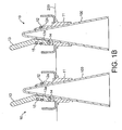
- FIGURE 1 B is a cross sectional view of two pin-less sockets as shown in FIGURE 1A with two wafer cones inserted therein.
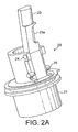
- FIGURE 2A is a perspective view of another pin-less socket in accordance with a second embodiment of the present invention.
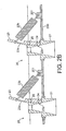
- FIGURE 2B is a cross sectional view of two pin-less sockets as shown in FIGURE 2A and showing an accompanying spring mechanism.
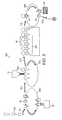
- FIGURE 3 is a simplified schematic of a single-loop manufacturing system including pin-less sockets of the present invention.
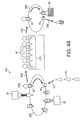
- FIGURES 4A and 4B are simplified schematics of two variations of multi-loop manufacturing systems including pin-less sockets of the present invention.
- FIGURE 5 is another simplified schematic of yet another relatively complex multi-loop manufacturing system including pin-less sockets of the present invention.
- FIGURE 1A is a perspective view of a pin-less socket 10 in accordance with a first embodiment of the present invention.
- the pin-less socket 10 is shown with a wafer cone 100 inserted therein.
- the pin-less socket 10 includes a socket 11 in the form of a truncated section that is conical and hollow.
- the socket is smooth and shaped to accept the bottom half of the wafer cone 100. It should be understood that wafer cones are fabricated in standard sizes that deviate very little cone to cone. Accordingly, the bottom half of wafer cone 100 may snugly fit into the socket 11 even with minor cone variations.
- the wafer cone 100 is held in place via a hook 13 that includes a hinge 14.
- An O-ring 12 located within a groove 12a surrounds the outside of the socket 11 to cause compression of the hook 13. Compression of the hook 13 causes one or more teeth (shown as 13a in FIGURE 1B ) to grip the tapered end of the wafer cone 100. A stop pin 15 limits the compression of the teeth that gives an end position of the hook. It should be noted that the tapered end of the cone is typically thicker than the rest of the cone. Due to this relative increased thickness, any damage to the cone is minimized.
- FIGURE 1B shows a cross sectional view of two pin-less sockets 10 as shown in FIGURE 1A with two wafer cones 100. From the FIGURE 1B cross-section, teeth 13a can be seen. It should be understood that this inverted position of the wafer cone 100 is considered to be a preferred manner of presenting the wafer cone 100 for spray coating from below. In such manner of coating, a more even distribution of spray coating (e.g., liquid chocolate) is possible with minimal over spray concerns.
- the hook 13 is normally in a compressed position by O-ring 12 or some similar circumferentially placed spring. Release of the wafer cone 100 is accomplished via movement of the hook 13 such that teeth 13a disengage from the wafer cone 100.
- Movement of the hook 13 may be facilitated in any known manner without straying from the intended scope of the present invention including the use of pistons, cams, or similar electromechanical mechanisms (not shown).
- a series of pin-less sockets 10 and associated wafer cones 100 can be held as shown within a flexible conveyor belt 200 to form part of an assembly line system.
- the present invention is advantageous in that the same pin-less socket 10 may form an integral part of many different such assembly line systems.
- FIGURE 2A is a perspective view of a pin-less socket 20 in accordance with a second embodiment of the present invention.
- the pin-less socket 20 is shown without any wafer cone inserted therein, though such wafer cone insertion is identical to that shown in regard to FIGURES 1A and 1B .
- the pin-less socket 20 includes a socket 21 in the form of a truncated section that is conical, hollow, and smoothly shaped to accept the bottom half of a wafer cone that is held in place via a hook 23 that includes a hinge 24.
- no circumferential compression mechanism is used.
- the hook 23 includes a section 23a modified to accept a spring (shown as 23b in FIGURE 2B ) to provide a lever-type action in order to cause compression of the hook 23.
- Lever-type action of the hook 23 causes one or more teeth (shown as 23c in FIGURE 2B ) to grip the tapered end of a wafer cone.
- a stop pin 25 limits the compression of the teeth that gives an end position of the hook.
- FIGURE 2B shows a cross sectional view of two pin-less sockets 20 as shown in FIGURE 2A .
- teeth 23c can be clearly seen as the wafer cones have been omitted for clarity.
- This inverted position of a wafer cone is considered to be a preferred orientation to enable spray coating from below because a more even distribution of spray coating (e.g., liquid chocolate) is possible with minimal over spray concerns.
- the hook 23 is normally in an engaged position by action of the spring 23b. Disengagement of the hook 23 is accomplished via lever-type movement of the hook 23 to counter the force of the spring 23b such that teeth 23c disengage from a wafer cone inserted therein (not shown for purposes of clarity).
- the use of the spring 23b allows a stronger, linear spring force and reduced friction.
- lever-type movement of the hook 23 may be facilitated in any known manner without straying from the intended scope of the present invention including the use of pistons, cams, or similar electromechanical mechanisms (not shown).
- a series of pin-less sockets 20 and associated wafer cones can be held as shown within a flexible conveyor belt 200 to form part of an assembly line system.
- this arrangement in accordance with the present invention would require a spring retention mechanism 201 located on the belt 200.
- the spring retention mechanism 201 could be formed integrally with the socket 21 by adding wider flanges on the socket 21.
- the present invention is advantageous in that the same pin-less socket 20 may form an integral part of many different such assembly line systems.
- FIGURES 3 , 4A , 4B , and 5 are simplified schematics of a various manufacturing systems in accordance with the present invention incorporating pin-less sockets of the present invention as shown in FIGURES 1A through 2B .
- pin-less socket version 10 or 20 may be used within the systems shown in FIGURES 3 , 4A , 4B , and 5 and various embodiments of the pin-less sockets 10, 20 may be possible without straying from the intended scope of the present invention.
- the schematics of FIGURES 3 , 4A , 4B , and 5 are simplified for purposes of illustrative clarity and therefore shown without regard to the specific detail of the pin-less socket of the present invention as such details have been discussed above.
- FIGURES 3 , 4A , 4B , and 5 are shown as systems to produce ball-top ice cream cones.
- the systems illustrated include both simpler ones that translate into less capital cost for a small assembly line with perhaps low volume and more complex ones (e.g., 3 or more conveyors) that translate into a higher capacity line. Any such system may clearly benefit from the incorporation of the inventive pin-less socket.
- FIGURE 3 is a simplified schematic of a single-loop manufacturing system 300 including pin-less sockets 30 of the present invention.
- FIGURE 3 includes a mask device 31 that may be of a heated trough-type that recycles over-spray for coating wafer cones 100 via a sprayer 32 from above.
- the wafer cones 100 are placed (arrow 501 ) either manually or via an automated manner such as shown by DE 20209984 using stacked cones into respective pin-less sockets 30 that are situated within a conveyor belt 200 that is shown rotating counter-clockwise.
- the conveyor belt 200 may be any known carrier mechanism so long as such mechanism is capable of supporting the pin-less sockets 30.
- the wafer cones 100 are first spray coated from above by the sprayer 32 with a chocolate coating in a manner well known in the art using or via the mask device 31.
- the coated wafer cone 100 is then moved along the conveyor belt 200 where the wafer cone 100 is filled with a semi-frozen confection (e.g., ice cream) via filler 33 in a manner well known in the art in order to form a ball-top 100a.
- the filled wafer cone 100 is then moved along the conveyor belt 200 to an area for cooling that includes a hardening tunnel 34.
- the filled and frozen wafer cone 100 is then moved along the conveyor belt 200 to a dipping area that includes a dipping bin 35.
- the dipping bin 35 may include more than one coating bin (not shown) that, for example, would add an outer layer of chocolate and subsequently an outer layer of nuts.
- the finished wafer cone 100 is then released (arrow 502) and packaged (not shown) in a manner well known in the art. It should be understood that a mechanism such as a cam, piston, lever, or similar mechanical device (not shown) is to be used to disengage the wafer cone 100 from engagement within the pin-less socket 30. While only a few pin-less sockets 30 are shown, it should be readily apparent that such sockets are spaced evenly along the entirety of the conveyor belt 200.
- FIGURES 4A and 4B show multi-loop assembly line systems 401, 402 in accordance with the present invention and include hardening tunnels 40 that can be any non-dedicated hardening tool commonly known throughout the art.
- FIGURE 4A includes three assembly loops.
- wafer cones 100 are placed (arrow 503 ) either manually or via an automated manner such as shown by DE 20209984 using stacked cones onto a conveyor belt 200.
- the wafer cones 100 are first spray coated from above by a sprayer 32 with a chocolate coating in a manner well known in the art using or via a mask device 31.
- a mask device 31 may be of a heated trough-type that recycles over spray.
- the wafer cone 100 is then filled with a semi-frozen confection (e.g., ice cream) via filler 33 in a manner well known in the art in order to form a ball-top 100a.
- a semi-frozen confection e.g., ice cream
- the filled wafer cone 100 is then transferred (arrow 504) via any known manner of automated "pick and place” mechanics to a second assembly loop that includes a hardening tunnel 40.
- the hardening tunnel 40 can be any non-dedicated hardening tool commonly known throughout the art.
- the filled and frozen wafer cone 100 is then transferred (arrow 505) via any known manner of automated "pick and place” mechanics to a third assembly loop that includes a conveyor belt 200 with multiple pin-less sockets 30 and a dipping bin 35.
- the dipping bin 35 may include more than one coating bin (not shown) that, for example, would add an outer layer of chocolate and subsequently an outer layer of nuts.
- the finished wafer cone 100 is then released (arrow 506) and packaged (not shown) in a manner well known in the art.
- a mechanism such as a cam, piston, lever, or similar mechanical device is to be used to disengage the wafer cone 100 from engagement within the pin-less socket 30.
- Each of the three assembly loops are shown as simplified rotating conveyor belts 200. While only a few pin-less sockets 30 are shown, it should be readily apparent that such sockets are spaced evenly along the entirety of the conveyor belt 200 of the third assembly loop.
- FIGURE 4B is another embodiment of a multi-loop manufacturing system in accordance with the present invention.
- FIGURE 4B differs from FIGURE 4A in that coating of the wafer cones 100 occurs from below while the wafer cones 100 are held in place by pin-less sockets 30.
- the wafer cones 100 are placed (arrow 507) either manually or in an automated manner using stacked cones into respective pin-less sockets 30 that are situated within a conveyor belt 200.
- the wafer cones 100 are first spray coated from below with a chocolate coating in a manner well known in the art using a sprayer 32.
- the wafer cone 100 is then moved along the conveyor belt 200 and filled with a semi-frozen confection (e.g., ice cream) via filler 33 in a manner well known in the art in order to form a ball-top 100a.
- a mechanism such as a cam, piston, lever, or similar mechanical device would be used to disengage the wafer cone 100 from engagement within the pin-less socket 30.
- the wafer cone 100 is then transferred (arrow 508) via any known manner of automated "pick and place" mechanics to a cooling area that includes a hardening tunnel 40.
- the hardening tunnel 40 can be any non-dedicated hardening tool commonly known throughout the art.
- the wafer cone is then transferred (arrow 509) via "pick and place” mechanisms or the like to a dipping area that includes a conveyor belt 200 with multiple pin-less sockets 30 and a dipping bin 35.
- the dipping bin 35 may include more than one coating bin (not shown) that, for example, would add an outer layer of chocolate and subsequently an outer layer of nuts.
- the finished wafer cone 100 is then released (arrow 510) and packaged (not shown) in a manner well known in the art in conjunction with a release mechanism (not shown) as mentioned above.
- Each assembly loop is shown as a simplified rotating conveyor belt 200. While only a few pin-less sockets 30 are shown in each of the first and third loops, it should be readily apparent that such pin-less sockets are spaced evenly along the entirety of the conveyor belts 200.
- FIGURE 5 shows yet another embodiment of a multi-loop manufacturing system in accordance with the present invention.
- four distinct loops are shown that separate the chocolate coating, ice cream filling, hardening, and nut dip stages.
- the assembly loops related to filling and hardening can be made via dedicated filling and hardening mechanisms well known in the art. Separating such stages into distinct loops helps to increase potential manufacturing volume.
- wafer cones 100 are placed (arrow 511) into pin-less sockets 30 either manually or in an automated manner such as shown by DE 20209984 using stacked cones onto a conveyor belt 200 that rotates counter clockwise.
- the wafer cones 100 then travel along the conveyor belt 200 and are spray coated from below with a chocolate coating in a manner well known in the art using a sprayer 32. After coating, the wafer cone 100 within its respective pin-less socket 30 is moved along the path of the conveyor belt 200 to an area where the wafer cone 100 is then transferred (arrow 512) via any known manner of automated "pick and place” mechanics to a filling second assembly loop that rotates clockwise (i.e., opposite the first loop) and includes a filler 33. It should be understood that a mechanism such as a cam, piston, lever, or similar mechanical device (not shown) is to be used to disengage the wafer cone 100 from engagement within the pin-less socket 30.
- a mechanism such as a cam, piston, lever, or similar mechanical device (not shown) is to be used to disengage the wafer cone 100 from engagement within the pin-less socket 30.
- the filler 33 fills the wafer cone 100 with a semi-frozen confection (e.g., ice cream) in a manner well known in the art in order to form a ball-top 100a.
- a semi-frozen confection e.g., ice cream
- the wafer cone 100 then transferred (arrow 513) via any known manner of automated "pick and place” mechanics to a cooling area that includes a hardening tunnel 40.
- the wafer cone continues via "pick and place” mechanics (arrow 514) to a dipping area that may include more than one coating bin 35 that, for example, would add an outer layer of chocolate and subsequently an outer layer of nuts.
- the finished wafer cone 100 is then released (arrow 515) and packaged (not shown) in a manner well known in the art.
- any mechanism such as a cam, piston, lever, or similar mechanical device (not shown) is to be used to disengage the wafer cone 100 from engagement within the pin-less socket 30 .
- any mechanism such as a cam, piston, lever, or similar mechanical device (not shown) is to be used to disengage the wafer cone 100 from engagement within the pin-less socket 30 .
- a cam, piston, lever, or similar mechanical device is to be used to disengage the wafer cone 100 from engagement within the pin-less socket 30 .
- pin-less sockets 30 are shown, such sockets are spaced evenly along the entirety of the conveyor belt 200.
Landscapes
- Life Sciences & Earth Sciences (AREA)
- Chemical & Material Sciences (AREA)
- Engineering & Computer Science (AREA)
- Food Science & Technology (AREA)
- Polymers & Plastics (AREA)
- Confectionery (AREA)
- Container, Conveyance, Adherence, Positioning, Of Wafer (AREA)
Claims (19)
- Stiftlose Aufnahmevorrichtung, wobei diese Vorrichtung aufweist:eine Aufnahme zum Aufnehmen eines konischen Nahrungsmittelprodukts darin;ein Gelenk, das sich auf einer Außenseite der Aufnahme befindet;einen Haken mit einem oder mehreren Zähnen, wobei der Haken über das Gelenk beweglich an der Aufnahme befestigt ist; undeine Kraft- bzw. Druckeinrichtung zum Halten des Hakens an seinem Platz innerhalb der Aufnahme, um das konische Nahrungsmittelprodukt festzuhalten.
- Vorrichtung gemäß Anspruch 1,wobei
die Aufnahme eine Vertiefung umfasst, die sich an ihrem Außenumfang befindet, und der Haken eine Kerbe umfasst, so dass die Vertiefung und die Kerbe eine ringförmige Nut bilden und die Druckeinrichtung sich in dieser Rille befindet. - Stiftlose Aufnahmevorrichtung gemäß Anspruch 2, wobei die Aufnahme eine Kegelstumpfform hat.
- Stiftlose Aufnahmevorrichtung gemäß Anspruch 3, wobei die Druckeinrichtung ein O-Ring mit elastischen Eigenschaften ist.
- Stiftlose Aufnahmevorrichtung gemäß Anspruch 3, wobei die Druckeinrichtung eine Spiralfeder ist.
- Stiftlose Aufnahmevorrichtung gemäß Anspruch 2, wobei die Vertiefung eine in Form und Größe entsprechende Öffnung umfasst, um die Bewegung des einen oder der mehreren Zähne hindurch zu erlauben.
- Stiftlose Aufnahmevorrichtung gemäß Anspruch 1, wobei
die Aufnahme eine Vertiefung umfasst, die sich an ihrem Außenumfang befindet, und der Haken eine Kerbe umfasst, so dass die Druckeinrichtung mit der Kerbe in einer Weise verbindbar ist, um eine hebelartige Bewegung des Hakens relativ zu dem Gelenk bereitzustellen. - Stiftlose Aufnahme gemäß Anspruch 7, wobei die Druckeinrichtung eine Linearfeder ist, die an einem Ende mit dem Haken an der Rille und an einem anderen Ende mit einem festen Punkt verbunden ist.
- Stiftlose Aufnahme gemäß Anspruch 8, wobei die Vertiefung eine in Form und Größe entsprechende Öffnung umfasst, um die Bewegung des einen oder der mehreren Zähne durch sie hindurch zu erlauben.
- Herstellungssystem zum Herstellen eines gefrorenen Konfekts, wobei dieses System aufweist:einen Überzugsbereich mit einer Überzugseinrichtung zum Überziehen einer Waffeltüte mit einer feuchtigkeitsbeständigen Schicht;einen Füllbereich mit einer Fülleinrichtung zum Einführen eines halbgefrorenen Konfekts in die Waffeltüte;undeinen Kühlbereich zum Aufnehmen der Waffeltüte mit dem halbgefrorenen Konfekt, der einen Verfestigungstunnel zum Einfrieren der Waffeltüte und des halbgefrorenen Konfekts umfasst;wobei der Überzugs- und/oder der Füll- und/oder der Kühlbereich mehr als eine stiftlose Aufnahmevorrichtung umfasst/en, wobei die Aufnahmevorrichtung umfasst:eine Aufnahme zum Aufnehmen der Waffeltüte darin, ein Gelenk auf einer Außenseite der Aufnahme, einen Haken mit einem oder mehr Zähnen, wobei der Haken über das Gelenk beweglich an der Aufnahme befestigt ist, und eine Druckeinrichtung zum Halten des einen oder der mehreren Zähne an ihrem Platz innerhalb der Aufnahme, um das kegelförmige Nahrungsmittelprodukt in der Aufnahme festzuhalten.
- System gemäß Anspruch 10, wobei das System ferner einen Eintauchbereich zum Bewegen der Waffeltüte durch einen Eintauchbehälter umfasst, wobei der Eintauchbereich mehr als eine der stiftlosen Aufnahmevorrichtungen umfasst, wobei die Aufnahmevorrichtung umfasst: die Aufnahme zum Aufnehmen der Waffeltüte darin, das Gelenk, das sich auf der Außenseite der Aufnahme befindet, den Haken mit einem oder mehr Zähnen, wobei der Haken über das Gelenk beweglich an der Aufnahme befestigt ist, und die Druckeinrichtung zum Halten des einen oder der mehreren Zähne an ihrem Platz innerhalb der Aufnahme, um das kegelförmige Nahrungsmittelprodukt mit der Aufnahme festzuhalten.
- System gemäß Anspruch 11, wobei die Aufnahme eine Vertiefung umfasst, die sich an ihrem Außenumfang befindet, und der Haken eine Kerbe umfasst, so dass die Vertiefung und die Kerbe eine ringförmige Rille bilden und die Druckeinrichtung sich innerhalb der Rille befindet.
- System gemäß Anspruch 11, wobei die Aufnahme eine Vertiefung umfasst, die sich an ihrem Außenumfang befindet, und der Haken eine Kerbe umfasst, so dass die Druckeinrichtung mit der Kerbe in einer Weise verbindbar ist, um die hebelartige Bewegung des Hakens relativ zu dem Gelenk bereitzustellen.
- System gemäß Anspruch 11, wobei der Überzugsbereich, der Füllbereich, der Kühlbereich und der Eintauchbereich zusammen eine einzige Herstellungsschleife bilden, und die mehr als eine stiftlose Aufnahmevorrichtungen die Waffeltüte jeweils durch den Überzugs-, den Füll-, den Kühl- und den Eintauchbereich befördern.
- System gemäß Anspruch 11, wobei der Überzugsbereich und der Füllbereich eine erste Herstellungsschleife bilden, wobei der Kühlbereich eine zweite Herstellungsschleife bildet/n, der Eintauchbereich eine dritte Herstellungsschleife bildet und die eine oder mehreren stiftlosen Aufnahmevorrichtungen sich in der dritten Herstellungsschleife befindet, um die Waffeltüte durch den Eintauchbereich zu befördern.
- System gemäß Anspruch 11, wobei der Überzugsbereich und der Füllbereich eine erste Herstellungsschleife bilden, der Kühlbereich eine zweite Herstellungsschleife bildet, der Eintauchbereich eine dritte Herstellungsschleife bildet, und die mehr als eine stiftlosen Aufnahmevorrichtungen sich in der ersten Herstellungsschleife und der dritten Herstellungsschleife befinden, um die Waffeltüte entsprechend durch Überzugs- und Füllbereiche und den Eintauchbereich zu befördern.
- System gemäß Anspruch 11, wobei der Überzugsbereich eine erste Herstellungsschleife bildet, der Füllbereich eine zweite Herstellungsschleife bildet, der Kühlbereich eine dritte Herstellungsschleife bildet, der Eintauchbereich eine vierte Herstellungsschleife bildet und die mehr als eine stiftlosen Aufnahmevorrichtungen sich sowohl in der ersten Herstellungsschleife als auch der vierten Herstellungsschleife befinden, um die Waffeltüte entsprechend durch die Überzugs- und Eintauchbereiche zu befördern.
- System gemäß Anspruch 11, wobei die Überzugseinrichtung die Waffeltüte von unterhalb der Waffeltüte überzieht, wenn die Waffeltüte von einer stiftlosen Aufnahmevorrichtung in einer umgekehrten Lage gehalten wird.
- System nach Anspruch 11, wobei die Überzugseinrichtung die Waffeltüte von oberhalb der Waffeltüte überzieht, wenn die Waffeltüte von einer stiftlosen Aufnahmevorrichtung in einer aufrechten Lage gehalten wird.
Applications Claiming Priority (2)
| Application Number | Priority Date | Filing Date | Title |
|---|---|---|---|
| US11/136,358 US7730831B2 (en) | 2005-05-25 | 2005-05-25 | Pin-less socket for frozen confections |
| PCT/EP2006/000899 WO2006125477A1 (en) | 2005-05-25 | 2006-02-02 | Pin-less socket for frozen confections |
Publications (2)
| Publication Number | Publication Date |
|---|---|
| EP1887878A1 EP1887878A1 (de) | 2008-02-20 |
| EP1887878B1 true EP1887878B1 (de) | 2009-09-09 |
Family
ID=36113592
Family Applications (1)
| Application Number | Title | Priority Date | Filing Date |
|---|---|---|---|
| EP06704235A Expired - Lifetime EP1887878B1 (de) | 2005-05-25 | 2006-02-02 | Stiftlose aufnahme für gefrorenes konfekt |
Country Status (8)
| Country | Link |
|---|---|
| US (1) | US7730831B2 (de) |
| EP (1) | EP1887878B1 (de) |
| AR (1) | AR053490A1 (de) |
| AT (1) | ATE442053T1 (de) |
| AU (1) | AU2006251441B2 (de) |
| DE (1) | DE602006009100D1 (de) |
| MX (1) | MX2007013863A (de) |
| WO (1) | WO2006125477A1 (de) |
Families Citing this family (12)
| Publication number | Priority date | Publication date | Assignee | Title |
|---|---|---|---|---|
| US10334868B2 (en) | 2016-06-16 | 2019-07-02 | Sigma Phase, Corp. | System for providing a single serving of a frozen confection |
| US10426180B1 (en) | 2016-06-16 | 2019-10-01 | Sigma Phase, Corp. | System for providing a single serving of a frozen confection |
| EP3471550A4 (de) | 2016-06-16 | 2020-02-26 | Sigma Phase, Corp. | System zur bereitstellung einer einzelportion einer gefrorenen süssware |
| JP7016143B2 (ja) * | 2017-11-07 | 2022-02-04 | 株式会社愛産製作所 | 冷菓の製造装置 |
| US10612835B2 (en) | 2018-08-17 | 2020-04-07 | Sigma Phase, Corp. | Rapidly cooling food and drinks |
| US11470855B2 (en) | 2018-08-17 | 2022-10-18 | Coldsnap, Corp. | Providing single servings of cooled foods and drinks |
| US10543978B1 (en) | 2018-08-17 | 2020-01-28 | Sigma Phase, Corp. | Rapidly cooling food and drinks |
| US11781808B2 (en) | 2019-04-09 | 2023-10-10 | Coldsnap, Corp. | Brewing and cooling a beverage |
| US11337438B2 (en) | 2020-01-15 | 2022-05-24 | Coldsnap, Corp. | Rapidly cooling food and drinks |
| TW202202790A (zh) | 2020-06-01 | 2022-01-16 | 美商寇德斯納普公司 | 用於快速冷卻食物及飲料的冷凍系統 |
| US20210368822A1 (en) | 2020-06-02 | 2021-12-02 | Samuel Messinger | System for producing and manufacturing of frozen confection product and method thereof |
| US11827402B2 (en) | 2021-02-02 | 2023-11-28 | Coldsnap, Corp. | Filling aluminum cans aseptically |
Family Cites Families (11)
| Publication number | Priority date | Publication date | Assignee | Title |
|---|---|---|---|---|
| US280464A (en) * | 1883-07-03 | giffoed | ||
| US1094113A (en) * | 1912-09-06 | 1914-04-21 | Paul Bissen | Well-pipe lifter. |
| US2334654A (en) * | 1941-05-06 | 1943-11-16 | Sportolari Frank | Method of forming coated frozen confections |
| US2719508A (en) * | 1950-03-14 | 1955-10-04 | Drumstick Inc | Holder for cone-shaped confections |
| US3985223A (en) | 1975-09-22 | 1976-10-12 | Fmc Corporation | Universal gripper assembly for frozen confections |
| SE8406107L (sv) * | 1984-12-03 | 1986-06-04 | Surtevall Trading Ab | Anordning for lasning av ett foremal mot ett anslag pa en stang, axel eller liknande |
| EP0925721A3 (de) | 1997-11-28 | 2000-03-29 | Tetra Pak Hoyer A/S | Handhabungsverfahren von Speiseeis-artikeln z.B. Hornwaffeltüten und Greifersystem hierfür |
| DK174118B1 (da) | 1998-05-01 | 2002-07-01 | Gram As | Tang til brug ved optagning af ispinde |
| US6698071B1 (en) * | 2002-02-19 | 2004-03-02 | Homax Products, Inc. | Clip systems and methods for sheet materials |
| DE20209984U1 (de) | 2002-06-27 | 2002-10-17 | TECON Spezialmaschinen GmbH, 41812 Erkelenz | Entstapelvorrichtung für Eiswaffeltüten |
| US7267075B2 (en) * | 2003-10-28 | 2007-09-11 | Norse Dairy Systems, Inc. | Modular and reconfigurable frozen cone confection manufacturing system and method |
-
2005
- 2005-05-25 US US11/136,358 patent/US7730831B2/en not_active Expired - Fee Related
-
2006
- 2006-02-02 DE DE602006009100T patent/DE602006009100D1/de not_active Expired - Fee Related
- 2006-02-02 EP EP06704235A patent/EP1887878B1/de not_active Expired - Lifetime
- 2006-02-02 AU AU2006251441A patent/AU2006251441B2/en not_active Ceased
- 2006-02-02 MX MX2007013863A patent/MX2007013863A/es unknown
- 2006-02-02 AT AT06704235T patent/ATE442053T1/de not_active IP Right Cessation
- 2006-02-02 WO PCT/EP2006/000899 patent/WO2006125477A1/en not_active Ceased
- 2006-05-24 AR ARP060102172A patent/AR053490A1/es unknown
Also Published As
| Publication number | Publication date |
|---|---|
| AU2006251441A1 (en) | 2006-11-30 |
| DE602006009100D1 (de) | 2009-10-22 |
| AU2006251441B2 (en) | 2012-01-19 |
| MX2007013863A (es) | 2008-01-24 |
| ATE442053T1 (de) | 2009-09-15 |
| WO2006125477A1 (en) | 2006-11-30 |
| AR053490A1 (es) | 2007-05-09 |
| US7730831B2 (en) | 2010-06-08 |
| EP1887878A1 (de) | 2008-02-20 |
| US20060280826A1 (en) | 2006-12-14 |
Similar Documents
| Publication | Publication Date | Title |
|---|---|---|
| EP1887878B1 (de) | Stiftlose aufnahme für gefrorenes konfekt | |
| US7267075B2 (en) | Modular and reconfigurable frozen cone confection manufacturing system and method | |
| AU645362B2 (en) | Methods and apparatus for creating a gelatin coating | |
| US5511361A (en) | Encapsulation method | |
| FR2501078A1 (fr) | Dispositif de nettoyage pour appareil distributeur de matieres fluides | |
| US7513213B2 (en) | Method, apparatus, and system for coating food items | |
| PL214038B1 (pl) | Sposób wytwarzania jadalnej oslonki na bazie tluszczu | |
| US20080149022A1 (en) | Conical shell grasping and retaining apparatus, method for coating inverted conical shells, and modular and reconfigurable frozen cone confection manufacturing system and method | |
| CA2508187C (en) | Pin-less socket for frozen confections | |
| AU2008293708B2 (en) | Apparatus and method of applying edible pearlescent coating to a food product | |
| US2282661A (en) | Device for handling and dipping confections | |
| US20090047393A1 (en) | System for combining ice cream and coatings | |
| HUT74496A (en) | Coating for ice confections | |
| CA2450086C (en) | Destacking device for ice-cream cones | |
| EP0547183A1 (de) | Vorrichtung zur herstellung von gefrorenen, essbaren produkten. | |
| CN116568147A (zh) | 用于将颗粒施加到冷冻甜食上的方法和装置 | |
| US2336649A (en) | Apparatus for forming coated frozen confections | |
| WO2012084505A1 (en) | Edible receptacles for frozen confections | |
| CA2484723C (en) | Conical shell grasping and retaining apparatus, method for coating inverted conical shells, and modular and reconfigurable frozen cone confection manufacturing system and method | |
| EP0631934A1 (de) | Schwerkraft-Zuführvorrichtung, z.B. zum Füllen von Behältern und entsprechendes Verfahren | |
| DK9300064U3 (da) | Chokoladeovertrækningsapparat for konfektureprodukter | |
| AU2006222381A1 (en) | Method and apparatus for decorating confectioneries | |
| KR20190089152A (ko) | 초코건빵 제조장치 | |
| DE10155599A1 (de) | Verfahren und Vorrichtung zum Aufnehmen und Übergeben kleinstückiger Artikel | |
| EP4648622A1 (de) | Kompaktes snackprodukt-beschichtungssystem |
Legal Events
| Date | Code | Title | Description |
|---|---|---|---|
| PUAI | Public reference made under article 153(3) epc to a published international application that has entered the european phase |
Free format text: ORIGINAL CODE: 0009012 |
|
| 17P | Request for examination filed |
Effective date: 20071227 |
|
| AK | Designated contracting states |
Kind code of ref document: A1 Designated state(s): AT BE BG CH CY CZ DE DK EE ES FI FR GB GR HU IE IS IT LI LT LU LV MC NL PL PT RO SE SI SK TR |
|
| 17Q | First examination report despatched |
Effective date: 20080530 |
|
| DAX | Request for extension of the european patent (deleted) | ||
| GRAP | Despatch of communication of intention to grant a patent |
Free format text: ORIGINAL CODE: EPIDOSNIGR1 |
|
| GRAS | Grant fee paid |
Free format text: ORIGINAL CODE: EPIDOSNIGR3 |
|
| GRAA | (expected) grant |
Free format text: ORIGINAL CODE: 0009210 |
|
| AK | Designated contracting states |
Kind code of ref document: B1 Designated state(s): AT BE BG CH CY CZ DE DK EE ES FI FR GB GR HU IE IS IT LI LT LU LV MC NL PL PT RO SE SI SK TR |
|
| REG | Reference to a national code |
Ref country code: GB Ref legal event code: FG4D |
|
| REG | Reference to a national code |
Ref country code: CH Ref legal event code: EP |
|
| REG | Reference to a national code |
Ref country code: IE Ref legal event code: FG4D |
|
| REF | Corresponds to: |
Ref document number: 602006009100 Country of ref document: DE Date of ref document: 20091022 Kind code of ref document: P |
|
| PG25 | Lapsed in a contracting state [announced via postgrant information from national office to epo] |
Ref country code: FI Free format text: LAPSE BECAUSE OF FAILURE TO SUBMIT A TRANSLATION OF THE DESCRIPTION OR TO PAY THE FEE WITHIN THE PRESCRIBED TIME-LIMIT Effective date: 20090909 Ref country code: LT Free format text: LAPSE BECAUSE OF FAILURE TO SUBMIT A TRANSLATION OF THE DESCRIPTION OR TO PAY THE FEE WITHIN THE PRESCRIBED TIME-LIMIT Effective date: 20090909 Ref country code: SE Free format text: LAPSE BECAUSE OF FAILURE TO SUBMIT A TRANSLATION OF THE DESCRIPTION OR TO PAY THE FEE WITHIN THE PRESCRIBED TIME-LIMIT Effective date: 20090909 |
|
| NLV1 | Nl: lapsed or annulled due to failure to fulfill the requirements of art. 29p and 29m of the patents act | ||
| LTIE | Lt: invalidation of european patent or patent extension |
Effective date: 20090909 |
|
| PG25 | Lapsed in a contracting state [announced via postgrant information from national office to epo] |
Ref country code: PL Free format text: LAPSE BECAUSE OF FAILURE TO SUBMIT A TRANSLATION OF THE DESCRIPTION OR TO PAY THE FEE WITHIN THE PRESCRIBED TIME-LIMIT Effective date: 20090909 Ref country code: NL Free format text: LAPSE BECAUSE OF FAILURE TO SUBMIT A TRANSLATION OF THE DESCRIPTION OR TO PAY THE FEE WITHIN THE PRESCRIBED TIME-LIMIT Effective date: 20090909 Ref country code: LV Free format text: LAPSE BECAUSE OF FAILURE TO SUBMIT A TRANSLATION OF THE DESCRIPTION OR TO PAY THE FEE WITHIN THE PRESCRIBED TIME-LIMIT Effective date: 20090909 Ref country code: SI Free format text: LAPSE BECAUSE OF FAILURE TO SUBMIT A TRANSLATION OF THE DESCRIPTION OR TO PAY THE FEE WITHIN THE PRESCRIBED TIME-LIMIT Effective date: 20090909 |
|
| PG25 | Lapsed in a contracting state [announced via postgrant information from national office to epo] |
Ref country code: CY Free format text: LAPSE BECAUSE OF FAILURE TO SUBMIT A TRANSLATION OF THE DESCRIPTION OR TO PAY THE FEE WITHIN THE PRESCRIBED TIME-LIMIT Effective date: 20090909 |
|
| PG25 | Lapsed in a contracting state [announced via postgrant information from national office to epo] |
Ref country code: ES Free format text: LAPSE BECAUSE OF FAILURE TO SUBMIT A TRANSLATION OF THE DESCRIPTION OR TO PAY THE FEE WITHIN THE PRESCRIBED TIME-LIMIT Effective date: 20091220 Ref country code: EE Free format text: LAPSE BECAUSE OF FAILURE TO SUBMIT A TRANSLATION OF THE DESCRIPTION OR TO PAY THE FEE WITHIN THE PRESCRIBED TIME-LIMIT Effective date: 20090909 Ref country code: IS Free format text: LAPSE BECAUSE OF FAILURE TO SUBMIT A TRANSLATION OF THE DESCRIPTION OR TO PAY THE FEE WITHIN THE PRESCRIBED TIME-LIMIT Effective date: 20100109 Ref country code: CZ Free format text: LAPSE BECAUSE OF FAILURE TO SUBMIT A TRANSLATION OF THE DESCRIPTION OR TO PAY THE FEE WITHIN THE PRESCRIBED TIME-LIMIT Effective date: 20090909 Ref country code: PT Free format text: LAPSE BECAUSE OF FAILURE TO SUBMIT A TRANSLATION OF THE DESCRIPTION OR TO PAY THE FEE WITHIN THE PRESCRIBED TIME-LIMIT Effective date: 20100111 Ref country code: RO Free format text: LAPSE BECAUSE OF FAILURE TO SUBMIT A TRANSLATION OF THE DESCRIPTION OR TO PAY THE FEE WITHIN THE PRESCRIBED TIME-LIMIT Effective date: 20090909 |
|
| PG25 | Lapsed in a contracting state [announced via postgrant information from national office to epo] |
Ref country code: SK Free format text: LAPSE BECAUSE OF FAILURE TO SUBMIT A TRANSLATION OF THE DESCRIPTION OR TO PAY THE FEE WITHIN THE PRESCRIBED TIME-LIMIT Effective date: 20090909 |
|
| PG25 | Lapsed in a contracting state [announced via postgrant information from national office to epo] |
Ref country code: BE Free format text: LAPSE BECAUSE OF FAILURE TO SUBMIT A TRANSLATION OF THE DESCRIPTION OR TO PAY THE FEE WITHIN THE PRESCRIBED TIME-LIMIT Effective date: 20090909 Ref country code: AT Free format text: LAPSE BECAUSE OF FAILURE TO SUBMIT A TRANSLATION OF THE DESCRIPTION OR TO PAY THE FEE WITHIN THE PRESCRIBED TIME-LIMIT Effective date: 20090909 |
|
| PLBE | No opposition filed within time limit |
Free format text: ORIGINAL CODE: 0009261 |
|
| STAA | Information on the status of an ep patent application or granted ep patent |
Free format text: STATUS: NO OPPOSITION FILED WITHIN TIME LIMIT |
|
| PG25 | Lapsed in a contracting state [announced via postgrant information from national office to epo] |
Ref country code: DK Free format text: LAPSE BECAUSE OF FAILURE TO SUBMIT A TRANSLATION OF THE DESCRIPTION OR TO PAY THE FEE WITHIN THE PRESCRIBED TIME-LIMIT Effective date: 20090909 |
|
| 26N | No opposition filed |
Effective date: 20100610 |
|
| REG | Reference to a national code |
Ref country code: CH Ref legal event code: PL |
|
| GBPC | Gb: european patent ceased through non-payment of renewal fee |
Effective date: 20100202 |
|
| PG25 | Lapsed in a contracting state [announced via postgrant information from national office to epo] |
Ref country code: MC Free format text: LAPSE BECAUSE OF NON-PAYMENT OF DUE FEES Effective date: 20100301 Ref country code: LI Free format text: LAPSE BECAUSE OF NON-PAYMENT OF DUE FEES Effective date: 20100228 Ref country code: GR Free format text: LAPSE BECAUSE OF FAILURE TO SUBMIT A TRANSLATION OF THE DESCRIPTION OR TO PAY THE FEE WITHIN THE PRESCRIBED TIME-LIMIT Effective date: 20091210 Ref country code: CH Free format text: LAPSE BECAUSE OF NON-PAYMENT OF DUE FEES Effective date: 20100228 |
|
| PG25 | Lapsed in a contracting state [announced via postgrant information from national office to epo] |
Ref country code: IE Free format text: LAPSE BECAUSE OF NON-PAYMENT OF DUE FEES Effective date: 20100202 |
|
| PG25 | Lapsed in a contracting state [announced via postgrant information from national office to epo] |
Ref country code: DE Free format text: LAPSE BECAUSE OF NON-PAYMENT OF DUE FEES Effective date: 20100901 |
|
| PG25 | Lapsed in a contracting state [announced via postgrant information from national office to epo] |
Ref country code: IT Free format text: LAPSE BECAUSE OF FAILURE TO SUBMIT A TRANSLATION OF THE DESCRIPTION OR TO PAY THE FEE WITHIN THE PRESCRIBED TIME-LIMIT Effective date: 20090909 Ref country code: GB Free format text: LAPSE BECAUSE OF NON-PAYMENT OF DUE FEES Effective date: 20100202 |
|
| PGFP | Annual fee paid to national office [announced via postgrant information from national office to epo] |
Ref country code: FR Payment date: 20120221 Year of fee payment: 7 |
|
| PG25 | Lapsed in a contracting state [announced via postgrant information from national office to epo] |
Ref country code: BG Free format text: LAPSE BECAUSE OF FAILURE TO SUBMIT A TRANSLATION OF THE DESCRIPTION OR TO PAY THE FEE WITHIN THE PRESCRIBED TIME-LIMIT Effective date: 20090909 Ref country code: HU Free format text: LAPSE BECAUSE OF FAILURE TO SUBMIT A TRANSLATION OF THE DESCRIPTION OR TO PAY THE FEE WITHIN THE PRESCRIBED TIME-LIMIT Effective date: 20100310 Ref country code: LU Free format text: LAPSE BECAUSE OF NON-PAYMENT OF DUE FEES Effective date: 20100202 |
|
| PG25 | Lapsed in a contracting state [announced via postgrant information from national office to epo] |
Ref country code: TR Free format text: LAPSE BECAUSE OF FAILURE TO SUBMIT A TRANSLATION OF THE DESCRIPTION OR TO PAY THE FEE WITHIN THE PRESCRIBED TIME-LIMIT Effective date: 20090909 |
|
| REG | Reference to a national code |
Ref country code: FR Ref legal event code: ST Effective date: 20131031 |
|
| PG25 | Lapsed in a contracting state [announced via postgrant information from national office to epo] |
Ref country code: FR Free format text: LAPSE BECAUSE OF NON-PAYMENT OF DUE FEES Effective date: 20130228 |