EP1887575A1 - Digitaler Videorecoder mit hierarchischen Speichern und Verfahren zur Implementierung hierarchischer Speicher - Google Patents
Digitaler Videorecoder mit hierarchischen Speichern und Verfahren zur Implementierung hierarchischer Speicher Download PDFInfo
- Publication number
- EP1887575A1 EP1887575A1 EP07113999A EP07113999A EP1887575A1 EP 1887575 A1 EP1887575 A1 EP 1887575A1 EP 07113999 A EP07113999 A EP 07113999A EP 07113999 A EP07113999 A EP 07113999A EP 1887575 A1 EP1887575 A1 EP 1887575A1
- Authority
- EP
- European Patent Office
- Prior art keywords
- stream data
- volatile memory
- area
- stored
- audio
- Prior art date
- Legal status (The legal status is an assumption and is not a legal conclusion. Google has not performed a legal analysis and makes no representation as to the accuracy of the status listed.)
- Granted
Links
Images


Classifications
-
- G—PHYSICS
- G11—INFORMATION STORAGE
- G11B—INFORMATION STORAGE BASED ON RELATIVE MOVEMENT BETWEEN RECORD CARRIER AND TRANSDUCER
- G11B20/00—Signal processing not specific to the method of recording or reproducing; Circuits therefor
- G11B20/10—Digital recording or reproducing
-
- H—ELECTRICITY
- H04—ELECTRIC COMMUNICATION TECHNIQUE
- H04N—PICTORIAL COMMUNICATION, e.g. TELEVISION
- H04N5/00—Details of television systems
- H04N5/76—Television signal recording
-
- G—PHYSICS
- G06—COMPUTING; CALCULATING OR COUNTING
- G06F—ELECTRIC DIGITAL DATA PROCESSING
- G06F12/00—Accessing, addressing or allocating within memory systems or architectures
- G06F12/02—Addressing or allocation; Relocation
- G06F12/08—Addressing or allocation; Relocation in hierarchically structured memory systems, e.g. virtual memory systems
- G06F12/0802—Addressing of a memory level in which the access to the desired data or data block requires associative addressing means, e.g. caches
- G06F12/0866—Addressing of a memory level in which the access to the desired data or data block requires associative addressing means, e.g. caches for peripheral storage systems, e.g. disk cache
-
- H—ELECTRICITY
- H04—ELECTRIC COMMUNICATION TECHNIQUE
- H04N—PICTORIAL COMMUNICATION, e.g. TELEVISION
- H04N5/00—Details of television systems
- H04N5/76—Television signal recording
- H04N5/907—Television signal recording using static stores, e.g. storage tubes or semiconductor memories
-
- G—PHYSICS
- G06—COMPUTING; CALCULATING OR COUNTING
- G06F—ELECTRIC DIGITAL DATA PROCESSING
- G06F2212/00—Indexing scheme relating to accessing, addressing or allocation within memory systems or architectures
- G06F2212/22—Employing cache memory using specific memory technology
- G06F2212/225—Hybrid cache memory, e.g. having both volatile and non-volatile portions
-
- G—PHYSICS
- G11—INFORMATION STORAGE
- G11B—INFORMATION STORAGE BASED ON RELATIVE MOVEMENT BETWEEN RECORD CARRIER AND TRANSDUCER
- G11B20/00—Signal processing not specific to the method of recording or reproducing; Circuits therefor
- G11B20/10—Digital recording or reproducing
- G11B20/10527—Audio or video recording; Data buffering arrangements
- G11B2020/1062—Data buffering arrangements, e.g. recording or playback buffers
- G11B2020/10629—Data buffering arrangements, e.g. recording or playback buffers the buffer having a specific structure
-
- G—PHYSICS
- G11—INFORMATION STORAGE
- G11B—INFORMATION STORAGE BASED ON RELATIVE MOVEMENT BETWEEN RECORD CARRIER AND TRANSDUCER
- G11B2220/00—Record carriers by type
- G11B2220/20—Disc-shaped record carriers
- G11B2220/25—Disc-shaped record carriers characterised in that the disc is based on a specific recording technology
- G11B2220/2508—Magnetic discs
- G11B2220/2516—Hard disks
-
- G—PHYSICS
- G11—INFORMATION STORAGE
- G11B—INFORMATION STORAGE BASED ON RELATIVE MOVEMENT BETWEEN RECORD CARRIER AND TRANSDUCER
- G11B2220/00—Record carriers by type
- G11B2220/40—Combinations of multiple record carriers
- G11B2220/45—Hierarchical combination of record carriers, e.g. HDD for fast access, optical discs for long term storage or tapes for backup
-
- G—PHYSICS
- G11—INFORMATION STORAGE
- G11B—INFORMATION STORAGE BASED ON RELATIVE MOVEMENT BETWEEN RECORD CARRIER AND TRANSDUCER
- G11B2220/00—Record carriers by type
- G11B2220/60—Solid state media
- G11B2220/61—Solid state media wherein solid state memory is used for storing A/V content
Definitions
- the present invention relates to a digital video recorder. More specifically, the present invention relates to a digital video recorder having hierarchical memories for efficient video recording and playing back and a method for implementing hierarchical memories.
- Digital broadcasting is progressing around the European standard of DVD (Digital Video Broadcasting) and the American FCC standard of ATV (Advanced TV), which is in compliance with the ATSC standard, which the U.S. adopted as the next-generation TV standard to replace the conventional analog standard of NTSC.
- a PVR Personal Video Recorder
- receives signals, transmitted from a broadcast station or outputted from a television converts the signals to digital information in real time, compresses the digital data into an MPEG2 file, and stores the data in a pre-installed hard disk (HD).
- the PVR then reads the stored data and outputs images, which are decoded in real time, to a display device.
- FIG. 1 is a block diagram showing the structure of a conventional PVR system.
- the PVR system includes an IR receiver 110, a processor 120, a memory 130, a tuner 140, a demultiplexer 150, a decoder 160, an output unit 170, an OSD unit 180, an IDE interface 185, and a hard disk drive 190.
- the IR receiver 110 receives remote control code information corresponding to a remote control operated by a user and transmits the remote control code information to the processor 120.
- the processor 120 translates a remote control code received from the IR receiver 110 and transmits remote control code translation information to a corresponding device. For example, if the remote control code translation information is a command to request a channel change, the processor 120 transmits the command to the tuner 140. Likewise, if the remote control code translation information is a command to record a program, the received broadcast data is controlled to be stored in the hard disk drive 190. If the remote control code translation information is a command to request a recording list, the recording list stored in the hard disk drive 190 is outputted through the output unit 170.
- the memory 130 can include a flash ROM, in which software for the operation of the PVR system is stored, and a DRAM, which stores a bitmap-type virtual screen that can be displayed through the output unit 170.
- the tuner 140 receives and outputs the broadcast signals, which are selected by the control of the processor 120.
- the demultiplexer 150 parses various kinds of information, such as audio, video, and other data, which are multiplexed in the broadcast signals supplied from the tuner 140.
- the decoder 160 decodes audio signals, video signals, and data signals, parsed by the demultiplexer 150, and processes these signals to visual and audio information that can be outputted through the output unit 170 such that the user can recognize these signals.
- the OSD unit 180 displays information corresponding to a particular command given by the processor 120. For instance, if a recording list output command is received from the processor 120, the OSD unit 180 controls the recording list extracted from the hard disk drive 190 to be displayed through the output unit 170.
- the IDE interface 185 receives transport packet (TP) data, transmitted from the demultiplexer 150 for recording, and provides the TD data to the hard disk drive 190. If a playback command is received from the processor 120, the IDE interface 185 transmits the data stored in the hard disk drive 190 to the decoder 160 through the processor 120.
- TP transport packet
- the hard disk drive 190 stores the TP data, transmitted from the IDE interface 185, that is, programs selected by the user through the recording command are stored in the hard disk drive 190.
- the hard disk drive While the hard disk drive is capable of storing a large amount of data at a low cost, the hard disk drive also has its own shortcomings over the flash memories, namely, slow access speeds, slow operation speeds, low durability, and short life.
- the durability and life of a hard disk drive can be an important factor that determines the durability and life of a digital recording device.
- the conventional digital recording device with a hard disk drive switches the hard disk drive to a stand-by mode or utilizes a large-capacity memory while the recording feature is not used.
- the duration of maintaining the hard disk drive in a stand-by mode is very limited. Equipping the digital recording device with a large-capacity memory costs a lot more than the hard disk drive. Being inevitably a machine device, the hard disk drive generates a great deal of noise and heat, which can be inappropriate for an appliance.
- One aspect of the present invention provides a digital video recorder having hierarchical memories and a method for implementing the hierarchical memories that can minimize the use of a hard disk drive by hierarchically utilizing storage means in accordance with characteristics of data.
- Another aspect of the present invention provides a digital video recorder having hierarchical memories and a method for implementing the hierarchical memories that can use data at a higher speed and minimize the use of a hard disk drive by placing a memory in between the hard disk drive, processor, and decoder to have the data stored and played back.
- Another aspect of the present invention features a digital video recorder.
- the digital video recorder in accordance with an embodiment of the present invention has a storage unit, which includes a volatile memory, a non-volatile memory, and a hard disk drive, and a memory controller, which controls audio and video streams successively outputted from a demultiplexer to be moved to and stored in the volatile memory, the non-volatile memory, and the hard disk drive in the order of the volatile memory, non-volatile memory, and hard disk drive.
- a storage unit which includes a volatile memory, a non-volatile memory, and a hard disk drive
- a memory controller which controls audio and video streams successively outputted from a demultiplexer to be moved to and stored in the volatile memory, the non-volatile memory, and the hard disk drive in the order of the volatile memory, non-volatile memory, and hard disk drive.
- a storage area of the volatile memory can be partitioned into a plurality of VM areas; each VM area can successively store audio and video streams by a designated size; and audio and video streams stored in a VM area, the storage space of which is completely used up, can be moved or copied to the non-volatile memory by the memory controller.
- a storage area of the non-volatile memory can be allotted into a plurality of partitioned areas including a buffering area and an NV storage area; audio and video streams stored in the VM area can be stored in the NV storage area; and audio and video streams stored in an NV storage area, the storage space of which is completely used up, can be moved or copied to the hard disk drive by the memory controller.
- the memory controller can control the audio and video streams stored in the VM area to be stored in the buffering area while the audio and video streams are moved or copied to the hard disk drive.
- the size of the buffering area can be expanded by the size of the NV storage area; the expanded buffering area can be re-designated as a new NV storage area; and a reduced NV storage area can be re-designated as a new buffering area.
- the stream data stored in the storage unit can be a PS (program stream) or a partial TS (transport stream).
- the digital video recorder in accordance with another embodiment of the present invention can include a storage unit, which includes a volatile memory, a non-volatile memory, and a hard disk drive, and a memory controller, which controls stream data stored in the hard disk drive to be moved or copied to the volatile memory or the non-volatile memory.
- a decoder can decode and output stream data stored in the volatile memory or the non-volatile memory.
- the memory controller can move or copy stream data in the size that can be decoded and played back by the decoder to the volatile memory, while stream data are moved or copied to the non-volatile memory.
- Stream data following the stream data written in the volatile memory, can be written in the non-volatile memory.
- the decoder can successively decode and output stream data stored in the non-volatile memory.
- the stream data can be a PS (program stream) or a partial TS (transport stream).
- Another aspect of the present invention features a method for storing and/or playing back stream data of a digital video recorder.
- the method for storing stream data of a digital video recorder in accordance with an embodiment of the present invention can include (a) moving and storing audio and video streams, which are successively outputted from a demultiplexer, in a non-volatile memory if the audio and video streams are accumulated in a volatile memory as stream data in a predetermined size and (b) if stream data in a predetermined size are accumulated in the non-volatile memory by repeating the above step (a), or accumulation of stream data of a corresponding broadcast program is completed, moving and storing the stream data in a hard disk drive.
- the step (a) can include i) starting an accumulation of stream data in the first partitioned area, ii) if the storage space of the first partitioned area is completely used up, controlling the accumulated stream data to be moved to and stored in the non-volatile memory and controlling stream data for succeeding audio and video streams to be accumulated in the second partitioned area, and iii) if the storage space of the second partitioned area is completed used up, controlling the accumulated stream data to be moved to and stored in the non-volatile memory and controlling stream data for succeeding audio and video streams to be accumulated in the first partitioned area.
- the step (b) can include i) starting an accumulation of the stream data in the NV storage area, and ii) if the storage space of the NV storage area is completely used up, controlling the accumulated stream data to be moved to and stored in the hard disk drive and controlling succeeding stream data to be accumulated in the buffering area.
- the buffering area can be expanded by the storage space of the NV storage area and be re-designated as a new NV storage area, and the remaining storage space can be re-designated as a new buffering area.
- the buffering area can have storage space that is sufficient to accumulate succeeding stream data while the stream data accumulated in the NV storage area are being moved and stored in the hard disk drive.
- the method for playing back stream data of a digital video recorder in accordance with another embodiment of the present invention can include i) having a certain size of stream data with an earlier playback order stored in a volatile memory, the stream data with an earlier playback order being among stream data stored in a hard disk, and ii) having stream data following the stream data, which are stored in the volatile memory, stored in a non-volatile memory.
- the size of the stream data stored in the volatile memory can be large enough to be played back while the succeeding stream data are stored in the non-volatile memory.
- a decoder can control the succeeding stream data stored in the non-volatile memory to be decoded, once decoding of the stream data stored in the volatile memory is completed.
- the stream data can be a PS (program stream) or a partial TS (transport stream).
- Still another aspect of the present invention features a recorded medium recording a method for storing and/or playing back stream data of a digital video recorder.
- the recorded medium tangibly embodies a program of instructions executable by a digital video recorder to execute a method for storing stream data.
- the program which is readable by the digital video recorder, can execute (a) moving and storing audio and video streams, which are successively outputted from a demultiplexer, in a non-volatile memory if the audio and video streams are accumulated in a volatile memory as stream data in a predetermined size, and (b) if stream data in a predetermined size are accumulated in the non-volatile memory by repeating the above step (a), or accumulation of stream data of a corresponding broadcast program is completed, moving and storing the stream data in a hard disk drive.
- the step (a) can include i) starting an accumulation of stream data in the first partitioned area, ii) if the storage space of the first partitioned area is completely used up, controlling the accumulated stream data to be moved to and stored in the non-volatile memory and controlling stream data for succeeding audio and video streams to be accumulated in the second partitioned area, and iii) if the storage space of the second partitioned area is completed used up, controlling the accumulated stream data to be moved to and stored in the non-volatile memory and controlling stream data for succeeding audio and video streams to be accumulated in the first partitioned area.
- the step (b) can include i) starting an accumulation of the stream data in the NV storage area, and ii) if the storage space of the NV storage area is completely used up, controlling the accumulated stream data to be moved to and stored in the hard disk drive and controlling succeeding stream data to be accumulated in the buffering area.
- the buffering area can be expanded by the storage space of the NV storage area and can be re-designated as a new NV storage area, and the remaining storage space can be re-designated as a new buffering area.
- the recorded medium tangibly embodies a program of instructions executable by a digital video recorder to execute a method for playing back stream data.
- the program which is readable by the digital video recorder, can execute i) having a certain size of stream data with an earlier playback order stored in a volatile memory, the stream data with an earlier playback order being among stream data stored in a hard disk, and ii) having stream data following the stream data, which are stored in the volatile memory, stored in a non-volatile memory.
- the size of the stream data stored in the volatile memory can be large enough to be played back while the succeeding stream data are stored in the non-volatile memory.
- first and second can be used in describing various elements, but the above elements shall not be restricted to the above terms. The above terms are used only to distinguish one element from the other. For instance, the first element can be named the second element, and vice versa, without departing the scope of claims of the present invention.
- the term “and/or” shall include the combination of a plurality of listed items or any of the plurality of listed items.
- FIG. 2 is a block diagram showing a digital video recorder in accordance with an embodiment of the present invention
- FIG. 3 is illustration of a hierarchical memory structure in accordance with an embodiment of the present invention.
- the digital video recorder in accordance with an embodiment of the present invention includes a tuner 210, a demultiplexer 220, a decoder 230, an output unit 240, a memory controller 250, and a storage unit 260.
- the storage unit 260 can include a volatile memory 270, a non-volatile memory, and a hard disk drive 290.
- the tuner 210 receives and outputs a broadcast signal, selected by the control of a playback processor (not shown).
- the playback processor can be a main processor that controls the operation of the digital video recorder.
- the demultiplexer 220 demultiplexes various kinds of information, such as audio, video, and other data that are multiplexed in broadcast signals supplied by the tuner 210.
- the demultiplexer 220 also demultiplexes a broadcast program, selected in accordance with the user's selection input, among broadcast signals received through the tuner and extracts the selected broadcast program to video and audio streams.
- the broadcast signal extracted and outputted by the demultiplexer 220 can be an MPEG data format, for example, program stream (PS) and/or partial transport stream (TS).
- the decoder 230 decodes the audio and video streams, parsed by the demultiplexer 220, and processes the decoded audio and video streams to visual information and audio information that can be outputted through the output unit 240 such that the user can recognize the information.
- the output unit 240 outputs the decoded audio and video signals, outputted from the decoder 230, to video and/or audio information.
- the output unit 240 can include a display and/or a speaker.
- the memory controller 250 designates the storage means to which the video and audio streams outputted from the demultiplexer 220 are to be stored and has the pertinent video and audio streams stored in accordance with the hierarchical structure of a plurality of storage means.
- the memory controller 250 also controls the stored data to be read and to be outputted through the output unit 240 in accordance with the hierarchical structure of the storage means.
- the storage unit 260 includes a volatile memory 270, non-volatile memory 280, and a hard disk drive 290.
- the video and audio streams that are stored in the storage means can be a form of PS and/or partial TS.
- the volatile memory 270 loses the stored data once the power is cut off.
- the volatile memory 270 can be a RAM, for example.
- the volatile memory 270 can be logically partitioned into a plurality of areas.
- the volatile memory can be partitioned into a first VM (volatile memory) area 310 and a second VM area 320, if the volatile memory 270 is divided into 2 areas.
- the non-volatile memory 270 is slower than the memory although it is possible to read/write in block units.
- the non-volatile memory 270 can be, for example, a flash memory.
- the non-volatile memory 270 can be logically partitioned into a plurality of areas.
- the non-volatile memory can be partitioned into a buffering area 330 and an NV (non-volatile) storage area 340.
- the hard disk drive 290 can store and maintain a large capacity of data, it is slow and noisy.
- the present invention maximizes the positive features and minimizes the negative features of the storage means to apply the hierarchical structure between the storage means.
- the memory controller 250 controls each of the storage means in the storage unit 260 as a hierarchical structure (i.e., data flow) of the volatile memory 270-non-volatile memory 280-hard disk drive 290, if the video and audio streams outputted from the demultiplexer 220 are stored in the storage means.
- the memory controller 250 controls the storage means as a hierarchical structure of the hard disk drive 290-non-volatile memory 280-volatile memory 270 or a hierarchical structure of the hard disk drive 290-volatile memory 270-non-volatile memory 280 if the data stored in each of the storage means are played back.
- FIGS. 3 to 5 will be referenced below to describe how the storage means of the digital video recorder are operated hierarchically in accordance with the present invention.
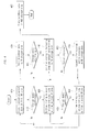
- FIG. 4 is a flow chart showing how the storage means are operated hierarchically, when data is written, in accordance with an embodiment of the present invention.
- the memory controller 250 stores the audio and video streams, outputted from the demultiplexer 220 in accordance with the user's command to store broadcast data, in the first VM area 310 of the volatile memory 270.
- step 415 the memory controller determines whether the storage space of the first VM area 310 is used up while storing the audio and video streams, successively outputted from the demultiplexer 220, in the first VM area 310 of the volatile memory 270.
- step 410 is repeated to continuously store the audio and video streams, outputted from the demultiplexer 220, in the first VM area 310 of the volatile memory 270.
- step 420 is performed to have the memory controller 250 store following audio and video streams in the second VM area 320.
- the memory controller 250 also controls the data stored in the first VM area 310 to be written in the NV storage area 340 of the non-volatile memory 270, in steps represented by 420 and 435.
- the storage space of the volatile memory 270 is divided into two or more partitioned areas, and if the audio and video streams fill up the storage space of one of the partitioned areas, succeeding audio and video streams will continue to be stored in another partitioned area. While the audio and video streams are stored in another partitioned area, the data written in the partitioned area, in which the preceding audio and video streams are stored, are stored in the NV storage area 340 of the non-volatile memory 270, and once the storing is completed, the data written in the pertinent partitioned area is deleted. For example, if the volatile memory consists of and sequentially use the first VM area 310 and the second VM area 320, as shown in FIG.
- the data written in the first VM area 310 is written in the NV storage area 340 of the non-volatile memory 280 while the audio and video streams are stored in the second VM area 320.
- all of the data written in the first VM area 310 will have to move to or be copied to the NV storage area 340 of the non-volatile memory 280 before completing the writing of the audio and video streams in the second VM area 320. If the writing of the audio and video streams is completed before the storage space of the first VM area 310 is used up, the second VM area 320 will no longer be used, and the audio and video streams written in the first VM area 310 will move to or be copied to the NV storage area 340 by the control of the memory controller 250.
- step 425 the memory controller 250 determines whether the storage space of the second VM area 320 is used up while storing the audio and video streams, successively outputted from the demultiplexer 220, in the second VM area 320 of the volatile memory 270.
- step 420 is repeated to have the audio and video streams, outputted from the demultiplexer 220, stored continuously in the second VM area 320 of the volatile memory 270.
- the first VM area 310 will no longer be used for writing the corresponding audio and video streams, and the audio and video streams written in the second VM area 320 will move to or be copied to the NV storage area 340 by the control of the memory controller 250.
- the memory controller 250 controls, in step 430, the succeeding audio and video streams to be stored in the first VM area 310.
- the memory controller 250 also controls the data written in the second VM area 320 to be written in the NV storage area 340 of the non-volatile memory 280, in steps 430 and 435.
- the memory controller 250 controls the audio and video streams, written in the first VM area 310 or the second VM area 320, to be stored in the NV storage area 340.
- the size of the NV storage area 340 corresponds to a capacity that can record an episode of a typical broadcast program.
- the recording capacity of a typical broadcast program may vary depending on the digital broadcast, but an approximate amount of 3.5G bytes is required for a 2-hour program since the DVB SD level has a bit rate of about 4Mbps.
- the size of the NV storage area 340 can be adjusted or preconfigured according to the bit rate of the broadcasting environment.
- step 440 the memory controller 250 determines whether the storage space of the NV storage area 340 is used up.
- step 435 is repeated to have the memory controller 250 control the audio and video streams, received from the first VM area 310 or the second VM area 320, to be continuously stored in the storage space of the NV storage area 340.
- step 445 is performed to have the memory controller 250 control the succeeding audio and video streams to be stored in the buffering area 330.
- the memory controller also controls the data written in the NV storage area 340 to be stored in a HDD storage area 350 of the hard disk drive 290, in steps 445 and 460.
- step 450 the memory controller 250 determines whether all of the audio and video streams written in the NV storage area 340 are moved to or copied to the hard disk drive 290.
- step 445 is repeated. If, however, all of the pertinent audio and video streams are moved to or copied to the hard disk drive, step 455 is performed to expand the buffering area 330 (i.e., the partitioned storage area of the non-volatile memory 280 to which the audio and video streams are presently moved from the volatile memory 270) to re-designate it as the NV storage area 340 and re-designates the remaining area as the buffering area 330.
- the buffering area 330 i.e., the partitioned storage area of the non-volatile memory 280 to which the audio and video streams are presently moved from the volatile memory 270
- the size of the buffering area 330 and NV storage area 340 can be maintained constant by expanding the buffering area 330 by the originally-designated size of the NV storage area 340 and re-designating the expanded buffering area 330 as the NV storage area 340.
- the original size of the buffering area 330 be at least large enough to store the audio and video stream, which are moved to or copied from the volatile memory 270, while all of the audio and video streams stored in the NV storage area 340 are moved or copied to the hard disk drive 290.
- the non-volatile memory 280 is logically partitioned into 2 or more storage areas in accordance with the present invention. Therefore, in case the storage space of any one partitioned area is used up, succeeding data can be written in another partitioned area while the data written in the used-up partitioned area are being moved or copied to the hard disk drive 290, thereby guaranteeing the data-sequencing.
- the NV storage area 340 is configured to have a storage capacity that can store all of the audio and video streams corresponding to one broadcast program, the storing of the succeeding audio and video streams in the buffering area 330 will not be performed. Moreover, if the storing of the audio and video streams according to the user's command to store a broadcast program is completed, the pertinent audio and video streams will be moved or copied to the hard disk drive 290. It is possible to determine whether all of the audio and video streams of a broadcast program corresponding to the user's storage command are stored, by using an assigned identifier or broadcast time corresponding to each broadcast program. Since the method of the above determination is well known to anyone skilled in the art, the pertinent description will not be provided herein.
- FIG. 5 is a flow chart showing a method for hierarchically operating storage means when playing back data in accordance with an embodiment of the present invention.
- the memory controller 250 controls the audio and video streams stored in the hard disk drive 290 to have audio and video streams of a certain size moved or copied (collectively refereed to as "copied", hereinafter) to the volatile memory (i.e., the first VM area 310 or the second VM area 320).
- the subject of copying the pertinent audio and video streams can be the memory controller 250.
- the playback controller or the memory controller 250 also controls the decoder 230 to decode the audio and video data stored in the volatile memory 270 and output the decoded audio and video data through the output unit 240.
- the minimum size of the audio and video streams copied to the volatile memory 270 should be sufficient for playing back until audio and video streams to be played back successively are completely copied from the hard disk drive 290 to the NV storage area 340 of the non-volatile memory.
- the memory controller 250 writes audio and video streams, which will be initially played back, in the volatile memory 270 because the data written in the volatile memory 270 can be processed more quickly. It shall be also evident that the audio and video streams to be played back initially can be copied to the buffering area 330 to have succeeding audio and video streams copied to the NV storage area 340 during the playback.
- step 520 the memory controller 250 copies audio and video streams, which succeed the audio and video stream copied to the volatile memory 270 through the above step 510, from the hard disk drive 290 to the NV storage area 340.
- the playback controller or the memory controller 250 controls the decoder 230 to decode the audio and video streams written in the NV storage area 340 of the non-volatile memory 280 and output the decoded audio and video data through the output unit 240.
- step 530 the memory controller 250 determines whether there remain audio and video streams to be successively played back in accordance with the broadcast program, which is presently played back, in the hard disk drive 290.
- the step 530 can be performed any time while playing back the audio and video streams that are copied to the NV storage area 340. However, since there can be audio and video streams to be successively played back, it would be preferable that the step 530 be performed prior to the time required to have some or all of the pertinent data copied in the volatile memory 270 or the buffering area 330.
- the step 530 and following steps can be omitted if the size of the storage space of the NV storage area 340 is configured to a capacity that can store one broadcast program or if audio and video streams to be successively played back are not present in the hard disk drive 290.
- the memory controller 250 controls, in step 540, the audio and video streams of a certain size, which follow the audio and video streams stored in the hard disk drive 290 that are copied to the NV storage area 340, to be copied to the volatile memory 270.
- the audio and video streams copied through the step 540 will be used for playback after the audio and video streams copied to the NV storage area 340 through the step 520 are completely played back.
- the pertinent audio and video streams can be copied to the buffering area 330.
- the step 540 is performed for the same reason as the step 510.
- step 550 the memory controller 250 controls audio and video streams that follow the audio and video streams written in the volatile memory 270 in the step 540 to be copied to the NV storage area 340 of the non-volatile memory 280.
- the step 550 can be omitted if the audio and video streams written in the volatile memory 270 or the buffering area 330 through the step 540 are the final audio and video streams for the corresponding broadcast program.
- the digital video recorder of the present invention copies a certain amount of data, for the audio and video streams written in the hard disk drive 290, to the volatile memory 270 or the non-volatile memory 280 and plays back the audio and video streams by using the copied data, rather than playing back the data from the hard disk drive 290, when playing back the audio and video streams written in the hard disk drive 290.
- the digital video recorder in accordance with the present invention can minimize the time required for storing the data and the stand-by time required for playing back the data, when writing the data in the storage unit 260 or performing the playback by using the data written in the storage unit 260. Furthermore, by allowing the hard disk drive 290 to be used only when all of the data stored in the non-volatile memory 280 are transferred to the hard disk drive 290 during the storing of the data or when all of the data stored in the hard disk drive 290 are transferred to the volatile memory 270 or the non-volatile memory 280 during the playback of the data., the use of the hard disk drive 290 can be minimized over the conventional data storage and playback methods.
Landscapes
- Engineering & Computer Science (AREA)
- Signal Processing (AREA)
- Theoretical Computer Science (AREA)
- Multimedia (AREA)
- Physics & Mathematics (AREA)
- General Engineering & Computer Science (AREA)
- General Physics & Mathematics (AREA)
- Signal Processing For Digital Recording And Reproducing (AREA)
- Television Signal Processing For Recording (AREA)
Applications Claiming Priority (1)
| Application Number | Priority Date | Filing Date | Title |
|---|---|---|---|
| KR1020060075348A KR100767605B1 (ko) | 2006-08-09 | 2006-08-09 | 계층적 메모리를 구비한 영상 기록 재생 장치 및 계층적메모리 구현 방법 |
Publications (2)
| Publication Number | Publication Date |
|---|---|
| EP1887575A1 true EP1887575A1 (de) | 2008-02-13 |
| EP1887575B1 EP1887575B1 (de) | 2010-10-06 |
Family
ID=38686034
Family Applications (1)
| Application Number | Title | Priority Date | Filing Date |
|---|---|---|---|
| EP07113999A Not-in-force EP1887575B1 (de) | 2006-08-09 | 2007-08-08 | Digitaler Videorecoder mit hierarchischen Speichern und Verfahren zur Implementierung hierarchischer Speicher |
Country Status (5)
| Country | Link |
|---|---|
| US (1) | US8189988B2 (de) |
| EP (1) | EP1887575B1 (de) |
| KR (1) | KR100767605B1 (de) |
| AT (1) | ATE484055T1 (de) |
| DE (1) | DE602007009608D1 (de) |
Cited By (2)
| Publication number | Priority date | Publication date | Assignee | Title |
|---|---|---|---|---|
| CN102984573A (zh) * | 2012-10-30 | 2013-03-20 | Tcl光电科技(惠州)有限公司 | 电视的数据存储方法和装置 |
| EP3155807A4 (de) * | 2014-07-14 | 2017-07-26 | NFL Enterprises LLC | Videowiedergabesysteme und -verfahren |
Families Citing this family (33)
| Publication number | Priority date | Publication date | Assignee | Title |
|---|---|---|---|---|
| US8341339B1 (en) | 2010-06-14 | 2012-12-25 | Western Digital Technologies, Inc. | Hybrid drive garbage collecting a non-volatile semiconductor memory by migrating valid data to a disk |
| US8959284B1 (en) | 2010-06-28 | 2015-02-17 | Western Digital Technologies, Inc. | Disk drive steering write data to write cache based on workload |
| US9146875B1 (en) | 2010-08-09 | 2015-09-29 | Western Digital Technologies, Inc. | Hybrid drive converting non-volatile semiconductor memory to read only based on life remaining |
| US9058280B1 (en) | 2010-08-13 | 2015-06-16 | Western Digital Technologies, Inc. | Hybrid drive migrating data from disk to non-volatile semiconductor memory based on accumulated access time |
| US8639872B1 (en) | 2010-08-13 | 2014-01-28 | Western Digital Technologies, Inc. | Hybrid drive comprising write cache spanning non-volatile semiconductor memory and disk |
| US9268499B1 (en) | 2010-08-13 | 2016-02-23 | Western Digital Technologies, Inc. | Hybrid drive migrating high workload data from disk to non-volatile semiconductor memory |
| US8775720B1 (en) | 2010-08-31 | 2014-07-08 | Western Digital Technologies, Inc. | Hybrid drive balancing execution times for non-volatile semiconductor memory and disk |
| US8683295B1 (en) | 2010-08-31 | 2014-03-25 | Western Digital Technologies, Inc. | Hybrid drive writing extended error correction code symbols to disk for data sectors stored in non-volatile semiconductor memory |
| US8782334B1 (en) | 2010-09-10 | 2014-07-15 | Western Digital Technologies, Inc. | Hybrid drive copying disk cache to non-volatile semiconductor memory |
| US8825977B1 (en) | 2010-09-28 | 2014-09-02 | Western Digital Technologies, Inc. | Hybrid drive writing copy of data to disk when non-volatile semiconductor memory nears end of life |
| US8825976B1 (en) | 2010-09-28 | 2014-09-02 | Western Digital Technologies, Inc. | Hybrid drive executing biased migration policy during host boot to migrate data to a non-volatile semiconductor memory |
| US8670205B1 (en) | 2010-09-29 | 2014-03-11 | Western Digital Technologies, Inc. | Hybrid drive changing power mode of disk channel when frequency of write data exceeds a threshold |
| US8699171B1 (en) | 2010-09-30 | 2014-04-15 | Western Digital Technologies, Inc. | Disk drive selecting head for write operation based on environmental condition |
| US8427771B1 (en) | 2010-10-21 | 2013-04-23 | Western Digital Technologies, Inc. | Hybrid drive storing copy of data in non-volatile semiconductor memory for suspect disk data sectors |
| US8612798B1 (en) | 2010-10-21 | 2013-12-17 | Western Digital Technologies, Inc. | Hybrid drive storing write data in non-volatile semiconductor memory if write verify of disk fails |
| US8429343B1 (en) | 2010-10-21 | 2013-04-23 | Western Digital Technologies, Inc. | Hybrid drive employing non-volatile semiconductor memory to facilitate refreshing disk |
| US8560759B1 (en) | 2010-10-25 | 2013-10-15 | Western Digital Technologies, Inc. | Hybrid drive storing redundant copies of data on disk and in non-volatile semiconductor memory based on read frequency |
| US9069475B1 (en) | 2010-10-26 | 2015-06-30 | Western Digital Technologies, Inc. | Hybrid drive selectively spinning up disk when powered on |
| US8630056B1 (en) | 2011-09-12 | 2014-01-14 | Western Digital Technologies, Inc. | Hybrid drive adjusting spin-up profile based on cache status of non-volatile semiconductor memory |
| US8909889B1 (en) | 2011-10-10 | 2014-12-09 | Western Digital Technologies, Inc. | Method and apparatus for servicing host commands by a disk drive |
| US8977804B1 (en) | 2011-11-21 | 2015-03-10 | Western Digital Technologies, Inc. | Varying data redundancy in storage systems |
| US8977803B2 (en) | 2011-11-21 | 2015-03-10 | Western Digital Technologies, Inc. | Disk drive data caching using a multi-tiered memory |
| US9268701B1 (en) | 2011-11-21 | 2016-02-23 | Western Digital Technologies, Inc. | Caching of data in data storage systems by managing the size of read and write cache based on a measurement of cache reliability |
| US8904091B1 (en) | 2011-12-22 | 2014-12-02 | Western Digital Technologies, Inc. | High performance media transport manager architecture for data storage systems |
| US8959281B1 (en) | 2012-11-09 | 2015-02-17 | Western Digital Technologies, Inc. | Data management for a storage device |
| WO2014128616A2 (en) * | 2013-02-22 | 2014-08-28 | Amit Kumar Jain Amit | Method of recording, editing and sharing an agglomeration of videos |
| US9141176B1 (en) | 2013-07-29 | 2015-09-22 | Western Digital Technologies, Inc. | Power management for data storage device |
| US9070379B2 (en) | 2013-08-28 | 2015-06-30 | Western Digital Technologies, Inc. | Data migration for data storage device |
| US8917471B1 (en) | 2013-10-29 | 2014-12-23 | Western Digital Technologies, Inc. | Power management for data storage device |
| US9323467B2 (en) | 2013-10-29 | 2016-04-26 | Western Digital Technologies, Inc. | Data storage device startup |
| US9195401B2 (en) * | 2014-02-18 | 2015-11-24 | University Of Florida Research Foundation, Inc. | Method and apparatus for virtual machine live storage migration in heterogeneous storage environment |
| KR101574273B1 (ko) | 2014-09-15 | 2015-12-03 | 주식회사 텔레칩스 | 모바일 단말을 위한 파일 캐시 기반의 타임쉬프트 처리 방법 및 이를 위한 컴퓨터로 판독가능한 기록매체 |
| US20220043588A1 (en) * | 2020-08-06 | 2022-02-10 | Micron Technology, Inc. | Localized memory traffic control for high-speed memory devices |
Citations (2)
| Publication number | Priority date | Publication date | Assignee | Title |
|---|---|---|---|---|
| US20040202073A1 (en) | 2003-04-09 | 2004-10-14 | Yung-Hsiao Lai | Systems and methods for caching multimedia data |
| EP1605453A2 (de) | 2004-06-10 | 2005-12-14 | Marvell World Trade Ltd. | Anpassungsfähiges Speichersystem |
Family Cites Families (6)
| Publication number | Priority date | Publication date | Assignee | Title |
|---|---|---|---|---|
| US6134631A (en) * | 1996-08-19 | 2000-10-17 | Hyundai Electronics America, Inc. | Non-volatile memory with embedded programmable controller |
| JP4264777B2 (ja) | 1999-05-31 | 2009-05-20 | ソニー株式会社 | データ再生方法及びデータ再生装置 |
| JP3902447B2 (ja) | 2001-11-07 | 2007-04-04 | 日本電気株式会社 | 階層伝送に対応したtsパケット多重方式 |
| JP2004112316A (ja) | 2002-09-18 | 2004-04-08 | Toshiba Corp | デジタル放送信号送出処理装置 |
| US20060051060A1 (en) * | 2003-07-03 | 2006-03-09 | Henry Dorovanessian | Method and system for digitally recording broadcast content |
| US20070223875A1 (en) * | 2006-03-21 | 2007-09-27 | Tsung-Ning Chung | Storage device and method of accessing storage device |
-
2006
- 2006-08-09 KR KR1020060075348A patent/KR100767605B1/ko active IP Right Grant
-
2007
- 2007-08-08 AT AT07113999T patent/ATE484055T1/de not_active IP Right Cessation
- 2007-08-08 US US11/835,816 patent/US8189988B2/en not_active Expired - Fee Related
- 2007-08-08 DE DE602007009608T patent/DE602007009608D1/de active Active
- 2007-08-08 EP EP07113999A patent/EP1887575B1/de not_active Not-in-force
Patent Citations (2)
| Publication number | Priority date | Publication date | Assignee | Title |
|---|---|---|---|---|
| US20040202073A1 (en) | 2003-04-09 | 2004-10-14 | Yung-Hsiao Lai | Systems and methods for caching multimedia data |
| EP1605453A2 (de) | 2004-06-10 | 2005-12-14 | Marvell World Trade Ltd. | Anpassungsfähiges Speichersystem |
Non-Patent Citations (4)
| Title |
|---|
| HU Y ET AL: "A NEW HIERARCHICALDISK ARCHITECTURE", IEEE MICRO, IEEE SERVICE CENTER, LOS ALAMITOS, CA, US, vol. 18, no. 6, November 1998 (1998-11-01), pages 64 - 76, XP000805934, ISSN: 0272-1732 * |
| HU, Y. ET AL.: "A new hierarchical disk architecture", IEEE MICRO, IEEE SERVICE CENTER, LOS ALAMITOS, CA, US, vol. 18, no. 6, November 1998 (1998-11-01), pages 64 - 76 |
| INTEL: "Digital Media Recorder", TECHNOLOGY BRIEF - CONSUMER ELECTRONICS, 2004, XP002461392 * |
| SEONG Y K ET AL: "Design and implementation of hard disk drive embedded digital satellite receiver with file management", IEEE TRANSACTIONS ON CONSUMER ELECTRONICS, IEEE SERVICE CENTER, NEW YORK, NY, US, vol. 48, no. 1, February 2002 (2002-02-01), pages 125 - 130, XP008086193, ISSN: 0098-3063 * |
Cited By (3)
| Publication number | Priority date | Publication date | Assignee | Title |
|---|---|---|---|---|
| CN102984573A (zh) * | 2012-10-30 | 2013-03-20 | Tcl光电科技(惠州)有限公司 | 电视的数据存储方法和装置 |
| EP3155807A4 (de) * | 2014-07-14 | 2017-07-26 | NFL Enterprises LLC | Videowiedergabesysteme und -verfahren |
| US10032478B2 (en) | 2014-07-14 | 2018-07-24 | NFL Enterprises LLC | Video replay systems and methods |
Also Published As
| Publication number | Publication date |
|---|---|
| KR100767605B1 (ko) | 2007-10-17 |
| US8189988B2 (en) | 2012-05-29 |
| DE602007009608D1 (de) | 2010-11-18 |
| ATE484055T1 (de) | 2010-10-15 |
| EP1887575B1 (de) | 2010-10-06 |
| US20080040537A1 (en) | 2008-02-14 |
Similar Documents
| Publication | Publication Date | Title |
|---|---|---|
| US8189988B2 (en) | Digital video recorder having hierarchical memories and method for implementing hierarchical memories | |
| US7995903B2 (en) | Data recording and reproducing apparatus and data recording and reproducing method | |
| EP1552690B1 (de) | Datenverwaltungsverfahren | |
| EP1239674B1 (de) | Aufnahme von Fernsehdaten | |
| JP4490823B2 (ja) | ディジタル・インタフェースを介したitvトリック・プレイ | |
| JP2006012225A (ja) | 情報処理装置 | |
| KR100770908B1 (ko) | 디지털 방송 스트림의 변속 재생 장치 및 방법 | |
| JP2011014948A (ja) | 画像符号化方法及び画像符号化装置、並びにそれらを用いた画像記録再生装置 | |
| US6978082B1 (en) | AV decoder control method and AV decoder control apparatus | |
| JP2002260336A (ja) | 情報記録再生方法及び情報記録再生装置 | |
| JP4532426B2 (ja) | 映像情報処理装置 | |
| JP3922199B2 (ja) | データ記録再生装置 | |
| JP2001157147A (ja) | 動画サムネイル表示機能を有するデジタル記録再生装置および動画サムネイル表示方法 | |
| EP1835502B1 (de) | Verfahren und Vorrichtung zum doppelten Speichern von streamed AV-Signalen für Zeitversetztesaufnahmefunktion. | |
| KR100610680B1 (ko) | 디지털 방송 녹화 편집장치 및 방법 | |
| US20070150440A1 (en) | Method and circuit for retrieving data | |
| KR100503459B1 (ko) | 오류파일 자동삭제 기능을 가지는 영상 기록/재생장치 및그에 따른 오류파일 자동 삭제 방법 | |
| JP5161852B2 (ja) | ドライブ装置、コンテンツ記録再生装置、データ書き込み方法、プログラムおよび記録媒体 | |
| CN1980358A (zh) | 不间断录像的方法及装置 | |
| KR100734105B1 (ko) | 미녹화분 없이 녹화하는 방법 및 장치 | |
| JP2008289057A (ja) | 録画装置 | |
| JP2008099081A (ja) | 記録再生装置 | |
| JP2009070432A (ja) | 情報再生装置 | |
| JP2009005393A (ja) | 放送番組装置及び記録済み番組表示方法 | |
| JP2008262605A (ja) | 情報再生装置 |
Legal Events
| Date | Code | Title | Description |
|---|---|---|---|
| PUAI | Public reference made under article 153(3) epc to a published international application that has entered the european phase |
Free format text: ORIGINAL CODE: 0009012 |
|
| AK | Designated contracting states |
Kind code of ref document: A1 Designated state(s): AT BE BG CH CY CZ DE DK EE ES FI FR GB GR HU IE IS IT LI LT LU LV MC MT NL PL PT RO SE SI SK TR |
|
| AX | Request for extension of the european patent |
Extension state: AL BA HR MK YU |
|
| 17P | Request for examination filed |
Effective date: 20080310 |
|
| 17Q | First examination report despatched |
Effective date: 20080409 |
|
| AKX | Designation fees paid |
Designated state(s): AT BE BG CH CY CZ DE DK EE ES FI FR GB GR HU IE IS IT LI LT LU LV MC MT NL PL PT RO SE SI SK TR |
|
| GRAP | Despatch of communication of intention to grant a patent |
Free format text: ORIGINAL CODE: EPIDOSNIGR1 |
|
| GRAS | Grant fee paid |
Free format text: ORIGINAL CODE: EPIDOSNIGR3 |
|
| GRAA | (expected) grant |
Free format text: ORIGINAL CODE: 0009210 |
|
| AK | Designated contracting states |
Kind code of ref document: B1 Designated state(s): AT BE BG CH CY CZ DE DK EE ES FI FR GB GR HU IE IS IT LI LT LU LV MC MT NL PL PT RO SE SI SK TR |
|
| REG | Reference to a national code |
Ref country code: GB Ref legal event code: FG4D |
|
| REG | Reference to a national code |
Ref country code: CH Ref legal event code: EP |
|
| REG | Reference to a national code |
Ref country code: IE Ref legal event code: FG4D |
|
| REF | Corresponds to: |
Ref document number: 602007009608 Country of ref document: DE Date of ref document: 20101118 Kind code of ref document: P |
|
| REG | Reference to a national code |
Ref country code: NL Ref legal event code: VDEP Effective date: 20101006 |
|
| PG25 | Lapsed in a contracting state [announced via postgrant information from national office to epo] |
Ref country code: SI Free format text: LAPSE BECAUSE OF FAILURE TO SUBMIT A TRANSLATION OF THE DESCRIPTION OR TO PAY THE FEE WITHIN THE PRESCRIBED TIME-LIMIT Effective date: 20101006 |
|
| LTIE | Lt: invalidation of european patent or patent extension |
Effective date: 20101006 |
|
| PG25 | Lapsed in a contracting state [announced via postgrant information from national office to epo] |
Ref country code: LT Free format text: LAPSE BECAUSE OF FAILURE TO SUBMIT A TRANSLATION OF THE DESCRIPTION OR TO PAY THE FEE WITHIN THE PRESCRIBED TIME-LIMIT Effective date: 20101006 |
|
| PG25 | Lapsed in a contracting state [announced via postgrant information from national office to epo] |
Ref country code: NL Free format text: LAPSE BECAUSE OF FAILURE TO SUBMIT A TRANSLATION OF THE DESCRIPTION OR TO PAY THE FEE WITHIN THE PRESCRIBED TIME-LIMIT Effective date: 20101006 Ref country code: AT Free format text: LAPSE BECAUSE OF FAILURE TO SUBMIT A TRANSLATION OF THE DESCRIPTION OR TO PAY THE FEE WITHIN THE PRESCRIBED TIME-LIMIT Effective date: 20101006 Ref country code: IS Free format text: LAPSE BECAUSE OF FAILURE TO SUBMIT A TRANSLATION OF THE DESCRIPTION OR TO PAY THE FEE WITHIN THE PRESCRIBED TIME-LIMIT Effective date: 20110206 Ref country code: PT Free format text: LAPSE BECAUSE OF FAILURE TO SUBMIT A TRANSLATION OF THE DESCRIPTION OR TO PAY THE FEE WITHIN THE PRESCRIBED TIME-LIMIT Effective date: 20110207 Ref country code: LV Free format text: LAPSE BECAUSE OF FAILURE TO SUBMIT A TRANSLATION OF THE DESCRIPTION OR TO PAY THE FEE WITHIN THE PRESCRIBED TIME-LIMIT Effective date: 20101006 Ref country code: FI Free format text: LAPSE BECAUSE OF FAILURE TO SUBMIT A TRANSLATION OF THE DESCRIPTION OR TO PAY THE FEE WITHIN THE PRESCRIBED TIME-LIMIT Effective date: 20101006 Ref country code: SE Free format text: LAPSE BECAUSE OF FAILURE TO SUBMIT A TRANSLATION OF THE DESCRIPTION OR TO PAY THE FEE WITHIN THE PRESCRIBED TIME-LIMIT Effective date: 20101006 Ref country code: BG Free format text: LAPSE BECAUSE OF FAILURE TO SUBMIT A TRANSLATION OF THE DESCRIPTION OR TO PAY THE FEE WITHIN THE PRESCRIBED TIME-LIMIT Effective date: 20110106 |
|
| PG25 | Lapsed in a contracting state [announced via postgrant information from national office to epo] |
Ref country code: GR Free format text: LAPSE BECAUSE OF FAILURE TO SUBMIT A TRANSLATION OF THE DESCRIPTION OR TO PAY THE FEE WITHIN THE PRESCRIBED TIME-LIMIT Effective date: 20110107 Ref country code: BE Free format text: LAPSE BECAUSE OF FAILURE TO SUBMIT A TRANSLATION OF THE DESCRIPTION OR TO PAY THE FEE WITHIN THE PRESCRIBED TIME-LIMIT Effective date: 20101006 |
|
| PG25 | Lapsed in a contracting state [announced via postgrant information from national office to epo] |
Ref country code: EE Free format text: LAPSE BECAUSE OF FAILURE TO SUBMIT A TRANSLATION OF THE DESCRIPTION OR TO PAY THE FEE WITHIN THE PRESCRIBED TIME-LIMIT Effective date: 20101006 Ref country code: ES Free format text: LAPSE BECAUSE OF FAILURE TO SUBMIT A TRANSLATION OF THE DESCRIPTION OR TO PAY THE FEE WITHIN THE PRESCRIBED TIME-LIMIT Effective date: 20110117 Ref country code: CZ Free format text: LAPSE BECAUSE OF FAILURE TO SUBMIT A TRANSLATION OF THE DESCRIPTION OR TO PAY THE FEE WITHIN THE PRESCRIBED TIME-LIMIT Effective date: 20101006 |
|
| PLBE | No opposition filed within time limit |
Free format text: ORIGINAL CODE: 0009261 |
|
| STAA | Information on the status of an ep patent application or granted ep patent |
Free format text: STATUS: NO OPPOSITION FILED WITHIN TIME LIMIT |
|
| PG25 | Lapsed in a contracting state [announced via postgrant information from national office to epo] |
Ref country code: DK Free format text: LAPSE BECAUSE OF FAILURE TO SUBMIT A TRANSLATION OF THE DESCRIPTION OR TO PAY THE FEE WITHIN THE PRESCRIBED TIME-LIMIT Effective date: 20101006 Ref country code: PL Free format text: LAPSE BECAUSE OF FAILURE TO SUBMIT A TRANSLATION OF THE DESCRIPTION OR TO PAY THE FEE WITHIN THE PRESCRIBED TIME-LIMIT Effective date: 20101006 Ref country code: RO Free format text: LAPSE BECAUSE OF FAILURE TO SUBMIT A TRANSLATION OF THE DESCRIPTION OR TO PAY THE FEE WITHIN THE PRESCRIBED TIME-LIMIT Effective date: 20101006 Ref country code: SK Free format text: LAPSE BECAUSE OF FAILURE TO SUBMIT A TRANSLATION OF THE DESCRIPTION OR TO PAY THE FEE WITHIN THE PRESCRIBED TIME-LIMIT Effective date: 20101006 |
|
| 26N | No opposition filed |
Effective date: 20110707 |
|
| REG | Reference to a national code |
Ref country code: DE Ref legal event code: R097 Ref document number: 602007009608 Country of ref document: DE Effective date: 20110707 |
|
| PG25 | Lapsed in a contracting state [announced via postgrant information from national office to epo] |
Ref country code: IT Free format text: LAPSE BECAUSE OF FAILURE TO SUBMIT A TRANSLATION OF THE DESCRIPTION OR TO PAY THE FEE WITHIN THE PRESCRIBED TIME-LIMIT Effective date: 20101006 Ref country code: MT Free format text: LAPSE BECAUSE OF FAILURE TO SUBMIT A TRANSLATION OF THE DESCRIPTION OR TO PAY THE FEE WITHIN THE PRESCRIBED TIME-LIMIT Effective date: 20101006 |
|
| PG25 | Lapsed in a contracting state [announced via postgrant information from national office to epo] |
Ref country code: MC Free format text: LAPSE BECAUSE OF NON-PAYMENT OF DUE FEES Effective date: 20110831 |
|
| REG | Reference to a national code |
Ref country code: CH Ref legal event code: PL |
|
| PG25 | Lapsed in a contracting state [announced via postgrant information from national office to epo] |
Ref country code: LI Free format text: LAPSE BECAUSE OF NON-PAYMENT OF DUE FEES Effective date: 20110831 Ref country code: CH Free format text: LAPSE BECAUSE OF NON-PAYMENT OF DUE FEES Effective date: 20110831 |
|
| REG | Reference to a national code |
Ref country code: IE Ref legal event code: MM4A |
|
| PG25 | Lapsed in a contracting state [announced via postgrant information from national office to epo] |
Ref country code: IE Free format text: LAPSE BECAUSE OF NON-PAYMENT OF DUE FEES Effective date: 20110808 |
|
| PG25 | Lapsed in a contracting state [announced via postgrant information from national office to epo] |
Ref country code: LU Free format text: LAPSE BECAUSE OF NON-PAYMENT OF DUE FEES Effective date: 20110808 Ref country code: CY Free format text: LAPSE BECAUSE OF EXPIRATION OF PROTECTION Effective date: 20101006 |
|
| PG25 | Lapsed in a contracting state [announced via postgrant information from national office to epo] |
Ref country code: TR Free format text: LAPSE BECAUSE OF FAILURE TO SUBMIT A TRANSLATION OF THE DESCRIPTION OR TO PAY THE FEE WITHIN THE PRESCRIBED TIME-LIMIT Effective date: 20101006 |
|
| PG25 | Lapsed in a contracting state [announced via postgrant information from national office to epo] |
Ref country code: HU Free format text: LAPSE BECAUSE OF FAILURE TO SUBMIT A TRANSLATION OF THE DESCRIPTION OR TO PAY THE FEE WITHIN THE PRESCRIBED TIME-LIMIT Effective date: 20101006 |
|
| REG | Reference to a national code |
Ref country code: FR Ref legal event code: PLFP Year of fee payment: 9 |
|
| REG | Reference to a national code |
Ref country code: FR Ref legal event code: PLFP Year of fee payment: 10 |
|
| REG | Reference to a national code |
Ref country code: DE Ref legal event code: R082 Ref document number: 602007009608 Country of ref document: DE Representative=s name: V. FUENER EBBINGHAUS FINCK HANO, DE |
|
| REG | Reference to a national code |
Ref country code: FR Ref legal event code: PLFP Year of fee payment: 11 |
|
| REG | Reference to a national code |
Ref country code: FR Ref legal event code: PLFP Year of fee payment: 12 |
|
| PGFP | Annual fee paid to national office [announced via postgrant information from national office to epo] |
Ref country code: DE Payment date: 20190723 Year of fee payment: 13 Ref country code: FR Payment date: 20190711 Year of fee payment: 13 |
|
| PGFP | Annual fee paid to national office [announced via postgrant information from national office to epo] |
Ref country code: GB Payment date: 20190814 Year of fee payment: 13 |
|
| REG | Reference to a national code |
Ref country code: DE Ref legal event code: R119 Ref document number: 602007009608 Country of ref document: DE |
|
| GBPC | Gb: european patent ceased through non-payment of renewal fee |
Effective date: 20200808 |
|
| PG25 | Lapsed in a contracting state [announced via postgrant information from national office to epo] |
Ref country code: FR Free format text: LAPSE BECAUSE OF NON-PAYMENT OF DUE FEES Effective date: 20200831 Ref country code: DE Free format text: LAPSE BECAUSE OF NON-PAYMENT OF DUE FEES Effective date: 20210302 |
|
| PG25 | Lapsed in a contracting state [announced via postgrant information from national office to epo] |
Ref country code: GB Free format text: LAPSE BECAUSE OF NON-PAYMENT OF DUE FEES Effective date: 20200808 |