EP1883443B1 - Low profile introducer apparatus - Google Patents
Low profile introducer apparatus Download PDFInfo
- Publication number
- EP1883443B1 EP1883443B1 EP06771252A EP06771252A EP1883443B1 EP 1883443 B1 EP1883443 B1 EP 1883443B1 EP 06771252 A EP06771252 A EP 06771252A EP 06771252 A EP06771252 A EP 06771252A EP 1883443 B1 EP1883443 B1 EP 1883443B1
- Authority
- EP
- European Patent Office
- Prior art keywords
- outer sleeve
- distal
- inner cannula
- inch
- pushed
- Prior art date
- Legal status (The legal status is an assumption and is not a legal conclusion. Google has not performed a legal analysis and makes no representation as to the accuracy of the status listed.)
- Active
Links
Images

Classifications
-
- A—HUMAN NECESSITIES
- A61—MEDICAL OR VETERINARY SCIENCE; HYGIENE
- A61M—DEVICES FOR INTRODUCING MEDIA INTO, OR ONTO, THE BODY; DEVICES FOR TRANSDUCING BODY MEDIA OR FOR TAKING MEDIA FROM THE BODY; DEVICES FOR PRODUCING OR ENDING SLEEP OR STUPOR
- A61M25/00—Catheters; Hollow probes
- A61M25/01—Introducing, guiding, advancing, emplacing or holding catheters
- A61M25/06—Body-piercing guide needles or the like
- A61M25/065—Guide needles
-
- A—HUMAN NECESSITIES
- A61—MEDICAL OR VETERINARY SCIENCE; HYGIENE
- A61B—DIAGNOSIS; SURGERY; IDENTIFICATION
- A61B17/00—Surgical instruments, devices or methods
- A61B17/34—Trocars; Puncturing needles
- A61B17/3415—Trocars; Puncturing needles for introducing tubes or catheters, e.g. gastrostomy tubes, drain catheters
-
- A—HUMAN NECESSITIES
- A61—MEDICAL OR VETERINARY SCIENCE; HYGIENE
- A61B—DIAGNOSIS; SURGERY; IDENTIFICATION
- A61B17/00—Surgical instruments, devices or methods
- A61B17/34—Trocars; Puncturing needles
- A61B17/3417—Details of tips or shafts, e.g. grooves, expandable, bendable; Multiple coaxial sliding cannulas, e.g. for dilating
- A61B17/3421—Cannulas
- A61B17/3423—Access ports, e.g. toroid shape introducers for instruments or hands
-
- A—HUMAN NECESSITIES
- A61—MEDICAL OR VETERINARY SCIENCE; HYGIENE
- A61M—DEVICES FOR INTRODUCING MEDIA INTO, OR ONTO, THE BODY; DEVICES FOR TRANSDUCING BODY MEDIA OR FOR TAKING MEDIA FROM THE BODY; DEVICES FOR PRODUCING OR ENDING SLEEP OR STUPOR
- A61M25/00—Catheters; Hollow probes
- A61M25/01—Introducing, guiding, advancing, emplacing or holding catheters
- A61M25/06—Body-piercing guide needles or the like
- A61M25/0662—Guide tubes
-
- A—HUMAN NECESSITIES
- A61—MEDICAL OR VETERINARY SCIENCE; HYGIENE
- A61M—DEVICES FOR INTRODUCING MEDIA INTO, OR ONTO, THE BODY; DEVICES FOR TRANSDUCING BODY MEDIA OR FOR TAKING MEDIA FROM THE BODY; DEVICES FOR PRODUCING OR ENDING SLEEP OR STUPOR
- A61M25/00—Catheters; Hollow probes
- A61M25/01—Introducing, guiding, advancing, emplacing or holding catheters
- A61M25/09—Guide wires
- A61M25/09041—Mechanisms for insertion of guide wires
-
- A—HUMAN NECESSITIES
- A61—MEDICAL OR VETERINARY SCIENCE; HYGIENE
- A61M—DEVICES FOR INTRODUCING MEDIA INTO, OR ONTO, THE BODY; DEVICES FOR TRANSDUCING BODY MEDIA OR FOR TAKING MEDIA FROM THE BODY; DEVICES FOR PRODUCING OR ENDING SLEEP OR STUPOR
- A61M25/00—Catheters; Hollow probes
- A61M25/01—Introducing, guiding, advancing, emplacing or holding catheters
- A61M25/09—Guide wires
- A61M2025/09175—Guide wires having specific characteristics at the distal tip
-
- A—HUMAN NECESSITIES
- A61—MEDICAL OR VETERINARY SCIENCE; HYGIENE
- A61M—DEVICES FOR INTRODUCING MEDIA INTO, OR ONTO, THE BODY; DEVICES FOR TRANSDUCING BODY MEDIA OR FOR TAKING MEDIA FROM THE BODY; DEVICES FOR PRODUCING OR ENDING SLEEP OR STUPOR
- A61M25/00—Catheters; Hollow probes
- A61M25/0009—Making of catheters or other medical or surgical tubes
- A61M25/001—Forming the tip of a catheter, e.g. bevelling process, join or taper
Definitions
- This invention relates to the field of percutaneous access to the vascular system. More specifically, this invention relates to a low profile apparatus used to introduce catheters and other interventional devices into the vascular system with small gauge needles.
- interventional medical devices such as a catheter
- interventional devices are used for, among otherthings, blood pressure monitoring, blood sampling, and the administration of fluids and medicaments to a patient.
- Such devices are introduced using the well-known Seldinger percutaneous entry technique.
- the Seldinger technique for percutaneous entry into the vascular system has been in widespread use in diagnostic and interventional medicine for many years.
- the physician makes an oblique entry into the artery or vein with a beveled needle.
- a wire guide is passed into the proximal end of the needle, through the length of the needle and into the artery or vein.
- the needle is thereafter withdrawn, leaving the wire guide in place.
- the catheter or other interventional device is then passed over the wire guide, through the puncture, and into the artery or vein at the needle puncture site. Once the catheter is in place, the wire guide can be withdrawn.
- wire guides are normally comprised of a tightly wound helical stainless steel wire coil.
- outer diameter O. D.
- This diameter of wire guide will typically pass through an 18 gauge thinwall needle.
- An 18 gauge needle typically has a 1.27 mm (0.050 inch) outer diameter and a 1.07 mm (0.042 inch) inner diameter.
- the 18 gauge needle is the most common sized needle used for initial vascular access, and has become a standard needle for use with the Seldinger technique for percutaneous catheterization.
- the outer diameter of an 18 gauge needle is just large enough to damage tissue or cause excessive bleeding if it does not enter the vessel correctly, or if it inadvertently penetrates an organ or other unintended body structure.
- Needles of 21 gauge thinwall, or smaller are considered small enough that they do not damage tissue or organs, or cause excessive bleeding if inserted off target.
- needles having smaller outer diameters generally have correspondingly shorter bevels at the needle tip compared to the size of the bevel tip of an 18 gauge needle. Thus, it is much easier to get a short bevel into the lumen of a small vessel than the longer bevel of the 18 gauge needle.
- the bore of a needle of 21 gauge, or smaller is not large enough to pass a standard 0.89 mm or 0.97 mm (0.035 inch or 0.038 inch) diameter wire guide therethrough.
- the largest wire guide that can be easily introduced into such small gauge needles is normally a wire of 0.46 mm (0.018 inch) outer diameter.
- many diagnostic and interventional devices need at least a 0.89 mm (0.035 inch), and more preferably a 0.97 mm (0.038 inch), diameter wire guide to provide sufficient support to optimally introduce and manipulate such devices through the vasculature.
- Patent No.4,650,472 (“the '472 patent”), assigned to the assignee herein, describes a catheterization apparatus which allows a smaller gauge needle, such as a 22 gauge (0.72 mm; 0.028 inch O.D.) needle, to be used for the initial puncture through the skin of the patient in place of the larger conventional 18 gauge needle.
- a 0.46 mm (0.018 inch) outer diameter wire guide is initially inserted through the bore of the small gauge (e.g. 22 gauge) needle.
- the needle is thereafter withdrawn, and a removable inner cannula, or dilator, is provided over the wire guide but inside an outer sleeve portion of the catheterization apparatus.
- This removable inner cannula has a tapered tip, and provides a transition between the large distal opening of the outer sleeve and the 0.46 mm (0.018 inch) wire guide.
- the inner cannula is generally about 0.97 mm (0.038 inch) O.D., and the outer sleeve is sized to fit over the inner cannula.
- the outer sleeve and the inner cannula of the apparatus disclosed in the '472 patent are normally inserted into the blood vessel in tandem.
- the diametrical transition of the leading end of this tandem is intended to minimize the trauma that may otherwise be caused by the insertion of a large diameter outer sleeve over a small diameter wire guide.
- the outer sleeve can thereafter be removed from the patient, leaving the larger wire guide in the vessel ready to accept a catheter or other interventional device, as in the standard Seldinger technique.
- the apparatus of the '472 patent has been successfully used to percutaneously insert a catheter having a large diameter O.D. into a blood vessel when the initial insertion is made with an introducer needle and a wire guide which are much smaller in diameter than the distal opening of the catheter.
- the apparatus of the '472 patent thus enables the physician to introduce larger diagnostic and interventional devices into a vessel than would otherwise be possible when the initial vessel entry is made with a small gauge needle.
- the physician When the apparatus is inserted into the vessel as described, however, the physician must exert sufficient force to overcome the resistance provided at the "bump" that is present at the transition between the distal end of the outer sleeve and the underlying portion of the inner cannula.
- the side of the vessel opposite the initial stick may be punctured. Although such insertions may be safely performed, it is nonetheless desired to further minimize the amount of force required to insert the outer sleeve into the vessel, and to reduce the possibility that the physician may inadvertently puncture any portion of the vessel wall.
- proximal and distal will be used to describe the opposing axial ends of the inventive apparatus, as well as the axial ends of various related components.
- proximal is used in its conventional sense to refer to the end of the apparatus (or component) that is closest to the operator during use of the collar.
- distal is used in its conventional sense to refer to the end of the apparatus (or component) that is initially inserted into the patient, or that is closest to the patient.
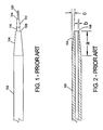
- Fig. 1 illustrates one embodiment of a prior art apparatus 100 for effecting catheterization of a body vessel using a small gauge introducer needle. The apparatus shown in Fig. 1 is further described in U.S. Patent No. 4,650,472 .
- Fig. 1 illustrates the dimensional relationship between outer sleeve 102, inner cannula 110 and wire guide 120 at the distal end portion of prior art apparatus 100.
- Outer sleeve 102 includes a distal portion 104 that tapers to outer sleeve distal end 106.
- Inner cannula 110 also includes a distal portion 112 that tapers to inner cannula distal end 114.
- Wire guide 120 extends from inner cannula distal end 114 in the normal fashion.
- Fig. 2 is a sectional view of outer sleeve 102, shown removed from apparatus 100.
- tapered area a in this prior art apparatus is approximately 4 ( ⁇ 1) mm long.
- the thickness b of the wall of sleeve 102 at distal end 106 is about 0.1016 ( ⁇ 0.0005) mm (0.004 inch).
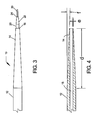
- Fig. 4 is a sectional view of the outer sleeve of the apparatus of Fig. 3 ;
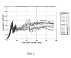
- Fig. 5 is a graph illustrating the relationship between compressive extension and compressive load for specimens 1-15 of an embodiment of the inventive apparatus
- the thickness e of the wall of sleeve 12 at distal end 16 is less than 0.076 mm (0.003 inch).
- thickness e is between about 0.0127 mm (0.0005) and 0.038 mm (0.0015 inch), and most preferably, about 0.0254 mm (0.001 inch).
- the angle f of taper of tapered area 14 from the longitudinal axis is less than about 2.5°, preferably between about 0.5° and about 2°, and more preferably between 0.5° and 2°, or from about 1 ° to about 1.5° and most preferably 1°.
- the exact angle of taper will preferably correspond to the remaining dimensions of the outer sleeve and inner cannula such that a generally smooth transition is provided between the distal end of the sleeve and the outer surface of the inner cannula.
- the inventive apparatus 10 can be of any conventional size for its intended purposes.
- the outer sleeve 12 is between about 1.32 mm and 1.98 mm (4 and 6 French) and most preferably, about 1.65 mm (5 French).
- the lumen 15 of the outer sleeve preferably has a diameter of about 1.016 mm (0.04 inch).
- Inner cannula 20 is sized to fit within the lumen of outer sleeve 12 in conventional fashion for such devices.
- FIG. 3 One example of the gradual transition of the outer surface of outer sleeve 12 of the inventive apparatus to the inner cannula 20 is shown in Fig. 3 .
- This transition is much smoother, avoids the substantial shoulder represented by the dimension b of Figure 2 , and occurs in a much more gradual manner over a greater tapered length 14 of the outer sleeve, when compared to the much more abrupt transition of the tapered portion 104 of the prior art device shown in Fig. 1 .
- the smooth, gradual transition of the inventive apparatus provides a very sleek profile that enables the apparatus to be smoothly inserted into, and passed through, the initial body opening and the underlying tissue. This results in a reduction of the trauma experienced by the patient at the insertion point.
- the step or shoulder represented by the wall thickness of the outer sleeve at the distal end is preferably 10% or less than the external radius of the outer sleeve at its full (non-tapered) diameter, more preferably 5% or less, still more preferably 3% or less.
- the inventive apparatus included an outer sleeve having a tapered portion of about 15 mm, and forming an angle of about 1 with the longitudinal axis.
- the thickness of the wall of the outer sleeve at its distal end was about 0.0254 mm (0.001 inch).
- the comparative reference apparatus included an outer sleeve having a tapered portion of about 4 mm, and forming an angle of about 3° with the longitudinal axis.
- the thickness of the wall of the outer sleeve at its distal end was about 0.1016 mm (0.004 inch).
- Simulations were performed on thirty specimens of the inventive apparatus and thirty specimens of the conventional apparatus.
- the testing conditions were identical on all specimens, with the exception of the structural differences in the outer sleeves of the respective apparatuses as described.
- the tests were designed to simulate the compressive load (in newton) that is exerted on the skin as the introducer apparatus initially enters the skin through the puncture, and as the introducer apparatus is continuously inserted to a depth (or compressive extension) of about 50 mm.
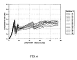
- Table 1 The data of Table 1 is illustrated graphically in Fig. 5 for specimens 1 to 15, and in Fig. 6 for specimens 16 to 30 of the inventive apparatus.
- the "zero point" (“0") of the “compressive extension” and the “compressive load” represents the point where the inner cannula initially touches the sheet as it is urged forwardly for insertion.
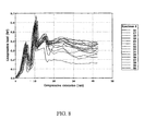
- Table 2 The data of Table 2 is illustrated graphically in Fig. 7 for specimens 1 to 15, and in Fig. 8 for specimens 16 to 30 of the reference apparatus.
- the x-axis of the graphs represents the compressive extension, or in other words, the length of insertion (in mm) of the apparatus through the skin.
- the y-axis of the graph represents the compressive load, or in other words, the force (in N) that is exerted by the physician upon insertion of the apparatus through the skin.
- the compressive load gradually builds as the apparatus is advanced into the skin until the inner cannula has initially penetrated the skin. This is represented by the first peak in each of the figures.
- the first peak indicates a maximum compressive load in the vicinity of about 1.56 N (0.35 lbf).
- the mean value of the maximum compressive load of all thirty of the inventive specimens is indicated as 1.56 N (0.35 lbf). In most of the inventive specimens, the maximum compressive load does not even occur at this insertion point (second peak), but rather, later during the insertion procedure as the tapered outer sleeve continues to be pushed through the skin.
- Appendices 1 and 2 attached hereto provide raw data that corresponds to the curves of Figs. 5-8 .
- Appendix 1 includes data from reference Specimens 1-30. This data is graphically illustrated in Fig. 7 (reference specimens 1-15) and Fig. 8 (reference specimens 16-30).
- Appendix 2 includes data from Specimens 1-30 of the inventive apparatus. This data is graphically illustrated in Fig. 5 (inventive apparatus specimens 1-15) and Fig. 6 (inventive apparatus specimens 16-30).
- the "load" column in the appendices is specified in units of kgf. The data in the appendices could also be averaged and plotted in that manner.
- one averaged curve corresponds to the data for the reference apparatus, and one averaged curve corresponds for readings related to the inventive apparatus.
- the inventive apparatus comprising the outer sleeve and inner cannula can be provided as a combination, or as separate components. Similarly, all of the components discussed herein can be provided as a kit, or as separate components. The individual components are well known, and, other than the distinctions specified hereinabove, may be formed in conventional manner and of well known compositions.
- the outer sleeve and inner cannula can be formed of any materials suitable for their intended use, preferably they will be formed from a suitable polymer, such as polyethylene.
Landscapes
- Health & Medical Sciences (AREA)
- Life Sciences & Earth Sciences (AREA)
- Veterinary Medicine (AREA)
- Public Health (AREA)
- Engineering & Computer Science (AREA)
- General Health & Medical Sciences (AREA)
- Biomedical Technology (AREA)
- Heart & Thoracic Surgery (AREA)
- Animal Behavior & Ethology (AREA)
- Surgery (AREA)
- Hematology (AREA)
- Anesthesiology (AREA)
- Biophysics (AREA)
- Pulmonology (AREA)
- Medical Informatics (AREA)
- Pathology (AREA)
- Nuclear Medicine, Radiotherapy & Molecular Imaging (AREA)
- Molecular Biology (AREA)
- Gastroenterology & Hepatology (AREA)
- Media Introduction/Drainage Providing Device (AREA)
- Infusion, Injection, And Reservoir Apparatuses (AREA)
- Surgical Instruments (AREA)
- Catalysts (AREA)
- Electrical Discharge Machining, Electrochemical Machining, And Combined Machining (AREA)
- Transition And Organic Metals Composition Catalysts For Addition Polymerization (AREA)
- Dowels (AREA)
- Materials For Medical Uses (AREA)
Applications Claiming Priority (2)
| Application Number | Priority Date | Filing Date | Title |
|---|---|---|---|
| US68518805P | 2005-05-27 | 2005-05-27 | |
| PCT/US2006/020368 WO2006130451A1 (en) | 2005-05-27 | 2006-05-26 | Low profile introducer apparatus |
Publications (2)
| Publication Number | Publication Date |
|---|---|
| EP1883443A1 EP1883443A1 (en) | 2008-02-06 |
| EP1883443B1 true EP1883443B1 (en) | 2010-03-03 |
Family
ID=36972999
Family Applications (1)
| Application Number | Title | Priority Date | Filing Date |
|---|---|---|---|
| EP06771252A Active EP1883443B1 (en) | 2005-05-27 | 2006-05-26 | Low profile introducer apparatus |
Country Status (11)
Families Citing this family (11)
| Publication number | Priority date | Publication date | Assignee | Title |
|---|---|---|---|---|
| US20080027380A1 (en) * | 2006-07-31 | 2008-01-31 | Wholey Mark H | Vascular access device and method |
| US7682337B2 (en) * | 2007-02-07 | 2010-03-23 | Cook Incorporated | Method and apparatus for gaining percutaneous access to a body |
| US8088107B1 (en) | 2008-03-17 | 2012-01-03 | Frank Willis | Hemodialysis needle and method for inserting the same |
| US20090312786A1 (en) * | 2008-06-12 | 2009-12-17 | Terumo Medical Corporation | Guide Sheath Dilator And Method Of Using The Same |
| DE102009060921A1 (de) * | 2009-12-31 | 2011-08-18 | Bader, Markus, Dr., 81825 | Punktionsnadelsystem |
| CN104470469A (zh) * | 2012-05-25 | 2015-03-25 | 阿尔斯塔西斯公司 | 血管介入构型 |
| US20130317438A1 (en) | 2012-05-25 | 2013-11-28 | Arstasis, Inc. | Vascular access configuration |
| CN110584572A (zh) * | 2014-06-05 | 2019-12-20 | 捷锐士阿希迈公司(以奥林巴斯美国外科技术名义) | 可移除的斜角导丝储存装置 |
| US20210052848A1 (en) * | 2019-08-22 | 2021-02-25 | Timothy Alan Duvall | Reduced Trauma Micro-Preemie Catheter System |
| USD986412S1 (en) * | 2020-02-25 | 2023-05-16 | Free Life Medical Gmbh | Cannula |
| DE102022120628A1 (de) * | 2022-08-16 | 2024-02-22 | Ebnet Medical Gmbh | Medizinisches Punktionssystem |
Family Cites Families (28)
| Publication number | Priority date | Publication date | Assignee | Title |
|---|---|---|---|---|
| USRE31855F1 (en) | 1978-12-01 | 1986-08-19 | Tear apart cannula | |
| US4306562A (en) * | 1978-12-01 | 1981-12-22 | Cook, Inc. | Tear apart cannula |
| US4404159A (en) * | 1981-03-16 | 1983-09-13 | Mcfarlane Richard H | Apparatus and process for forming a tapered tip end on a plastic tube |
| US4405314A (en) * | 1982-04-19 | 1983-09-20 | Cook Incorporated | Apparatus and method for catheterization permitting use of a smaller gage needle |
| US4581025A (en) | 1983-11-14 | 1986-04-08 | Cook Incorporated | Sheath |
| JPS60234671A (ja) * | 1984-05-09 | 1985-11-21 | テルモ株式会社 | カテ−テル導入具 |
| US4842582A (en) * | 1985-02-12 | 1989-06-27 | Mahurkar Sakharam D | Method and apparatus for using dual-lumen catheters for extracorporeal treatment |
| US4650472A (en) * | 1985-08-30 | 1987-03-17 | Cook, Incorporated | Apparatus and method for effecting percutaneous catheterization of a blood vessel using a small gauge introducer needle |
| CN1030355A (zh) * | 1987-07-07 | 1989-01-18 | 浙江医科大学附属第二医院 | 腹(胸)腔穿刺置管套针 |
| US5292311A (en) * | 1989-01-31 | 1994-03-08 | Cook Incorporated | Recessed dilator-sheath assembly and method |
| US5499975A (en) * | 1989-01-31 | 1996-03-19 | Cook Incorporated | Smooth transitioned dilator-sheath assembly and method |
| US5011478A (en) * | 1989-01-31 | 1991-04-30 | Cook Incorporation | Recessed dilator-sheath assembly and method |
| IE62767B1 (en) * | 1989-03-17 | 1995-02-22 | Baxter Int | Pre-slit injection site and tapered cannula |
| AU634773B2 (en) | 1989-05-08 | 1993-03-04 | Basil Arif | Spheroidin dna isolate and recombinant entomopoxvirus expression vectors |
| US5242410A (en) * | 1991-04-15 | 1993-09-07 | University Of Florida | Wireless high flow intravascular sheath introducer and method |
| CA2048513A1 (en) | 1991-08-07 | 1993-02-08 | Geoffrey S. Martin | Dilator |
| JP3278477B2 (ja) * | 1992-11-13 | 2002-04-30 | テルモ株式会社 | 血管穿刺器具 |
| US5397512A (en) * | 1993-09-10 | 1995-03-14 | Critikon, Inc. | Process for sealing catheter tip to insertion needle |
| JP3304345B2 (ja) | 1995-12-04 | 2002-07-22 | ニプロ株式会社 | 留置針外針およびその製造方法 |
| US6053904A (en) * | 1996-04-05 | 2000-04-25 | Robert M. Scribner | Thin wall catheter introducer system |
| JP3324109B2 (ja) * | 1996-11-12 | 2002-09-17 | ニプロ株式会社 | 留置針外針の先端成形方法 |
| US5830227A (en) * | 1997-04-16 | 1998-11-03 | Isostent, Inc. | Balloon angioplasty catheter with enhanced capability to penetrate a tight arterial stenosis |
| US6346092B1 (en) * | 1998-12-14 | 2002-02-12 | Datascope Investment Corp. | Intra-aortic balloon catheter and insertion sheath |
| EP1092449A1 (en) | 1999-04-30 | 2001-04-18 | Usaminanotechnology, Inc. | Catheter and guide wire |
| JP4424453B2 (ja) * | 1999-04-30 | 2010-03-03 | 有限会社ウサミナノテクノロジー | カテーテル |
| US20050256503A1 (en) * | 2002-05-07 | 2005-11-17 | Cardiac Pacemakers, Inc. | Tapered catheter delivery system |
| US20040175313A1 (en) | 2003-03-03 | 2004-09-09 | Honeywell International Inc., Law Dept Ab2 | Combined hydrocarbon/ozone converter for airplane bleed air system |
| WO2005004967A2 (en) * | 2003-07-02 | 2005-01-20 | Cook Incorporated | Small gauge needle catheterization apparatus |
-
2006
- 2006-05-25 US US11/440,834 patent/US8152767B2/en active Active
- 2006-05-26 DK DK06771252.1T patent/DK1883443T3/da active
- 2006-05-26 AU AU2006252726A patent/AU2006252726B2/en active Active
- 2006-05-26 AT AT06771252T patent/ATE459389T1/de not_active IP Right Cessation
- 2006-05-26 CA CA2605897A patent/CA2605897C/en active Active
- 2006-05-26 BR BRPI0609697A patent/BRPI0609697B8/pt active IP Right Grant
- 2006-05-26 JP JP2008513742A patent/JP4977133B2/ja active Active
- 2006-05-26 WO PCT/US2006/020368 patent/WO2006130451A1/en active Application Filing
- 2006-05-26 DE DE602006012658T patent/DE602006012658D1/de active Active
- 2006-05-26 CN CN200680018053XA patent/CN101180092B/zh active Active
- 2006-05-26 EP EP06771252A patent/EP1883443B1/en active Active
-
2012
- 2012-03-20 US US13/424,938 patent/US8628496B2/en active Active
-
2013
- 2013-12-18 US US14/132,642 patent/US9114234B2/en active Active
-
2015
- 2015-07-31 US US14/815,365 patent/US9795768B2/en active Active
-
2017
- 2017-09-29 US US15/720,172 patent/US10576252B2/en active Active
-
2020
- 2020-03-02 US US16/806,164 patent/US11638807B2/en active Active
Also Published As
| Publication number | Publication date |
|---|---|
| JP4977133B2 (ja) | 2012-07-18 |
| BRPI0609697A2 (pt) | 2011-10-18 |
| BRPI0609697B8 (pt) | 2021-06-22 |
| US20060270988A1 (en) | 2006-11-30 |
| US10576252B2 (en) | 2020-03-03 |
| CA2605897C (en) | 2014-01-28 |
| US20200230363A1 (en) | 2020-07-23 |
| JP2008541877A (ja) | 2008-11-27 |
| DK1883443T3 (da) | 2010-06-07 |
| US20150335351A1 (en) | 2015-11-26 |
| AU2006252726B2 (en) | 2011-10-27 |
| US20180021548A1 (en) | 2018-01-25 |
| US9114234B2 (en) | 2015-08-25 |
| WO2006130451A1 (en) | 2006-12-07 |
| ATE459389T1 (de) | 2010-03-15 |
| US8152767B2 (en) | 2012-04-10 |
| BRPI0609697B1 (pt) | 2018-03-13 |
| US9795768B2 (en) | 2017-10-24 |
| DE602006012658D1 (de) | 2010-04-15 |
| CA2605897A1 (en) | 2006-12-07 |
| AU2006252726A1 (en) | 2006-12-07 |
| US8628496B2 (en) | 2014-01-14 |
| US20120245526A1 (en) | 2012-09-27 |
| US20140107617A1 (en) | 2014-04-17 |
| US11638807B2 (en) | 2023-05-02 |
| CN101180092A (zh) | 2008-05-14 |
| EP1883443A1 (en) | 2008-02-06 |
| CN101180092B (zh) | 2010-12-15 |
Similar Documents
| Publication | Publication Date | Title |
|---|---|---|
| EP1883443B1 (en) | Low profile introducer apparatus | |
| US7682337B2 (en) | Method and apparatus for gaining percutaneous access to a body | |
| JP7695967B2 (ja) | 中心静脈カテーテルアセンブリ | |
| US9662477B2 (en) | Microaccess kit comprising a tapered needle | |
| US5328480A (en) | Vascular wire guiode introducer and method of use | |
| US6500157B2 (en) | Intravenous infusion needle with soft body | |
| US10398877B2 (en) | System and method for inserting a catheter | |
| US4650472A (en) | Apparatus and method for effecting percutaneous catheterization of a blood vessel using a small gauge introducer needle | |
| US7749196B2 (en) | Small gauge needle catheterization apparatus | |
| US20190321595A1 (en) | Instrument delivery device having a rotary element | |
| US20120157854A1 (en) | System and method for gaining percutaneous access to a body lumen | |
| CN115350384A (zh) | 可快速插入的中心导管、其插入组件和用于其的导引器 |
Legal Events
| Date | Code | Title | Description |
|---|---|---|---|
| PUAI | Public reference made under article 153(3) epc to a published international application that has entered the european phase |
Free format text: ORIGINAL CODE: 0009012 |
|
| 17P | Request for examination filed |
Effective date: 20071105 |
|
| AK | Designated contracting states |
Kind code of ref document: A1 Designated state(s): AT BE BG CH CY CZ DE DK EE ES FI FR GB GR HU IE IS IT LI LT LU LV MC NL PL PT RO SE SI SK TR |
|
| 17Q | First examination report despatched |
Effective date: 20080320 |
|
| DAX | Request for extension of the european patent (deleted) | ||
| RTI1 | Title (correction) |
Free format text: LOW PROFILE INTRODUCER APPARATUS |
|
| GRAP | Despatch of communication of intention to grant a patent |
Free format text: ORIGINAL CODE: EPIDOSNIGR1 |
|
| GRAS | Grant fee paid |
Free format text: ORIGINAL CODE: EPIDOSNIGR3 |
|
| GRAA | (expected) grant |
Free format text: ORIGINAL CODE: 0009210 |
|
| AK | Designated contracting states |
Kind code of ref document: B1 Designated state(s): AT BE BG CH CY CZ DE DK EE ES FI FR GB GR HU IE IS IT LI LT LU LV MC NL PL PT RO SE SI SK TR |
|
| REG | Reference to a national code |
Ref country code: GB Ref legal event code: FG4D |
|
| REG | Reference to a national code |
Ref country code: CH Ref legal event code: EP |
|
| REG | Reference to a national code |
Ref country code: IE Ref legal event code: FG4D |
|
| REF | Corresponds to: |
Ref document number: 602006012658 Country of ref document: DE Date of ref document: 20100415 Kind code of ref document: P |
|
| REG | Reference to a national code |
Ref country code: NL Ref legal event code: T3 |
|
| REG | Reference to a national code |
Ref country code: DK Ref legal event code: T3 |
|
| PG25 | Lapsed in a contracting state [announced via postgrant information from national office to epo] |
Ref country code: LT Free format text: LAPSE BECAUSE OF FAILURE TO SUBMIT A TRANSLATION OF THE DESCRIPTION OR TO PAY THE FEE WITHIN THE PRESCRIBED TIME-LIMIT Effective date: 20100303 |
|
| LTIE | Lt: invalidation of european patent or patent extension |
Effective date: 20100303 |
|
| PG25 | Lapsed in a contracting state [announced via postgrant information from national office to epo] |
Ref country code: SI Free format text: LAPSE BECAUSE OF FAILURE TO SUBMIT A TRANSLATION OF THE DESCRIPTION OR TO PAY THE FEE WITHIN THE PRESCRIBED TIME-LIMIT Effective date: 20100303 Ref country code: PL Free format text: LAPSE BECAUSE OF FAILURE TO SUBMIT A TRANSLATION OF THE DESCRIPTION OR TO PAY THE FEE WITHIN THE PRESCRIBED TIME-LIMIT Effective date: 20100303 Ref country code: FI Free format text: LAPSE BECAUSE OF FAILURE TO SUBMIT A TRANSLATION OF THE DESCRIPTION OR TO PAY THE FEE WITHIN THE PRESCRIBED TIME-LIMIT Effective date: 20100303 Ref country code: LV Free format text: LAPSE BECAUSE OF FAILURE TO SUBMIT A TRANSLATION OF THE DESCRIPTION OR TO PAY THE FEE WITHIN THE PRESCRIBED TIME-LIMIT Effective date: 20100303 Ref country code: AT Free format text: LAPSE BECAUSE OF FAILURE TO SUBMIT A TRANSLATION OF THE DESCRIPTION OR TO PAY THE FEE WITHIN THE PRESCRIBED TIME-LIMIT Effective date: 20100303 |
|
| PG25 | Lapsed in a contracting state [announced via postgrant information from national office to epo] |
Ref country code: RO Free format text: LAPSE BECAUSE OF FAILURE TO SUBMIT A TRANSLATION OF THE DESCRIPTION OR TO PAY THE FEE WITHIN THE PRESCRIBED TIME-LIMIT Effective date: 20100303 Ref country code: CY Free format text: LAPSE BECAUSE OF FAILURE TO SUBMIT A TRANSLATION OF THE DESCRIPTION OR TO PAY THE FEE WITHIN THE PRESCRIBED TIME-LIMIT Effective date: 20100303 Ref country code: GR Free format text: LAPSE BECAUSE OF FAILURE TO SUBMIT A TRANSLATION OF THE DESCRIPTION OR TO PAY THE FEE WITHIN THE PRESCRIBED TIME-LIMIT Effective date: 20100604 Ref country code: SE Free format text: LAPSE BECAUSE OF FAILURE TO SUBMIT A TRANSLATION OF THE DESCRIPTION OR TO PAY THE FEE WITHIN THE PRESCRIBED TIME-LIMIT Effective date: 20100303 Ref country code: EE Free format text: LAPSE BECAUSE OF FAILURE TO SUBMIT A TRANSLATION OF THE DESCRIPTION OR TO PAY THE FEE WITHIN THE PRESCRIBED TIME-LIMIT Effective date: 20100303 Ref country code: ES Free format text: LAPSE BECAUSE OF FAILURE TO SUBMIT A TRANSLATION OF THE DESCRIPTION OR TO PAY THE FEE WITHIN THE PRESCRIBED TIME-LIMIT Effective date: 20100614 Ref country code: BE Free format text: LAPSE BECAUSE OF FAILURE TO SUBMIT A TRANSLATION OF THE DESCRIPTION OR TO PAY THE FEE WITHIN THE PRESCRIBED TIME-LIMIT Effective date: 20100303 |
|
| PG25 | Lapsed in a contracting state [announced via postgrant information from national office to epo] |
Ref country code: BG Free format text: LAPSE BECAUSE OF FAILURE TO SUBMIT A TRANSLATION OF THE DESCRIPTION OR TO PAY THE FEE WITHIN THE PRESCRIBED TIME-LIMIT Effective date: 20100603 Ref country code: SK Free format text: LAPSE BECAUSE OF FAILURE TO SUBMIT A TRANSLATION OF THE DESCRIPTION OR TO PAY THE FEE WITHIN THE PRESCRIBED TIME-LIMIT Effective date: 20100303 Ref country code: CZ Free format text: LAPSE BECAUSE OF FAILURE TO SUBMIT A TRANSLATION OF THE DESCRIPTION OR TO PAY THE FEE WITHIN THE PRESCRIBED TIME-LIMIT Effective date: 20100303 Ref country code: IS Free format text: LAPSE BECAUSE OF FAILURE TO SUBMIT A TRANSLATION OF THE DESCRIPTION OR TO PAY THE FEE WITHIN THE PRESCRIBED TIME-LIMIT Effective date: 20100703 |
|
| PG25 | Lapsed in a contracting state [announced via postgrant information from national office to epo] |
Ref country code: MC Free format text: LAPSE BECAUSE OF NON-PAYMENT OF DUE FEES Effective date: 20100531 |
|
| REG | Reference to a national code |
Ref country code: CH Ref legal event code: PL |
|
| PLBE | No opposition filed within time limit |
Free format text: ORIGINAL CODE: 0009261 |
|
| STAA | Information on the status of an ep patent application or granted ep patent |
Free format text: STATUS: NO OPPOSITION FILED WITHIN TIME LIMIT |
|
| PG25 | Lapsed in a contracting state [announced via postgrant information from national office to epo] |
Ref country code: PT Free format text: LAPSE BECAUSE OF FAILURE TO SUBMIT A TRANSLATION OF THE DESCRIPTION OR TO PAY THE FEE WITHIN THE PRESCRIBED TIME-LIMIT Effective date: 20100705 |
|
| 26N | No opposition filed |
Effective date: 20101206 |
|
| REG | Reference to a national code |
Ref country code: FR Ref legal event code: ST Effective date: 20110131 |
|
| PG25 | Lapsed in a contracting state [announced via postgrant information from national office to epo] |
Ref country code: LI Free format text: LAPSE BECAUSE OF NON-PAYMENT OF DUE FEES Effective date: 20100531 Ref country code: CH Free format text: LAPSE BECAUSE OF NON-PAYMENT OF DUE FEES Effective date: 20100531 |
|
| PG25 | Lapsed in a contracting state [announced via postgrant information from national office to epo] |
Ref country code: FR Free format text: LAPSE BECAUSE OF NON-PAYMENT OF DUE FEES Effective date: 20100531 |
|
| REG | Reference to a national code |
Ref country code: GB Ref legal event code: 732E Free format text: REGISTERED BETWEEN 20110804 AND 20110810 |
|
| PG25 | Lapsed in a contracting state [announced via postgrant information from national office to epo] |
Ref country code: HU Free format text: LAPSE BECAUSE OF FAILURE TO SUBMIT A TRANSLATION OF THE DESCRIPTION OR TO PAY THE FEE WITHIN THE PRESCRIBED TIME-LIMIT Effective date: 20100904 Ref country code: LU Free format text: LAPSE BECAUSE OF NON-PAYMENT OF DUE FEES Effective date: 20100526 |
|
| PG25 | Lapsed in a contracting state [announced via postgrant information from national office to epo] |
Ref country code: TR Free format text: LAPSE BECAUSE OF FAILURE TO SUBMIT A TRANSLATION OF THE DESCRIPTION OR TO PAY THE FEE WITHIN THE PRESCRIBED TIME-LIMIT Effective date: 20100303 |
|
| P01 | Opt-out of the competence of the unified patent court (upc) registered |
Effective date: 20230602 |
|
| REG | Reference to a national code |
Ref country code: DE Ref legal event code: R081 Ref document number: 602006012658 Country of ref document: DE Owner name: COOK MEDICAL TECHNOLOGIES, LLC, BLOOMINGTON, US Free format text: FORMER OWNER: COOK INC., BLOOMINGTON, IND., US |
|
| PGFP | Annual fee paid to national office [announced via postgrant information from national office to epo] |
Ref country code: NL Payment date: 20250526 Year of fee payment: 20 |
|
| PGFP | Annual fee paid to national office [announced via postgrant information from national office to epo] |
Ref country code: DE Payment date: 20250528 Year of fee payment: 20 |
|
| PGFP | Annual fee paid to national office [announced via postgrant information from national office to epo] |
Ref country code: DK Payment date: 20250526 Year of fee payment: 20 Ref country code: GB Payment date: 20250520 Year of fee payment: 20 |
|
| PGFP | Annual fee paid to national office [announced via postgrant information from national office to epo] |
Ref country code: IT Payment date: 20250522 Year of fee payment: 20 |
|
| PGFP | Annual fee paid to national office [announced via postgrant information from national office to epo] |
Ref country code: IE Payment date: 20250520 Year of fee payment: 20 |