EP1882406A1 - Moveable collecting machine - Google Patents
Moveable collecting machine Download PDFInfo
- Publication number
- EP1882406A1 EP1882406A1 EP07014295A EP07014295A EP1882406A1 EP 1882406 A1 EP1882406 A1 EP 1882406A1 EP 07014295 A EP07014295 A EP 07014295A EP 07014295 A EP07014295 A EP 07014295A EP 1882406 A1 EP1882406 A1 EP 1882406A1
- Authority
- EP
- European Patent Office
- Prior art keywords
- collecting
- receptacle
- collecting container
- machine according
- container
- Prior art date
- Legal status (The legal status is an assumption and is not a legal conclusion. Google has not performed a legal analysis and makes no representation as to the accuracy of the status listed.)
- Withdrawn
Links
Images

Classifications
-
- A—HUMAN NECESSITIES
- A01—AGRICULTURE; FORESTRY; ANIMAL HUSBANDRY; HUNTING; TRAPPING; FISHING
- A01D—HARVESTING; MOWING
- A01D43/00—Mowers combined with apparatus performing additional operations while mowing
- A01D43/06—Mowers combined with apparatus performing additional operations while mowing with means for collecting, gathering or loading mown material
- A01D43/063—Mowers combined with apparatus performing additional operations while mowing with means for collecting, gathering or loading mown material in or into a container carried by the mower; Containers therefor
- A01D43/0635—Mowers combined with apparatus performing additional operations while mowing with means for collecting, gathering or loading mown material in or into a container carried by the mower; Containers therefor with emptying means
-
- E—FIXED CONSTRUCTIONS
- E01—CONSTRUCTION OF ROADS, RAILWAYS, OR BRIDGES
- E01H—STREET CLEANING; CLEANING OF PERMANENT WAYS; CLEANING BEACHES; DISPERSING OR PREVENTING FOG IN GENERAL CLEANING STREET OR RAILWAY FURNITURE OR TUNNEL WALLS
- E01H1/00—Removing undesirable matter from roads or like surfaces, with or without moistening of the surface
- E01H1/02—Brushing apparatus, e.g. with auxiliary instruments for mechanically loosening dirt
- E01H1/04—Brushing apparatus, e.g. with auxiliary instruments for mechanically loosening dirt taking- up the sweepings, e.g. for collecting, for loading
- E01H1/047—Collecting apparatus characterised by the hopper or by means for unloading the hopper
Definitions
- the invention relates to a mobile collecting machine according to the preamble of claim 1.
- Such a collecting machine is for example by the DE 42 32 541 C2 known.
- the collecting container is pivoted about a horizontal axis for emptying, so that the material collected in the collecting container can fall out of the emptying opening.
- the material from the collection container is either collected in open spaces in heaps or emptied on transport vehicles. In cases where no transport vehicle for receiving the collected goods from the sump is available and the good should not be dumped on the ground, it would be desirable that the collected goods from the sump can be transferred into portable receptacles, which then in a separate operation can be collected.
- the invention has for its object to enable a simple emptying of the goods located in the collecting container in a receptacle.
- the receptacle When decanting the material from the collection container into the receptacle, the receptacle is on the floor and by the receiving devices, if the receptacle consists for example of a bag, be kept in the correct shape and position.
- the means are designed as resiliently loaded clamping elements.
- the clamping elements may be resiliently loaded clamping bracket.
- the means are elastically bendable hook elements.
- the receptacle from the hook elements slip out.
- a collecting container having a covering its discharge opening and aufschwenkbares for emptying cover, is provided for advantageous attachment and correct positioning of the receptacle, that the means on the cover in the Aufschwenkseite of the cover adjacent area and on the collecting tank at the Aufschwenkseite of the Covering element adjacent area are arranged.
- the collecting container can be attached in a simple manner to the collecting container and to the covering element, that in each case two means are arranged on the collecting container and on the cover.
- a simple embodiment of the receptacle can be provided as a collection bag or as so-called. Big bag.
- a simple attachment of the receptacle to the collecting container and / or the cover can be achieved in that the receptacle has carrying straps that the straps are received by the recording devices.
- the collecting container In order to easily hold the collecting container in the correct form in position to the collecting container or separate collecting container from the receptacle, can be achieved in that the collecting container by means of a lifting device by means of the collecting container can be raised on the frame and / or Housing is arranged.
- the means can release the receptacle or the carrying loops after at least a partial transfer of the goods from the collecting container into the receptacle.
- the advantage is achieved that emptying the collecting container of the collecting machine in a receptacle designed as a big bag similar receptacle, and without overloading the machine and to allow automatic detachment of the receptacle after completion of the emptying process from the driver's seat.
- This can be realized in that the loops or other parts of the receptacle to a z.
- B. adjustable clamp can be clamped in their clamping strength. In the empty and thus light condition becomes the Receptacle kept open.
- the opening of the container is held open by the example designed as a clamping means means the opening of the receptacle. If the collecting container of the collecting machine is then raised, the weight of the bag with the overloaded material contained therein ensures an independent release of the receptacle from the means released at a defined load. If the collection container is overloaded in a non-ground-level position of the receptacle, so loosen the loops or other parts of the receptacle immediately on the means, overloading the axis collecting machine is prevented.
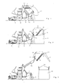
- the collecting machine is designed as a self-propelled mower, scarifier and sweeper. It has the frame 1, which is supported on the ground via the drive wheels 2 and the wheels 3. In the front region, the receiving device 4 is arranged on the frame 5 having the frame 1. The receiving device 4 receives the goods to be collected and conveys it via a transport device, not shown in the adjoining the housing 5 collecting container 6.
- the collecting container 6 has on its top the covered with the lid 7 covering the discharge opening 8.
- the cover 7 is articulated by means of the joints 9, which have a pivot axis extending transversely to the direction of travel, pivotable on the collecting container 6 in the front upper region.
- the collecting container 6 is fixed by means of a pivoting and lifting device 10 on the frame 1 of the collecting machine. For emptying the collecting container 6, this can be pivoted from the position shown in FIG. 1 into the emptying position shown in FIG. 2 by means of motor actuating elements, not shown in detail.
- 6 receiving devices 11 are arranged on the collecting container.
- This Receiving device 11 are formed as the receiving container 12 at a defined load releasing means.
- these receiving devices 11 are formed as resiliently loaded clamping elements.
- These clamping elements 11 are resiliently loaded by means of the spring 12 clamping bracket 13, as Fig. 4 shows.
- the spring 13 By means of a spring 13, the clamps 13 are pulled against the wall 14 of the receptacle 6 and the lid 7.
- Two clamping elements 11 are attached to the collecting container 6 and two clamping elements 11 on the cover 7.
- the receptacle 12 designed as a big bag has four carrying loops 15.
- Each carrying loop 15 is pushed behind the spring-loaded clamping bracket 13, as shown in FIG. 4.
- the collecting container 6 is pivoted from the position shown in FIG. 1 into the position shown in FIG. As a result, the lid 7 pivots.
- the opening of the big bag is kept open and the big bag 12 stands on the ground.
- the lifting device 10 which is arranged between the frame 1 and the collecting container 6, the big bag 12 can be completely in the opened and stretched position be brought, so that the entire good, which is located in the collecting container 6 can fall into the big bag 12.
- the carrying loops 14 of the big bag 12 are released from the clamping elements 11, since they are set so spring loaded that the resilient clamping action is not sufficient to lift the filled big bag 12, as shown. 3 shows.
- the clamps 13 the carrying straps 14 of the big bags 12 free.
- the big bag lets Thus, without the driver having to dismount, detach from the sump 6.
- the collecting container 6 is brought by pivoting and driving down the lifting device 10 from the collection position 6 shown in FIG. 3 shown in FIG. If the sump is refilled or should be emptied, the driver brings again designed as a big bag 12 receptacle on the clamps. 13, so that in the manner described above, the emptying of the collecting container 6 in the big bag 12 can be performed.
- the receiving device may also be formed as shown in FIG. 5 as elastically bendable hook elements 16. These hook elements 16 then bend when lifting when the big bag 12 is filled with the goods located in the collecting container 6 and emptied in the big bag Good, so that the carrying straps can freely slip out of the bent hook elements and thus free from the sump, we show the dashed lines positions 16 '.
Abstract
Description
Die Erfindung betrifft eine fahrbare Sammelmaschine gemäß des Oberbegriffes des Patentanspruches 1.The invention relates to a mobile collecting machine according to the preamble of
Eine derartige Sammelmaschine ist beispielsweise durch die
Der Erfindung liegt die Aufgabe zugrunde, ein einfaches Entleeren des sich im Sammelbehälter befindlichen Gutes in ein Aufnahmebehältnis zu ermöglichen.The invention has for its object to enable a simple emptying of the goods located in the collecting container in a receptacle.
Diese Aufgabe wird erfindungsgemäß durch die Merkmale des Kennzeichens des Patentanspruches 1 gelöst. Infolge dieser Maßnahmen ist es möglich, vor der Entleerungsöffnung des Sammelbehälters mittels der Aufnahmevorrichtung ein Aufnahmebehältnis anzuordnen, in welchem das sich im Sammelbehälter befindliche Gut geschüttet werden kann. Mittels der Aufnahmevorrichtung, an dem das Aufnahmebehältnis befestigt ist, wird das Aufnahmebehältnis in der richtigen Position zum Sammelbehälter gehalten, so dass das Gut aus dem Sammelbehälter überladen werden kann. Hierbei sind die Aufnahmevorrichtungen so ausgebildet, dass eine Überlastung des Sammelbehälters bzw. von Einrichtungen der Sammelmaschine, wie die Achslast etc. nicht eintreten kann. Denn bei einer definierten Belastung geben die Aufnahmevorrichtungen das Aufnahmebehältnis frei, so dass das Aufnahmebehältnis vom Sammelbehälter getrennt wird.This object is achieved by the features of the characterizing part of
Beim Umfüllen des Gutes aus dem Sammelbehälter in das Aufnahmebehältnis steht das Aufnahmebehältnis auf dem Boden und durch die Aufnahmevorrichtungen wird, wenn das Aufnahmebehältnis beispielsweise aus einem Sack besteht, in der richtigen Form und Position gehalten werden.When decanting the material from the collection container into the receptacle, the receptacle is on the floor and by the receiving devices, if the receptacle consists for example of a bag, be kept in the correct shape and position.
Damit die Aufnahmevorrichtung bei einer definierten Belastung des Aufnahmebehältnisses in einfacher Form freigeben können ist vorgesehen, dass die Mittel als federnd belastete Klemmelemente ausgebildet sind. Hierbei können die Klemmelemente federnd belastete Klemmbügel sein.So that the receiving device can release in a defined load of the receptacle in a simple form is provided that the means are designed as resiliently loaded clamping elements. Here, the clamping elements may be resiliently loaded clamping bracket.
Auch ist es möglich, die Mittel als elastisch umbiegbare Hakenelemente auszubilden. Hier kann dann das Aufnahmebehältnis aus den Hakenelementen heraus rutschen.It is also possible to form the means as elastically bendable hook elements. Here then the receptacle from the hook elements slip out.
Bei einem Sammelbehälter, der ein seine Entleerungsöffnung abdeckendes und zum Entleeren aufschwenkbares Abdeckelement aufweist, ist zur vorteilhaften Befestigung und richtigen Positionierung des Aufnahmebehälters vorgesehen, dass die Mittel an dem Abdeckelement in dem der Aufschwenkseite des Abdeckelementes benachbarten Bereich und an dem Sammelbehälter an dem der Aufschwenkseite des Abdeckelementes benachbarten Bereich angeordnet sind.In a collecting container having a covering its discharge opening and aufschwenkbares for emptying cover, is provided for advantageous attachment and correct positioning of the receptacle, that the means on the cover in the Aufschwenkseite of the cover adjacent area and on the collecting tank at the Aufschwenkseite of the Covering element adjacent area are arranged.
Das Sammelbehältnis lässt sich in einfacher Weise an dem Sammelbehälter und an dem Abdeckelement dadurch befestigen, dass an dem Sammelbehälter und an dem Abdeckelement jeweils zwei Mittel angeordnet sind.The collecting container can be attached in a simple manner to the collecting container and to the covering element, that in each case two means are arranged on the collecting container and on the cover.
Eine einfache Ausgestaltung des Aufnahmebehältnisses kann als Auffangsack oder als sog. Big bag vorgesehen sein.A simple embodiment of the receptacle can be provided as a collection bag or as so-called. Big bag.
Eine einfache Befestigung des Aufnahmebehältnisses an dem Sammelbehälter und/oder dem Abdeckelement lässt sich dadurch erreichen, dass das Aufnahmebehältnis Trageschlaufen aufweist, dass die Trageschlaufen von den Aufnahmevorrichtungen aufgenommen werden.A simple attachment of the receptacle to the collecting container and / or the cover can be achieved in that the receptacle has carrying straps that the straps are received by the recording devices.
Um in einfacher Weise das Sammelbehältnis in der richtigen Form in Position zu dem Sammelbehälter zu halten bzw. Sammelbehälter vom Aufnahmebehältnis zu trennen, lässt sich dadurch erreichen, dass der Sammelbehälter mittels einer Hebevorrichtung, mittels der der Sammelbehälter anhebbar ist, an dem Rahmen und/oder Gehäuse angeordnet ist.In order to easily hold the collecting container in the correct form in position to the collecting container or separate collecting container from the receptacle, can be achieved in that the collecting container by means of a lifting device by means of the collecting container can be raised on the frame and / or Housing is arranged.
Somit können durch Anheben des Sammelbehälters die Mittel das Aufnahmebehältnis oder die Trageschlaufen nach zumindest einer Teilumfüllung des Gutes aus dem Sammelbehälter in das Aufnahmebehältnis freigeben.Thus, by lifting the collecting container, the means can release the receptacle or the carrying loops after at least a partial transfer of the goods from the collecting container into the receptacle.
Zusammenfassend wird der Vorteil erreicht, das der Sammelbehälter der Sammelmaschine in einem als Big bag ähnlichen Sack ausgebildeten Aufnahmebehältnis zu entleeren, und ohne die Maschine zu überlasten und ein automatisches Aushängen des Aufnahmebehältnisses nach Beendigung des Entleerungsvorganges vom Fahrersitz aus zu ermöglichen. Dies lässt sich dadurch realisieren, dass die Schlaufen oder andere Teile des Aufnahmebehältnisses an eine z. B. in ihrer Klemmstärke einstellbare Halterung angeklemmt werden können. Im leeren und somit leichten Zustand wird das Aufnahmebehältnis offen gehalten. Ist das Aufnahmebehältnis gefüllt, was in bodennaher Position erfolgen muss, so dass die Unterseite des Aufnahmebehältnisses auf dem Boden aufsteht, wird die Öffnung des Behältnisses durch die beispielsweise als Klemmmittel ausgebildeten Mittels die Öffnung des Aufnahmebehältnisses offen gehalten. Wird der Sammelbehälter der Sammelmaschine dann angehoben, so sorgt das Gewicht des Sackes mit dem darin befindlichen überladenen Gut für ein selbständiges Lösen des Aufnahmebehältnisses aus den bei einer definierten Lastung freigegebenen Mitteln. Wird der Sammelbehälter in nicht bodennaher Position des Aufnahmebehältnisses überladen, so lösen sich die Schlaufen oder andere Teile des Aufnahmebehältnisses sofort auf den Mitteln, eine Überlastung der Achse Sammelmaschine wird verhindert.In summary, the advantage is achieved that emptying the collecting container of the collecting machine in a receptacle designed as a big bag similar receptacle, and without overloading the machine and to allow automatic detachment of the receptacle after completion of the emptying process from the driver's seat. This can be realized in that the loops or other parts of the receptacle to a z. B. adjustable clamp can be clamped in their clamping strength. In the empty and thus light condition becomes the Receptacle kept open. If the receptacle is filled, which must be done in the ground-level position, so that the underside of the receptacle stands up on the floor, the opening of the container is held open by the example designed as a clamping means means the opening of the receptacle. If the collecting container of the collecting machine is then raised, the weight of the bag with the overloaded material contained therein ensures an independent release of the receptacle from the means released at a defined load. If the collection container is overloaded in a non-ground-level position of the receptacle, so loosen the loops or other parts of the receptacle immediately on the means, overloading the axis collecting machine is prevented.
Weitere Einzelheiten der Erfindung sind der Beispielsbeschreibung und den Zeichnungen zu entnehmen. Hierbei zeigen
- Fig. 1
- die Sammelmaschine mit an dem Deckel und dem Sammelbehälter eingehängtem Aufnahmebehältniss vor dem Entleerungsvorgang in Seitenansicht.
- Fig. 2
- die Sammelmaschine mit in Entleerungsposition geschwenkten Sammelbehälter beim Überladevorgang in Seitenansicht,
- Fig. 3
- die Sammelmaschine mit angehobenem Sammelbehälter und gefülltem Aufnahmebehältnisse nach dem Entleerungsvorgang in Seitenansicht,
- Fig. 4
- das bei einer definierten Belastung frei gegebende und als Klemmmittel ausgebildete Mittel in Seitenansicht und vergrößertem Maßstab und
- Fig. 5
- eine weitere Aufnahmevorrichtung, die als elastisch umbiegbares Halteelement ausgebildet ist, in Seitenansicht.
- Fig. 1
- the collecting machine with hinged on the lid and the receptacle Aufnahmebehältniss before the emptying process in side view.
- Fig. 2
- the collecting machine with collecting container pivoted in emptying position during the transfer operation in side view,
- Fig. 3
- the collecting machine with raised collecting container and filled receptacles after the emptying process in side view,
- Fig. 4
- in a defined load freely issuing and trained as a clamping means in side view and on an enlarged scale and
- Fig. 5
- a further receiving device, which is designed as elastically bendable retaining element, in side view.
Die Sammelmaschine ist als selbstfahrendes Mäh-, Vertikutierund Kehrgerät ausgebildet. Sie weist den Rahmen 1 auf, der sich über die Antriebesräder 2 und die Laufräder 3 auf dem Boden abstützt. Im vorderen Bereich ist die Aufnahmevorrichtung 4 an dem das Gehäuse 5 aufweisenden Rahmen 1 angeordnet. Die Aufnahmevorrichtung 4 nimmt das aufzusammelnde Gut auf und fördert es über eine nicht dargestellte Transportvorrichtung in den sich an dem Gehäuse 5 anschließende Sammelbehälter 6. Der Sammelbehälter 6 weist auf seiner Oberseite die mit dem als Deckel ausgebildeten Abdeckelement 7 abgedeckte Entleerungsöffnung 8 auf. Der Deckel 7 ist mittels der Gelenken 9, die eine quer zur Fahrtrichtung verlaufende Schwenkachse aufweisen, an dem Sammelbehälter 6 im vorderen oberen Bereich aufschwenkbar angelenkt. Der Sammelbehälter 6 ist mittels einer Schwenkund Hebevorrichtung 10 am Rahmen 1 der Sammelmaschine befestigt. Zum Entleeren des Sammelbehälters 6 kann dieser aus den in Fig. 1 dargestellten Position in die in Fig. 2 dargestellte Entleerungsstellung mittels im Einzelnen nicht dargestellte motorischer Betätigungselemente verschwenkt werden.The collecting machine is designed as a self-propelled mower, scarifier and sweeper. It has the
Um das sich in dem Sammelbehälter 6 befindliche aufgesammelte Gut in ein beispielsweise als Big bag ausgebildetes Aufnahmebehältnis zu entleeren, sind an dem Sammelbehälter 6 Aufnahmevorrichtungen 11 angeordnet. Dieser Aufnahmevorrichtung 11 sind als das das Aufnahmebehältnis 12 bei einer definierten Belastung freigebende Mittel ausgebildet. Gemäß der Ausführungsbeispiele nach den Fig. 1 bis 4 sind diese Aufnahmevorrichtungen 11 als federnd belastete Klemmelemente ausgebildet. Diese Klemmelemente 11 sind federnd mittels der Feder 12 belastete Klemmbügel 13, wie Fig. 4 zeigt. Mittels einer Feder 13 werden die Klemmbügel 13 gegen die Wand 14 des Aufnahmebehältnisses 6 bzw. des Deckels 7 gezogen. Zwei Klemmelemente 11 sind am Sammelbehälter 6 und zwei Klemmelemente 11 an dem Deckel 7 befestigt. Im Ausführungsbeispiel weist das als Big bag ausgebildete Aufnahmebehältnis 12 vier Trageschlaufen 15 auf. Jede Trageschlaufe 15 wird hinter den federbelasteten Klemmbügel 13 geschoben, wie Fig. 4 zeigt. Um das sich im Sammelbehälter 6 befindliche aufgesammelte Gut über die Entleerungsöffnung in den Big bag 12 zu entleeren, wird der Sammelbehälter 6 aus der in Fig. 1 dargestellten Position in die in Fig. 2 dargestellte Position verschwenkt. Hierdurch schwenkt der Deckel 7 auf. Gleichzeitig wird die Öffnung des Big bags offen gehalten und der Big bag 12 steht auf dem Boden auf. Das sich im Sammelbehälter befindliche Gut fällt über die Entleerungsöffnung 8 in den Big bag 12. Durch Anheben des Sammelbehälters 6 mittels der Hebevorrichtung 10, die zwischen dem Rahmen 1 und dem Sammelbehälter 6 angeordnet ist, kann der Big bag 12 ganz in geöffneter und gestreckter Lage gebracht werden, so dass das gesamte Gut, welches sich im Sammelbehälter 6 befindet in den Big bag 12 fallen kann. Durch weiteres nach oben bewegen des Sammelbehälters 6 über die Hebevorrichtung 10 lösen sich die Trageschlaufen 14 des Big bag 12 aus den Klemmelementen 11, da sie derart federbelastet eingestellt sind, dass die federnde Klemmwirkung nicht ausreicht, den gefüllten Big bag 12 anzuheben, wie Fig. 3 zeigt. Somit geben die Klemmbügel 13 die Trageschlaufen 14 des Big bags 12 frei. Der Big bag lässt sich also, ohne dass der Fahrer absteigen muss, von dem Sammelbehälter 6 lösen. Anschließend wird der Sammelbehälter 6 durch Verschwenken und nach unten fahren der Hebevorrichtung 10 aus der in Fig. 3 dargestellten Position in Fig. 1 dargestellte Sammelposition 6 gebracht. Wenn der Sammelbehälter wieder gefüllt ist bzw. entleert werden soll, bringt der Fahrer erneut einen als Big bag 12 ausgebildetes Aufnahmebehältnisses an den Klemmbügeln. 13 an, so dass in vorbeschriebener Weise das Entleeren des Sammelbehälters 6 in den Big bag 12 durchgeführt werden kann.In order to empty the accumulated in the collecting
An Stelle die Aufnahmevorrichtung als Klemmelemente 11 oder Klemmbügel 12 auszubilden, können sie auch entsprechend der Fig. 5 als elastisch umbiegbare Hakenelemente 16 ausgebildet sein. Diese Hakenelemente 16 biegen sich dann beim Anheben, wenn der Big bag 12 mit dem sich in dem Sammelbehälter 6 befundenen und in dem Big bag entleerten Gut gefüllt ist um, so dass die Trageschlaufen frei aus den umbiegbären Hakenelementen herausrutschen und so vom Sammelbehälter freikommen können, wir die gestrichelt dargestellte Positione 16' zeigt.Instead of forming the receiving device as clamping
Claims (11)
Applications Claiming Priority (1)
| Application Number | Priority Date | Filing Date | Title |
|---|---|---|---|
| DE200610035144 DE102006035144A1 (en) | 2006-07-29 | 2006-07-29 | Mobile collecting machine |
Publications (1)
| Publication Number | Publication Date |
|---|---|
| EP1882406A1 true EP1882406A1 (en) | 2008-01-30 |
Family
ID=38481536
Family Applications (1)
| Application Number | Title | Priority Date | Filing Date |
|---|---|---|---|
| EP07014295A Withdrawn EP1882406A1 (en) | 2006-07-29 | 2007-07-20 | Moveable collecting machine |
Country Status (2)
| Country | Link |
|---|---|
| EP (1) | EP1882406A1 (en) |
| DE (1) | DE102006035144A1 (en) |
Cited By (4)
| Publication number | Priority date | Publication date | Assignee | Title |
|---|---|---|---|---|
| WO2013044930A2 (en) * | 2011-09-26 | 2013-04-04 | Fiber- K Industrial S.A. | Bagging machine suitable for all types of dry and wet grain |
| US9622410B2 (en) * | 2014-03-06 | 2017-04-18 | Deere & Company | Material collection parking system |
| US20190320583A1 (en) * | 2018-04-24 | 2019-10-24 | Kubota Corporation | Grass collecting assembly for grass mower |
| WO2022048879A1 (en) * | 2020-09-01 | 2022-03-10 | Alfred Kärcher SE & Co. KG | Automotive sweeper and method for producing a sweeper |
Families Citing this family (1)
| Publication number | Priority date | Publication date | Assignee | Title |
|---|---|---|---|---|
| DE102014000753A1 (en) * | 2014-01-21 | 2015-07-23 | Manfred Renschler | Clippings grass catcher for lawn mower / tractors |
Citations (4)
| Publication number | Priority date | Publication date | Assignee | Title |
|---|---|---|---|---|
| WO1986000003A1 (en) * | 1984-06-08 | 1986-01-03 | Maskinfabriken Taarup A/S | A method and a loading or transport vehicle for the packaging of crop |
| DE4232541A1 (en) * | 1991-10-01 | 1993-04-08 | Paul M Gamaldi | LIFTING AND TILTING DEVICE FOR EMPTYING A CONTAINER |
| EP0610062A1 (en) * | 1993-02-01 | 1994-08-10 | Electrolux Outdoor Products Limited | Improvements in and relating to collection devices |
| EP0692576A1 (en) * | 1994-07-15 | 1996-01-17 | R.C.M. S.p.A. | Improved unloading device for the hopper of a mechanical sweeper for large surfaces |
-
2006
- 2006-07-29 DE DE200610035144 patent/DE102006035144A1/en not_active Withdrawn
-
2007
- 2007-07-20 EP EP07014295A patent/EP1882406A1/en not_active Withdrawn
Patent Citations (4)
| Publication number | Priority date | Publication date | Assignee | Title |
|---|---|---|---|---|
| WO1986000003A1 (en) * | 1984-06-08 | 1986-01-03 | Maskinfabriken Taarup A/S | A method and a loading or transport vehicle for the packaging of crop |
| DE4232541A1 (en) * | 1991-10-01 | 1993-04-08 | Paul M Gamaldi | LIFTING AND TILTING DEVICE FOR EMPTYING A CONTAINER |
| EP0610062A1 (en) * | 1993-02-01 | 1994-08-10 | Electrolux Outdoor Products Limited | Improvements in and relating to collection devices |
| EP0692576A1 (en) * | 1994-07-15 | 1996-01-17 | R.C.M. S.p.A. | Improved unloading device for the hopper of a mechanical sweeper for large surfaces |
Cited By (7)
| Publication number | Priority date | Publication date | Assignee | Title |
|---|---|---|---|---|
| WO2013044930A2 (en) * | 2011-09-26 | 2013-04-04 | Fiber- K Industrial S.A. | Bagging machine suitable for all types of dry and wet grain |
| US20140230961A1 (en) * | 2011-09-26 | 2014-08-21 | Fiber-K Industrial S.A. | Bagging machine suitable for all types of dry and wet grain |
| WO2013044930A3 (en) * | 2011-09-26 | 2014-11-27 | Fiber- K Industrial S.A. | Bagging machine suitable for all types of dry and wet grain |
| US9446866B2 (en) | 2011-09-26 | 2016-09-20 | Fiber-K Industrial S.A. | Bagging machine suitable for all types of dry and wet grain |
| US9622410B2 (en) * | 2014-03-06 | 2017-04-18 | Deere & Company | Material collection parking system |
| US20190320583A1 (en) * | 2018-04-24 | 2019-10-24 | Kubota Corporation | Grass collecting assembly for grass mower |
| WO2022048879A1 (en) * | 2020-09-01 | 2022-03-10 | Alfred Kärcher SE & Co. KG | Automotive sweeper and method for producing a sweeper |
Also Published As
| Publication number | Publication date |
|---|---|
| DE102006035144A1 (en) | 2008-01-31 |
Similar Documents
| Publication | Publication Date | Title |
|---|---|---|
| DE2339584A1 (en) | Grass and foliage suction machine - has wheeled, towed or motor-driven chassis with fan connected by pipe to collector | |
| EP1882406A1 (en) | Moveable collecting machine | |
| EP1391149A1 (en) | Cover for a vehicle with open topped container | |
| DE2647814A1 (en) | ROOT HARVESTING MACHINE | |
| DE202005013271U1 (en) | Collecting wheelbarrow has trough-like container with opening facing forwards and closable by restraining flap in lower part aligned perpendicular to travel direction to retain collected items | |
| DE1482245A1 (en) | Beet harvester for self-loading wagons | |
| DE102006034436A1 (en) | Mobile collecting machine e.g. mowing device, has collecting bag removably attached to collecting frame, and collector hung with rolled periphery region over circular region of collecting frame | |
| WO1995028341A1 (en) | Waste collecting system | |
| DE4318807A1 (en) | Process and apparatuses for sorting seeds | |
| DE202004009335U1 (en) | Self-propelled vehicle for collecting horse dung has endless belt mounted at the front, above flat panel, belt being fitted with transverse rows of flexible fingers which push dung into tank at rear of vehicle | |
| DE102019112257A1 (en) | Device for mucking up yards and meadows | |
| DE817972C (en) | Potato harvester | |
| DE2708158C3 (en) | Device for loading and transporting fodder beet | |
| DE19952381C2 (en) | Fruit picking facility | |
| DE203614C (en) | ||
| DE4101634C2 (en) | ||
| DE1782469C3 (en) | Potato collecting harvester with a tiltable collecting bunker | |
| DE636108C (en) | Garbage collector for binding mower | |
| DE2633863A1 (en) | Beet harvester and transporter - has swinging container and side platform with spring loaded swinging arm engaging stop under platform | |
| DE453482C (en) | Loader for hay and like | |
| DE679921C (en) | Machine for loosening, rearranging, sifting or transferring bulk goods into bags | |
| DE2307945C3 (en) | Mower with a housing accommodating a mower device | |
| DE815862C (en) | Potato harvester | |
| DE7328581U (en) | LAWN AND LEAF SUCTION DEVICE | |
| DE202019102635U1 (en) | Device for clearing farms and meadows |
Legal Events
| Date | Code | Title | Description |
|---|---|---|---|
| PUAI | Public reference made under article 153(3) epc to a published international application that has entered the european phase |
Free format text: ORIGINAL CODE: 0009012 |
|
| AK | Designated contracting states |
Kind code of ref document: A1 Designated state(s): AT BE BG CH CY CZ DE DK EE ES FI FR GB GR HU IE IS IT LI LT LU LV MC MT NL PL PT RO SE SI SK TR |
|
| AX | Request for extension of the european patent |
Extension state: AL BA HR MK YU |
|
| 17P | Request for examination filed |
Effective date: 20080730 |
|
| 17Q | First examination report despatched |
Effective date: 20080828 |
|
| AKX | Designation fees paid |
Designated state(s): AT BE BG CH CY CZ DE DK EE ES FI FR GB GR HU IE IS IT LI LT LU LV MC MT NL PL PT RO SE SI SK TR |
|
| STAA | Information on the status of an ep patent application or granted ep patent |
Free format text: STATUS: THE APPLICATION IS DEEMED TO BE WITHDRAWN |
|
| 18D | Application deemed to be withdrawn |
Effective date: 20090108 |