EP1881173A1 - Diffusor for internal combustion engine and engine with such a diffusor - Google Patents
Diffusor for internal combustion engine and engine with such a diffusor Download PDFInfo
- Publication number
- EP1881173A1 EP1881173A1 EP07109431A EP07109431A EP1881173A1 EP 1881173 A1 EP1881173 A1 EP 1881173A1 EP 07109431 A EP07109431 A EP 07109431A EP 07109431 A EP07109431 A EP 07109431A EP 1881173 A1 EP1881173 A1 EP 1881173A1
- Authority
- EP
- European Patent Office
- Prior art keywords
- diffuser
- insert
- housing
- longitudinal axis
- opening angle
- Prior art date
- Legal status (The legal status is an assumption and is not a legal conclusion. Google has not performed a legal analysis and makes no representation as to the accuracy of the status listed.)
- Granted
Links
- 238000002485 combustion reaction Methods 0.000 title claims abstract description 37
- 230000001788 irregular Effects 0.000 claims description 2
- 239000007789 gas Substances 0.000 description 36
- 230000002000 scavenging effect Effects 0.000 description 8
- 238000006243 chemical reaction Methods 0.000 description 2
- 230000001419 dependent effect Effects 0.000 description 2
- 238000011010 flushing procedure Methods 0.000 description 2
- 238000000926 separation method Methods 0.000 description 2
- 239000013598 vector Substances 0.000 description 2
- 230000005540 biological transmission Effects 0.000 description 1
- 230000015572 biosynthetic process Effects 0.000 description 1
- 238000010276 construction Methods 0.000 description 1
- 230000006866 deterioration Effects 0.000 description 1
- 230000009931 harmful effect Effects 0.000 description 1
- 238000009434 installation Methods 0.000 description 1
- 230000003993 interaction Effects 0.000 description 1
- 238000010926 purge Methods 0.000 description 1
- 238000004904 shortening Methods 0.000 description 1
- XLYOFNOQVPJJNP-UHFFFAOYSA-N water Substances O XLYOFNOQVPJJNP-UHFFFAOYSA-N 0.000 description 1
- 238000004804 winding Methods 0.000 description 1
Images


Classifications
-
- F—MECHANICAL ENGINEERING; LIGHTING; HEATING; WEAPONS; BLASTING
- F02—COMBUSTION ENGINES; HOT-GAS OR COMBUSTION-PRODUCT ENGINE PLANTS
- F02B—INTERNAL-COMBUSTION PISTON ENGINES; COMBUSTION ENGINES IN GENERAL
- F02B37/00—Engines characterised by provision of pumps driven at least for part of the time by exhaust
- F02B37/02—Gas passages between engine outlet and pump drive, e.g. reservoirs
-
- F—MECHANICAL ENGINEERING; LIGHTING; HEATING; WEAPONS; BLASTING
- F02—COMBUSTION ENGINES; HOT-GAS OR COMBUSTION-PRODUCT ENGINE PLANTS
- F02B—INTERNAL-COMBUSTION PISTON ENGINES; COMBUSTION ENGINES IN GENERAL
- F02B33/00—Engines characterised by provision of pumps for charging or scavenging
- F02B33/44—Passages conducting the charge from the pump to the engine inlet, e.g. reservoirs
-
- F—MECHANICAL ENGINEERING; LIGHTING; HEATING; WEAPONS; BLASTING
- F02—COMBUSTION ENGINES; HOT-GAS OR COMBUSTION-PRODUCT ENGINE PLANTS
- F02B—INTERNAL-COMBUSTION PISTON ENGINES; COMBUSTION ENGINES IN GENERAL
- F02B29/00—Engines characterised by provision for charging or scavenging not provided for in groups F02B25/00, F02B27/00 or F02B33/00 - F02B39/00; Details thereof
- F02B29/04—Cooling of air intake supply
-
- F—MECHANICAL ENGINEERING; LIGHTING; HEATING; WEAPONS; BLASTING
- F02—COMBUSTION ENGINES; HOT-GAS OR COMBUSTION-PRODUCT ENGINE PLANTS
- F02B—INTERNAL-COMBUSTION PISTON ENGINES; COMBUSTION ENGINES IN GENERAL
- F02B75/00—Other engines
- F02B75/02—Engines characterised by their cycles, e.g. six-stroke
- F02B2075/022—Engines characterised by their cycles, e.g. six-stroke having less than six strokes per cycle
- F02B2075/025—Engines characterised by their cycles, e.g. six-stroke having less than six strokes per cycle two
-
- F—MECHANICAL ENGINEERING; LIGHTING; HEATING; WEAPONS; BLASTING
- F02—COMBUSTION ENGINES; HOT-GAS OR COMBUSTION-PRODUCT ENGINE PLANTS
- F02B—INTERNAL-COMBUSTION PISTON ENGINES; COMBUSTION ENGINES IN GENERAL
- F02B25/00—Engines characterised by using fresh charge for scavenging cylinders
- F02B25/02—Engines characterised by using fresh charge for scavenging cylinders using unidirectional scavenging
- F02B25/04—Engines having ports both in cylinder head and in cylinder wall near bottom of piston stroke
-
- F—MECHANICAL ENGINEERING; LIGHTING; HEATING; WEAPONS; BLASTING
- F02—COMBUSTION ENGINES; HOT-GAS OR COMBUSTION-PRODUCT ENGINE PLANTS
- F02B—INTERNAL-COMBUSTION PISTON ENGINES; COMBUSTION ENGINES IN GENERAL
- F02B37/00—Engines characterised by provision of pumps driven at least for part of the time by exhaust
-
- F—MECHANICAL ENGINEERING; LIGHTING; HEATING; WEAPONS; BLASTING
- F02—COMBUSTION ENGINES; HOT-GAS OR COMBUSTION-PRODUCT ENGINE PLANTS
- F02F—CYLINDERS, PISTONS OR CASINGS, FOR COMBUSTION ENGINES; ARRANGEMENTS OF SEALINGS IN COMBUSTION ENGINES
- F02F7/00—Casings, e.g. crankcases or frames
- F02F2007/0097—Casings, e.g. crankcases or frames for large diesel engines
-
- F—MECHANICAL ENGINEERING; LIGHTING; HEATING; WEAPONS; BLASTING
- F02—COMBUSTION ENGINES; HOT-GAS OR COMBUSTION-PRODUCT ENGINE PLANTS
- F02M—SUPPLYING COMBUSTION ENGINES IN GENERAL WITH COMBUSTIBLE MIXTURES OR CONSTITUENTS THEREOF
- F02M35/00—Combustion-air cleaners, air intakes, intake silencers, or induction systems specially adapted for, or arranged on, internal-combustion engines
- F02M35/10—Air intakes; Induction systems
- F02M35/10242—Devices or means connected to or integrated into air intakes; Air intakes combined with other engine or vehicle parts
- F02M35/10262—Flow guides, obstructions, deflectors or the like
Definitions
- the invention relates to a multi-diffuser for a reciprocating internal combustion engine, in particular for a two-stroke large diesel engine, and a reciprocating internal combustion engine with an inventive multi-diffuser according to the preamble of the independent claims.
- the fresh air is introduced by a Aufladeoli, which is usually designed as an exhaust gas turbocharger, under increased pressure in the combustion chamber of a cylinder after a combustion cycle.
- a part of the thermal energy of the exhaust gases can be exploited, leaving the combustion chamber of the cylinder after the combustion cycle.
- the hot exhaust gases are supplied by opening an exhaust valve from the combustion chamber of the cylinder of nieladeenstein.
- the charging group consists essentially of a turbine, which passes through the hot exhaust gases entering under pressure in the charging group is driven. The turbine in turn drives an impeller, whereby fresh air is sucked in and compressed.
- the turbine with impeller as a compressor an arrangement which is often referred to simply as a turbocharger and especially, but not only, designed in the case of two-stroke large diesel engines as a centrifugal compressor, a so-called diffuser, a charge air cooler with a water separator and an inlet receiver downstream of where from the compressed fresh air, also referred to as charge air or scavenging air, is finally fed into the individual combustion chambers of the cylinder of the large diesel engine.
- the use of such a charging group can thus increase the supply of fresh air and increase the efficiency of the combustion process in the combustion chamber of the cylinder.
- the supply of air takes place at different points on the cylinder.
- the air is introduced into the combustion chamber of the cylinder via scavenging slots which are arranged in the running surface in the lower region of the cylinder.
- the charge air is usually introduced via one or more intake valves, which are arranged in the cylinder cover into the combustion chamber of the cylinder.
- two-stroke engines are quite well known, which are equipped instead of scavenging slots in the lower part of the cylinder with intake valves in the cylinder cover.
- a diffuser is essentially a funnel-shaped extension of a flow channel. It generally serves to delay, that is, to reduce the flow velocity of the flow, so that according to the known law of Bernoulli an increase in pressure is achieved.
- the double opening angle of 2 ⁇ of the diffuser should be about 16 ° 8 ° do not exceed.
- the opening angle that forms a diffuser wall with a longitudinal axis of the diffuser should be as small as possible about 8 °, preferably less than 4 °. It is known, downstream subsonic fans in particular with the use of centrifugal fans, centrifugal pumps, jet pumps, centrifugal compressors, etc., where it is necessary to recover energy through effective conversion of kinetic energy in pressure.
- the above-mentioned limitation of the opening angle has some significant disadvantages.
- a certain size can not be exceeded, if a predetermined efficiency is to be achieved. That is, the diffuser must have a certain minimum length depending on the application and the efficiency to be achieved, which of course is very disadvantageous in confined spaces, e.g. when there is not enough space between the turbocharger and intercooler connected to the diffuser in a two-stroke large diesel engine.
- a multidiffuser is understood by the person skilled in the art to be the concentric nesting of several diffusers, thus forming the multi-diffuser. That means it will be two or a plurality of hollow bodies, for example in the form of different sized cones with the same or different opening angles, concentrically nested.
- the object of the invention is therefore to propose an improved diffuser for a reciprocating internal combustion engine, in particular two-stroke large diesel engine, which has a significantly reduced overall length compared to the known diffusers, preferably additionally has a higher efficiency than the diffusers previously used in the prior art or at the same length as the known diffusers has a significantly improved efficiency.
- Another object of the invention is to bring a reciprocating internal combustion engine, in particular two-stroke large diesel engine with an improved diffuser in proposal.
- the invention thus relates to a multi-diffuser for a reciprocating internal combustion engine, in particular two-stroke large diesel engine, wherein the multi-diffuser comprises a diffuser housing extending from a diffuser inlet to a diffuser exit along a longitudinal axis with a diffuser insert disposed in the interior of the diffuser housing.
- the diffuser inlet can be connected to an outlet of an exhaust gas turbocharger and the diffuser outlet to a charge air cooler of the reciprocating internal combustion engine, so that in the operating state of the reciprocating internal combustion engine from the exhaust gas turbocharger fresh air via the multi-diffuser in the intercooler can be introduced.
- the multi-diffuser is designed asymmetrically with respect to the longitudinal axis.
- the exhaust gas turbocharger is charging side, e.g. designed as a radial compressor, whose basic structure and operation has long been well known to those skilled in the art, it has been found that at the output of the compressor of the exhaust gas turbocharger, for example in the region of an inner radius at the inner edge of the cross-sectional area of the exhaust gas turbocharger output, the speed and / or direction of the outflowing gas is significantly different than at the outer edge of the exit.
- the speed and / or direction of the outflowing gas is significantly different than at the outer edge of the exit.
- the multi-diffuser of the present invention is designed asymmetrically with respect to its longitudinal axis.
- the construction of the multi-diffuser according to the invention is adapted in the specific case to the velocity profile which the exhaust-gas turbocharger delivers at its outlet and thus at the diffuser inlet.
- At least one first diffuser insert is designed as a hollow body which widens in the direction of the diffuser exit, in particular in the form of a straight or not straight cone.
- this is preferably formed asymmetrically with respect to the longitudinal axis of the diffuser housing in the diffuser housing.
- the diffuser insert itself is not a circle symmetrical cone and / or a longitudinal axis of the diffuser insert is not parallel to the longitudinal axis of the diffuser housing and / or is not identical to this.
- the diffuser housing itself is not symmetrical.
- a diffuser insert designated as a second diffuser insert may well be provided which is designed as a compact body which widens in the direction of the diffuser exit, in particular in the form of a straight or not straight compact cone.
- the fresh air can thus not flow through the second diffuser insert, but only flows past the outer surface.
- the symmetry adjustment of the multi-diffuser to the velocity profile of the incoming fresh air can also be achieved by the installation of a third diffuser insert, which is designed in the form of a baffle, which is therefore not a compact cone or cone open on the input side and output side.
- a housing cross-section of the diffuser housing and / or an insert cross-section of the diffuser insert is designed as a cross-sectional area which increases in the direction of the diffuser exit.
- the housing cross-section and / or the insert cross-section can e.g. be formed circular and / or elliptical and / or in the form of a regular or irregular polygon, in particular in the form of a triangle or a quadrangle or a pentagon.
- the diffuser housing and / or the diffuser insert preferably extends at a constant opening angle and / or continuously changing opening angle and / or under a discontinuously changing opening angle with respect to the longitudinal axis of the multi-diffuser.
- the constant opening angle and / or the constantly changing opening angle and / or the discontinuously changing opening angle may be a function of a polar angle measured perpendicular to the longitudinal axis.
- At least one diffuser insert and / or the diffuser housing is arranged asymmetrically with respect to the longitudinal axis of the diffuser housing.
- the diffuser housing and / or the diffuser insert may comprise a guide element, in particular a spiral-like guide element, in particular an arrangement with a guide vane, wherein the guide element is preferably arranged and configured such that a circumferential flow of can be deflected in the operating state from the exhaust gas turbocharger fresh air, in particular in an axial flow is deflected.
- the necessary symmetry adjustment can also be accomplished by extending the multi-diffuser from the diffuser inlet to the diffuser exit as a curved multi-diffuser along a curved longitudinal axis.
- the invention relates to a reciprocating internal combustion engine, in particular two-stroke large diesel engine with a multi-diffuser as described above or below with reference to the drawing.
- Fig. 1 shows a schematic representation to explain the interaction of the different components of the basic structure of an exhaust gas turbocharger system of a large diesel engine, which is designed as a two-stroke large diesel engine with longitudinal flush and equipped with an inventive multi-diffuser, which is hereinafter referred to collectively by the reference numeral 1 ,
- the large diesel engine usually comprises a plurality of cylinders 1000 with an exhaust valve 1001 arranged in a cylinder cover, in which cylinder 1000 a piston 1002 between a bottom dead center UT and a top dead center OT is arranged back and forth along a running surface.
- the cylinder 1000 with cylinder cover and the piston 1002 limit in known manner a combustion chamber of the cylinder 1000.
- several purge air openings 1003 are provided, which are designed as flushing slots 1003. Depending on the position of the piston 1002, the flushing slots 1003 are covered or released by this. Due to the scavenging air openings 1003, the fresh air 9 designated as scavenging air 9 can flow into the combustion chamber of the cylinder 1000.
- the exhaust gases 1004 formed during the combustion flow through an exhaust pipe 1005, which adjoins the exhaust valve 1001, into an exhaust gas turbocharger 7.
- the exhaust gas turbocharger 7 comprises, as essential components in a manner known per se, a compressor 71 with compressor impeller 711 for compressing air 9, and a turbine 72 with a turbine impeller 721 for driving the compressor impeller 711, which is operatively connected to the turbine impeller 721 by a shaft in a known manner connected is.
- the turbine 72 and the compressor 71 are arranged in a housing and form an exhaust-gas turbocharger 7, which in the present case is designed as a radial compressor 72 on the compressor side.
- the turbine 72 is driven in a known manner by the incoming hot exhaust gases 1004 from the combustion chamber of the cylinder 1000.
- fresh air 9 is sucked in through the compressor impeller 711 via an intake manifold and compressed in the exhaust gas turbocharger 7. From the exhaust gas turbocharger 7, the compressed fresh air 9 passes through a downstream multidiffusor 1 and a charge air cooler 8 via a pressure line into an inlet receiver 1006, from which the compressed fresh air 9 finally as scavenging air 9 through the scavenging slots 1003 under increased pressure in the combustion chamber of the cylinder 1000 arrives.
- Fig. 2 constructed as a centrifugal compressor exhaust gas turbocharger 7 is shown in somewhat greater detail.
- Radial compressors are known per se. These are compressors with an impeller flow, which have a radial velocity component except for the circumferential component for working transmission.
- the air is thus compressed by an impeller in the centrifugal compressor and conveyed at a certain speed V via the outlet 6 of the exhaust gas turbocharger 7 via the diffuser inlet 2 into the diffuser 1.
- the velocity V of the exiting fresh air 9 is dependent on the cross-sectional coordinate X and thus on the cross-sectional area 400 over a certain cross-sectional coordinate X over the insert cross section 500 of the output 6 of the exhaust gas turbocharger 7, and thus over the cross-sectional coordinate X over the housing cross-section 400.
- 500 not constant. That is, the velocities V of the fresh air 9 entering the multi-diffuser 1 from the exhaust-gas turbocharger 7 at a certain coordinate X obeys a velocity profile P which is a function of at least one coordinate X of the cross-sectional area 400, 500.
- This asymmetry in the velocity profile P of the fresh air 9 emerging from the exhaust-gas turbocharger 7 is taken into account by the asymmetrical design of the multi-diffuser 1 according to the invention, as is illustrated schematically in FIG. 3, for example.
- fresh air 9 is introduced from the exhaust-gas turbocharger 7 via the diffuser inlet 2 into a multi-diffuser 1 according to the invention.
- the velocity of the incoming fresh air 9 is reduced in a manner known per se, whereby according to the Benoulli law an increase in pressure of the fresh air 9 is achieved, which thus enters the charge air cooler 8 under increased pressure.
- the diffuser housing 4 like the diffuser insert 51, is asymmetrical with respect to FIG formed the longitudinal axis L of the multi-diffuser 1, whereby the asymmetric shape of the velocity profile P of the velocity distribution of the incoming fresh air 9 is optimally taken into account, so that in the inventive multi-diffuser 1 a high Efficiency can be achieved because the flow of fresh air 9 in the multi-diffuser 1 does not rupture, although the multi-diffuser 1 of Fig. 3 has a large opening angle and has a relatively short length.
- FIG. 4 shows a second exemplary embodiment of a multi-diffuser according to the invention according to FIG. 3 with a compact diffuser insert 5, 52.
- the arrangement shown in Fig. 4 corresponds substantially to the already described in detail arrangement of Fig. 3, wherein in Fig. 4, the diffuser insert 5, 52 but no expanding hollow body 51 in the form of a non-straight cone 51, as in Fig. 3rd but is a compact body 52 expanding toward the diffuser exit 3, which is configured in the form of a non-straight compact cone 52 so that the fresh air 9 can only flow around the compact cone 52 outside and not through the compact cone 52 therethrough.
- Whether a compact diffuser insert 52 or a hollow diffuser insert 51 is used depends inter alia on the specific shape of the velocity profile P of the velocity distribution of the incoming fresh air 9 in the multi-diffuser 1 and / or by other boundary conditions, such as the special design of the exhaust gas turbocharger 7 and / or the intercooler 8 and / or by other boundary conditions, such as the requirements that are to be made to size and shape of the multi-diffuser 1 itself determined.
- FIG. 5 shows a cross section through a multi-diffuser 1 with two asymmetrically arranged diffuser inserts 5.
- the diffuser housing 4 of the multi-diffuser 1 is formed asymmetrically with respect to the longitudinal axis L of the multi-diffuser 1 even in the form of an ellipse.
- the two diffuser inserts 5, 51 which in the exemplary embodiment of FIG. 5 are designed as hollow straight cones 5, 51 widening in the direction of the diffuser exit 3, which is not explicitly illustrated in FIG. 5, arranged asymmetrically with respect to the longitudinal axis L of Mutidiffusors 1 in the diffuser housing 4.
- FIG. 6 shows a cross section through a further exemplary embodiment of a multi-diffuser 1 with two asymmetrically designed diffuser inserts 5.
- the diffuser housing 4 is designed in the form of an ellipse, wherein the two diffuser inserts 5 are formed as hollow elliptical diffuser inserts 51. That is, the asymmetry of the multi-diffuser 1 with respect to the longitudinal axis L is established by the asymmetrical shape of the diffuser housing 4 and diffuser inserts 5, 51.
- a wall of the diffuser insert 5 can also be perforated, that is to say provided with bores or openings, so that the flow in the multi-diffuser 1 can be advantageously influenced in a suitable manner, depending on the geometry and / or velocity profile P of the incoming fresh air 9 is.
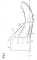
- Fig. 7 is a longitudinal section through a multi-diffuser 1 with continuously changing opening angle ⁇ 2 of the diffuser housing 4 is shown, wherein Fig. 8 shows the embodiment of Fig. 7 again in a perspective view.
- the multi-diffuser 1 according to FIG. 7 and FIG. 8 has exactly one diffuser insert 5, which is designed as a hollow cone 51 extending in the direction of the diffuser outlet 3. For reasons of clarity, only the diffuser housing 4 is shown in FIG. 8, and the diffuser insert 5, 51 is not visible.
- FIG. 7 clearly shows how the opening winding ⁇ 2 of the diffuser housing 4 changes continuously in the direction of the longitudinal axis L, by the opening angle ⁇ 2 from the diffuser inlet 2 to the diffuser outlet 3 is steadily smaller, while the opening angle ⁇ 1 of the diffuser insert 5, 51 remains constant along the longitudinal axis L.
- the constantly changing opening angle ⁇ 2 is a function of a polar angle ⁇ measured perpendicular to the longitudinal axis L, as a result of which inter alia the asymmetry of the multi-diffuser 1 according to the invention is determined.
- Fig. 7 and Fig. 8 is made.
- a further embodiment of the present invention is shown, wherein the diffuser insert 5 of the multi-diffuser 1 has a curved longitudinal axis L, whereby the asymmetry in the profile P of the velocity distribution of the fresh air 9 flowing into the multidiffuser 1 also advantageous for increasing the efficiency of can take into account multi-diffuser 1 according to the invention.
- FIGS. 10 and 11 show two exemplary embodiments of a multi-diffuser 1 according to the invention with baffles 5, 53.
- the diffuser insert 5, 53 of the multi-diffusers 1 according to FIGS. 10 and 11 are no hollow bodies extending in the direction of the diffuser exit 3 5, 51, but individual baffles 53, which are provided with respect to the longitudinal axis L asymmetrically in the diffuser housing 4 of the multi-diffuser 1.
- FIG. 12 shows a cross-section of a muti-diffuser 1 according to the invention with a spiral guide element 10, wherein the helical guide element 10 is arranged and configured in such a way that a circumferential flow of the fresh air 9 exiting from the exhaust-gas turbocharger 7 in the operating state can be deflected into an axial flow.
- FIG. 13 shows a perspective view of another exemplary embodiment of a multi-diffuser 1 according to the invention with guide elements 10, wherein the guide elements 10 likewise deflect the incoming fresh air 9 in an advantageous manner, and e.g. As schematically indicated in FIG. 13, a velocity component of the incoming fresh air 9 running in the circumferential direction of the multidiffuser 1 is converted into an axial component, so that the fresh air 9 flowing out of the multidiffuser 1 has essentially only one axial velocity component.
- FIG. 13 shows a perspective view of another exemplary embodiment of a multi-diffuser 1 according to the invention with guide elements 10, wherein the guide elements 10 likewise deflect the incoming fresh air 9 in an advantageous manner, and e.g. As schematically indicated in FIG. 13, a velocity component of the incoming fresh air 9 running in the circumferential direction of the multidiffuser 1 is converted into an axial component, so that the fresh air 9 flowing out of the multidiffuser 1 has essentially only one axial velocity component.
- FIG. 13 shows
- the guide elements 10 also serve to fasten the diffuser insert 5 in the diffuser housing 4 or to stabilize the diffuser insert 5 in the diffuser housing 4, idem the guide elements 10 both with an outer wall of the diffuser insert 5, and with an inner wall the diffuser housing 4 connected, for example welded or screwed or otherwise suitably fixed.
- a multi-diffuser for reciprocating internal combustion engines in particular for two-stroke large diesel engines available in which even in strongly asymmetric velocity profile of the incoming fresh air, the flow does not tear inside and thus forms no vortex.
- a multi-diffuser available with the significantly larger opening angle can be achieved, which thus allows significantly reduced lengths, while no compromise on the efficiency compared to conventional diffusers or the known symmetric Mulitdiffusoren must be accepted. If the overall length does not play a decisive role can be achieved while maintaining the length of conventional diffusers or multi-diffusers by the inventive multi-diffuser a significant increase in efficiency.
Abstract
Description
Die Erfindung betrifft einen Multidiffusor für eine Hubkolbenbrennkraftmaschine, insbesondere für einen Zweitakt Grossdieselmotor, sowie eine Hubkolbenbrennkraftmaschine mit einem erfindungsgemässen Multidiffusor gemäss dem Oberbegriff der unabhängigen Ansprüche.The invention relates to a multi-diffuser for a reciprocating internal combustion engine, in particular for a two-stroke large diesel engine, and a reciprocating internal combustion engine with an inventive multi-diffuser according to the preamble of the independent claims.
Zur Leistungssteigerung von Hubkolbenbrennkraftmaschinen, wie zum Beispiel von Grossdieselmotoren für Schiffe oder stationäre Anlagen zur Erzeugung elektrischer Energie, wird nach einem Verbrennungstakt die Frischluft mittels einer Aufladegruppe, die in der Regel als Abgasturbolader ausgelegt ist, unter erhöhtem Druck in den Brennraum eines Zylinders eingebracht. Dabei kann ein Teil der thermischen Energie der Abgase ausgenutzt werden, die den Brennraum des Zylinders nach dem Verbrennungstakt verlassen. Dazu werden die heissen Abgase durch Öffnen eines Auslassventils aus dem Brennraum des Zylinders der Aufladegruppe zugeführt. Die Aufladegruppe besteht im wesentlichen aus einer Turbine, die durch die unter Druck in die Aufladegruppe eintretenden heissen Abgase angetrieben wird. Die Turbine treibt ihrerseits ein Laufrad an, wodurch Frischluft angesaugt und verdichtet wird. Der Turbine mit Laufrad als Verdichter, eine Anordnung, die häufig auch einfach als Turbolader bezeichnet wird und insbesondere, aber nicht nur, im Fall von Zweitakt Grossdieselmotoren als Radialverdichter ausgelegt ist, ist ein sogenannter Diffusor, ein Ladeluftkühler mit Wasserabscheider und ein Einlassreceiver nachgeschaltet, von wo aus die komprimierte Frischluft, auch als Ladeluft oder Spülluft bezeichnet, schliesslich in die einzelnen Brennräume der Zylinder des Grossdieselmotors eingespeist wird. Durch den Einsatz einer solchen Aufladegruppe kann somit die Frischluftzufuhr erhöht und die Effizienz des Verbrennungsvorgangs im Brennraum des Zylinders gesteigert werden.To increase the performance of reciprocating internal combustion engines, such as large diesel engines for ships or stationary systems for generating electrical energy, the fresh air is introduced by a Aufladegruppe, which is usually designed as an exhaust gas turbocharger, under increased pressure in the combustion chamber of a cylinder after a combustion cycle. In this case, a part of the thermal energy of the exhaust gases can be exploited, leaving the combustion chamber of the cylinder after the combustion cycle. For this purpose, the hot exhaust gases are supplied by opening an exhaust valve from the combustion chamber of the cylinder of Aufladegruppe. The charging group consists essentially of a turbine, which passes through the hot exhaust gases entering under pressure in the charging group is driven. The turbine in turn drives an impeller, whereby fresh air is sucked in and compressed. The turbine with impeller as a compressor, an arrangement which is often referred to simply as a turbocharger and especially, but not only, designed in the case of two-stroke large diesel engines as a centrifugal compressor, a so-called diffuser, a charge air cooler with a water separator and an inlet receiver downstream of where from the compressed fresh air, also referred to as charge air or scavenging air, is finally fed into the individual combustion chambers of the cylinder of the large diesel engine. The use of such a charging group can thus increase the supply of fresh air and increase the efficiency of the combustion process in the combustion chamber of the cylinder.
Im Fall von Grossdieselmotoren erfolgt, je nach Typ, die Einspeisung der Luft an unterschiedlichen Stellen am Zylinder. So wird beispielsweise bei längsgespülten Zweitakt-Motoren die Luft über Spülschlitze, die in der Lauffläche im unteren Bereich des Zylinders angeordnet sind, in den Brennraum des Zylinders eingebracht. Bei Viertakt-Motoren wird die Ladeluft in der Regel über ein oder mehrere Einlassventile, die im Zylinderdeckel angeordnet sind, in den Brennraum des Zylinders eingebracht. Dabei sind durchaus auch Zweitakt-Motoren bekannt, die an Stelle von Spülschlitzen im unteren Bereich des Zylinders mit Einlassventilen im Zylinderdeckel ausgerüstet sind.In the case of large diesel engines, depending on the type, the supply of air takes place at different points on the cylinder. For example, in longitudinally-flushed two-stroke engines, the air is introduced into the combustion chamber of the cylinder via scavenging slots which are arranged in the running surface in the lower region of the cylinder. In four-stroke engines, the charge air is usually introduced via one or more intake valves, which are arranged in the cylinder cover into the combustion chamber of the cylinder. In this case, two-stroke engines are quite well known, which are equipped instead of scavenging slots in the lower part of the cylinder with intake valves in the cylinder cover.
Eine zentrale Bedeutung für die Frischluftversorgung der Zylinder kommt dabei dem oben bereits erwähnten Diffusor zu. Wie dem Fachmann wohlbekannt ist, handelt es sich bei einem Diffusor im wesentlichen um eine trichterförmige Erweiterung eines Strömungskanals. Er dient im allgemeinen zur Verzögerung, das heisst zur Verminderung der Strömungsgeschwindigkeit der Strömung, so dass gemäss dem bekannten Gesetz von Bernoulli eine Drucksteigerung erreicht wird. Um bei der Unterschallströmung, wie sie gewöhnlich in Diffusoren von Hubkolbenbrennkraftmaschinen im Betriebszustand auftreten, eine Ablösung der Strömung im Diffusor von der Diffusorinnenwand und die Bildung von Wirbeln, was eine Verminderung des Wirkungsgrades zur Folge hat, zu vermeiden, sollte der doppelte Öffnungwinkel von 2θ des Diffusors ca. 16° bevorzugt 8° nicht überschreiten. Das heisst, der Öffnungswinkel, den eine Diffusorwand mit einer Längsachse des Diffusors bildet, sollte möglichst kleiner als ca. 8°, bevorzugt kleiner als 4° sein. Dabei ist es bekannt, Unterschalldiffusoren insbesondere beim Einsatz von Zentrifugallüftern, Kreiselpumpen, Strahlpumpen, Radialverdichtern usw. nachzuschalten, wo es notwendig ist, Energie durch wirkungsvolle Umwandlung von kinetischer Energie in Druck zurückzugewinnen.A central importance for the fresh air supply of the cylinder comes to the above-mentioned diffuser. As is well known to those skilled in the art, a diffuser is essentially a funnel-shaped extension of a flow channel. It generally serves to delay, that is, to reduce the flow velocity of the flow, so that according to the known law of Bernoulli an increase in pressure is achieved. To be in the subsonic flow, like them usually occur in diffusers of reciprocating internal combustion engines in operating condition, to avoid separation of the flow in the diffuser from the diffuser inner wall and the formation of vortices, resulting in a reduction in efficiency, the double opening angle of 2θ of the diffuser should be about 16 ° 8 ° do not exceed. That is, the opening angle that forms a diffuser wall with a longitudinal axis of the diffuser should be as small as possible about 8 °, preferably less than 4 °. It is known, downstream subsonic fans in particular with the use of centrifugal fans, centrifugal pumps, jet pumps, centrifugal compressors, etc., where it is necessary to recover energy through effective conversion of kinetic energy in pressure.
Die oben erwähnte Begrenzung des Öffnungswinkels hat einige erhebliche Nachteile. So kann in Richtung der Längsachse des Diffusors eine bestimmte Baugrösse nicht unterschritten werden, wenn ein vorgegebener Wirkungsgrad erzielt werden soll. Das heisst, der Diffusor muss je nach Anwendung und zu erzielendem Wirkungsgrad eine gewisse Mindestlänge haben, was natürlich sehr nachteilig bei beengten Raumverhältnissen ist, z.B. wenn bei einem Zweitakt Grossdieselmotor zwischen Turbolader und Ladeluftkühler, die durch den Diffusor verbunden werden, nicht genügend Raum zur Verfügung steht.The above-mentioned limitation of the opening angle has some significant disadvantages. Thus, in the direction of the longitudinal axis of the diffuser, a certain size can not be exceeded, if a predetermined efficiency is to be achieved. That is, the diffuser must have a certain minimum length depending on the application and the efficiency to be achieved, which of course is very disadvantageous in confined spaces, e.g. when there is not enough space between the turbocharger and intercooler connected to the diffuser in a two-stroke large diesel engine.
Das heisst andererseits, wenn eine bestimmte Baulänge des Diffusors aufgrund geometrischer Randbedingungen nicht überschritten werden darf, ist die Umwandlung von kinetischer Energie der einströmenden Frischluft in Druckenergie nur in begrenztem Masse möglich, was zu einer Reduktion des Wirkungsgrades des Diffusors führt.On the other hand, this means that if a certain length of the diffuser may not be exceeded due to geometric boundary conditions, the conversion of kinetic energy of the incoming fresh air in pressure energy is only possible to a limited extent, resulting in a reduction in the efficiency of the diffuser.
In ganz bestimmten Fällen können diese Problem durch den Einsatz von sogenannten Multidiffusoren gelöst werden. Unter einem Multidiffusor versteht der Fachmann die konzentrische Ineinanderschachtelung mehrerer Diffusoren, die so den Multidiffusor bilden. Das heisst es werden zwei oder mehrere Hohlkörper, die zum Beispiel in Form von unterschiedlich grossen Kegeln mit gleichen oder verschiedenen Öffnungswinkeln bestehen, konzentrisch ineinander geschachtelt. Dadurch, dass z.B. die Frischluft dann in mehreren konzentrischen kegelförmigen Kammern vom Eingang des Diffusors zum Ausgang des Diffusors geführt wird, kann der äussere Mantel des Multidiffusors einen deutlich grösseren Öffnungwinkel als 2θ = 16° aufweisen, ohne dass die Strömung an den Oberflächen der ineinander gestellten Kegeln des Multidiffusors abreisst. Dadurch kann trotz verkürzter Baulänge des Multidiffusors im Vergleich zu einem gewöhnlichen Diffusor, in bestimmten Fällen immer noch ein ausreichender Wirkungsgrad, oder sogar ein im Vergleich zu einem gewöhnlichen Diffusor verbesserter Wirkungsgrad erzielt werden.In certain cases, these problems can be solved by the use of so-called multi-diffusers. A multidiffuser is understood by the person skilled in the art to be the concentric nesting of several diffusers, thus forming the multi-diffuser. That means it will be two or a plurality of hollow bodies, for example in the form of different sized cones with the same or different opening angles, concentrically nested. The fact that, for example, the fresh air is then guided in several concentric conical chambers from the entrance of the diffuser to the outlet of the diffuser, the outer jacket of the multi-diffuser can have a significantly larger opening angle than 2θ = 16 °, without the flow on the surfaces of the nested Tapering of the multi-diffuser tears off. As a result, in spite of the shortened length of the multi-diffuser compared to a conventional diffuser, in certain cases still a sufficient efficiency, or even improved compared to a conventional diffuser efficiency can be achieved.
In der
Es hat sich jedoch gezeigt, dass die bekannten Multidiffusoren sich in der Praxis zum Einsatz in Hubkolbenbrennkraftmaschinen, insbesondere bei solchen, bei den die Aufladegruppe, also der Turbolader als Radialverdichter ausgeführt ist, nur schlecht geeignet sind, weil es auch in den Multidiffusoren zu Ablösungen der Strömung mit den einhergehenden schädlichen Wirkungen der dadurch entstehenden Verwirbelungen kommt, wodurch der Wirkungsgrad wiederum deutlich reduziert wird, so dass sich der Einsatz der bekannten Multidiffusoren in Hubkolbenbrennkraftmaschinen, insbesondere in Zweitakt Grossdieselmotoren letztlich nicht lohnt und deshalb auch z.B. in den Grossdielmotoren der Firma Wärtsilä bisher nicht zum Einsatz kommen.However, it has been shown that the known multi-diffusers are in practice for use in reciprocating internal combustion engines, especially those in which the Aufladegruppe, so the turbocharger is designed as a radial compressor, are poorly suited, because it also in the multi-diffusers to separations of Flow with the concomitant harmful effects of the resulting turbulence, whereby the efficiency is again significantly reduced, so that the use of the known multi-diffusers in reciprocating internal combustion engines, especially in two-stroke large diesel engines ultimately not worth it and therefore, for example have not yet been used in Wärtsilä large-bore engines.
Andererseits besteht vor allem aus Kostengründen, sowie aus baulichen geometrischen Gründen das dringende Bedürfnis, die Baulänge der Diffusoren in Hubkolbenbrennkraftmaschinen, insbesondere in Zweitakt Grossdieselmotoren zu verkleinern und / oder gleichzeitig den Wirkungsgrad im Vergleich zu den herkömmlich verwendeten Diffusoren zu erhöhen.On the other hand, there is an urgent need mainly for cost reasons, as well as structural geometric reasons, the overall length of the diffusers in reciprocating internal combustion engines, especially in two-stroke To reduce large diesel engines and / or at the same time to increase the efficiency in comparison to the conventionally used diffusers.
Die Aufgabe der Erfindung ist es daher, einen verbesserten Diffusor für eine Hubkolbenbrennkraftmaschine, insbesondere Zweitakt Grossdieselmotor vorzuschlagen, der im Vergleich zu den bekannten Diffusoren eine deutlich verringerte Baulänge aufweist, bevorzugt dabei zusätzlich einen höheren Wirkungsgrad hat, als die bisher im Stand der Technik verwendeten Diffusoren oder bei gleicher Baulänge wie die bekannten Diffusoren einen deutlich verbesserten Wirkungsgrad hat. Eine weitere Aufgabe der Erfindung ist es, eine Hubkolbenbrennkraftmaschine, insbesondere Zweitakt Grossdieselmotor mit einem verbesserten Diffusor in Vorschlag zu bringen.The object of the invention is therefore to propose an improved diffuser for a reciprocating internal combustion engine, in particular two-stroke large diesel engine, which has a significantly reduced overall length compared to the known diffusers, preferably additionally has a higher efficiency than the diffusers previously used in the prior art or at the same length as the known diffusers has a significantly improved efficiency. Another object of the invention is to bring a reciprocating internal combustion engine, in particular two-stroke large diesel engine with an improved diffuser in proposal.
Die diese Aufgaben lösenden Gegenstände der Erfindung sind durch die Merkmale der unabhängigen Ansprüche gekennzeichnet.The objects of the invention solving these objects are characterized by the features of the independent claims.
Die abhängigen Ansprüche beziehen sich auf besonders vorteilhafte Ausführungsformen der Erfindung.The dependent claims relate to particularly advantageous embodiments of the invention.
Die Erfindung betrifft somit einen Multidiffusor für eine Hubkolbenbrennkraftmaschine, insbesondere Zweitakt Grossdieselmotor, wobei der Multidiffusor ein sich von einem Diffusoreingang zu einem Diffusorausgang entlang einer Längsachse erweiterndes Diffusorgehäuse mit einem im Inneren des Diffusorgehäuses angeordneten Diffusoreinsatz umfasst. Der Diffusoreingang ist mit einem Ausgang eines Abgasturboladers und der Diffusorausgang mit einem Ladeluftkühler der Hubkolbenbrennkraftmaschine verbindbar, so dass im Betriebszustand der Hubkolbenbrennkraftmaschine aus dem Abgasturbolader Frischluft über den Multidiffusor in den Ladeluftkühler einbringbar ist. Erfindungsgemäss ist der Multidiffusor in Bezug auf die Längsachse asymmetrisch ausgestaltet.The invention thus relates to a multi-diffuser for a reciprocating internal combustion engine, in particular two-stroke large diesel engine, wherein the multi-diffuser comprises a diffuser housing extending from a diffuser inlet to a diffuser exit along a longitudinal axis with a diffuser insert disposed in the interior of the diffuser housing. The diffuser inlet can be connected to an outlet of an exhaust gas turbocharger and the diffuser outlet to a charge air cooler of the reciprocating internal combustion engine, so that in the operating state of the reciprocating internal combustion engine from the exhaust gas turbocharger fresh air via the multi-diffuser in the intercooler can be introduced. According to the invention, the multi-diffuser is designed asymmetrically with respect to the longitudinal axis.
Es hat sich nämlich herausgestellt, dass das Profil der Geschwindigkeitsverteilung der aus dem Turbolader ausströmenden Frischluft über den Querschnitt des Ausgangs des Abgasturboladers und damit selbstverständlich auch über den Querschnitt des Diffusoreingangs in keiner weise eine hochsymmetrische blockartige Struktur hat. Das heisst, die Geschwindigkeitsvektoren der aus dem Abgasturbolader ausströmenden Frischluft sind keineswegs konstant über der Querschnittsfläche des Ausgangs des Abgasturboladers, sondern das Geschwindigkeitsprofil der Geschwindigkeitsvektoren der austretenden Frischluft weisen aufgrund des Aufbaus des Abgasturboladers eine charakteristische Asymmetrie auf.It has been found that the profile of the velocity distribution of the fresh air flowing out of the turbocharger over the cross section of the outlet of the exhaust gas turbocharger and thus, of course, over the cross section of the diffuser input in no way has a highly symmetric block-like structure. This means that the velocity vectors of the fresh air flowing out of the exhaust-gas turbocharger are by no means constant over the cross-sectional area of the outlet of the exhaust gas turbocharger, but the velocity profile of the velocity vectors of the exiting fresh air have a characteristic asymmetry due to the structure of the exhaust-gas turbocharger.
Ist der Abgasturbolader ladeseitig z.B. als Radialverdichter ausgestaltet, dessen prinzipieller Aufbau und Funktionsweise dem Fachmann seit langem wohl bekannt ist, so hat sich herausgestellt, dass am Ausgang des Verdichters des Abgasturbolader, beispielweise im Bereich eines inneren Radius am inneren Rand der Querschnittsfläche des Ausgangs des Abgasturboladers, die Geschwindigkeit und / oder Richtung des ausströmenden Gases deutlich anders ist, als am äusseren Rand des Ausgangs. Betrachtet über die gesamte Querschnittsfläche am Ausgang des Abgasturboladers ergibt sich somit ein nicht rotationssymmetrisches Geschwindigkeitsprofil der in den Diffusor einströmenden Frischluft, also ein asymmetrisches Geschwindigkeitsprofil, das durch den Aufbau des Radialverdichters vorgegeben oder zumindest mitbestimmt ist.If the exhaust gas turbocharger is charging side, e.g. designed as a radial compressor, whose basic structure and operation has long been well known to those skilled in the art, it has been found that at the output of the compressor of the exhaust gas turbocharger, for example in the region of an inner radius at the inner edge of the cross-sectional area of the exhaust gas turbocharger output, the speed and / or direction of the outflowing gas is significantly different than at the outer edge of the exit. Considered over the entire cross-sectional area at the outlet of the exhaust gas turbocharger thus results in a non-rotationally symmetric velocity profile of the fresh air flowing into the diffuser, ie an asymmetric velocity profile, which is predetermined by the structure of the centrifugal compressor or at least co-determined.
Das ist der Grund warum herkömmliche symmetrisch aufgebaute Multidiffusoren, wie sie z.B. in der
Diese Asymmetrie im Geschwindigkeitsprofil der in den Diffusor eintretenden Frischluft wird durch den Multidiffusor der vorliegenden Erfindung dadurch berücksichtigt, dass der erfindungsgemässe Multidiffusor in Bezug auf seine Längsachse asymmetrisch ausgestaltet ist. Dabei wird im konkreten Fall der Aufbau des erfindungsgemässen Multidiffusors auf das Geschwindigkeitsprofil angepasst, das der Abgasturbolader an seinem Ausgang und damit am Diffusoreingang liefert.This asymmetry in the velocity profile of the fresh air entering the diffuser is taken into account by the multi-diffuser of the present invention in that the multi-diffuser according to the invention is designed asymmetrically with respect to its longitudinal axis. In this case, the construction of the multi-diffuser according to the invention is adapted in the specific case to the velocity profile which the exhaust-gas turbocharger delivers at its outlet and thus at the diffuser inlet.
Dadurch wird verhindert, dass beim erfindungsgemässen Multidiffusor die Strömung in bestimmten Flächenbereichen innerhalb des Multidiffusors abreisst und der Wirkungsgrad verschlechtert wird.This prevents that in the inventive multi-diffuser, the flow breaks off in certain surface areas within the multi-diffuser and the efficiency is deteriorated.
In einem bevorzugten Ausführungsbeispiel eines erfindungsgemässen Multidiffusor ist mindestens ein erster Diffusoreinsatz als ein sich in Richtung zum Diffusorausgang erweiternder hohler Körper, insbesondere in Form eines geraden oder nicht geraden Kegels ausgestaltet. Wenn z.B. nur ein solcher Diffusoreinsatz vorgesehen ist, so ist dieser bevorzugt asymmetrisch in Bezug auf die Längsachse des Diffusorgehäuses im Diffusorgehäuse ausgebildet. Das kann unter anderem dadurch geschehen, dass der Diffusoreinsatz selbst kein kreissymetrischer Konus ist und / oder eine Längsachse des Diffusoreinsatz nicht parallel zu der Längsachse des Diffusorgehäuses verläuft und / oder nicht mit dieser identisch ist. Es ist natürlich auch möglich, dass das Diffusorgehäuse selbst nicht symmetrisch ausgebildet ist. Der Fachmann versteht dabei ohne weiteres wie er diese und weitere Möglichkeiten zur Herstellung der Asymmetrie eines erfindungsgemässen Multidiffusors, auch wenn mehr als ein Diffusoreinsatz vorhanden ist, geeignet nutzt und / oder kombiniert um den Aufbau des Mutltidiffusors an das Geschwindigkeitsprofil der einströmenden Frischluft anzupassen.In a preferred embodiment of a multi-diffuser according to the invention, at least one first diffuser insert is designed as a hollow body which widens in the direction of the diffuser exit, in particular in the form of a straight or not straight cone. For example, if only such a diffuser insert is provided, then this is preferably formed asymmetrically with respect to the longitudinal axis of the diffuser housing in the diffuser housing. This can be done, inter alia, that the diffuser insert itself is not a circle symmetrical cone and / or a longitudinal axis of the diffuser insert is not parallel to the longitudinal axis of the diffuser housing and / or is not identical to this. Of course, it is also possible that the diffuser housing itself is not symmetrical. The person skilled in the art will readily understand how to use these and other possibilities for producing the asymmetry of a multi-diffuser according to the invention, even if more than one diffuser insert is present, appropriately and / or combined to adapt the structure of the mutli-diffuser to the velocity profile of the incoming fresh air.
Dabei kann durchaus auch ein als zweiter Diffusoreinsatz bezeichneter Diffusoreinsatz vorgesehen sein, der als ein sich in Richtung zum Diffusorausgang erweiternder kompakter Körper, insbesondere in Form eines geraden oder nicht geraden kompakten Kegels ausgestaltet ist. Die Frischluft kann damit nicht durch den zweiten Diffusoreinsatz hindurchströmen, sondern strömt nur an dessen Aussenfläche vorbei. Es versteht sich, dass bei einem erfindungsgemässen Multidiffusor im Diffusorgehäuse z.B. nur ein zweiter Diffusoreinsatz und kein weiterer Diffusoreinsatz vorgesehen sein kann oder der zweite Diffusoreinsatz mit weiteren Diffusoreinsätzen kombiniert werden kann.In this case, a diffuser insert designated as a second diffuser insert may well be provided which is designed as a compact body which widens in the direction of the diffuser exit, in particular in the form of a straight or not straight compact cone. The fresh air can thus not flow through the second diffuser insert, but only flows past the outer surface. It is understood that in a multi-diffuser according to the invention in the diffuser housing, e.g. only a second diffuser insert and no further diffuser insert can be provided or the second diffuser insert can be combined with other diffuser inserts.
Dabei kann in einem speziellen Ausführungsbeispiel die Symmetrieanpassung des Multidiffusors an das Geschwindigkeitsprofil der eintretenden Frischluft auch durch den Einbau eines dritten Diffusoreinsatzes erreicht werden, der in Form eines Leitblechs ausgebildet ist, der also kein kompakter oder Eingansseitig und Ausgangsseitig offener Kegel ist.In this case, in a specific embodiment, the symmetry adjustment of the multi-diffuser to the velocity profile of the incoming fresh air can also be achieved by the installation of a third diffuser insert, which is designed in the form of a baffle, which is therefore not a compact cone or cone open on the input side and output side.
Es versteht sich, dass alle Ausführungsformen möglicher Diffusoreinsätze, wie sie im Rahmen der vorliegenden Anmeldung beschrieben bzw. nahegelegt sind, entweder allein oder in allen geeigneten Kombinationen in einem erfindungsgemässen Multidiffusor vorgesehen sein können.It is understood that all embodiments of possible diffuser inserts, as described or suggested in the context of the present application, can be provided either alone or in all suitable combinations in a multi-diffuser according to the invention.
In einem für die Praxis besonders wichtigen Ausführungsbeispiel ist ein Gehäusequerschnitt des Diffusorgehäuses und / oder ein Einsatzquerschnitt des Diffusoreinsatzes, als eine sich in Richtung Diffusorausgang vergrössernde Querschnittsfläche ausgebildet.In a particularly important embodiment for practice, a housing cross-section of the diffuser housing and / or an insert cross-section of the diffuser insert is designed as a cross-sectional area which increases in the direction of the diffuser exit.
Der Gehäusequerschnitt und / oder der Einsatzquerschnitt, können dabei z.B. kreisförmig und / oder ellipsenförmig und / oder in Form eines regelmässigen oder unregelmässigen Vielecks, insbesondere in Form eines Dreiecks oder eines Vierecks oder eines Fünfecks ausgebildet sein.The housing cross-section and / or the insert cross-section, can e.g. be formed circular and / or elliptical and / or in the form of a regular or irregular polygon, in particular in the form of a triangle or a quadrangle or a pentagon.
Bevorzugt erstreckt sich das Diffusorgehäuse und / oder der Diffusoreinsatz unter einem konstanten Öffnungswinkel und / oder einem sich stetig ändernden Öffnungswinkel und / oder unter einem sich unstetig ändernden Öffnungswinkel in Bezug auf die Längsachse des Multidiffusors.The diffuser housing and / or the diffuser insert preferably extends at a constant opening angle and / or continuously changing opening angle and / or under a discontinuously changing opening angle with respect to the longitudinal axis of the multi-diffuser.
Dabei kann der konstante Öffnungswinkel und / oder der sich stetig ändernde Öffnungswinkel und / oder der sich unstetig ändernde Öffnungswinkel eine Funktion eines sich senkrecht zur Längsachse gemessenen Polarwinkels sein.In this case, the constant opening angle and / or the constantly changing opening angle and / or the discontinuously changing opening angle may be a function of a polar angle measured perpendicular to the longitudinal axis.
In einer für die Praxis wichtigen Bauform ist, wie bereits erwähnt, mindestens ein Diffusoreinsatz und / oder das Diffusorgehäuse in Bezug auf die Längsachse des Diffusorgehäuses asymmetrisch angeordnet.In an important design for the practice, as already mentioned, at least one diffuser insert and / or the diffuser housing is arranged asymmetrically with respect to the longitudinal axis of the diffuser housing.
Zur weiteren Beeinflussung der Richtung der Strömung der Frischluft im Multidifusor kann das Diffusorgehäuse und / oder der Diffusoreinsatz ein Leitelement, im speziellen ein spiralartiges Leitelement, insbesondere eine Anordnung mit einer Leitschaufel umfassen, wobei das Leitelement bevorzugt derart angeordnet und ausgestaltet ist, dass eine Umfangsströmung der im Betriebszustand aus dem Abgasturbolader austretenden Frischluft umlenkbar ist, insbesondere in eine Axialströmung umlenkbar ist.To further influence the direction of the flow of fresh air in the multidifusor the diffuser housing and / or the diffuser insert may comprise a guide element, in particular a spiral-like guide element, in particular an arrangement with a guide vane, wherein the guide element is preferably arranged and configured such that a circumferential flow of can be deflected in the operating state from the exhaust gas turbocharger fresh air, in particular in an axial flow is deflected.
Bei einem besonders einfachen Ausführungsbeispiel eines erfindungsgemässen Multidiffusors ist genau ein Diffusoreinsatz vorgesehen.In a particularly simple embodiment of an inventive multi-diffuser exactly one diffuser insert is provided.
Die notwendige Symmetrieanpassung kann dabei auch dadurch bewerkstelligt werden, dass sich der Multidiffusor vom Diffusoreingang zum Diffusorausgang als gekrümmter Multidiffusor entlang einer gekrümmten Längsachse erstreckt.The necessary symmetry adjustment can also be accomplished by extending the multi-diffuser from the diffuser inlet to the diffuser exit as a curved multi-diffuser along a curved longitudinal axis.
Es versteht sich dabei, dass die in dieser Anmeldung beschriebenen Ausführungsbeispiele nur exemplarisch zu verstehen sind und insbesondere auch sämtliche geeigneten Kombinationen, die nicht im Detail beschrieben sind, von der Erfindung erfasst sind.It goes without saying that the exemplary embodiments described in this application are to be understood only as examples and in particular also all suitable combinations which are not described in detail are covered by the invention.
Darüber hinaus betrifft die Erfindung eine Hubkolbenbrennkraftmaschine, insbesondere Zweitakt Grossdieselmotor mit einem Multidiffusor wie oben bzw. im Folgenden anhand der Zeichnung beschrieben.Moreover, the invention relates to a reciprocating internal combustion engine, in particular two-stroke large diesel engine with a multi-diffuser as described above or below with reference to the drawing.
Die Erfindung wird im Folgenden an Hand der schematischen Zeichnung näher erläutert. Es zeigen:
- Fig. 1
- Schematisch den prinzipiellen Aufbau eines Abgasturbolader Systems;
- Fig. 2
- ein Radialverdichter als Abgasturbolader mit Geschwindigkeitsprofil der austretenden Frischluft;
- Fig. 3
- ein erstes Ausführungsbeispiel eines erfindungsgemässen Multidiffusors mit hohlkegelförmigem Diffusoreinsatz;
- Fig. 4
- ein zweites Ausführungsbeispiel eines erfindungsgemässen Multidiffusors gemäss Fig. 3 mit einem kompakten Diffusoreinsatz;
- Fig. 5
- ein Querschnitt durch einen Multidiffusor mit zwei asymmetrisch angeordneten Diffusoreinsätzen;
- Fig. 6
- ein Querschnitt durch einen Multidiffusor mit zwei asymmetrisch ausgebildeten Diffusoreinsätzen;
- Fig. 7
- ein Längsschnitt durch einen Multidiffusor mit sich stetig veränderndem Öffnungswinkel des Diffusorgehäuses;
- Fig. 8
- eine perspektivische Darstellung des Diffusorgehäuses der Fig. 7 mit veränderlichem Öffnungswinkel in Umfangsrichtung;
- Fig. 9
- ein erfindungsgemässer Multidiffusor mit gekrümmter Längsachse;
- Fig. 10
- ein erstes Ausführungsbeispiel eines erfindungsgemässen Multidiffusors mit Leitblechen;
- Fig. 11
- ein zweites Ausführungsbeispiel eines erfindungsgemässen Multidiffusors mit Leitblechen;
- Fig. 12
- ein Querschnitt eines Mutidiffusors mit spiralförmigem Leitelement;
- Fig. 13
- eine perspektivische Darstellung eines anderen Ausführungsbeispiels mit Leitbelementen.
- Fig. 1
- Schematically the basic structure of an exhaust gas turbocharger system;
- Fig. 2
- a radial compressor as exhaust gas turbocharger with velocity profile of the exiting fresh air;
- Fig. 3
- A first embodiment of an inventive multi-diffuser with hollow cone-shaped diffuser insert;
- Fig. 4
- a second embodiment of a multi-diffuser according to the invention according to FIG. 3 with a compact diffuser insert;
- Fig. 5
- a cross section through a multi-diffuser with two asymmetrically arranged diffuser inserts;
- Fig. 6
- a cross-section through a multi-diffuser with two asymmetrically designed diffuser inserts;
- Fig. 7
- a longitudinal section through a multi-diffuser with constantly changing opening angle of the diffuser housing;
- Fig. 8
- a perspective view of the diffuser housing of Figure 7 with variable opening angle in the circumferential direction.
- Fig. 9
- a multi-diffuser according to the invention with a curved longitudinal axis;
- Fig. 10
- A first embodiment of an inventive multi-diffuser with baffles;
- Fig. 11
- A second embodiment of an inventive multi-diffuser with baffles;
- Fig. 12
- a cross-section of a helical vane helical diffuser diffuser;
- Fig. 13
- a perspective view of another embodiment with Leitbelementen.
Fig. 1 zeigt in einer schematischen Darstellung zur Erläuterung des Zusammenwirkens der unterschiedlichen Komponenten den prinzipiellen Aufbau eines Abgasturbolader Systems eines Grossdieselmotors, der als Zweitakt-Grossdieselmotor mit Längsspülung ausgebildet und mit einem erfindungsgemässen Multidiffusor ausgestattet ist, der im folgenden gesamthaft mit dem Bezugszeichen 1 bezeichnet wird.Fig. 1 shows a schematic representation to explain the interaction of the different components of the basic structure of an exhaust gas turbocharger system of a large diesel engine, which is designed as a two-stroke large diesel engine with longitudinal flush and equipped with an inventive multi-diffuser, which is hereinafter referred to collectively by the
Der Grossdieselmotor umfasst üblicherweise mehrere Zylinder 1000 mit einem in einem Zylinderdeckel angeordneten Auslassventil 1001, in welchem Zylinder 1000 ein Kolben 1002 zwischen einem unteren Totpunkt UT und einem oberen Totpunkt OT entlang einer Lauffläche hin- und herbewegbar angeordnet ist. Der Zylinder 1000 mit Zylinderdeckel und der Kolben 1002 begrenzen in bekannter Weise einen Brennraum des Zylinders 1000. Im unteren Bereich des Zylinders 1000 sind mehrere Spülluftöffnungen 1003 vorgesehen, die als Spülschlitze 1003 ausgeführt sind. Je nach Stellung des Kolbens 1002 werden die Spülschlitze 1003 von diesem überdeckt oder freigegeben. Durch die Spülluftöffnungen 1003 kann die als Spülluft 9 bezeichnete Frischluft 9 in den Brennraum des Zylinders 1000 einströmen.The large diesel engine usually comprises a plurality of
Durch das im Zylinderdeckel angeordnete Auslassventil 1001 strömen die bei der Verbrennung entstandenen Abgase 1004 durch eine Abgasleitung 1005, die sich an das Auslassventil 1001 anschliesst, in einen Abgasturbolader 7.Due to the
Der Abgasturbolader 7 umfasst als wesentliche Komponenten in an sich bekannter Weise einen Verdichter 71 mit Verdichterlaufrad 711 zum Verdichten von Luft 9, sowie eine Turbine 72 mit einem Turbinenlaufrad 721 zum Antreiben des Verdichterlaufrads 711, das durch eine Welle in bekannter Weise wirkfest mit dem Turbinenlaufrad 721 verbunden ist. Die Turbine 72 und der Verdichter 71 sind in einem Gehäuse angeordnet und bilden einen Abgasturbolader 7, der im vorliegenden Fall Verdichterseitig als Radialverdichter 72 ausgebildet ist. Die Turbine 72 wird in bekannter Weise durch die einströmenden heissen Abgase 1004 aus dem Brennraum des Zylinders 1000 angetrieben.The
Zum Beschicken des Brennraums des Zylinders 1000 mit Spülluft 9 wird durch das Verdichterlaufrad 711 über einen Ansaugstutzen Frischluft 9 angesaugt und im Abgasturbolader 7 komprimiert. Aus dem Abgasturbolader 7 gelangt die komprimierte Frischluft 9 durch einen nachgeschalteten erfindungsgemässen Multidiffusor 1 und einen Ladeluftkühler 8 über eine Druckleitung in einen Einlassreceiver 1006, von dem aus die komprimierte Frischluft 9 schliesslich als Spülluft 9 durch die Spülschlitze 1003 unter erhöhtem Druck in den Brennraum des Zylinders 1000 gelangt.For charging the combustion chamber of the
In Fig. 2 ist der als Radialverdichter aufgebaute Abgasturbolader 7 etwas detaillierter dargestellt. Radialverdichter sind an sich bekannt. Es handelt sich dabei um Verdichter mit einer Laufradströmung, die zur Arbeitsübertragung ausser der Umfangskomponente eine radiale Geschwindigkeitskomponente haben.In Fig. 2, constructed as a centrifugal compressor
Die Luft wird somit durch ein Laufrad im Radialverdichter verdichtet und mit einer bestimmten Geschwindigkeit V über den Ausgang 6 des Abgasturboladers 7 über den Diffusoreingang 2 in den Diffusor 1 befördert.The air is thus compressed by an impeller in the centrifugal compressor and conveyed at a certain speed V via the
Dabei ist, über eine bestimmte Querschnittskoordinate X über den Einsatzquerschnitt 500 des Ausgangs 6 des Abgasturboladers 7, und damit über die Querschnittskoordinate X über den Gehäusequerschnitt 400 betrachtet, die Geschwindigkeit V der austretenden Frischluft 9 abhängig von der Querschnittskoordinate X und somit über den Querschnittsfläche 400, 500 nicht konstant. Das heisst, die Geschwindigkeiten V der in den Multidiffusor 1 aus dem Abgasturbolader 7 an einer bestimmten Koordinate X eintretenden Frischluft 9 gehorcht einem Geschwindigkeitsprofil P, das eine Funktion von mindestens einer Koordinate X der Querschnittsfläche 400, 500 ist.In this case, the velocity V of the exiting
Diese Asymmetrie im Geschwindigkeitsprofil P der aus dem Abgasturbolader 7 austretenden Frischluft 9 wird durch den asymmetrischen Aufbau des erfindungsgemässen Multidiffusors 1 berücksichtigt, wie z.B. in Fig. 3 schematisch dargestellt ist. Im Beispiel der Fig. 3 wird Frischluft 9 aus dem Abgasturbolader 7 über den Diffusoreingang 2 in einen erfindungsgemässen Multidiffusor 1 eingebracht. Im Multidiffusor 1 wird die Geschwindigkeit der einströmenden Frischluft 9 in an sich bekannter Weise herabgesetzt, wodurch gemäss dem Benoullischen Gesetz eine Druckerhöhung der Frischluft 9 erreicht wird, die somit unter erhöhtem Druck in den Ladeluftkühler 8 eintritt. Der erfindungsgemässe Multidiffusor 1 der Fig. 3 umfasst dabei genau einen Diffusoreinsatz 5, 51 in Form eines sich in Richtung zum Diffusorausgang 3 erweiterenden, nicht geraden Kegels 51. Das Diffusorgehäuse 4 ist, ebenso wie der Diffusoreinsatz 51, im vorliegenden Beispiel asymmetrisch in Bezug auf die Längsachse L des Multidiffusors 1 ausgestaltet, wodurch die asymmetrische Form des Geschwindigkeitsprofil P der Geschwindigkeitsverteilung der einströmenden Frischluft 9 optimal berücksichtigt wird, so dass im erfindungsgemässen Multidiffusor 1 ein hoher Wirkungsgrad erreichbar ist, weil die Strömung der Frischluft 9 im Multidiffusor 1 nicht abreisst, obwohl der Multidiffusor 1 der Fig. 3 einen grossen Öffnungswinkel aufweist und eine vergleichsweise kurze Baulänge hat.This asymmetry in the velocity profile P of the
In Fig. 4 ist ein zweites Ausführungsbeispiel eines erfindungsgemässen Multidiffusors gemäss Fig. 3 mit einem kompakten Diffusoreinsatz 5, 52 dargestellt. Die in Fig. 4 dargestellte Anordnung entspricht im wesentlichen der bereits eingehend beschriebenen Anordnung der Fig. 3, wobei in Fig. 4 der Diffusoreinsatz 5, 52 jedoch kein sich erweiterender hohler Körper 51 in Form eines nicht geraden Kegels 51, wie in Fig. 3 beschrieben, ist, sondern ein sich in Richtung zum Diffusorausgang 3 erweiternder kompakter Körper 52, der in Form eines nicht geraden kompakten Kegels 52 ausgestaltet ist, so dass die Frischluft 9 nur aussen um den kompakten Kegel 52 herumströmen kann und nicht durch den kompakten Kegel 52 hindurch.FIG. 4 shows a second exemplary embodiment of a multi-diffuser according to the invention according to FIG. 3 with a
Ob ein kompakter Diffusoreinsatz 52 oder ein hohler Diffusoreinsatz 51 verwendet wird, hängt unter anderem von der speziellen Gestalt des Geschwindigkeitsprofils P der Geschwindigkeitsverteilung der in den Multidiffusor 1 einströmenden Frischluft 9 ab und / oder ist durch weitere Randbedingungen, wie die spezielle Ausgestaltung des Abgasturboladers 7 und / oder des Ladeluftkühlers 8 und / oder durch andere Randbedingungen, wie zum Beispiel die Anforderungen, die an Grösse und Form des Multidiffors 1 selbst zu stellen sind, bestimmt.Whether a compact diffuser insert 52 or a hollow diffuser insert 51 is used depends inter alia on the specific shape of the velocity profile P of the velocity distribution of the incoming
Die Darstellung der Fig. 5 zeigt einen Querschnitt durch einen Multidiffusor 1 mit zwei asymmetrisch angeordneten Diffusoreinsätzen 5. Das Diffusorgehäuse 4 des Multidiffusors 1 ist selbst in Form einer Ellipse asymmetrisch in Bezug auf die Längsachse L des Multidiffusors 1 ausgebildet. Zusätzlich sind die beiden Diffusoreinsätze 5, 51, die im Ausführungsbeispiel der Fig. 5 als sich in Richtung zum Diffusorausgang 3, der in Fig. 5 nicht explizit dargestellt ist, erweiternde hohle gerade Kegel 5,51 ausgebildet sind, asymmetrisch in Bezug auf die Längsachse L des Mutidiffusors 1 im Diffusorgehäuse 4 angeordnet.The representation of FIG. 5 shows a cross section through a
In Fig. 6 ist ein Querschnitt durch ein weiteres Ausführungsbeispiel eines Multidiffusors 1 mit zwei asymmetrisch ausgebildeten Diffusoreinsätzen 5 gezeigt. Im Beispiel der Fig. 6, ist analog zu dem Beispiel der Fig. 5, das Diffusorgehäuse 4 in Form einer Ellipse ausgebildet, wobei die beiden Diffusoreinsätze 5 als hohle elliptische Diffusoreinsätze 51 ausgebildet sind. Das heisst, die Asymmetrie des Multidiffusors 1 in Bezug auf die Längsachse L wird durch die asymmetrische Formgebung von Diffusorgehäuse 4 und Diffusoreinsätzen 5, 51 hergestellt.FIG. 6 shows a cross section through a further exemplary embodiment of a
In einem bevorzugten Ausführungsbeispiel kann dabei auch eine Wand des Diffusoreinsatzes 5 perforiert sein, das heisst mit Bohrungen oder Öffnungen versehen sein, so dass die Strömung im Multidiffusor 1 in geeigneter Weise, je nach Geometrie und / oder Geschwindigkeitsprofil P der einströmenden Frischluft 9, vorteilhaft beeinflussbar ist.In a preferred exemplary embodiment, a wall of the
In Fig. 7 ist ein Längsschnitt durch einen Multidiffusor 1 mit sich stetig veränderndem Öffnungswinkel α2 des Diffusorgehäuses 4 dargestellt, wobei die Fig. 8 das Ausführungsbeispiel der Fig. 7 nochmals in perspektivischer Darstellung zeigt.In Fig. 7 is a longitudinal section through a
Der Multidiffusor 1 gemäss Fig. 7 und Fig. 8 hat genau einen Diffusoreinsatz 5, der als sich in Richtung zum Diffusorausgang 3 erstreckender hohler Kegel 51 ausgebildet ist. Aus Gründen der Übersichtlichkeit ist dabei in Fig. 8 nur das Diffusorgehäuse 4 dargestellt und der Diffusoreinsatz 5, 51 ist nicht sichtbar.The
Die Fig. 7 zeigt deutlich, wie sich der Öffnungswickel α2 des Diffusorgehäuses 4 in Richtung der Längsachse L stetig verändert, indem der Öffnungswinkel α2 vom Diffusoreingang 2 zum Diffusorausgang 3 stetig kleiner wird, während der Öffnungswinkel α1 des Diffusoreinsatzes 5, 51 entlang der Längsachse L konstant bleibt.FIG. 7 clearly shows how the opening winding α 2 of the
Zusätzlich ist der sich stetig ändernde Öffnungswinkel α2 eine Funktion eines senkrecht zur Längsachse L gemessenen Polarwinkels ϕ, wodurch unter anderem die Asymmetrie des erfindungsgemässen Multidiffusors 1 gem. Fig. 7 bzw. Fig. 8 hergestellt ist.In addition, the constantly changing opening angle α 2 is a function of a polar angle φ measured perpendicular to the longitudinal axis L, as a result of which inter alia the asymmetry of the
In Fig. 9 ist ein weiteres Ausführungsbeispiel der vorliegenden Erfindung dargestellt, wobei der Diffusoreinsatz 5 des Multidiffusor 1 eine gekrümmte Längsachse L hat, wodurch sich die Asymmetrie im Profil P der Geschwindigkeitsverteilung der in den Multidiffusor 1 einströmenden Frischluft 9 ebenfalls vorteilhaft zur Steigerung des Wirkungsgrades des erfindungsgemässen Multidiffusors 1 berücksichtigen lässt.In Fig. 9, a further embodiment of the present invention is shown, wherein the
Die Fig. 10 und Fig. 11 zeigen zwei Ausführungsbeispiele eines erfindungsgemässen Multidiffusors 1 mit Leitblechen 5, 53. Der Diffusoreinsatz 5, 53 der Multidiffusoren 1 gemäss Fig. 10 und Fig. 11 sind keine hohlen, sich erweiternd in Richtung zum Diffusorausgang 3 erstreckenden Körper 5, 51, sondern einzelne Leitbleche 53, die in Bezug auf die Längsachse L asymmetrisch im Diffusorgehäuse 4 des Multidiffusors 1 vorgesehen sind.FIGS. 10 and 11 show two exemplary embodiments of a
Fig. 12 zeigt einen Querschnitt eines erfindungsgemässen Mutidiffusors 1 mit spiralförmigem Leitelement 10, wobei das spiralförmige Leitelement 10 derart angeordnet und ausgestaltet ist, dass eine Umfangsströmung der im Betriebszustand aus dem Abgasturbolader 7 austretenden Frischluft 9 in eine Axialströmung umlenkbar ist.12 shows a cross-section of a muti-
In Fig. 13 ist schliesslich eine perspektivische Darstellung eines anderen Ausführungsbeispiels eines erfindungsgemässen Multidiffusors 1 mit Leitelementen 10, wobei die Leitelemente 10 ebenfalls die einströmende Frischluft 9 in vorteilhafter Weise umlenken, und z.B. wie in Fig. 13 schematisch angedeutet, eine in Umfangsrichtung des Multidiffusors 1 verlaufende Geschwindigkeitskomponente der einströmenden Frischluft 9 in eine axiale Komponente umgewandelt wird, so dass die aus dem Multidiffusor 1 ausströmende Frischluft 9 im wesentlichen nur noch eine axiale Geschwindigkeitskomponente hat. Bei dem Ausführungsbeispiel der Fig. 13 dienen die Leitelemente 10 ausserdem dazu, den Diffusoreinsatz 5 im Diffusorgehäuse 4 zu befestigen bzw. den Diffusoreinsatz 5 im Diffusorgehäuse 4 zu stabilisieren, idem die Leitelemente 10 sowohl mit einer Aussenwand des Diffusoreinsatzes 5, als auch mit einer Innenwand des Diffusorgehäuses 4 verbunden, z.B. verschweisst oder verschraubt oder anders geeignet fixiert ist.Finally, FIG. 13 shows a perspective view of another exemplary embodiment of a
Somit steht erstmals ein Multidiffusor für Hubkolbenbrennkraftmaschinen, insbesondere für Zweitakt Grossdieselmotoren zur Verfügung, bei welchem auch bei stark asymmetrischen Geschwindigkeitsprofil der einströmenden Frischluft die Strömung im Inneren nicht abreisst und somit keine Wirbel bildet. Damit steht erstmals ein Multidiffusor zur Verfügung, mit dem deutlich grössere Öffnungswinkel erreichbar sind, was somit deutlich verkleinerte Baulängen gestattet, wobei gleichzeitig keine Abstriche am Wirkungsgrad gegenüber konventionellen Diffusoren oder den bekannten symmetrischen Mulitdiffusoren hingenommen werden müssen. Wenn die Baulänge keine entscheidende Rolle spielt kann unter Beibehaltung der Baulänge konventioneller Diffusoren oder Multidiffusoren durch den erfindungsgemässen Multidiffusor eine deutliche Erhöhung des Wirkungsgrads erzielt werden.Thus, for the first time a multi-diffuser for reciprocating internal combustion engines, in particular for two-stroke large diesel engines available in which even in strongly asymmetric velocity profile of the incoming fresh air, the flow does not tear inside and thus forms no vortex. This is the first time a multi-diffuser available, with the significantly larger opening angle can be achieved, which thus allows significantly reduced lengths, while no compromise on the efficiency compared to conventional diffusers or the known symmetric Mulitdiffusoren must be accepted. If the overall length does not play a decisive role can be achieved while maintaining the length of conventional diffusers or multi-diffusers by the inventive multi-diffuser a significant increase in efficiency.
Claims (13)
Priority Applications (2)
| Application Number | Priority Date | Filing Date | Title |
|---|---|---|---|
| PL07109431T PL1881173T3 (en) | 2006-07-19 | 2007-06-01 | Diffusor for internal combustion engine and engine with such a diffusor |
| EP07109431A EP1881173B1 (en) | 2006-07-19 | 2007-06-01 | Diffusor for internal combustion engine and engine with such a diffusor |
Applications Claiming Priority (2)
| Application Number | Priority Date | Filing Date | Title |
|---|---|---|---|
| EP06117509 | 2006-07-19 | ||
| EP07109431A EP1881173B1 (en) | 2006-07-19 | 2007-06-01 | Diffusor for internal combustion engine and engine with such a diffusor |
Publications (2)
| Publication Number | Publication Date |
|---|---|
| EP1881173A1 true EP1881173A1 (en) | 2008-01-23 |
| EP1881173B1 EP1881173B1 (en) | 2009-05-06 |
Family
ID=37528446
Family Applications (1)
| Application Number | Title | Priority Date | Filing Date |
|---|---|---|---|
| EP07109431A Active EP1881173B1 (en) | 2006-07-19 | 2007-06-01 | Diffusor for internal combustion engine and engine with such a diffusor |
Country Status (9)
| Country | Link |
|---|---|
| EP (1) | EP1881173B1 (en) |
| JP (1) | JP5184825B2 (en) |
| KR (1) | KR101338280B1 (en) |
| CN (1) | CN101109312B (en) |
| AT (1) | ATE430876T1 (en) |
| BR (1) | BRPI0703120A (en) |
| DE (1) | DE502007000686D1 (en) |
| DK (1) | DK1881173T3 (en) |
| PL (1) | PL1881173T3 (en) |
Cited By (3)
| Publication number | Priority date | Publication date | Assignee | Title |
|---|---|---|---|---|
| DE102013017694A1 (en) | 2013-10-24 | 2014-07-24 | Daimler Ag | Centrifugal compressor for exhaust gas turbocharger of engine installed in passenger car, has discharge channel that is located at downstream of receiving space for discharging compressed air from compressor wheel |
| CN105736408A (en) * | 2015-11-30 | 2016-07-06 | 王庆昌 | Water-driven no-power exhaust fan |
| EP3344859A4 (en) * | 2015-09-01 | 2019-01-16 | Cummins Inc. | Multi-turbocharger connection with heat exchanger |
Families Citing this family (5)
| Publication number | Priority date | Publication date | Assignee | Title |
|---|---|---|---|---|
| KR101306771B1 (en) | 2011-05-19 | 2013-09-10 | 씨제이제일제당 (주) | A novel extracting method of soybean milk |
| CN105736409A (en) * | 2015-11-30 | 2016-07-06 | 王庆昌 | Supercharging assembly of water-driven no-power exhaust fan |
| US10774712B2 (en) | 2015-12-14 | 2020-09-15 | Volvo Truck Corporation | Internal combustion engine system and an exhaust treatment unit for such a system |
| US10100786B2 (en) * | 2016-06-08 | 2018-10-16 | Cummins Inc. | Two-stage engine charge air system with branch conduits |
| US10422304B2 (en) * | 2016-06-08 | 2019-09-24 | Cummins Inc. | Inlet diffusers for a two-stage engine charge air system |
Citations (5)
| Publication number | Priority date | Publication date | Assignee | Title |
|---|---|---|---|---|
| GB1182316A (en) * | 1967-05-30 | 1970-02-25 | Goetaverken Ab | Improvements in or relating to Air Silencers for Turbocharged I. C. Engines |
| US3996748A (en) * | 1974-05-15 | 1976-12-14 | Etat Francais | Supercharged internal combustion engines |
| DE3216433A1 (en) * | 1982-05-03 | 1983-11-03 | M.A.N. Maschinenfabrik Augsburg-Nürnberg AG, 8900 Augsburg | Exhaust gas ducting system in a multi-cylinder internal combustion engine supercharged on the dynamic head principle |
| US4693084A (en) * | 1986-07-25 | 1987-09-15 | General Motors Corporation | Charge cooler angle duct |
| DE19858771A1 (en) * | 1997-12-22 | 1999-07-01 | Avl List Gmbh | Multicylinder internal combustion engine |
Family Cites Families (6)
| Publication number | Priority date | Publication date | Assignee | Title |
|---|---|---|---|---|
| US5110560A (en) * | 1987-11-23 | 1992-05-05 | United Technologies Corporation | Convoluted diffuser |
| DE4325977A1 (en) * | 1993-08-03 | 1995-02-09 | Balcke Duerr Ag | Diffuser |
| JPH0842521A (en) * | 1994-08-02 | 1996-02-13 | Mitsubishi Heavy Ind Ltd | Air current expanding duct |
| DE19710408B4 (en) * | 1997-03-13 | 2010-08-05 | Man B & W Diesel A/S | Reciprocating internal combustion engine |
| EP1061265B1 (en) * | 1999-06-14 | 2005-12-14 | Wärtsilä Schweiz AG | Turbocharger for a slow speed diesel engine |
| JP2002180999A (en) * | 2000-12-08 | 2002-06-26 | Mitsubishi Heavy Ind Ltd | Diffuser |
-
2007
- 2007-06-01 DE DE502007000686T patent/DE502007000686D1/en active Active
- 2007-06-01 PL PL07109431T patent/PL1881173T3/en unknown
- 2007-06-01 AT AT07109431T patent/ATE430876T1/en not_active IP Right Cessation
- 2007-06-01 DK DK07109431T patent/DK1881173T3/en active
- 2007-06-01 EP EP07109431A patent/EP1881173B1/en active Active
- 2007-06-19 JP JP2007160864A patent/JP5184825B2/en active Active
- 2007-07-04 KR KR1020070067024A patent/KR101338280B1/en active IP Right Grant
- 2007-07-17 BR BRPI0703120-3A patent/BRPI0703120A/en not_active IP Right Cessation
- 2007-07-19 CN CN2007101370345A patent/CN101109312B/en active Active
Patent Citations (5)
| Publication number | Priority date | Publication date | Assignee | Title |
|---|---|---|---|---|
| GB1182316A (en) * | 1967-05-30 | 1970-02-25 | Goetaverken Ab | Improvements in or relating to Air Silencers for Turbocharged I. C. Engines |
| US3996748A (en) * | 1974-05-15 | 1976-12-14 | Etat Francais | Supercharged internal combustion engines |
| DE3216433A1 (en) * | 1982-05-03 | 1983-11-03 | M.A.N. Maschinenfabrik Augsburg-Nürnberg AG, 8900 Augsburg | Exhaust gas ducting system in a multi-cylinder internal combustion engine supercharged on the dynamic head principle |
| US4693084A (en) * | 1986-07-25 | 1987-09-15 | General Motors Corporation | Charge cooler angle duct |
| DE19858771A1 (en) * | 1997-12-22 | 1999-07-01 | Avl List Gmbh | Multicylinder internal combustion engine |
Cited By (4)
| Publication number | Priority date | Publication date | Assignee | Title |
|---|---|---|---|---|
| DE102013017694A1 (en) | 2013-10-24 | 2014-07-24 | Daimler Ag | Centrifugal compressor for exhaust gas turbocharger of engine installed in passenger car, has discharge channel that is located at downstream of receiving space for discharging compressed air from compressor wheel |
| EP3344859A4 (en) * | 2015-09-01 | 2019-01-16 | Cummins Inc. | Multi-turbocharger connection with heat exchanger |
| US10697356B2 (en) | 2015-09-01 | 2020-06-30 | Cummins Inc. | Multi-turbocharger connection with heat exchanger |
| CN105736408A (en) * | 2015-11-30 | 2016-07-06 | 王庆昌 | Water-driven no-power exhaust fan |
Also Published As
| Publication number | Publication date |
|---|---|
| ATE430876T1 (en) | 2009-05-15 |
| DE502007000686D1 (en) | 2009-06-18 |
| PL1881173T3 (en) | 2009-10-30 |
| CN101109312A (en) | 2008-01-23 |
| JP2008025564A (en) | 2008-02-07 |
| KR101338280B1 (en) | 2013-12-09 |
| BRPI0703120A (en) | 2008-03-04 |
| JP5184825B2 (en) | 2013-04-17 |
| EP1881173B1 (en) | 2009-05-06 |
| DK1881173T3 (en) | 2009-07-20 |
| KR20080008227A (en) | 2008-01-23 |
| CN101109312B (en) | 2013-01-02 |
Similar Documents
| Publication | Publication Date | Title |
|---|---|---|
| EP1881173B1 (en) | Diffusor for internal combustion engine and engine with such a diffusor | |
| DE946936C (en) | Method and device for charging and purging internal combustion engines | |
| EP1759091B8 (en) | Turbine wheel in a waste gas turbine of a waste gas turbocharger | |
| WO2007093367A1 (en) | Compressor for an internal combustion engine | |
| DE202007005986U1 (en) | Combustion air and exhaust gas arrangement of an internal combustion engine | |
| DE10212675A1 (en) | Exhaust gas turbocharger in an internal combustion engine | |
| DE2360468A1 (en) | TURBINE HOUSING | |
| WO2009018887A1 (en) | Exhaust gas turbocharger for a reciprocating piston internal combustion engine | |
| DE3507767A1 (en) | Charge swirl and / or turbulence device for internal combustion engines | |
| WO2006117073A1 (en) | Exhaust-gas turbocharger for an internal combustion engine | |
| DE112012002727T5 (en) | Turbocharged turbocharged turbine and associated engine and method | |
| DE102004034070A1 (en) | Internal combustion engine with an exhaust gas turbocharger | |
| AT504368A4 (en) | EXHAUST BOLDER FOR AN INTERNAL COMBUSTION ENGINE | |
| DE102015209704A1 (en) | Compressor with variable flow geometry | |
| DE102008049782A1 (en) | Exhaust gas turbocharger for an internal combustion engine | |
| DE102010036799A1 (en) | Exhaust gas recirculation device for an internal combustion engine | |
| EP2146072A1 (en) | Internal combustion engine comprising a cylinder head and a turbine | |
| DE2939152A1 (en) | TURBINE OF EXHAUST TURBOCHARGER FOR INTERNAL COMBUSTION ENGINES | |
| DE102005023647A1 (en) | Exhaust gas turbocharger for e.g. petrol engine, has smoothing chamber flow conditioning of air that flows to compressor, where longitudinal axis of inflow channel is inclined at angle opposite to longitudinal axis of chamber | |
| EP0293577B1 (en) | Exhaust device with silencer for internal combustion engines | |
| DE19630224A1 (en) | Engine brake device | |
| EP3244035B1 (en) | Compressor, exhaust gas turbocharger and combustion engine | |
| EP1061265A1 (en) | Turbocharger for a slow speed diesel engine | |
| DE19644892A1 (en) | Intake control for turbo machines and IC engines | |
| DE102014212606A1 (en) | Motor vehicle and air filter box |
Legal Events
| Date | Code | Title | Description |
|---|---|---|---|
| PUAI | Public reference made under article 153(3) epc to a published international application that has entered the european phase |
Free format text: ORIGINAL CODE: 0009012 |
|
| AK | Designated contracting states |
Kind code of ref document: A1 Designated state(s): AT BE BG CH CY CZ DE DK EE ES FI FR GB GR HU IE IS IT LI LT LU LV MC MT NL PL PT RO SE SI SK TR |
|
| AX | Request for extension of the european patent |
Extension state: AL BA HR MK YU |
|
| 17P | Request for examination filed |
Effective date: 20080331 |
|
| 17Q | First examination report despatched |
Effective date: 20080505 |
|
| AKX | Designation fees paid |
Designated state(s): AT BE BG CH CY CZ DE DK EE ES FI FR GB GR HU IE IS IT LI LT LU LV MC MT NL PL PT RO SE SI SK TR |
|
| GRAP | Despatch of communication of intention to grant a patent |
Free format text: ORIGINAL CODE: EPIDOSNIGR1 |
|
| GRAS | Grant fee paid |
Free format text: ORIGINAL CODE: EPIDOSNIGR3 |
|
| GRAA | (expected) grant |
Free format text: ORIGINAL CODE: 0009210 |
|
| AK | Designated contracting states |
Kind code of ref document: B1 Designated state(s): AT BE BG CH CY CZ DE DK EE ES FI FR GB GR HU IE IS IT LI LT LU LV MC MT NL PL PT RO SE SI SK TR |
|
| REG | Reference to a national code |
Ref country code: GB Ref legal event code: FG4D Free format text: NOT ENGLISH |
|
| REG | Reference to a national code |
Ref country code: CH Ref legal event code: EP |
|
| REG | Reference to a national code |
Ref country code: IE Ref legal event code: FG4D |
|
| REF | Corresponds to: |
Ref document number: 502007000686 Country of ref document: DE Date of ref document: 20090618 Kind code of ref document: P |
|
| REG | Reference to a national code |
Ref country code: DK Ref legal event code: T3 |
|
| PGFP | Annual fee paid to national office [announced via postgrant information from national office to epo] |
Ref country code: DK Payment date: 20090611 Year of fee payment: 3 |
|
| PG25 | Lapsed in a contracting state [announced via postgrant information from national office to epo] |
Ref country code: LT Free format text: LAPSE BECAUSE OF FAILURE TO SUBMIT A TRANSLATION OF THE DESCRIPTION OR TO PAY THE FEE WITHIN THE PRESCRIBED TIME-LIMIT Effective date: 20090506 Ref country code: ES Free format text: LAPSE BECAUSE OF FAILURE TO SUBMIT A TRANSLATION OF THE DESCRIPTION OR TO PAY THE FEE WITHIN THE PRESCRIBED TIME-LIMIT Effective date: 20090817 Ref country code: FI Free format text: LAPSE BECAUSE OF FAILURE TO SUBMIT A TRANSLATION OF THE DESCRIPTION OR TO PAY THE FEE WITHIN THE PRESCRIBED TIME-LIMIT Effective date: 20090506 Ref country code: PT Free format text: LAPSE BECAUSE OF FAILURE TO SUBMIT A TRANSLATION OF THE DESCRIPTION OR TO PAY THE FEE WITHIN THE PRESCRIBED TIME-LIMIT Effective date: 20090906 |
|
| REG | Reference to a national code |
Ref country code: PL Ref legal event code: T3 |
|
| NLV1 | Nl: lapsed or annulled due to failure to fulfill the requirements of art. 29p and 29m of the patents act | ||
| PG25 | Lapsed in a contracting state [announced via postgrant information from national office to epo] |
Ref country code: LV Free format text: LAPSE BECAUSE OF FAILURE TO SUBMIT A TRANSLATION OF THE DESCRIPTION OR TO PAY THE FEE WITHIN THE PRESCRIBED TIME-LIMIT Effective date: 20090506 Ref country code: SI Free format text: LAPSE BECAUSE OF FAILURE TO SUBMIT A TRANSLATION OF THE DESCRIPTION OR TO PAY THE FEE WITHIN THE PRESCRIBED TIME-LIMIT Effective date: 20090506 Ref country code: SE Free format text: LAPSE BECAUSE OF FAILURE TO SUBMIT A TRANSLATION OF THE DESCRIPTION OR TO PAY THE FEE WITHIN THE PRESCRIBED TIME-LIMIT Effective date: 20090806 Ref country code: IS Free format text: LAPSE BECAUSE OF FAILURE TO SUBMIT A TRANSLATION OF THE DESCRIPTION OR TO PAY THE FEE WITHIN THE PRESCRIBED TIME-LIMIT Effective date: 20090906 Ref country code: NL Free format text: LAPSE BECAUSE OF FAILURE TO SUBMIT A TRANSLATION OF THE DESCRIPTION OR TO PAY THE FEE WITHIN THE PRESCRIBED TIME-LIMIT Effective date: 20090506 |
|
| PGFP | Annual fee paid to national office [announced via postgrant information from national office to epo] |
Ref country code: PL Payment date: 20090525 Year of fee payment: 3 |
|
| REG | Reference to a national code |
Ref country code: IE Ref legal event code: FD4D |
|
| BERE | Be: lapsed |
Owner name: WARTSILA SCHWEIZ A.G. Effective date: 20090630 |
|
| PG25 | Lapsed in a contracting state [announced via postgrant information from national office to epo] |
Ref country code: MC Free format text: LAPSE BECAUSE OF NON-PAYMENT OF DUE FEES Effective date: 20090630 Ref country code: RO Free format text: LAPSE BECAUSE OF FAILURE TO SUBMIT A TRANSLATION OF THE DESCRIPTION OR TO PAY THE FEE WITHIN THE PRESCRIBED TIME-LIMIT Effective date: 20090506 Ref country code: CZ Free format text: LAPSE BECAUSE OF FAILURE TO SUBMIT A TRANSLATION OF THE DESCRIPTION OR TO PAY THE FEE WITHIN THE PRESCRIBED TIME-LIMIT Effective date: 20090506 Ref country code: EE Free format text: LAPSE BECAUSE OF FAILURE TO SUBMIT A TRANSLATION OF THE DESCRIPTION OR TO PAY THE FEE WITHIN THE PRESCRIBED TIME-LIMIT Effective date: 20090506 Ref country code: IE Free format text: LAPSE BECAUSE OF FAILURE TO SUBMIT A TRANSLATION OF THE DESCRIPTION OR TO PAY THE FEE WITHIN THE PRESCRIBED TIME-LIMIT Effective date: 20090506 |
|
| PG25 | Lapsed in a contracting state [announced via postgrant information from national office to epo] |
Ref country code: SK Free format text: LAPSE BECAUSE OF FAILURE TO SUBMIT A TRANSLATION OF THE DESCRIPTION OR TO PAY THE FEE WITHIN THE PRESCRIBED TIME-LIMIT Effective date: 20090506 |
|
| PLBE | No opposition filed within time limit |
Free format text: ORIGINAL CODE: 0009261 |
|
| STAA | Information on the status of an ep patent application or granted ep patent |
Free format text: STATUS: NO OPPOSITION FILED WITHIN TIME LIMIT |
|
| REG | Reference to a national code |
Ref country code: FR Ref legal event code: ST Effective date: 20100226 |
|
| PG25 | Lapsed in a contracting state [announced via postgrant information from national office to epo] |
Ref country code: BG Free format text: LAPSE BECAUSE OF FAILURE TO SUBMIT A TRANSLATION OF THE DESCRIPTION OR TO PAY THE FEE WITHIN THE PRESCRIBED TIME-LIMIT Effective date: 20090806 |
|
| 26N | No opposition filed |
Effective date: 20100209 |
|
| PG25 | Lapsed in a contracting state [announced via postgrant information from national office to epo] |
Ref country code: FR Free format text: LAPSE BECAUSE OF NON-PAYMENT OF DUE FEES Effective date: 20090706 |
|
| PG25 | Lapsed in a contracting state [announced via postgrant information from national office to epo] |
Ref country code: BE Free format text: LAPSE BECAUSE OF NON-PAYMENT OF DUE FEES Effective date: 20090630 |
|
| PG25 | Lapsed in a contracting state [announced via postgrant information from national office to epo] |
Ref country code: AT Free format text: LAPSE BECAUSE OF NON-PAYMENT OF DUE FEES Effective date: 20090601 |
|
| PG25 | Lapsed in a contracting state [announced via postgrant information from national office to epo] |
Ref country code: GR Free format text: LAPSE BECAUSE OF FAILURE TO SUBMIT A TRANSLATION OF THE DESCRIPTION OR TO PAY THE FEE WITHIN THE PRESCRIBED TIME-LIMIT Effective date: 20090807 |
|
| REG | Reference to a national code |
Ref country code: DK Ref legal event code: EBP |
|
| PG25 | Lapsed in a contracting state [announced via postgrant information from national office to epo] |
Ref country code: LU Free format text: LAPSE BECAUSE OF NON-PAYMENT OF DUE FEES Effective date: 20090601 Ref country code: MT Free format text: LAPSE BECAUSE OF FAILURE TO SUBMIT A TRANSLATION OF THE DESCRIPTION OR TO PAY THE FEE WITHIN THE PRESCRIBED TIME-LIMIT Effective date: 20090506 |
|
| PG25 | Lapsed in a contracting state [announced via postgrant information from national office to epo] |
Ref country code: HU Free format text: LAPSE BECAUSE OF FAILURE TO SUBMIT A TRANSLATION OF THE DESCRIPTION OR TO PAY THE FEE WITHIN THE PRESCRIBED TIME-LIMIT Effective date: 20091107 |
|
| PG25 | Lapsed in a contracting state [announced via postgrant information from national office to epo] |
Ref country code: DK Free format text: LAPSE BECAUSE OF NON-PAYMENT OF DUE FEES Effective date: 20100630 Ref country code: TR Free format text: LAPSE BECAUSE OF FAILURE TO SUBMIT A TRANSLATION OF THE DESCRIPTION OR TO PAY THE FEE WITHIN THE PRESCRIBED TIME-LIMIT Effective date: 20090506 |
|
| PG25 | Lapsed in a contracting state [announced via postgrant information from national office to epo] |
Ref country code: CY Free format text: LAPSE BECAUSE OF FAILURE TO SUBMIT A TRANSLATION OF THE DESCRIPTION OR TO PAY THE FEE WITHIN THE PRESCRIBED TIME-LIMIT Effective date: 20090506 |
|
| PGFP | Annual fee paid to national office [announced via postgrant information from national office to epo] |
Ref country code: IT Payment date: 20100630 Year of fee payment: 4 |
|
| REG | Reference to a national code |
Ref country code: CH Ref legal event code: PL |
|
| GBPC | Gb: european patent ceased through non-payment of renewal fee |
Effective date: 20110601 |
|
| PG25 | Lapsed in a contracting state [announced via postgrant information from national office to epo] |
Ref country code: PL Free format text: LAPSE BECAUSE OF NON-PAYMENT OF DUE FEES Effective date: 20100601 |
|
| REG | Reference to a national code |
Ref country code: PL Ref legal event code: LAPE |
|
| PG25 | Lapsed in a contracting state [announced via postgrant information from national office to epo] |
Ref country code: CH Free format text: LAPSE BECAUSE OF NON-PAYMENT OF DUE FEES Effective date: 20110630 Ref country code: LI Free format text: LAPSE BECAUSE OF NON-PAYMENT OF DUE FEES Effective date: 20110630 |
|
| PG25 | Lapsed in a contracting state [announced via postgrant information from national office to epo] |
Ref country code: GB Free format text: LAPSE BECAUSE OF NON-PAYMENT OF DUE FEES Effective date: 20110601 |
|
| PGFP | Annual fee paid to national office [announced via postgrant information from national office to epo] |
Ref country code: DE Payment date: 20200618 Year of fee payment: 14 |
|
| REG | Reference to a national code |
Ref country code: DE Ref legal event code: R119 Ref document number: 502007000686 Country of ref document: DE |
|
| PG25 | Lapsed in a contracting state [announced via postgrant information from national office to epo] |
Ref country code: DE Free format text: LAPSE BECAUSE OF NON-PAYMENT OF DUE FEES Effective date: 20220101 |