EP0293577B1 - Exhaust device with silencer for internal combustion engines - Google Patents
Exhaust device with silencer for internal combustion engines Download PDFInfo
- Publication number
- EP0293577B1 EP0293577B1 EP88105788A EP88105788A EP0293577B1 EP 0293577 B1 EP0293577 B1 EP 0293577B1 EP 88105788 A EP88105788 A EP 88105788A EP 88105788 A EP88105788 A EP 88105788A EP 0293577 B1 EP0293577 B1 EP 0293577B1
- Authority
- EP
- European Patent Office
- Prior art keywords
- exhaust device
- housing
- silencer
- duct
- silencer according
- Prior art date
- Legal status (The legal status is an assumption and is not a legal conclusion. Google has not performed a legal analysis and makes no representation as to the accuracy of the status listed.)
- Expired - Lifetime
Links
Images

Classifications
-
- F—MECHANICAL ENGINEERING; LIGHTING; HEATING; WEAPONS; BLASTING
- F02—COMBUSTION ENGINES; HOT-GAS OR COMBUSTION-PRODUCT ENGINE PLANTS
- F02B—INTERNAL-COMBUSTION PISTON ENGINES; COMBUSTION ENGINES IN GENERAL
- F02B37/00—Engines characterised by provision of pumps driven at least for part of the time by exhaust
- F02B37/12—Control of the pumps
- F02B37/18—Control of the pumps by bypassing exhaust from the inlet to the outlet of turbine or to the atmosphere
-
- F—MECHANICAL ENGINEERING; LIGHTING; HEATING; WEAPONS; BLASTING
- F01—MACHINES OR ENGINES IN GENERAL; ENGINE PLANTS IN GENERAL; STEAM ENGINES
- F01N—GAS-FLOW SILENCERS OR EXHAUST APPARATUS FOR MACHINES OR ENGINES IN GENERAL; GAS-FLOW SILENCERS OR EXHAUST APPARATUS FOR INTERNAL-COMBUSTION ENGINES
- F01N1/00—Silencing apparatus characterised by method of silencing
- F01N1/08—Silencing apparatus characterised by method of silencing by reducing exhaust energy by throttling or whirling
- F01N1/10—Silencing apparatus characterised by method of silencing by reducing exhaust energy by throttling or whirling in combination with sound-absorbing materials
-
- F—MECHANICAL ENGINEERING; LIGHTING; HEATING; WEAPONS; BLASTING
- F01—MACHINES OR ENGINES IN GENERAL; ENGINE PLANTS IN GENERAL; STEAM ENGINES
- F01N—GAS-FLOW SILENCERS OR EXHAUST APPARATUS FOR MACHINES OR ENGINES IN GENERAL; GAS-FLOW SILENCERS OR EXHAUST APPARATUS FOR INTERNAL-COMBUSTION ENGINES
- F01N5/00—Exhaust or silencing apparatus combined or associated with devices profiting by exhaust energy
- F01N5/04—Exhaust or silencing apparatus combined or associated with devices profiting by exhaust energy the devices using kinetic energy
-
- Y—GENERAL TAGGING OF NEW TECHNOLOGICAL DEVELOPMENTS; GENERAL TAGGING OF CROSS-SECTIONAL TECHNOLOGIES SPANNING OVER SEVERAL SECTIONS OF THE IPC; TECHNICAL SUBJECTS COVERED BY FORMER USPC CROSS-REFERENCE ART COLLECTIONS [XRACs] AND DIGESTS
- Y02—TECHNOLOGIES OR APPLICATIONS FOR MITIGATION OR ADAPTATION AGAINST CLIMATE CHANGE
- Y02T—CLIMATE CHANGE MITIGATION TECHNOLOGIES RELATED TO TRANSPORTATION
- Y02T10/00—Road transport of goods or passengers
- Y02T10/10—Internal combustion engine [ICE] based vehicles
- Y02T10/12—Improving ICE efficiencies
Definitions
- the invention relates to an exhaust system with a silencer for a turbocharged reciprocating piston internal combustion engine according to the preamble of claim 1.
- the characteristic features of claim 1 serve to solve this problem. If the exhaust gas of the bypass line is added to the exhaust gas flow in the main line by ejector action, the mixing takes place in the turbulent peripheral area of the free jet generated by the main flow. The turbulence and flow losses can be kept small in this way. The overall efficiency of the internal combustion engine is increased. At the same time, the ejector admixture in the muffler effectively dampens the exhaust noise.
- the main line is connected to a central pipe fixed in the silencer housing, from which the exhaust gas emerges as a free jet. The bypass flow is blown into an aperture opening surrounding this free jet. In addition, the suction of the free jet acts on it and causes it to mix with the turbulent peripheral zone of the free jet without causing major flow losses.
- the central tube is expanded in a diffuser-like manner; the pitch angle is approx. 4 °.
- the bypass flow is throttled to reduce noise in an annular space surrounding the central tube of the muffler housing and from there to the aperture.
- the sound of the main and bypass flow is damped together in a nozzle tube coaxial with the central tube, which is provided with a multiplicity of radial bores and is surrounded by a damping wool packing.
- a main line 2 for exhaust gas leads from the cylinder head 1 of a reciprocating piston internal combustion engine to the turbine 3 of a turbocharger 4 and from there after flowing through a muffler 5 into the open.
- Parallel to the turbine 3 is a bypass line 6, which also opens into the silencer 5.
- the bypass flow mixes with the exhaust gas flow from the main line 2.
- a bypass valve 7 is inserted into the bypass line 6, via which, depending on its position, more or less exhaust gas reaches the silencer 5 without impinging the turbine 3.
- the turbine 3 drives a compressor 8, with which fresh air is sucked in via an air filter 9 and conveyed into a charge air line 10 while increasing the pressure.
- the charge air line 10 leads via a charge air cooler 11 to an air quantity meter 12 controlling an injection system and from there to the cylinder head 1 of the internal combustion engine.
- the achievable boost pressure also depends on how high the atmospheric pressure of the fresh air entering the compressor is. Since this feed pressure decreases with increasing geodetic height, the boost pressure would also decrease accordingly.
- the bypass valve is closed more and more with increasing geodetic height at which the internal combustion engine is located.
- the throughput ratio of the bypass line to the main line which is approx. 45% to 55% at sea level, is reduced to 0% to 100% at maximum geodetic height.
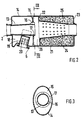
- FIGS. 2 and 3 Structural measures to increase the turbine efficiency and thus the overall efficiency of the internal combustion engine are implemented on the silencer shown in FIGS. 2 and 3.
- the main line 2 coming from the turbine 3 is connected to a central tube 13, which is fastened on the front side to the housing 14 of the silencer 5.
- the central tube 13 is passed through a partition 15 of the housing 14 and held in it with three radially protruding knobs 16. Between the knobs 16 are three passage areas of an aperture 17.
- the end 19 of the bypass line 6 projects into an annular space 18 located between the central tube 13 and the inner wall of the housing 14 and is fastened in the casing of the housing 14.
- the end 19 is closed at the end; on the circumference it is provided with radial bores 20, through which the bypass flow is throttled and soundproofed enters the annular space 18.
- a nozzle tube 21 is fastened coaxially to the central tube in the housing 14 with a collar 22 and is led out of the housing 14 to the outside at the end face 23.
- the nozzle tube 21 has a pattern of equidistant bores 24 on its jacket.
- the space between the nozzle tube and the inner wall of the housing 14 is filled with damping wool 25.
- the exhaust gas emerges from the central tube 13 and entrains the bypass flow flowing from the annular space 18 via the orifice opening 17 by ejector action.
- a mixing of the two exhaust gas flows takes place in the annular mixing space 26 located between the partition and the collar of the nozzle tube 21.
Landscapes
- Engineering & Computer Science (AREA)
- Chemical & Material Sciences (AREA)
- Combustion & Propulsion (AREA)
- Mechanical Engineering (AREA)
- General Engineering & Computer Science (AREA)
- Exhaust Silencers (AREA)
- Supercharger (AREA)
Description
Die Erfindung betrifft eine Abgasanlage mit Schalldämpfer für eine turboaufgeladene Hubkolben-Brennkraftmaschine nach dem Oberbegriff des Anspruchs 1.The invention relates to an exhaust system with a silencer for a turbocharged reciprocating piston internal combustion engine according to the preamble of claim 1.
Bei einer Abgasanlage, wie sie schematisch in Patentanmeldung P 37 15 061.8 dargestellt ist, werden die Abgase der Hauptleitung und Bypaßleitung in einem Schalldämpfer zusammengeführt, bevor sie ins Freie gelangen. Soll eine mit einer derartigen Abgasanlage ausgestattete Brennkraftmaschine als Flugmotor bei unterschiedlichen geodätischen Höhen optimal arbeiten, so muß die Stärke des Bypaßstroms zum Hauptstrom jeweils ein entsprechendes Verhältnis haben. Die Stelle im Schalldämpfer, an der sich die Abgasströme aus der Hauptleitung und Bypaßleitung vermischen, muß so gestaltet sein, daß eine verlustarme, möglichst geräuscharme Mischung erfolgen kann.In an exhaust system, as is shown schematically in patent application P 37 15 061.8, the exhaust gases of the main line and the bypass line are brought together in a silencer before they reach the outside. If an internal combustion engine equipped with such an exhaust system is to work optimally as an aircraft engine at different geodetic heights, the strength of the bypass flow to the main flow must in each case have a corresponding ratio. The point in the muffler where the exhaust gas flows from the main line and bypass line mix must be designed so that a low-loss, low-noise mixture can take place.
Es ist die Aufgabe der Erfindung, durch eine besondere Gestaltung der Abgasanlage und insbesondere des in sie eingesetzten Schalldämpfers, den Gesamtwirkungsgrad der Brennkraftmaschine zu verbessern und die Abgasgeräusche wirksam zu dämpfen.It is the object of the invention to improve the overall efficiency of the internal combustion engine and to effectively attenuate the exhaust noise by means of a special design of the exhaust system and in particular the muffler used in it.
Zur Lösung dieser Aufgabe dienen die kennzeichnenden Merkmale des Anspruchs 1. Wenn zu dem Abgasstrom in der Hauptleitung das Abgas der Bypaßleitung durch Ejektorwirkung zugemischt wird, erfolgt die Vermischung im turbulenten Randgebiet des durch den Hauptstrom erzeugten Freistrahls. Die Verwirbelungen und Strömungsverluste lassen sich auf diese Weise klein halten. Der Gesamtwirkungsgrad der Brennkraftmaschine wird erhöht. Zugleich wird durch die Ejektor-Zumischung im Schalldämpfer eine wirksame Dämpfung der Abgasgeräusche erzielt. Hierzu ist die Hauptleitung an einem im Schalldämpfer-Gehäuse befestigten Zentralrohr angeschlossen, von dem das Abgas als Freistrahl austritt. Der Bypaßstrom wird in eine diesen Freistrahl umgebende Blendenöffnung eingeblasen. Zusätzlich wirkt auf ihn der Sog des Freistrahls ein und bewirkt seine Vermischung mit der turbulenten Randzone des Freistrahls, ohne daß hierbei größere Strömungsverluste auftreten.The characteristic features of claim 1 serve to solve this problem. If the exhaust gas of the bypass line is added to the exhaust gas flow in the main line by ejector action, the mixing takes place in the turbulent peripheral area of the free jet generated by the main flow. The turbulence and flow losses can be kept small in this way. The overall efficiency of the internal combustion engine is increased. At the same time, the ejector admixture in the muffler effectively dampens the exhaust noise. For this purpose, the main line is connected to a central pipe fixed in the silencer housing, from which the exhaust gas emerges as a free jet. The bypass flow is blown into an aperture opening surrounding this free jet. In addition, the suction of the free jet acts on it and causes it to mix with the turbulent peripheral zone of the free jet without causing major flow losses.
Zur Druckrückgewinnung und damit zur Steigerung des Wirkungsgrades der Turbine ist das Zentralrohr in Strömungsrichtung diffusorartig erweitert; der Steigungswinkel beträgt ca. 4°. Der Bypaßstrom wird zur Geräuschminderung stark gedrosselt in einen das Zentralrohr umgebenen Ringraum des Schalldämpfer-Gehäuses eingeleitet und gelangt von dort zu der Blendenöffnung.For pressure recovery and thus to increase the efficiency of the turbine, the central tube is expanded in a diffuser-like manner; the pitch angle is approx. 4 °. The bypass flow is throttled to reduce noise in an annular space surrounding the central tube of the muffler housing and from there to the aperture.
In einem zum Zentralrohr koaxialen Düsenrohr, das mit einer Vielzahl von radialen Bohrungen versehen ist und mit einer Dämpfungswolle-Packung umgeben ist, wird der Schall des Haupt- und Bypaßstromes gemeinsam gedämpft.The sound of the main and bypass flow is damped together in a nozzle tube coaxial with the central tube, which is provided with a multiplicity of radial bores and is surrounded by a damping wool packing.
Ein Ausführungsbeispiel der Erfindung ist in der Zeichnung dargestellt und wird nachfolgend erläutert.An embodiment of the invention is shown in the drawing and is explained below.
Es zeigen:
- Fig. 1
- Schematische Darstellung einer Brennkraftmaschine mit Abgasturbolader,
- Fig. 2
- Längsschnitt durch einen Abgas-Schalldämpfer,
- Fig. 3
- Querschnitt des Schalldämpfers nach Linie III-III der Fig. 2.
- Fig. 1
- Schematic representation of an internal combustion engine with an exhaust gas turbocharger,
- Fig. 2
- Longitudinal section through an exhaust silencer,
- Fig. 3
- Cross section of the muffler according to line III-III of Fig. 2nd
Vom Zylinderkopf 1 einer Hubkolben-Brennkraftmaschine führt eine Hauptleitung 2 für Abgas zur Turbine 3 eines Turboladers 4 und von dort nach Durchströmen eines Schalldämpfers 5 ins Freie. Parallel zur Turbine 3 liegt eine Bypaßleitung 6, die ebenfalls in den Schalldämpfer 5 einmündet. Im Schalldämpfer 5 vermischt sich der Bypaßstrom mit dem Abgasstrom der Hauptleitung 2. In die Bypaßleitung 6 ist ein Bypaßventil 7 eingesetzt, über das je nach seiner Stellung mehr oder weniger Abgas in den Schalldämpfer 5 gelangt, ohne die Turbine 3 zu beaufschlagen.A
Die Turbine 3 treibt einen Verdichter 8, mit dem Frischluft über einen Luftfilter 9 angesaugt und unter Druckerhöhung in eine Ladeluftleitung 10 gefördert wird. Die Ladeluftleitung 10 führt über einen Ladeluftkühler 11 zu einem eine Einspritzanlage steuernden Luftmengenmesser 12 und von dort zum Zylinderkopf 1 der Brennkraftmaschine.The turbine 3 drives a
Je höher der Volumenstrom der die Turbine beaufschlagende Abgase ist, umso höher ist die Drehzahl und Leistung des Verdichters. Mit der Erhöhung der Verdichterleistung steigt der Volumenstrom und der Druck der von ihm geförderten Ladeluft. Der erzielbare Ladedruck ist auch davon abhängig, wie hoch der atmosphärische Druck der in den Verdichter eintretenden Frischluft ist. Da dieser Zuführdruck mit zunehmender geodätischer Höhe abnimmt, würde sich auch der Ladedruck entsprechend verringern. Um das zu verhindern, wird das Bypaßventil mit zunehmender geodätischer Höhe, in der sich die Brennkraftmaschine befindet, immer weiter geschlossen. Das Durchsatzverhältnis der Bypaßleitung zur Hauptleitung, das in Meereshöhe ca. 45% zu 55% beträgt, wird bei maximaler geodätischer Höhe auf 0% zu 100% reduziert.The higher the volume flow of the exhaust gases acting on the turbine, the higher the speed and power of the compressor. As the compressor output increases, the volume flow and the pressure of the charge air it pumps up increase. The achievable boost pressure also depends on how high the atmospheric pressure of the fresh air entering the compressor is. Since this feed pressure decreases with increasing geodetic height, the boost pressure would also decrease accordingly. To prevent this, the bypass valve is closed more and more with increasing geodetic height at which the internal combustion engine is located. The throughput ratio of the bypass line to the main line, which is approx. 45% to 55% at sea level, is reduced to 0% to 100% at maximum geodetic height.
Konstruktive Maßnahmen zur Erhöhung des Turbinenwirkungsgrades und damit des Gesamtwirkungsgrades der Brennkraftmaschine sind an dem in Fig. 2 und Fig. 3 dargestellten Schalldämpfer verwirklicht. Die von der Turbine 3 kommende Hauptleitung 2 ist an ein Zentralrohr 13 angeschlossen, das stirnseitig am Gehäuse 14 des Schalldämpfers 5 befestigt ist. Am anderen Ende ist das Zentralrohr 13 durch eine Trennwand 15 des Gehäuses 14 durchgeführt und in ihr mit drei radial vorstehenden Noppen 16 gehalten. Zwischen den Noppen 16 liegen drei Durchtrittsflächen einer Blendenöffnung 17.Structural measures to increase the turbine efficiency and thus the overall efficiency of the internal combustion engine are implemented on the silencer shown in FIGS. 2 and 3. The
In einen zwischen dem Zentralrohr 13 und der Innenwand des Gehäuses 14 gelegenen Ringraum 18 ragt das Ende 19 der Bypaßleitung 6 hinein und ist im Mantel des Gehäuses 14 befestigt. Stirnseitig ist das Ende 19 verschlossen; am Umfang ist es mit Radialbohrungen 20 versehen, durch die hindurch der Bypaßstrom gedrosselt und schallgedämpft in den Ringraum 18 eintritt.The
Koaxial zum Zentralrohr ist ein Düsenrohr 21 im Gehäuse 14 mit einem Kragen 22 befestigt und an der Stirnseite 23 aus dem Gehäuse 14 ins Freie herausgeführt. Das Düsenrohr 21 weist an seinem Mantel ein Muster äquidistanter Bohrungen 24 auf. Der Zwischenraum zwischen dem Düsenrohr und der Innenwand des Gehäuses 14 ist mit Dämpfungswolle 25 ausgefüllt.A
Das Abgas tritt aus dem Zentralrohr 13 aus und reißt den aus dem Ringraum 18 über die Blendenöffnung 17 fließenden Bypaßstrom durch Ejektorwirkung mit. In dem zwischen der Trennwand und dem Kragen des Düsenrohrs 21 liegenden ringförmigen Mischraum 26 findet eine Vermischung beider Abgasströme statt. Bei Eintritt dieses gemeinsamen Abgasstromes in das Düsenrohr 21 wird der größte Teil seiner Schallenergie durch die Bohrungen 24 in die Dämpfungswolle 25 eingeleitet und von ihr absorbiert.The exhaust gas emerges from the
Claims (9)
- An exhaust device with a silencer for a reciprocating-piston internal combustion engine supercharged by a turbocharger, the exhaust duct comprising a main duct which leads to the turbine of the turbocharger and a by-pass duct which avoids the turbine and is controlled by a by-pass valve, characterized in that the main duct (2) and the by-pass duct (6) enter the housing (14) of the silencer (5) and are orientated with respect to each other in such a way that the exhaust flow from the main duct (2) exerts an ejector effect upon the exhaust flow from the by-pass duct (6).
- An exhaust device with a silencer according to Claim 1, characterized in that the main duct (2) opens into a central tube (13) fixed to the housing, and the by-pass duct (6) opens into an annular space (18) lying between the central tube (13) and the inner wall of the housing (14) and connected by way of a diaphragm opening (17) surrounding the outlet end of the central tube (13) to a coaxial jet tube (21) fixed to the housing.
- An exhaust device with a silencer according to Claim 2, characterized in that a free annular mixing chamber (26) extending as far as the inner wall of the housing (14) is provided between the diaphragm opening (17) and the jet tube (21).
- An exhaust device with a silencer according to Claim 2, characterized in that the central tube (13) is enlarged in the manner of a diffusor in the flow direction.
- An exhaust device with a silencer according to Claim 2, characterized in that the jet tube (21) is provided all round with a plurality of radial apertures (24) which are covered by the damping wool (25) lying between the jet tube (21) and the inner wall of the housing (14).
- An exhaust device with a silencer according to Claim 5, characterized in that the apertures are formed as equidistant bores (24) of equal size and extend over the greater part of the length of the jet tube.
- An exhaust device with a silencer according to any one of Claims 1 to 6, characterized in that the housing (14) of the silencer (5) has an elliptical cross-section.
- An exhaust device with a silencer according to Claims 1 and 2, characterized in that the end (19) of the by-pass duct (6) projecting into the annular space (18) of the housing (14) is closed at its end face and is provided with radial bores (20) all round its generated surface.
- An exhaust device with a silencer according to Claims 1 to 8, characterized in that by closing the by-pass valve (7) the throughput ratio of the bypass duct (6) to the main duct (2) is reduced as the geodetic height of the internal combustion engine increases.
Applications Claiming Priority (2)
| Application Number | Priority Date | Filing Date | Title |
|---|---|---|---|
| DE19873718875 DE3718875A1 (en) | 1987-06-05 | 1987-06-05 | EXHAUST SYSTEM WITH MUFFLER FOR AN INTERNAL COMBUSTION ENGINE |
| DE3718875 | 1987-06-05 |
Publications (3)
| Publication Number | Publication Date |
|---|---|
| EP0293577A2 EP0293577A2 (en) | 1988-12-07 |
| EP0293577A3 EP0293577A3 (en) | 1990-08-01 |
| EP0293577B1 true EP0293577B1 (en) | 1992-01-02 |
Family
ID=6329138
Family Applications (1)
| Application Number | Title | Priority Date | Filing Date |
|---|---|---|---|
| EP88105788A Expired - Lifetime EP0293577B1 (en) | 1987-06-05 | 1988-04-12 | Exhaust device with silencer for internal combustion engines |
Country Status (4)
| Country | Link |
|---|---|
| US (1) | US4807439A (en) |
| EP (1) | EP0293577B1 (en) |
| JP (1) | JPS63309708A (en) |
| DE (2) | DE3718875A1 (en) |
Families Citing this family (15)
| Publication number | Priority date | Publication date | Assignee | Title |
|---|---|---|---|---|
| US5761946A (en) * | 1992-06-30 | 1998-06-09 | Ppg Industries, Inc. | Method of making spacer stock |
| US5177916A (en) * | 1990-09-04 | 1993-01-12 | Ppg Industries, Inc. | Spacer and spacer frame for an insulating glazing unit and method of making same |
| CA2049703C (en) | 1990-09-04 | 1995-01-17 | Robert B. Hodek | Low thermal conducting spacer assembly for an insulating glazing unit and method of making same |
| US5675944A (en) * | 1990-09-04 | 1997-10-14 | P.P.G. Industries, Inc. | Low thermal conducting spacer assembly for an insulating glazing unit and method of making same |
| US5255481A (en) | 1990-09-04 | 1993-10-26 | Ppg Industries, Inc. | Spacer and spacer frame for an insulating glazing unit and method of making same |
| US5916136A (en) * | 1997-10-02 | 1999-06-29 | Ettere; Mark | Aspiration device for vehicle engine exhaust system |
| US6202413B1 (en) | 1999-02-04 | 2001-03-20 | Cummins Engine Company, Inc. | Multiple nozzle ejector for wastegated turbomachinery |
| US6688425B2 (en) * | 2001-10-09 | 2004-02-10 | Siemens Vdo Automotive, Inc. | Induction system with low pass filter for turbo charger applications |
| US7017706B2 (en) * | 2001-12-21 | 2006-03-28 | Honeywell International, Inc. | Turbine noise absorber |
| RU2301899C1 (en) * | 2006-01-10 | 2007-06-27 | Общество с ограниченной ответственностью "Федеральный учебный межвузовский научный производственный центр" | Method of and device to control gas exchange in turbocharged diesel engine |
| US20090139165A1 (en) * | 2007-12-04 | 2009-06-04 | Intigral, Inc. | Insulating glass unit |
| US20090139163A1 (en) * | 2007-12-04 | 2009-06-04 | Intigral, Inc. | Insulating glass unit |
| US20090139164A1 (en) * | 2007-12-04 | 2009-06-04 | Intigral, Inc. | Insulating glass unit |
| RU2704659C2 (en) * | 2017-07-26 | 2019-10-30 | Общество с ограниченной ответственностью "УралГазРемонт" | Method for cooling of gas transmission turbine shaft and transmission elements instrumentation and device for implementation thereof |
| CA3217527A1 (en) * | 2020-01-13 | 2021-07-13 | Polaris Industries Inc. | Turbocharger lubrication system for a two-stroke engine |
Family Cites Families (7)
| Publication number | Priority date | Publication date | Assignee | Title |
|---|---|---|---|---|
| GB896584A (en) * | 1957-09-11 | 1962-05-16 | Garrett Corp | Control apparatus for internal combustion engine turbosuperchargers |
| JPS5188405A (en) * | 1975-02-01 | 1976-08-03 | KOROGASUSHORISOCHI | |
| FR2338382A1 (en) * | 1976-01-19 | 1977-08-12 | Inst Francais Du Petrole | IC engine turbocharger assembly - has jet pump in outlet duct from turbine and supplied from its inlet duct to reduce turbine outlet pressure |
| DE2913488A1 (en) * | 1979-04-04 | 1980-10-09 | Porsche Ag | DEVICE FOR REGULATING THE CHARGE PRESSURE IN AN INTERNAL COMBUSTION ENGINE OPERATING WITH EXHAUST GAS CHARGING |
| DE3048933A1 (en) * | 1980-12-24 | 1982-07-15 | Dr.Ing.H.C. F. Porsche Ag, 7000 Stuttgart | DEVICE FOR REGULATING THE CHARGING PRESSURE IN AN COMBUSTION ENGINE OPERATING WITH EXHAUST GAS CHARGING |
| FR2496758A4 (en) * | 1979-04-04 | 1982-06-25 | Porsche Ag | Exhaust supercharged IC engine charge pressure control - has valve regulating ejector nozzle flow cross=section |
| US4463564A (en) * | 1981-10-23 | 1984-08-07 | The Garrett Corporation | Turbocharger turbine housing assembly |
-
1987
- 1987-06-05 DE DE19873718875 patent/DE3718875A1/en not_active Withdrawn
-
1988
- 1988-04-12 EP EP88105788A patent/EP0293577B1/en not_active Expired - Lifetime
- 1988-04-12 DE DE8888105788T patent/DE3867318D1/en not_active Expired - Lifetime
- 1988-06-03 JP JP63135733A patent/JPS63309708A/en active Pending
- 1988-06-03 US US07/201,930 patent/US4807439A/en not_active Expired - Fee Related
Also Published As
| Publication number | Publication date |
|---|---|
| JPS63309708A (en) | 1988-12-16 |
| EP0293577A3 (en) | 1990-08-01 |
| US4807439A (en) | 1989-02-28 |
| DE3718875A1 (en) | 1988-12-22 |
| EP0293577A2 (en) | 1988-12-07 |
| DE3867318D1 (en) | 1992-02-13 |
Similar Documents
| Publication | Publication Date | Title |
|---|---|---|
| EP0293577B1 (en) | Exhaust device with silencer for internal combustion engines | |
| DE10116643C2 (en) | reciprocating internal combustion engine | |
| DE3302224C2 (en) | ||
| DE2500496A1 (en) | COMPRESSOR DEVICE | |
| DE1061132B (en) | Turbocharger for multi-cylinder internal combustion engines | |
| DE10015291A1 (en) | Turbocharged V-engine has two different sizes of turbocharger with series operation at low engine speeds and parallel operation at high engine speeds | |
| DE10260778A1 (en) | Exhaust gas turbocharger for an internal combustion engine | |
| EP1881173B1 (en) | Diffusor for internal combustion engine and engine with such a diffusor | |
| DE102005046507A1 (en) | Internal combustion engine comprises exhaust gas turbochargers each having a turbine with a bypass having an outflow valve integrated in the turbine housing | |
| DE4312077C1 (en) | Exhaust gas turbocharger for IC engine - has at least one turbine and compressor, turbine having inflow and outflow sides, turbine wheel, housing with spirally-shaped flow channel and variable guide blade crown | |
| DE102016205327A1 (en) | Exhaust after treatment system and internal combustion engine | |
| DE3121341C2 (en) | Exhaust pipe system between a multi-cylinder internal combustion engine charged according to the stagnation principle and an exhaust gas turbocharger | |
| DE102016205299A1 (en) | Internal combustion engine with exhaust aftertreatment system | |
| DE19857577A1 (en) | Exhaust gas feedback system for internal combustion engine | |
| DE102005019937B3 (en) | Turbine for exhaust gas turbocharger, has auxiliary blades, which are dimensioned such that throughput parameter of turbine wheel blades is set to throughput parameter of auxiliary blades in certain ratio, which is greater than fifteen | |
| EP1061265B1 (en) | Turbocharger for a slow speed diesel engine | |
| DE10215741A1 (en) | Shunt outlet for silencing an idle bypass valve | |
| DE4222087C2 (en) | Reduced pollutant diesel engine | |
| DE102016003742A1 (en) | Exhaust after-treatment system, internal combustion engine and method for operating the same | |
| DE102016003743A1 (en) | Exhaust after treatment system and internal combustion engine | |
| DE102016113389A1 (en) | Mixing device for an exhaust aftertreatment system, exhaust aftertreatment system and internal combustion engine | |
| DE112004001010B4 (en) | Internal combustion engine with exhaust gas recirculation system and pulse converter in the exhaust system | |
| DE102016205274A1 (en) | Exhaust after treatment system and internal combustion engine | |
| DE102012008990A1 (en) | Injection system for injecting secondary air for Otto combustion engine, has pressure line connected with secondary air fan at output side, and reducing unit reducing propagation of airborne sound over suction line and/or pressure line | |
| DE2350091C2 (en) | Exhaust gas turbocharger for precompressing the combustion air of internal combustion engines |
Legal Events
| Date | Code | Title | Description |
|---|---|---|---|
| PUAI | Public reference made under article 153(3) epc to a published international application that has entered the european phase |
Free format text: ORIGINAL CODE: 0009012 |
|
| AK | Designated contracting states |
Kind code of ref document: A2 Designated state(s): DE FR GB IT SE |
|
| PUAL | Search report despatched |
Free format text: ORIGINAL CODE: 0009013 |
|
| AK | Designated contracting states |
Kind code of ref document: A3 Designated state(s): DE FR GB IT SE |
|
| 17P | Request for examination filed |
Effective date: 19901210 |
|
| 17Q | First examination report despatched |
Effective date: 19910503 |
|
| ITF | It: translation for a ep patent filed | ||
| GRAA | (expected) grant |
Free format text: ORIGINAL CODE: 0009210 |
|
| AK | Designated contracting states |
Kind code of ref document: B1 Designated state(s): DE FR GB IT SE |
|
| GBT | Gb: translation of ep patent filed (gb section 77(6)(a)/1977) | ||
| REF | Corresponds to: |
Ref document number: 3867318 Country of ref document: DE Date of ref document: 19920213 |
|
| PGFP | Annual fee paid to national office [announced via postgrant information from national office to epo] |
Ref country code: SE Payment date: 19920325 Year of fee payment: 5 |
|
| PGFP | Annual fee paid to national office [announced via postgrant information from national office to epo] |
Ref country code: DE Payment date: 19920331 Year of fee payment: 5 |
|
| PGFP | Annual fee paid to national office [announced via postgrant information from national office to epo] |
Ref country code: GB Payment date: 19920402 Year of fee payment: 5 |
|
| PGFP | Annual fee paid to national office [announced via postgrant information from national office to epo] |
Ref country code: FR Payment date: 19920430 Year of fee payment: 5 |
|
| ET | Fr: translation filed | ||
| PLBE | No opposition filed within time limit |
Free format text: ORIGINAL CODE: 0009261 |
|
| STAA | Information on the status of an ep patent application or granted ep patent |
Free format text: STATUS: NO OPPOSITION FILED WITHIN TIME LIMIT |
|
| 26N | No opposition filed | ||
| PG25 | Lapsed in a contracting state [announced via postgrant information from national office to epo] |
Ref country code: GB Effective date: 19930412 |
|
| PG25 | Lapsed in a contracting state [announced via postgrant information from national office to epo] |
Ref country code: SE Effective date: 19930413 |
|
| GBPC | Gb: european patent ceased through non-payment of renewal fee |
Effective date: 19930412 |
|
| PG25 | Lapsed in a contracting state [announced via postgrant information from national office to epo] |
Ref country code: FR Effective date: 19931229 |
|
| PG25 | Lapsed in a contracting state [announced via postgrant information from national office to epo] |
Ref country code: DE Effective date: 19940101 |
|
| REG | Reference to a national code |
Ref country code: FR Ref legal event code: ST |
|
| EUG | Se: european patent has lapsed |
Ref document number: 88105788.9 Effective date: 19931110 |
|
| PG25 | Lapsed in a contracting state [announced via postgrant information from national office to epo] |
Ref country code: IT Free format text: LAPSE BECAUSE OF NON-PAYMENT OF DUE FEES;WARNING: LAPSES OF ITALIAN PATENTS WITH EFFECTIVE DATE BEFORE 2007 MAY HAVE OCCURRED AT ANY TIME BEFORE 2007. THE CORRECT EFFECTIVE DATE MAY BE DIFFERENT FROM THE ONE RECORDED. Effective date: 20050412 |