EP3244035B1 - Compressor, exhaust gas turbocharger and combustion engine - Google Patents
Compressor, exhaust gas turbocharger and combustion engine Download PDFInfo
- Publication number
- EP3244035B1 EP3244035B1 EP17162834.0A EP17162834A EP3244035B1 EP 3244035 B1 EP3244035 B1 EP 3244035B1 EP 17162834 A EP17162834 A EP 17162834A EP 3244035 B1 EP3244035 B1 EP 3244035B1
- Authority
- EP
- European Patent Office
- Prior art keywords
- compressor
- channel
- egr
- inlet
- exhaust gas
- Prior art date
- Legal status (The legal status is an assumption and is not a legal conclusion. Google has not performed a legal analysis and makes no representation as to the accuracy of the status listed.)
- Active
Links
Images

Classifications
-
- F—MECHANICAL ENGINEERING; LIGHTING; HEATING; WEAPONS; BLASTING
- F02—COMBUSTION ENGINES; HOT-GAS OR COMBUSTION-PRODUCT ENGINE PLANTS
- F02B—INTERNAL-COMBUSTION PISTON ENGINES; COMBUSTION ENGINES IN GENERAL
- F02B37/00—Engines characterised by provision of pumps driven at least for part of the time by exhaust
-
- F—MECHANICAL ENGINEERING; LIGHTING; HEATING; WEAPONS; BLASTING
- F02—COMBUSTION ENGINES; HOT-GAS OR COMBUSTION-PRODUCT ENGINE PLANTS
- F02C—GAS-TURBINE PLANTS; AIR INTAKES FOR JET-PROPULSION PLANTS; CONTROLLING FUEL SUPPLY IN AIR-BREATHING JET-PROPULSION PLANTS
- F02C6/00—Plural gas-turbine plants; Combinations of gas-turbine plants with other apparatus; Adaptations of gas- turbine plants for special use
- F02C6/04—Gas-turbine plants providing heated or pressurised working fluid for other apparatus, e.g. without mechanical power output
- F02C6/10—Gas-turbine plants providing heated or pressurised working fluid for other apparatus, e.g. without mechanical power output supplying working fluid to a user, e.g. a chemical process, which returns working fluid to a turbine of the plant
- F02C6/12—Turbochargers, i.e. plants for augmenting mechanical power output of internal-combustion piston engines by increase of charge pressure
-
- F—MECHANICAL ENGINEERING; LIGHTING; HEATING; WEAPONS; BLASTING
- F02—COMBUSTION ENGINES; HOT-GAS OR COMBUSTION-PRODUCT ENGINE PLANTS
- F02M—SUPPLYING COMBUSTION ENGINES IN GENERAL WITH COMBUSTIBLE MIXTURES OR CONSTITUENTS THEREOF
- F02M26/00—Engine-pertinent apparatus for adding exhaust gases to combustion-air, main fuel or fuel-air mixture, e.g. by exhaust gas recirculation [EGR] systems
- F02M26/02—EGR systems specially adapted for supercharged engines
- F02M26/04—EGR systems specially adapted for supercharged engines with a single turbocharger
- F02M26/06—Low pressure loops, i.e. wherein recirculated exhaust gas is taken out from the exhaust downstream of the turbocharger turbine and reintroduced into the intake system upstream of the compressor
-
- F—MECHANICAL ENGINEERING; LIGHTING; HEATING; WEAPONS; BLASTING
- F02—COMBUSTION ENGINES; HOT-GAS OR COMBUSTION-PRODUCT ENGINE PLANTS
- F02M—SUPPLYING COMBUSTION ENGINES IN GENERAL WITH COMBUSTIBLE MIXTURES OR CONSTITUENTS THEREOF
- F02M26/00—Engine-pertinent apparatus for adding exhaust gases to combustion-air, main fuel or fuel-air mixture, e.g. by exhaust gas recirculation [EGR] systems
- F02M26/02—EGR systems specially adapted for supercharged engines
- F02M26/09—Constructional details, e.g. structural combinations of EGR systems and supercharger systems; Arrangement of the EGR and supercharger systems with respect to the engine
-
- F—MECHANICAL ENGINEERING; LIGHTING; HEATING; WEAPONS; BLASTING
- F02—COMBUSTION ENGINES; HOT-GAS OR COMBUSTION-PRODUCT ENGINE PLANTS
- F02M—SUPPLYING COMBUSTION ENGINES IN GENERAL WITH COMBUSTIBLE MIXTURES OR CONSTITUENTS THEREOF
- F02M26/00—Engine-pertinent apparatus for adding exhaust gases to combustion-air, main fuel or fuel-air mixture, e.g. by exhaust gas recirculation [EGR] systems
- F02M26/13—Arrangement or layout of EGR passages, e.g. in relation to specific engine parts or for incorporation of accessories
- F02M26/17—Arrangement or layout of EGR passages, e.g. in relation to specific engine parts or for incorporation of accessories in relation to the intake system
- F02M26/19—Means for improving the mixing of air and recirculated exhaust gases, e.g. venturis or multiple openings to the intake system
-
- F—MECHANICAL ENGINEERING; LIGHTING; HEATING; WEAPONS; BLASTING
- F04—POSITIVE - DISPLACEMENT MACHINES FOR LIQUIDS; PUMPS FOR LIQUIDS OR ELASTIC FLUIDS
- F04D—NON-POSITIVE-DISPLACEMENT PUMPS
- F04D29/00—Details, component parts, or accessories
- F04D29/40—Casings; Connections of working fluid
- F04D29/42—Casings; Connections of working fluid for radial or helico-centrifugal pumps
- F04D29/4206—Casings; Connections of working fluid for radial or helico-centrifugal pumps especially adapted for elastic fluid pumps
- F04D29/4213—Casings; Connections of working fluid for radial or helico-centrifugal pumps especially adapted for elastic fluid pumps suction ports
-
- F—MECHANICAL ENGINEERING; LIGHTING; HEATING; WEAPONS; BLASTING
- F05—INDEXING SCHEMES RELATING TO ENGINES OR PUMPS IN VARIOUS SUBCLASSES OF CLASSES F01-F04
- F05D—INDEXING SCHEME FOR ASPECTS RELATING TO NON-POSITIVE-DISPLACEMENT MACHINES OR ENGINES, GAS-TURBINES OR JET-PROPULSION PLANTS
- F05D2220/00—Application
- F05D2220/40—Application in turbochargers
-
- F—MECHANICAL ENGINEERING; LIGHTING; HEATING; WEAPONS; BLASTING
- F05—INDEXING SCHEMES RELATING TO ENGINES OR PUMPS IN VARIOUS SUBCLASSES OF CLASSES F01-F04
- F05D—INDEXING SCHEME FOR ASPECTS RELATING TO NON-POSITIVE-DISPLACEMENT MACHINES OR ENGINES, GAS-TURBINES OR JET-PROPULSION PLANTS
- F05D2260/00—Function
- F05D2260/14—Preswirling
-
- Y—GENERAL TAGGING OF NEW TECHNOLOGICAL DEVELOPMENTS; GENERAL TAGGING OF CROSS-SECTIONAL TECHNOLOGIES SPANNING OVER SEVERAL SECTIONS OF THE IPC; TECHNICAL SUBJECTS COVERED BY FORMER USPC CROSS-REFERENCE ART COLLECTIONS [XRACs] AND DIGESTS
- Y02—TECHNOLOGIES OR APPLICATIONS FOR MITIGATION OR ADAPTATION AGAINST CLIMATE CHANGE
- Y02T—CLIMATE CHANGE MITIGATION TECHNOLOGIES RELATED TO TRANSPORTATION
- Y02T10/00—Road transport of goods or passengers
- Y02T10/10—Internal combustion engine [ICE] based vehicles
- Y02T10/12—Improving ICE efficiencies
Description
Die Erfindung betrifft einen Verdichter, einen einen Verdichter umfassenden Abgasturbolader und eine einen Verdichter umfassende Brennkraftmaschine.The invention relates to a compressor, a compressor comprising an exhaust gas turbocharger and a compressor comprising an internal combustion engine.
In einem Verdichter einer Brennkraftmaschine wird das über einen Frischgasstrang einem Verbrennungsmotor der Brennkraftmaschine zugeführte Frischgas verdichtet.In a compressor of an internal combustion engine, the fresh gas supplied via a fresh gas train to an internal combustion engine of the internal combustion engine is compressed.
Bei heutigen Brennkraftmaschinen wird häufig eine Niederdruck-Abgasrückführung (ND-AGR) eingesetzt, um Emissionsgrenzwerte zu erreichen. Dabei wird stromab einer Turbine eines Abgasturboladers aus einem Abgasstrang entnommenes Abgas vor dem Verdichter des Abgasturboladers in den Frischgasstrang der Brennkraftmaschine eingeleitet, von dem Verdichter zusammen mit dem Frischgas angesaugt und in die Brennräume des Verbrennungsmotors rückgeführt. Dabei sollte die Einleitung des rückgeführten Abgases möglichst nahe vor dem Verdichter erfolgen, um eine nicht gewünschte Kondensatbildung im Frischgas zu vermeiden oder gering zu halten. Für die Regelung der ND-AGR-Rate wird in die ND-AGR-Einleitung vor dem Verdichtereintritt in der Regel ein Regelventil integriert.In today's internal combustion engines, a low-pressure exhaust gas recirculation (LP-EGR) is often used to achieve emission limits. In this case, exhaust gas taken from an exhaust gas line downstream of a turbine of an exhaust gas turbocharger is introduced into the fresh gas train of the internal combustion engine, sucked by the compressor together with the fresh gas and returned to the combustion chambers of the internal combustion engine. The introduction of the recirculated exhaust gas should be as close as possible in front of the compressor in order to avoid or keep unwanted condensate formation in the fresh gas. For regulating the LP EGR rate, a control valve is usually integrated into the LP EGR introduction prior to compressor entry.
Aus der
Weiterhin ist aus der
Die
Die
Die
Ausgehend von diesem Stand der Technik lag der Erfindung die Aufgabe zugrunde, eine vorteilhafte Möglichkeit der Einleitung rückzuführenden Abgases stromauf eines Verdichters in einen mittels des Verdichters zu verdichtenden Gasstrom anzugeben.Based on this prior art, the present invention seeks to provide an advantageous way of introducing recirculating exhaust gas upstream of a compressor in a gas stream to be compressed by means of the compressor.
Diese Aufgabe wird mittels eines Verdichters gemäß dem Patentanspruch 1 gelöst. Ein Abgasturbolader mit einem solchen Verdichter sowie eine Brennkraftmaschine mit einem solchen Verdichter sind Gegenstände der Patentansprüche 5 und 6. Vorteilhafte Ausgestaltungen des erfindungsgemäßen Verdichters und damit des erfindungsgemäßen Abgasturboladers und/oder der erfindungsgemäßen Brennkraftmaschine sind Gegenstände der weiteren Patentansprüche und/oder ergeben sich aus der nachfolgenden Beschreibung der Erfindung.This object is achieved by means of a compressor according to the patent claim 1. An exhaust gas turbocharger with such a compressor and an internal combustion engine with such a compressor are subject matter of claims 5 and 6. Advantageous embodiments of the compressor according to the invention and thus of the exhaust gas turbocharger and / or the internal combustion engine according to the invention are objects of the other claims and / or emerge from the following Description of the invention.
Ein Verdichter, bei dem es sich insbesondere um einen Radialverdichter handeln kann und der ein (ein- oder mehrteiliges) Gehäuse umfasst, das einen Strömungsraum, innerhalb dessen ein Verdichterlaufrad drehbar gelagert ist, und einen Einlasskanal, der sich zwischen einem Verdichtereinlass und dem Strömungsraum erstreckt, ausbildet, wobei in den Einlasskanal ein AGR-Kanal für eine Abgasrückführung mündet, ist einerseits dadurch gekennzeichnet, dass der AGR-Kanal in einem umfangsseitig geschlossen ausgebildeten AGR-Kanalabschnitt bogenförmig um zumindest einen Abschnitt des Umfangs des Einlasskanals herum verläuft, so dass ein AGR-Kanalabschnittseinlass (d.h. der Einlass des AGR-Kanalabschnitts) in Umfangsrichtung des Einlasskanals zu der (insbesondere einer einzigen) AGR-Kanalmündung versetzt angeordnet ist. Auf diese Weise kann ein Drall der Strömung des rückzuführenden Abgases (um eine Längsachse des Einlasskanals) realisiert werden, wodurch ein im Wesentlichen tangentiales Einströmen des rückgeführten Abgases in die über den Einlasskanal geführte Gasströmung realisiert werden kann, was zu einer vorteilhaften, insbesondere strömungstechnisch vorteilhaften Vermischung des rückgeführten Abgases mit der Gasströmung führen kann.A compressor, which may in particular be a centrifugal compressor and which comprises a housing (one or more parts) having a flow space within which a compressor impeller is rotatably mounted, and an inlet channel extending between a compressor inlet and the flow space , forms, wherein in the inlet channel an EGR passage for exhaust gas recirculation opens, is characterized on the one hand in that the EGR passage in a circumferentially closed formed EGR passage section extends arcuately around at least a portion of the circumference of the inlet channel, so an EGR passage section inlet (ie the inlet of the EGR passage section) is arranged offset in the circumferential direction of the inlet passage to the (in particular a single) EGR passage opening. In this way, a swirl of the flow of the exhaust gas to be recirculated can be realized (about a longitudinal axis of the inlet channel), whereby a substantially tangential inflow of the recirculated exhaust gas can be realized in the guided over the inlet channel gas flow, resulting in an advantageous, in particular fluidically advantageous mixing the recirculated exhaust gas can lead to the gas flow.
Die versetzte Anordnung des AGR-Kanalabschnittseinlasses und AGR-Kanalmündung bezieht sich zumindest auf deren Kanalmitten, vorzugsweise jedoch auf jeweils den AGR-Kanalabschnittseinlass und die AGR-Kanalmündung insgesamt.The staggered arrangement of the EGR passage section inlet and EGR passage throat refers at least to their passage centers, but preferably each to the EGR passage section inlet and the EGR passage mouth as a whole.
Weiterhin ist vorgesehen dass der AGR-Kanalabschnitt (mindestens) zwei Teilkanäle umfasst, wobei diese zwei Teilkanäle ausgehend von dem AGR-Kanalabschnittseinlass in entgegengesetzten Umfangsrichtungen bogenförmig um zumindest einen Abschnitt des Umfangs des Einlasskanals herum verlaufen. Dies kann insbesondere aus Gründen der räumlichen Integration des AGR-Kanals sinnvoll sein, wenn relativ große AGR-Raten für eine einen solchen Verdichter aufweisende Brennkraftmaschine realisiert werden sollen.It is further contemplated that the EGR passage section comprises (at least) two subchannels, wherein these two subchannels extend arcuately from the EGR passage section inlet in opposite circumferential directions about at least a portion of the circumference of the intake passage. This may be useful, in particular for reasons of spatial integration of the EGR channel, when relatively large EGR rates are to be realized for an internal combustion engine having such a compressor.
Eine Erzeugung eines Dralls in der für das Verdichterlaufrad vorgesehenen Drehrichtung wird dabei in vorteilhafter Weise dadurch erreicht, dass der kleinste Strömungsquerschnitt desjenigen Teilkanals, dessen Krümmungsrichtung der für das Verdichterlaufrad vorgesehenen Drehrichtung entspricht, größer als der kleinste Strömungsquerschnitt des anderen Teilkanals ist. Auf diese Weise kann erreicht werden, dass über den AGR-Kanal rückzuführendes Abgas selbsttätig zu einem größeren Anteil über den "größeren" Teilkanal, dessen Krümmungsrichtung der für das Verdichterlaufrad vorgesehenen Drehrichtung entspricht, strömt, wodurch sichergestellt werden kann, dass das insgesamt in den Einlasskanal einströmende Abgas, das über beide Teilkanäle zugeführt wurde, die gewünschte Drallrichtung aufweist.A generation of a twist in the direction of rotation provided for the compressor impeller is achieved in an advantageous manner in that the smallest flow cross section of that partial channel whose direction of curvature corresponds to the direction of rotation provided for the compressor impeller is greater than the smallest flow cross section of the other partial channel. In this way, it can be achieved that exhaust gas to be recirculated via the EGR passage automatically flows to a greater extent via the "larger" subchannel, the direction of curvature of which corresponds to the direction of rotation provided for the compressor wheel, thereby ensuring that the exhaust gas can flow into the intake passage altogether incoming exhaust gas, which has been supplied via both sub-channels, having the desired twisting direction.
Vorzugsweise kann vorgesehen sein, dass sich die AGR-Kanalmündung über maximal die Hälfte, maximal ein Drittel oder maximal ein Viertel des Umfangs des Einlasskanals erstreckt, wodurch das über den AGR-Kanal rückzuführende Abgas durch einen relativ kleinen Öffnungsquerschnitt in den Einlasskanal überströmen muss. Dies kann zu relativ hohen Strömungsgeschwindigkeiten für das rückzuführende Abgas führen, die sich vorteilhaft auf die Vermischung mit der über den Einlasskanal geführten Gasströmung auswirken können. Weiterhin bevorzugt kann noch vorgesehen sein, dass der AGR-Kanal derart ausgebildet ist, dass über diesen in den Einlasskanal eintretendes Abgas einen Drall mit einer der für das Verdichterlaufrad vorgesehenen Drehrichtung entsprechenden Drallrichtung aufweist. Dieser Drall des eintretenden Abgases kann auch einen entsprechenden Drall in der über den Einlasskanal zu dem Verdichterlaufrad geführten Gasströmung bewirken oder verstärken, was sich in positiver Weise auf das Betriebsverhalten des Verdichters auswirken kann.Preferably, it may be provided that the EGR channel opening extends over a maximum of half, a maximum of one third or a maximum of a quarter of the circumference of the inlet channel, whereby the exhaust gas to be recirculated via the EGR channel has to flow through a relatively small opening cross section into the inlet channel. This can lead to relatively high flow rates for the exhaust gas to be recirculated, which can have an advantageous effect on the mixing with the gas flow guided via the inlet channel. Furthermore preferably, it can be provided that the EGR passage is designed in such a way that via this exhaust gas entering the inlet duct, there is a swirl with one swirl direction corresponding to the direction of rotation provided for the compressor runner. This swirl of the incoming exhaust gas can also cause or increase a corresponding swirl in the gas flow guided via the inlet channel to the compressor impeller, which can have a positive effect on the operating behavior of the compressor.
Um die erfindungsgemäß angestrebte Wirkung des spezifischen Einströmens von über den AGR-Kanal rückgeführtem Abgas in den Einlasskanal möglichst vorteilhaft ausnutzen zu können, sollte der AGR-Kanalabschnitt, der bogenförmig um den Einlasskanal herum geführt ist, relativ lang sein. Dazu kann vorgesehen sein, dass der AGR-Kanalabschnitt um mindestens 90°, mindestens 120° oder mindestens 150° des Umfangs des Einlasskanals herum verläuft.In order to be able to exploit the effect of the specific inflow of exhaust gas recirculated via the EGR channel into the inlet channel as advantageously as possible, the EGR channel section, which is guided in an arc around the inlet channel, should be relatively long. For this purpose, it may be provided that the EGR channel section extends around at least 90 °, at least 120 ° or at least 150 ° of the circumference of the inlet channel.
Insbesondere aus Gründen einer möglichst kompakten Bauform für den Verdichter beziehungsweise aus Gründen einer hinsichtlich des erforderlichen Bauraums möglichst effizienten Integration eines Verdichters in eine Brennkraftmaschine beziehungsweise in einen die Brennkraftmaschine aufnehmenden Motorraum kann vorgesehen sein, dass der Einlasskanal einen gekrümmten Verlauf aufweist. Dabei kann sich der gekrümmte Verlauf insbesondere auch bis zu der Eintrittsebene des Verdichterlaufrads erstrecken. Bei einem solchen Verdichter sollte vorzugsweise vorgesehen sein, dass eine Mündung eines AGR-Kanals auf der Krümmungsinnenseite des gekrümmten Verlauf des Einlasskanals angeordnet ist, weil dadurch eine Sogwirkung der in dem Einlasskanal umgelenken Gasströmung ausgenutzt werden kann, um das rückzuführenden Abgas aus dem AGR-Kanal in den Einlasskanal überströmen zu lassen. Wäre eine Mündung des AGR-Kanals dagegen auf der Krümmungsaußenseite angeordnet, könnte dies dagegen infolge eines dortigen lokal relativ großen Gasdrucks zu einer erschwerten Einleitung des rückzuführenden Gases in den Einlasskanal führen. Mittels der erfindungsgemäßen Ausgestaltung eines Verdichters wird ermöglicht, die AGR-Kanalmündung in vorteilhafter Weise auf der Krümmungsinnenseite des gekrümmten Verlaufs des Einlasskanals anzuordnen, während der AGR-Kanalabschnittseinlass auf der Krümmungsaußenseite positioniert ist, wo in vielen Fällen mehr Bauraum für einen Anschluss des AGR-Kanals an ein rückzuführendes Abgas zu diesem führendes Leitungssystem zur Verfügung steht.In particular, for reasons of a compact design as possible for the compressor or for reasons of integrating a compressor as efficiently as possible with respect to the required installation space into an internal combustion engine or into an engine compartment accommodating the internal combustion engine, it can be provided that the inlet channel has a curved course. In this case, in particular, the curved course may extend as far as the entry plane of the compressor impeller. In such a compressor, it should preferably be provided that an opening of an EGR passage is arranged on the curvature inside of the curved course of the intake passage, because thereby a suction effect of the gas flow diverted in the intake passage can be utilized to remove the exhaust gas to be recirculated from the EGR passage to flow into the inlet channel. On the other hand, if an orifice of the EGR channel were arranged on the outside of the curvature, this could lead to a difficult introduction of the recirculating gas into the inlet channel as a result of a locally relatively high gas pressure there. By means of the inventive design of a compressor is made possible to arrange the EGR duct mouth advantageously on the curvature inner side of the curved course of the inlet duct, while the EGR duct section inlet is positioned on the curvature outside, where in many cases more space for a connection of the EGR duct is available to a recirculating exhaust gas to this leading line system.
Als "Krümmungsinnenseite" wird erfindungsgemäß diejenige Halbschale der Innenumfangsfläche des Einlasskanals verstanden, in der der kleinste Krümmungsradius mittig bezüglich der Umfangsrichtung angeordnet ist. Bei einem mehrfach gekrümmten Verlauf des Einlasskanals bezieht sich die Angabe der Anordnung der AGR-Kanalmündung auf der Krümmungsinnenseite auf diejenige einfache Krümmung, innerhalb der die AGR-Kanalmündung positioniert ist.According to the invention, the term "inner curvature" is understood to mean that half shell of the inner circumferential surface of the inlet channel, in which the smallest radius of curvature is centered is arranged with respect to the circumferential direction. In the case of a multiply curved course of the inlet channel, the indication of the arrangement of the EGR channel opening on the curvature inside refers to that simple curvature within which the EGR channel mouth is positioned.
Als strömungstechnisch vorteilhaft kann sich bei einem erfindungsgemäßen Verdichter auswirken, wenn der Einlasskanal mit Ausnahme der AGR-Kanalmündung umfangsseitig geschlossen ausgebildet ist.As fluidically advantageous may affect in a compressor according to the invention, when the inlet channel is formed circumferentially closed with the exception of the EGR channel mouth.
Ein erfindungsgemäßer Abgasturbolader umfasst neben einem erfindungsgemäßen Verdichter zumindest noch eine Turbine, die ein in einem Gehäuse drehbar gelagertes Turbinenlaufrad aufweist, wobei das Turbinenlaufrad drehantreibend, insbesondere über eine einfache Welle, mit dem Verdichterlaufrad verbunden ist.An exhaust gas turbocharger according to the invention comprises, in addition to a compressor according to the invention, at least one turbine having a turbine wheel rotatably mounted in a housing, wherein the turbine wheel is rotationally driven, in particular via a simple shaft, connected to the compressor wheel.
Eine erfindungsgemäße Brennkraftmaschine umfasst zumindest
- einen Verbrennungsmotor (vorzugsweise Diesel- oder Ottomotor), einen Frischgasstrang, über den Frischgas einem oder mehreren Brennräumen des Verbrennungsmotors zuführbar ist,
- einen Abgasstrang, über den Abgas, das durch eine Verbrennung eines Gemisches aus den Brennräumen zugeführtem Kraftstoff und Frischgas entstanden ist, abführbar ist,
- einen in den Frischgasstrang integrierten erfindungsgemäßen Verdichter (gegebenenfalls als Teil eines erfindungsgemäßen Abgasturboladers), wobei der Verdichter in den Frischgasstrang (und eine gegebenenfalls vorhandene Turbine in den Abgasstrang) integriert ist, sowie
- eine Niederdruck-Abgasrückführung (ND-AGR), mittels der Abgas aus dem Abgasstrang (insbesondere stromab der Turbine (sofern vorhanden)) abgezweigt und in den Frischgasstrang stromauf des Verdichterlaufrads eingeleitet werden kann, wozu die Niederdruck-Abgasrückführung mit dem AGR-Kanal des Verdichters verbunden ist.
- an internal combustion engine (preferably diesel or gasoline engine), a fresh gas train, via the fresh gas to one or more combustion chambers of the internal combustion engine can be supplied,
- an exhaust line via which exhaust gas, which has been produced by combustion of a mixture of the combustion chambers supplied fuel and fresh gas, can be discharged,
- a compressor according to the invention integrated in the fresh gas train (optionally as part of an exhaust gas turbocharger according to the invention), wherein the compressor is integrated in the fresh gas train (and an optionally present turbine in the exhaust line), and
- a low-pressure exhaust gas recirculation (LP-EGR), by means of the exhaust gas from the exhaust line (in particular downstream of the turbine (if present)) branched off and introduced into the fresh gas line upstream of the compressor wheel, including the low-pressure exhaust gas recirculation with the EGR channel of the compressor connected is.
Die Erfindung betrifft weiterhin ein Kraftfahrzeug, insbesondere ein radbasiertes Kraftfahrzeug (vorzugsweise PKW oder LKW), mit einer erfindungsgemäßen Brennkraftmaschine. Dabei kann die Brennkraftmaschine insbesondere zur (direkten oder indirekten) Bereitstellung der Antriebsleistung für das Kraftfahrzeug vorgesehen sein.The invention further relates to a motor vehicle, in particular a wheel-based motor vehicle (preferably a car or truck), with an internal combustion engine according to the invention. In this case, the internal combustion engine can be provided in particular for (direct or indirect) provision of the drive power for the motor vehicle.
Die unbestimmten Artikel ("ein", "eine", "einer" und "eines"), insbesondere in den Patentansprüchen und in der die Patentansprüche allgemein erläuternden Beschreibung, sind als solche und nicht als Zahlwörter zu verstehen. Entsprechend damit konkretisierte Komponenten sind somit so zu verstehen, dass diese mindestens einmal vorhanden sind und mehrfach vorhanden sein können.The indefinite articles ("a", "an", "an" and "an"), in particular in the patent claims and in the specification generally explaining the claims, are as such and not as numerals. Corresponding to this concretized components are thus to be understood that they are present at least once and may be present more than once.
Die vorliegende Erfindung wird nachfolgend anhand eines in den Zeichnungen dargestellten Ausführungsbeispiels näher erläutert. In den Zeichnungen zeigt:
- Fig. 1:
- in schematischer Darstellung eine erfindungsgemäße Brennkraftmaschine;
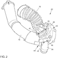
- Fig. 2:
- einen erfindungsgemäßen Verdichter;
- Fig. 3:
- einen Querschnitt durch den Verdichter gemäß der
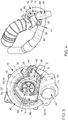
Fig. 2 ; und - Fig. 4:
- eine körperliche Darstellung der von dem Verdichter gemäß den
Fig. 2 und3 ausgebildeten Strömungsräume.
- Fig. 1:
- a schematic representation of an internal combustion engine according to the invention;
- Fig. 2:
- a compressor according to the invention;
- 3:
- a cross section through the compressor according to the
Fig. 2 ; and - 4:
- a physical representation of the compressor according to the
Fig. 2 and3 trained flow spaces.
Die
Das Frischgas wird dem Verbrennungsmotor 10 über einen Frischgasstrang zugeführt und dazu über eine Ansaugmündung 18 aus der Umgebung angesaugt, in einem Luftfilter 20 gereinigt und anschließend in einen erfindungsgemäßen Verdichter 22, der Teil eines erfindungsgemäßen Abgasturboladers ist, geführt. Das Frischgas wird mittels des Verdichters 22 verdichtet, anschließend in einem Ladeluftkühler 24 abgekühlt und den Brennräumen zugeführt. Der Antrieb des Verdichters 22 erfolgt mittels einer Turbine 26 des Abgasturboladers, die in einen Abgasstrang der Brennkraftmaschine integriert ist. Abgas, das bei der Verbrennung des Kraftstoff-Frischgas-Gemisches in den Brennräumen des Verbrennungsmotors 10 entsteht, wird über den Abgasstrang aus dem Verbrennungsmotor 10 abgeführt und durchströmt dabei die Turbine 26. Dies führt in bekannter Weise zu einem rotierenden Antrieb eines Turbinenlaufrads (nicht dargestellt), das über eine Welle 28 drehfest mit einem Verdichterlaufrad 30 (in der
Um im Betrieb des Verbrennungsmotors 10 mit unterschiedlicher Last und unterschiedlichen Drehzahlen eine möglichst optimale Nutzung der Enthalpie des Abgases zur Erzeugung von Verdichtungsleistung mittels des Abgasturboladers realisieren zu können, kann die Turbine 26 des Abgasturboladers optional (insbesondere bei einer Ausgestaltung des Verbrennungsmotors 10 als Dieselmotor) eine mittels der Steuerungsvorrichtung 14 ansteuerbare Vorrichtung zur variablen Turbinenanströmung (VTG) 32 aufweisen. Diese kann in bekannter Weise eine Mehrzahl von in einem Einlass der Turbine 26 angeordnete Leitschaufeln (nicht dargestellt) umfassen, die individuell drehbar ausgebildet sind, wobei diese gemeinsame mittels einer Verstellvorrichtung (nicht dargestellt) verstellbar sind. In Abhängigkeit von den Drehstellungen der Leitschaufeln verengen diese den freien Strömungsquerschnitt in dem Einlass der Turbine 26 mehr oder weniger und beeinflussen zudem den Abschnitt der primären Anströmung des Turbinenlaufrads und die Ausrichtung dieser Anströmung.In order to realize the best possible use of the enthalpy of the exhaust gas by means of the exhaust gas turbocharger during operation of the
Stromab des Verdichters 22 ist in die Ladeluftstrecke, d.h. den Abschnitt des Frischgasstrangs zwischen dem Verdichter 22 und dem Verbrennungsmotor 10, eine ebenfalls mittels der Steuerungsvorrichtung 14 ansteuerbare Regelklappe 34 integriert. Bei einer Ausgestaltung des Verbrennungsmotors 10 als Ottomotor kann es sich bei dieser Regelklappe 34 um eine Drosselklappe (mit bekannter Funktionalität) handeln. Bei einer Ausgestaltung des Verbrennungsmotors 10 als Dieselmotor kann die primäre Funktion der Regelklappe 34 darin bestehen, kurzfristig nach einem Beenden des Betriebs des Dieselmotors die Ladeluftstrecke zu verschließen, wodurch ein Nachströmen von bereits verdichtetem Frischgas in die Brennräume des Dieselmotors und folglich ein sogenanntes "Abstellschütteln" vermieden werden kann. Dadurch soll ein ungewolltes Nachlaufen des Dieselmotors infolge von Selbstzündungen von Kraftstoffresten in den Brennräumen im Beisein von nachgeströmtem Frischgas verhindert werden. Sofern bei einer entsprechenden Brennkraftmaschine auch eine Hochdruck-Abgasrückführung (HD-AGR) vorhanden wäre, könnte die Regelklappe auch zur Beeinflussung und insbesondere Steigerung einer HD-AGR-Rate eingesetzt werden.Downstream of the
Die Brennkraftmaschine umfasst weiterhin eine Niederdruck-Abgasrückführung 50, über die stromab der Turbine 26 ein Teil des durch den Abgasstrang strömenden Abgases abgezweigt und, gesteuert durch einen AGR-Regelventil 52, stromauf des Verdichters 22 in den Frischgasstrang eingeleitet werden kann.The internal combustion engine further comprises a low-pressure exhaust
Die
Der Verdichter 22 umfasst ein ein- oder mehrteiliges Gehäuse 36, das einen Strömungsraum 78 ausbildet, innerhalb dessen ein Verdichterlaufrad 30 drehbar gelagert ist (vgl.
Das Gehäuse 36 des Verdichters 22 bildet weiterhin einen AGR-Kanal 46 aus, der einen AGR-Einlass 48 umfasst, über den der AGR-Kanal 46 an eine Rohrleitung 54 einer Niederdruck-Abgasrückführung 50, beispielsweise der Niederdruck-Abgasrückführung 50 einer Brennkraftmaschine gemäß der
Infolge des bogenförmigen Verlaufs der beiden Teilkanäle 58, 60 des AGR-Kanals 46 wird den zwei über diese Teilkanäle 58, 60 geführten Strömungen 70, 72 rückzuführenden Abgases ein Drall (um den entsprechenden Abschnitt der Längsachse des Einlasskanals 38) aufgezwungen, wobei die Drallrichtung der über den ersten Teilkanal 58 geführten Strömung 70 der vorgesehenen Drehrichtung 64 des Verdichterlaufrads 30 entspricht, während die Drallrichtung der über den zweiten Teilkanal 60 geführten Strömung 72 dieser vorgesehenen Drehrichtung 64 entgegengesetzt ist. Da jedoch der kleinste Strömungsquerschnitt des ersten Teilkanals 58 größer als der kleinste Strömungsquerschnitt des zweiten Teilkanals 60 ist, ist auch derjenige Anteil des insgesamt über den AGR-Kanal 46 strömenden Abgases, der über den ersten Teilkanal 58 bis zu den Sammelabschnitt 66 geführt wird, d.h. der Volumenstrom der Strömung 70, größer als der andere, über den zweiten Teilkanal 60 geführte Anteil, d.h. der Volumenstrom der Strömung 72. Dies führt dazu, dass die Gesamtströmung des rückzuführenden Abgases, die über die AGR-Kanalmündung 68 in den Einlasskanal 38 überströmt, einen Drall aufweist, dessen Drallrichtung der vorgesehenen Drehrichtung 64 des Verdichterlaufrads 30 entspricht. Dieser Drall des in den Einlasskanal 38 rückgeführten Abgases kann sich auf innerhalb des Einlasskanals 38 in Richtung des Verdichterlaufrads 30 strömendes Frischgas übertragen und kann so ein vorteilhaftes Betriebsverhalten des Verdichters 22 unterstützen.As a result of the arcuate course of the two sub-channels 58, 60 of the
Der Einlasskanal 38 weist ausgehend von dem Verdichtereinlass 40 bis hin zu der Mündung in den das Verdichterlaufrad 30 aufnehmenden Strömungsraum 78 einen gekrümmten Verlauf auf. Die AGR-Kanalmündung 68 ist dabei auf der Krümmungsinnenseite dieses gekrümmten Verlaufs angeordnet, wodurch ein dortiger relativer Unterdruck in dem durch den Einlasskanal 38 geführten Frischgas, der sich infolge der gekrümmten Strömungsführung einstellt, ausgenutzt werden kann, um ein Überströmen des rückzuführenden Abgases aus dem AGR-Kanal 46 in den Einlasskanal 38 zu unterstützen.The
Mit Ausnahme der AGR-Kanalmündung 68 ist der Einlasskanal 38 des Verdichters 22 umfangsseitig geschlossen ausgebildet.With the exception of the
- 1010
- Verbrennungsmotorinternal combustion engine
- 1212
- Zylindercylinder
- 1414
- Steuerungsvorrichtungcontrol device
- 1616
- Injektorinjector
- 1818
- Ansaugmündungsuction port
- 2020
- Luftfilterair filter
- 2222
- Verdichtercompressor
- 2424
- LadeluftkühlerIntercooler
- 2626
- Turbineturbine
- 2828
- Wellewave
- 3030
- Verdichterlaufradcompressor impeller
- 3232
- Vorrichtung zur variablen TurbinenanströmungVariable turbine inlet device
- 3434
- Regelklappecontrol flap
- 3636
- Gehäuse des VerdichtersHousing of the compressor
- 3838
- Einlasskanal des VerdichtersInlet channel of the compressor
- 4040
- Verdichtereinlasscompressor inlet
- 4242
- VerdichtervoluteVerdichtervolute
- 4444
- Verdichterauslasscompressor outlet
- 4646
- AGR-KanalEGR passage
- 4848
- AGR-EinlassEGR inlet
- 5050
- Niederdruck-AbgasrückführungLow-pressure exhaust gas recirculation
- 5252
- AGR-RegelventilEGR control valve
- 5454
- Rohrleitung einer Niederdruck-AbgasrückführungPipeline of a low pressure exhaust gas recirculation
- 5656
- Anfangsabschnitt des AGR-KanalsBeginning section of the EGR channel
- 5858
- erster Teilkanal des AGR-Kanalsfirst sub-channel of the EGR channel
- 6060
- zweiter Teilkanal des AGR-Kanalssecond sub-channel of the EGR channel
- 6262
- AGR-KanalabschnittseinlassEGR passage portion inlet
- 6464
- vorgesehene Drehrichtung des Verdichterlaufradsintended direction of rotation of the compressor impeller
- 6666
- Sammelabschnitt des AGR-KanalsCollection section of the EGR channel
- 6868
- AGR-KanalmündungEGR duct opening
- 7070
- Strömung von über den ersten Teilkanal rückzuführendem AbgasFlow of exhaust gas to be recirculated via the first subchannel
- 7272
- Strömung von über den zweiten Teilkanal rückzuführendem AbgasFlow of exhaust gas to be recirculated via the second subchannel
- 7474
- AGR-KanalabschnittEGR passage section
- 7676
- Rohrleitungpipeline
- 7878
- Strömungsraumflow chamber
- α:α:
- Umfangsbreite der AGR-KanalmündungCircumferential width of the EGR duct mouth
- α':α ':
- Umfangsmitte der AGR-KanalmündungCenter of circumference of the EGR duct mouth
- β:β:
- Umfangsbreite des AGR-KanalabschnittseinlassesCircumferential width of the EGR duct section inlet
- β':β ':
- Umfangsmitte des AGR- KanaleinlassesCenter of circumference of the EGR duct inlet
Claims (6)
- Compressor (22) having a housing (36) which forms a flow chamber (78), within which a compressor impeller (30) is rotatably mounted, and an inlet channel (38), which extends between a compressor inlet (40) and the flow chamber (78), wherein an EGR channel (46) for exhaust-gas recirculation opens into the inlet channel (38), wherein the EGR channel (46), in an EGR channel portion (74) of circumferentially closed form, runs in arcuate fashion around at least one portion of the circumference of the inlet channel (38), such that an EGR channel portion inlet (62) is arranged offset relative to the EGR channel mouth (68) in the circumferential direction of the inlet channel (38), and wherein the EGR channel (46) is formed such that exhaust gas entering the inlet channel (38) via the EGR channel (46) exhibits swirl in the direction of rotation (64) intended for the compressor impeller (30), characterized in that the EGR channel portion (74) comprises two partial channels (58, 60) which, proceeding from the EGR channel portion inlet (62), run in opposite circumferential directions around at least one portion of the circumference of the inlet channel (38), wherein the smallest flow cross section of that partial channel (58) whose curvature direction corresponds to the direction of rotation (64) intended for the compressor impeller (30) is larger than the smallest flow cross section of the other partial channel (60).
- Compressor (22) according to Claim 1, characterized in that the EGR channel portion (74) runs around at least 90°, 120° or 150° of the circumference of the inlet channel (38).
- Compressor (22) according to any of the preceding claims, characterized in that the inlet channel (38) has a curved profile, and the EGR channel mouth (68) is arranged on the inner side of the curve.
- Compressor (22) according to any of the preceding claims, characterized in that the inlet channel (38) is formed so as to be circumferentially closed with the exception of the EGR channel mouth (68) .
- Exhaust-gas turbocharger having a compressor (22) according to any of the preceding claims and having a turbine (26) which has a turbine impeller mounted rotatably in a housing, wherein the turbine impeller is connected with rotational driving action to the compressor impeller (30).
- Combustion machine having an internal combustion engine (10), a fresh-gas tract, an exhaust-gas tract, a low-pressure exhaust gas recirculation arrangement and a compressor (22) according to any of Claims 1 to 4 integrated into the fresh-gas tract, or an exhaust-gas turbocharger according to Claim 5, wherein the compressor (22) is integrated into the fresh-gas tract.
Applications Claiming Priority (1)
| Application Number | Priority Date | Filing Date | Title |
|---|---|---|---|
| DE102016207948.4A DE102016207948A1 (en) | 2016-05-09 | 2016-05-09 | Compressor, exhaust gas turbocharger and internal combustion engine |
Publications (2)
| Publication Number | Publication Date |
|---|---|
| EP3244035A1 EP3244035A1 (en) | 2017-11-15 |
| EP3244035B1 true EP3244035B1 (en) | 2019-05-08 |
Family
ID=58454863
Family Applications (1)
| Application Number | Title | Priority Date | Filing Date |
|---|---|---|---|
| EP17162834.0A Active EP3244035B1 (en) | 2016-05-09 | 2017-03-24 | Compressor, exhaust gas turbocharger and combustion engine |
Country Status (2)
| Country | Link |
|---|---|
| EP (1) | EP3244035B1 (en) |
| DE (1) | DE102016207948A1 (en) |
Families Citing this family (3)
| Publication number | Priority date | Publication date | Assignee | Title |
|---|---|---|---|---|
| CN108104986B (en) * | 2017-12-27 | 2023-12-15 | 潍柴动力股份有限公司 | Engine and mixed air inlet device thereof |
| US11408362B2 (en) * | 2018-08-28 | 2022-08-09 | Borgwarner Inc. | High efficiency turbocharger with EGR system |
| DE102020105814A1 (en) | 2020-03-04 | 2021-09-09 | Volkswagen Aktiengesellschaft | Compressor and motor vehicle with one |
Citations (1)
| Publication number | Priority date | Publication date | Assignee | Title |
|---|---|---|---|---|
| EP2987983A1 (en) * | 2013-04-16 | 2016-02-24 | Toyota Jidosha Kabushiki Kaisha | Compressor for exhaust-gas turbo-supercharger |
Family Cites Families (9)
| Publication number | Priority date | Publication date | Assignee | Title |
|---|---|---|---|---|
| DE102004040893A1 (en) | 2004-08-24 | 2006-03-02 | Bayerische Motoren Werke Ag | turbocharger |
| US7204241B2 (en) * | 2004-08-30 | 2007-04-17 | Honeywell International, Inc. | Compressor stage separation system |
| KR101741625B1 (en) * | 2010-09-02 | 2017-05-30 | 보르그워너 인코퍼레이티드 | Compressor recirculation into annular volume |
| DE102011117360A1 (en) | 2011-10-29 | 2013-05-02 | Volkswagen Ag | Gas supply system i.e. exhaust gas recirculation system, for guiding gas to flow of another gas in internal combustion engine of e.g. lorry, has pipeline connected with another pipeline by inlet that is realized by annular gap |
| DE102012013595B4 (en) | 2012-07-07 | 2023-03-16 | Volkswagen Aktiengesellschaft | Internal combustion engine and method for operating an internal combustion engine |
| US9303650B2 (en) * | 2013-06-24 | 2016-04-05 | Ford Global Technologies, Llc | Introduction of exhaust gas recirculation at a compressor blade trailing edge |
| JP6056748B2 (en) * | 2013-12-20 | 2017-01-11 | トヨタ自動車株式会社 | Supercharged engine EGR system |
| GB2526594A (en) * | 2014-05-29 | 2015-12-02 | Gm Global Tech Operations Inc | A device for connecting an exhaust gas recirculation conduit to an intake pipe |
| DE102014216162B4 (en) * | 2014-08-14 | 2019-01-17 | Ford Global Technologies, Llc | Charged internal combustion engine with exhaust gas turbocharger and method for operating such an internal combustion engine |
-
2016
- 2016-05-09 DE DE102016207948.4A patent/DE102016207948A1/en not_active Withdrawn
-
2017
- 2017-03-24 EP EP17162834.0A patent/EP3244035B1/en active Active
Patent Citations (1)
| Publication number | Priority date | Publication date | Assignee | Title |
|---|---|---|---|---|
| EP2987983A1 (en) * | 2013-04-16 | 2016-02-24 | Toyota Jidosha Kabushiki Kaisha | Compressor for exhaust-gas turbo-supercharger |
Also Published As
| Publication number | Publication date |
|---|---|
| DE102016207948A1 (en) | 2017-11-09 |
| EP3244035A1 (en) | 2017-11-15 |
Similar Documents
| Publication | Publication Date | Title |
|---|---|---|
| DE10116643C2 (en) | reciprocating internal combustion engine | |
| EP3141735B1 (en) | Combusion engine with booster | |
| DE102006019780A1 (en) | Exhaust gas turbocharger in an internal combustion engine | |
| DE102004035044A1 (en) | Compressor in an exhaust gas turbocharger for an internal combustion engine and method for operating a compressor | |
| DE10212675A1 (en) | Exhaust gas turbocharger in an internal combustion engine | |
| DE112012002727T5 (en) | Turbocharged turbocharged turbine and associated engine and method | |
| DE102004030703A1 (en) | Exhaust gas turbocharger for a reciprocating internal combustion engine and reciprocating internal combustion engine | |
| DE112011100573T5 (en) | TURBOCHARGER | |
| EP3542069A1 (en) | Compressor, exhaust gas turbocharger and internal combustion engine | |
| EP3244035B1 (en) | Compressor, exhaust gas turbocharger and combustion engine | |
| DE10329019A1 (en) | Internal combustion engine with a compressor in the intake system and method for this purpose | |
| DE19540060A1 (en) | Engine brake device | |
| DE102012212076A1 (en) | HOUSING ASSEMBLY FOR AIR CHARGING SYSTEM | |
| DE102014212606B4 (en) | Motor vehicle and air filter box | |
| EP3591185A1 (en) | Method for operating a combustion engine with a trim adjuster assigned to the compressor | |
| DE102012013595B4 (en) | Internal combustion engine and method for operating an internal combustion engine | |
| EP3591186B1 (en) | Method for operating a combustion engine with a trim adjuster assigned to the compressor | |
| DE102011111747A1 (en) | Compressor for exhaust turbocharger of internal combustion engine, particularly gasoline engine of motor vehicle, particularly passenger car, comprises guide element arranged against air flow in axial direction of compressor wheel | |
| DE102007021934A1 (en) | Supercharger unit for internal combustion engine, has compressor wheel, which has multiple blades for combustion air intake, which are arranged on hub of the compressor wheel | |
| DE102014220680A1 (en) | Internal combustion engine with mixed-flow turbine comprising a guide | |
| DE102016112030B4 (en) | Compressor, exhaust gas turbocharger and internal combustion engine | |
| DE102012006673B4 (en) | Compressor for an exhaust gas turbocharger, in particular a motor vehicle | |
| DE102017200060B4 (en) | Internal combustion engine and compressor | |
| DE102017218295B4 (en) | Compressor for a turbocharger of an internal combustion engine and a turbocharger for an internal combustion engine | |
| DE102006027738A1 (en) | Internal-combustion engine, has low pressure and high pressure compressors that are switched into, where one of compressors is rotatably coupled with exhaust-gas turbine, and overflow unit provided between intake system and exhaust tract |
Legal Events
| Date | Code | Title | Description |
|---|---|---|---|
| PUAI | Public reference made under article 153(3) epc to a published international application that has entered the european phase |
Free format text: ORIGINAL CODE: 0009012 |
|
| STAA | Information on the status of an ep patent application or granted ep patent |
Free format text: STATUS: THE APPLICATION HAS BEEN PUBLISHED |
|
| AK | Designated contracting states |
Kind code of ref document: A1 Designated state(s): AL AT BE BG CH CY CZ DE DK EE ES FI FR GB GR HR HU IE IS IT LI LT LU LV MC MK MT NL NO PL PT RO RS SE SI SK SM TR |
|
| AX | Request for extension of the european patent |
Extension state: BA ME |
|
| STAA | Information on the status of an ep patent application or granted ep patent |
Free format text: STATUS: REQUEST FOR EXAMINATION WAS MADE |
|
| 17P | Request for examination filed |
Effective date: 20180515 |
|
| RBV | Designated contracting states (corrected) |
Designated state(s): AL AT BE BG CH CY CZ DE DK EE ES FI FR GB GR HR HU IE IS IT LI LT LU LV MC MK MT NL NO PL PT RO RS SE SI SK SM TR |
|
| STAA | Information on the status of an ep patent application or granted ep patent |
Free format text: STATUS: EXAMINATION IS IN PROGRESS |
|
| 17Q | First examination report despatched |
Effective date: 20180904 |
|
| GRAP | Despatch of communication of intention to grant a patent |
Free format text: ORIGINAL CODE: EPIDOSNIGR1 |
|
| STAA | Information on the status of an ep patent application or granted ep patent |
Free format text: STATUS: GRANT OF PATENT IS INTENDED |
|
| INTG | Intention to grant announced |
Effective date: 20190103 |
|
| GRAS | Grant fee paid |
Free format text: ORIGINAL CODE: EPIDOSNIGR3 |
|
| GRAA | (expected) grant |
Free format text: ORIGINAL CODE: 0009210 |
|
| STAA | Information on the status of an ep patent application or granted ep patent |
Free format text: STATUS: THE PATENT HAS BEEN GRANTED |
|
| AK | Designated contracting states |
Kind code of ref document: B1 Designated state(s): AL AT BE BG CH CY CZ DE DK EE ES FI FR GB GR HR HU IE IS IT LI LT LU LV MC MK MT NL NO PL PT RO RS SE SI SK SM TR |
|
| REG | Reference to a national code |
Ref country code: GB Ref legal event code: FG4D Free format text: NOT ENGLISH |
|
| REG | Reference to a national code |
Ref country code: CH Ref legal event code: EP Ref country code: AT Ref legal event code: REF Ref document number: 1130452 Country of ref document: AT Kind code of ref document: T Effective date: 20190515 |
|
| REG | Reference to a national code |
Ref country code: DE Ref legal event code: R096 Ref document number: 502017001262 Country of ref document: DE |
|
| REG | Reference to a national code |
Ref country code: IE Ref legal event code: FG4D Free format text: LANGUAGE OF EP DOCUMENT: GERMAN |
|
| REG | Reference to a national code |
Ref country code: NL Ref legal event code: MP Effective date: 20190508 |
|
| REG | Reference to a national code |
Ref country code: LT Ref legal event code: MG4D |
|
| PG25 | Lapsed in a contracting state [announced via postgrant information from national office to epo] |
Ref country code: LT Free format text: LAPSE BECAUSE OF FAILURE TO SUBMIT A TRANSLATION OF THE DESCRIPTION OR TO PAY THE FEE WITHIN THE PRESCRIBED TIME-LIMIT Effective date: 20190508 Ref country code: HR Free format text: LAPSE BECAUSE OF FAILURE TO SUBMIT A TRANSLATION OF THE DESCRIPTION OR TO PAY THE FEE WITHIN THE PRESCRIBED TIME-LIMIT Effective date: 20190508 Ref country code: NL Free format text: LAPSE BECAUSE OF FAILURE TO SUBMIT A TRANSLATION OF THE DESCRIPTION OR TO PAY THE FEE WITHIN THE PRESCRIBED TIME-LIMIT Effective date: 20190508 Ref country code: SE Free format text: LAPSE BECAUSE OF FAILURE TO SUBMIT A TRANSLATION OF THE DESCRIPTION OR TO PAY THE FEE WITHIN THE PRESCRIBED TIME-LIMIT Effective date: 20190508 Ref country code: NO Free format text: LAPSE BECAUSE OF FAILURE TO SUBMIT A TRANSLATION OF THE DESCRIPTION OR TO PAY THE FEE WITHIN THE PRESCRIBED TIME-LIMIT Effective date: 20190808 Ref country code: ES Free format text: LAPSE BECAUSE OF FAILURE TO SUBMIT A TRANSLATION OF THE DESCRIPTION OR TO PAY THE FEE WITHIN THE PRESCRIBED TIME-LIMIT Effective date: 20190508 Ref country code: AL Free format text: LAPSE BECAUSE OF FAILURE TO SUBMIT A TRANSLATION OF THE DESCRIPTION OR TO PAY THE FEE WITHIN THE PRESCRIBED TIME-LIMIT Effective date: 20190508 Ref country code: PT Free format text: LAPSE BECAUSE OF FAILURE TO SUBMIT A TRANSLATION OF THE DESCRIPTION OR TO PAY THE FEE WITHIN THE PRESCRIBED TIME-LIMIT Effective date: 20190908 Ref country code: FI Free format text: LAPSE BECAUSE OF FAILURE TO SUBMIT A TRANSLATION OF THE DESCRIPTION OR TO PAY THE FEE WITHIN THE PRESCRIBED TIME-LIMIT Effective date: 20190508 |
|
| PG25 | Lapsed in a contracting state [announced via postgrant information from national office to epo] |
Ref country code: BG Free format text: LAPSE BECAUSE OF FAILURE TO SUBMIT A TRANSLATION OF THE DESCRIPTION OR TO PAY THE FEE WITHIN THE PRESCRIBED TIME-LIMIT Effective date: 20190808 Ref country code: GR Free format text: LAPSE BECAUSE OF FAILURE TO SUBMIT A TRANSLATION OF THE DESCRIPTION OR TO PAY THE FEE WITHIN THE PRESCRIBED TIME-LIMIT Effective date: 20190809 Ref country code: LV Free format text: LAPSE BECAUSE OF FAILURE TO SUBMIT A TRANSLATION OF THE DESCRIPTION OR TO PAY THE FEE WITHIN THE PRESCRIBED TIME-LIMIT Effective date: 20190508 Ref country code: RS Free format text: LAPSE BECAUSE OF FAILURE TO SUBMIT A TRANSLATION OF THE DESCRIPTION OR TO PAY THE FEE WITHIN THE PRESCRIBED TIME-LIMIT Effective date: 20190508 |
|
| PG25 | Lapsed in a contracting state [announced via postgrant information from national office to epo] |
Ref country code: SK Free format text: LAPSE BECAUSE OF FAILURE TO SUBMIT A TRANSLATION OF THE DESCRIPTION OR TO PAY THE FEE WITHIN THE PRESCRIBED TIME-LIMIT Effective date: 20190508 Ref country code: CZ Free format text: LAPSE BECAUSE OF FAILURE TO SUBMIT A TRANSLATION OF THE DESCRIPTION OR TO PAY THE FEE WITHIN THE PRESCRIBED TIME-LIMIT Effective date: 20190508 Ref country code: RO Free format text: LAPSE BECAUSE OF FAILURE TO SUBMIT A TRANSLATION OF THE DESCRIPTION OR TO PAY THE FEE WITHIN THE PRESCRIBED TIME-LIMIT Effective date: 20190508 Ref country code: DK Free format text: LAPSE BECAUSE OF FAILURE TO SUBMIT A TRANSLATION OF THE DESCRIPTION OR TO PAY THE FEE WITHIN THE PRESCRIBED TIME-LIMIT Effective date: 20190508 Ref country code: EE Free format text: LAPSE BECAUSE OF FAILURE TO SUBMIT A TRANSLATION OF THE DESCRIPTION OR TO PAY THE FEE WITHIN THE PRESCRIBED TIME-LIMIT Effective date: 20190508 |
|
| REG | Reference to a national code |
Ref country code: DE Ref legal event code: R097 Ref document number: 502017001262 Country of ref document: DE |
|
| PG25 | Lapsed in a contracting state [announced via postgrant information from national office to epo] |
Ref country code: SM Free format text: LAPSE BECAUSE OF FAILURE TO SUBMIT A TRANSLATION OF THE DESCRIPTION OR TO PAY THE FEE WITHIN THE PRESCRIBED TIME-LIMIT Effective date: 20190508 Ref country code: IT Free format text: LAPSE BECAUSE OF FAILURE TO SUBMIT A TRANSLATION OF THE DESCRIPTION OR TO PAY THE FEE WITHIN THE PRESCRIBED TIME-LIMIT Effective date: 20190508 |
|
| PLBE | No opposition filed within time limit |
Free format text: ORIGINAL CODE: 0009261 |
|
| STAA | Information on the status of an ep patent application or granted ep patent |
Free format text: STATUS: NO OPPOSITION FILED WITHIN TIME LIMIT |
|
| PG25 | Lapsed in a contracting state [announced via postgrant information from national office to epo] |
Ref country code: TR Free format text: LAPSE BECAUSE OF FAILURE TO SUBMIT A TRANSLATION OF THE DESCRIPTION OR TO PAY THE FEE WITHIN THE PRESCRIBED TIME-LIMIT Effective date: 20190508 |
|
| 26N | No opposition filed |
Effective date: 20200211 |
|
| PG25 | Lapsed in a contracting state [announced via postgrant information from national office to epo] |
Ref country code: PL Free format text: LAPSE BECAUSE OF FAILURE TO SUBMIT A TRANSLATION OF THE DESCRIPTION OR TO PAY THE FEE WITHIN THE PRESCRIBED TIME-LIMIT Effective date: 20190508 |
|
| PG25 | Lapsed in a contracting state [announced via postgrant information from national office to epo] |
Ref country code: SI Free format text: LAPSE BECAUSE OF FAILURE TO SUBMIT A TRANSLATION OF THE DESCRIPTION OR TO PAY THE FEE WITHIN THE PRESCRIBED TIME-LIMIT Effective date: 20190508 |
|
| PG25 | Lapsed in a contracting state [announced via postgrant information from national office to epo] |
Ref country code: MC Free format text: LAPSE BECAUSE OF FAILURE TO SUBMIT A TRANSLATION OF THE DESCRIPTION OR TO PAY THE FEE WITHIN THE PRESCRIBED TIME-LIMIT Effective date: 20190508 |
|
| REG | Reference to a national code |
Ref country code: CH Ref legal event code: PL |
|
| REG | Reference to a national code |
Ref country code: BE Ref legal event code: MM Effective date: 20200331 |
|
| PG25 | Lapsed in a contracting state [announced via postgrant information from national office to epo] |
Ref country code: LU Free format text: LAPSE BECAUSE OF NON-PAYMENT OF DUE FEES Effective date: 20200324 |
|
| PG25 | Lapsed in a contracting state [announced via postgrant information from national office to epo] |
Ref country code: CH Free format text: LAPSE BECAUSE OF NON-PAYMENT OF DUE FEES Effective date: 20200331 Ref country code: LI Free format text: LAPSE BECAUSE OF NON-PAYMENT OF DUE FEES Effective date: 20200331 Ref country code: FR Free format text: LAPSE BECAUSE OF NON-PAYMENT OF DUE FEES Effective date: 20200331 Ref country code: IE Free format text: LAPSE BECAUSE OF NON-PAYMENT OF DUE FEES Effective date: 20200324 |
|
| PG25 | Lapsed in a contracting state [announced via postgrant information from national office to epo] |
Ref country code: BE Free format text: LAPSE BECAUSE OF NON-PAYMENT OF DUE FEES Effective date: 20200331 |
|
| GBPC | Gb: european patent ceased through non-payment of renewal fee |
Effective date: 20210324 |
|
| PG25 | Lapsed in a contracting state [announced via postgrant information from national office to epo] |
Ref country code: GB Free format text: LAPSE BECAUSE OF NON-PAYMENT OF DUE FEES Effective date: 20210324 |
|
| PG25 | Lapsed in a contracting state [announced via postgrant information from national office to epo] |
Ref country code: MT Free format text: LAPSE BECAUSE OF FAILURE TO SUBMIT A TRANSLATION OF THE DESCRIPTION OR TO PAY THE FEE WITHIN THE PRESCRIBED TIME-LIMIT Effective date: 20190508 Ref country code: CY Free format text: LAPSE BECAUSE OF FAILURE TO SUBMIT A TRANSLATION OF THE DESCRIPTION OR TO PAY THE FEE WITHIN THE PRESCRIBED TIME-LIMIT Effective date: 20190508 |
|
| PG25 | Lapsed in a contracting state [announced via postgrant information from national office to epo] |
Ref country code: MK Free format text: LAPSE BECAUSE OF FAILURE TO SUBMIT A TRANSLATION OF THE DESCRIPTION OR TO PAY THE FEE WITHIN THE PRESCRIBED TIME-LIMIT Effective date: 20190508 Ref country code: IS Free format text: LAPSE BECAUSE OF FAILURE TO SUBMIT A TRANSLATION OF THE DESCRIPTION OR TO PAY THE FEE WITHIN THE PRESCRIBED TIME-LIMIT Effective date: 20190908 |
|
| REG | Reference to a national code |
Ref country code: AT Ref legal event code: MM01 Ref document number: 1130452 Country of ref document: AT Kind code of ref document: T Effective date: 20220324 |
|
| PGFP | Annual fee paid to national office [announced via postgrant information from national office to epo] |
Ref country code: DE Payment date: 20230331 Year of fee payment: 7 |
|
| P01 | Opt-out of the competence of the unified patent court (upc) registered |
Effective date: 20230523 |
|
| PG25 | Lapsed in a contracting state [announced via postgrant information from national office to epo] |
Ref country code: AT Free format text: LAPSE BECAUSE OF NON-PAYMENT OF DUE FEES Effective date: 20220324 |