EP1880930A1 - Isothermbehälter für ein Fahrzeug - Google Patents
Isothermbehälter für ein Fahrzeug Download PDFInfo
- Publication number
- EP1880930A1 EP1880930A1 EP07356040A EP07356040A EP1880930A1 EP 1880930 A1 EP1880930 A1 EP 1880930A1 EP 07356040 A EP07356040 A EP 07356040A EP 07356040 A EP07356040 A EP 07356040A EP 1880930 A1 EP1880930 A1 EP 1880930A1
- Authority
- EP
- European Patent Office
- Prior art keywords
- door
- edge
- profile
- opening
- insulated
- Prior art date
- Legal status (The legal status is an assumption and is not a legal conclusion. Google has not performed a legal analysis and makes no representation as to the accuracy of the status listed.)
- Granted
Links
- 238000013016 damping Methods 0.000 claims abstract description 7
- 230000035939 shock Effects 0.000 claims description 11
- 238000010521 absorption reaction Methods 0.000 claims description 5
- 230000002093 peripheral effect Effects 0.000 claims description 4
- 239000011324 bead Substances 0.000 claims description 3
- 230000003014 reinforcing effect Effects 0.000 claims description 3
- 238000009432 framing Methods 0.000 claims 1
- 238000003032 molecular docking Methods 0.000 description 6
- 239000002184 metal Substances 0.000 description 5
- 230000008901 benefit Effects 0.000 description 4
- 230000000694 effects Effects 0.000 description 4
- 230000004224 protection Effects 0.000 description 3
- 238000011084 recovery Methods 0.000 description 3
- 239000010868 animal carcass Substances 0.000 description 2
- 238000010276 construction Methods 0.000 description 2
- 238000009413 insulation Methods 0.000 description 2
- 229920002635 polyurethane Polymers 0.000 description 2
- 239000004814 polyurethane Substances 0.000 description 2
- 230000002787 reinforcement Effects 0.000 description 2
- 241001531957 Opsariichthys uncirostris Species 0.000 description 1
- 230000006399 behavior Effects 0.000 description 1
- 230000009286 beneficial effect Effects 0.000 description 1
- 230000000593 degrading effect Effects 0.000 description 1
- 230000009977 dual effect Effects 0.000 description 1
- 229920001971 elastomer Polymers 0.000 description 1
- 239000011810 insulating material Substances 0.000 description 1
- 238000000034 method Methods 0.000 description 1
- 238000005057 refrigeration Methods 0.000 description 1
- 230000004044 response Effects 0.000 description 1
- 238000007789 sealing Methods 0.000 description 1
- 238000004904 shortening Methods 0.000 description 1
- 125000006850 spacer group Chemical group 0.000 description 1
Images


Classifications
-
- B—PERFORMING OPERATIONS; TRANSPORTING
- B62—LAND VEHICLES FOR TRAVELLING OTHERWISE THAN ON RAILS
- B62D—MOTOR VEHICLES; TRAILERS
- B62D33/00—Superstructures for load-carrying vehicles
- B62D33/04—Enclosed load compartments ; Frameworks for movable panels, tarpaulins or side curtains
- B62D33/048—Enclosed load compartments ; Frameworks for movable panels, tarpaulins or side curtains for refrigerated goods vehicles
-
- B—PERFORMING OPERATIONS; TRANSPORTING
- B60—VEHICLES IN GENERAL
- B60P—VEHICLES ADAPTED FOR LOAD TRANSPORTATION OR TO TRANSPORT, TO CARRY, OR TO COMPRISE SPECIAL LOADS OR OBJECTS
- B60P3/00—Vehicles adapted to transport, to carry or to comprise special loads or objects
- B60P3/20—Refrigerated goods vehicles
Definitions
- the present invention relates to an insulated body for a motorized vehicle or for a non-motorized vehicle of the trailer or semi-trailer type.
- a refrigerated vehicle comprises an insulated box composed of insulating panels that can use the polyurethane sandwich technique. These insulated boxes can take place on a carrier chassis of a vehicle or on a chassis or pseudo chassis semi-trailer.
- the logistics of cold products impose specific constraints to ensure the continuity of the cold chain.
- the repetition and the brutality of the berths can damage the box with as a consequence costs of repairing the box and immobilization of it during the repair operations.
- isothermal transport Another specificity of isothermal transport is that some products can be hung on rails which are themselves fixed in height of the body. Animal carcasses are typically transported in this manner. This creates significant mechanical stresses, especially in torsion around the longitudinal axis of the body; these stresses tend to deform the body in the form of a parallelogram around its longitudinal axis; especially when the vehicle is part of a curve the suspended loads in the box undergo a centrifugal force which creates a moment around the axis longitudinal of the body. The side walls of the box can then tilt relative to the floor, giving the box a form of parallelogram.
- the present invention aims to remedy these disadvantages.
- An object of the invention is to provide an insulated box that can be loaded on a vehicle capable of supporting repeated dockings with a handling dock.
- Another object of the invention is to provide an insulated body capable of supporting repeated berthing while improving the torsional rigidity of the body.
- the present invention relates to a parallelepiped isothermal box that can be placed on a chassis of a motorized or non-motorized vehicle;
- the insulated box consists of insulating panels forming a front wall, a floor, a ceiling, and two side walls flanking a rear opening which is closed by at least one door;
- the box further comprises means for connecting each of the doors to the edge of each side panel for pivoting each door from (i) the connecting means delimit a cavity which extends along the edge of each side wall in which is disposed a shock absorbing member at (ii) an open position in which each door is folded against the outer face of the side walls and is offset longitudinally towards the front wall of the body.
- An essential aspect of the invention is the consideration of the problem of docking and the resulting impacts on the insulated body of a refrigerated vehicle.
- the invention is characterized by the presence of connecting means which provide a dual function. On the one hand, it is the creation of a cavity at the end of each side wall of the body; this cavity receives a shock absorbing member which provides protection for an insulated body part which is traditionally exposed to shocks. On the other hand, it is to deport, out of the berthing zone, the door when it is in the open position.
- a further benefit of the invention lies in the particularly smooth appearance of the rear face of the body, since it is the opening profile which is the main visible part of the connection between the door and the side walls.
- each door engages at least partially in the box and is equipped with stiffening means opposing the torsion deformation of the box and / or setting parallelogram of the latter with respect to its longitudinal axis.
- This other provision of the invention improves the torsional behavior of the body. Because of its length (up to nearly 14 meters), the body is stressed in torsion significantly. By interlocking each door in the box and reinforcing each of the doors, they ensure a recovery of the forces exerted on the walls of the box and thus contribute to increase the rigidity. This provision whose stiffening effect is added to the conventional closing linkage of each door contributes to combat very effectively parallelogram deformation of the body.
- each door at at least one of its corners, may have a stiffening insert that opposes the torsional deformation of the body and / or parallelism of the latter with respect to its longitudinal axis.
- stiffening insert has a positioning circumscribed to the zones of the door which have a maximum effect on the transfer of forces; the stiffening insert thus interferes little with the general insulation of the door. Thanks to the stiffening inserts, the body is substantially less prone to possible deformations parallelogram.
- each door has at least one stiffening insert positioned in the angle thereof adjacent to the angle of the rear opening intersecting the floor and one of the side walls.
- each door is equipped with a stiffening insert in the lower part.
- each door has two stiffening inserts positioned in its two lateral angles.
- This provision which provides that each door is equipped with two stiffening inserts in its side angles is extremely relevant because it allows to work the stiffening inserts two by two along the two diagonals of the rear face. If we consider the two fictitious diagonals that start from the corners of the rear opening of the body, we can see that thanks to the stiffening inserts that fit into each of the corners of the rear opening, these two diagonals remain stable even when the body is stressed in torsion.
- the parallelogram of the body which results in an elongation of one of the diagonals and the shortening of the other diagonal is very substantially limited by the presence of stiffening inserts.
- Another notable effect of the presence of the stiffening inserts, in particular, the inserts located at the lower side angles is a reinforcement against shocks that can be exerted on the lower part of one of the doors.
- each door has a reinforcing frame encircling an insulating panel on which is supported the stiffening insert.
- the stiffening insert may comprise two plates respectively bonded to the inner faces of the internal walls forming a rear door.
- each of the doors can be connected to the body by two to four double knuckle hinges.
- each door carries a peripheral seal with several lips that crash against the inner walls of the body when said door is in the closed position.
- the opening profile has a rib on which is shod a seal which abuts against the edge located at the intersection of the inner face and the edge of a side wall.
- a damping bead is arranged on the edge of the floor.
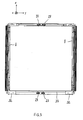
- the insulated box 1 in its embodiment illustrated in the drawing is described with respect to a reference xyz (see Figure 1) having a longitudinal direction x by the term “length”, “front”, “rear”, a transverse direction y with respect to which the terms “width”, “lateral” and a vertical direction z, in relation to which, the terms “higher”, “lower”, “height” are used in particular.
- the body which bears the general reference 1 comprises a front wall (which does not appear in Figure 1) a floor 3, a ceiling 5, and two side walls 4 parallel.
- the two side walls 4 frame a rear opening that allows loading and unloading; this opening is closed by two doors 6 which are respectively articulated on each of the side walls 4.
- the floor 3, ceiling 5, side walls 4 and front wall are made of insulating panels that can be polyurethane sandwich.
- the body 1 generally includes a refrigeration unit that can be suspended on its front wall.
- the body 1 is placed and fixed on a vehicle chassis; in the example shown it is a semi-trailer chassis with two axles intended to be towed by a towing vehicle, but it may be said that the body 1 could very well be placed on a chassis of a truck.
- one of the quite specific points of the body according to the invention lies in the realization of the articulation on each of the two side walls 4 of the two doors 6 which close the opening of the body 1.
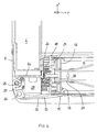
- Figure 5 shows, in section, an embodiment of this functional link.
- FIG. 5 represents a partial cross-section of a side wall 4 and a door 6 fixed on this wall 4 by means of connection specific to the invention which will now be described.
- the side wall 4, just like the door 6, have a substantial thickness, which allows them to achieve good insulation of the body.
- a sleep profile 8 which, in cross section, has substantially the shape of a U; a hollow rib 9 is contiguous to the U-shaped portion of the frame profile 8 and runs over the entire height of the latter. As can be seen in Figure 5, the rib 9 is pierced with a bore which extends over its entire height.
- the frame profile 8 has four cutouts in the hollow rib 9 whose function will appear later.
- hollow rib 9 is located substantially at the intersection of the outer face 4a of the side wall 4 and its edge 4b.
- the door 6 receives an opening section 12 which is substantially in cross section, in the form of a wing 13 whose end has a hem 14 in which is formed a bore and whose other end has two attachment flanges 15 and 16 perpendicular to each other.
- the door 6 is provided with a peripheral frame 18 which can be made of rigid insulating material (for example PVC or PE) and which surrounds the insulating panel constituting the door 6; it is on this frame 18 that the opening profile 12 is fixed. It can be seen in FIG. 5 one of the fixing screws 17 which can secure the opening profile 12 to the door 6.
- a peripheral frame 18 which can be made of rigid insulating material (for example PVC or PE) and which surrounds the insulating panel constituting the door 6; it is on this frame 18 that the opening profile 12 is fixed. It can be seen in FIG. 5 one of the fixing screws 17 which can secure the opening profile 12 to the door 6.
- the door 6 is provided with several seals which come to seal with the inner face of the side wall 4.
- These seals can be, for example as can be seen in Figure 5, a seal sealing ring 19 with three lips 20 which is engaged by a pin 21 against undercutting in the peripheral frame 18 of the door 6.
- It may also be provided to provide the opening profile 12 with a rib 23 on which is to be fitted a seal 24 which will come into contact with the edge of the fixed profile 8 when the door 6 is closed.
- the opening section 12 has four cuts made in its hem portion 14.
- each of these double knuckle hinges consists of a metal part which has two parallel bores in which connecting rods 26 are engaged.
- the connecting rods 26 are telescopic rods which are embedded in each of the hinges as appears in particular in Figure 8.
- Other connecting means can be envisaged; it may, for example, be envisaged to provide the box 1 with rods which extend over the entire height of the side wall 4.
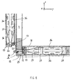
- each of the doors 6 is done through a rod operable by a handle 30 embedded in the surface of the door 6 and which is engaged or disengaged from a strike 27 metal reported on the edge of the floor 3 and on the song of the ceiling 5.
- the body 1 may have additional shock absorption means such as bumpers 32 positioned at each end of the floor 3 and a bead 33 running along the edge of the floor 3.
- the absorption means of shocks can also be arranged on the frame that supports the body 1 in vertical or horizontal orientations.
- FIG. 5 illustrates a first feature of the box according to the invention which is the creation of a cavity 28 which is delimited by the wing 13 of the opening section 12 and by the edge face of the frame profile 8.
- This cavity 28 receives a damping stopper 29; this damping stopper 29 which may be made of rubber and / or may incorporate spring-type energy absorption means, has an elongated shape so as to adapt to the cavity shape 28 which runs over the entire height of the edge of the side wall 4.
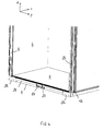
- FIG. 6 which shows the door 6 in its open position, then shows two advantages combined box according to the invention.
- the door 6 is itself deported towards the front of the body; this is the second benefit of the invention since the fact that the door 6 is deported forward a distance substantially equal to the dimension of the flange 13 of the opening profile 12, makes the door 6 is less likely to hit a dock, particularly when the vehicle is angled against the dock; in any event, if the vehicle, at the level of the articulation of the doors 6 on the body 1 were to strike the platform, the shock zone would be circumscribed to the frame profile 8 and / or to the hinge 25 and / or to the profile opening 12 which constitute standard elements that can be replaced in a simple manner.
- the invention provides an insulated body whose rear part, and in particular the means of articulation of the doors 6 on the body, takes into account the problem of docking against a platform by proposing additional protections arranged at level of the edge of the side walls 4 which are traditionally very exposed to shocks; in addition, the provisions of the invention allow an offset of the doors 6 out of the collision zone with the dock.
- the invention also has a second aspect which is related to the fact that the mode of connection of the doors 6 by hinges 29 double node can affect the overall rigidity of the body 1 and, in particular, its rigidity in response to torsional stresses.
- stiffening inserts 35 including metal in each of the doors 6, at the corners thereof which are at the intersection of the floor 3 and the side walls 4 .
- the stiffening inserts 35 are provided with the two lateral angles of each of the doors 6.
- the function of the stiffening inserts 35 is to provide a reinforcement of the box in its critical areas, namely in its areas of connection between its walls. In this configuration of the invention in which four stiffening inserts 35 are respectively fit into the four corners of the rear opening, the rigidity of the body is significantly improved.
- the stiffening insert 35 may comprise two L-shaped metal plates 36 which register at the lateral angles of each of the doors; these two metal plates 36 which, in the example shown are perforated, are each bonded to the inner faces of the two walls forming the rear door panels 6. Spacers 37 hold at a constant distance the plates 36. It can be seen in FIG. . 6 that the stiffening insert 35 bears against an intermediate shim 38 conventionally present in the doors 6.
- stiffening inserts 35 allows, without degrading the isothermal performance of the doors 6, to ensure recovery of the torsional forces that apply to the body. These efforts are particularly important during the transport of suspended loads on the side walls 4; typically, it is the transport of animal carcasses for which the use of an insulated box is essential.
- the invention thus provides an insulated body which takes into account the problem of the docking against a dock by proposing to protect the edges of the side walls 4 which are particularly exposed during the berthing and proposing to deport forward the doors 6 in their open configuration to extract them from the collision zone with the dock.
- the invention proposes to stiffen the body by adding stiffening inserts 35 at the corners of the doors 6 which fit at each corner of the opening so that the doors 6, when they are closed, ensure a real recovery efforts, including torsional efforts that solicit the fund.
- the body according to the invention has a rear portion which is free of asperities found on the crates of the prior art; these asperities are due in particular to the presence of hinges for hinging the doors 6.
- the smooth appearance of the rear part is in particular obtained thanks to the opening profile 12 which masks the damping stops and in which the double knuckle hinges are melted.
- stiffening insert or inserts 35 can be integrated in the thickness of the door or can be attached to the outside of the door on its outer face or on its inner face.
Landscapes
- Engineering & Computer Science (AREA)
- Transportation (AREA)
- Thermal Sciences (AREA)
- Physics & Mathematics (AREA)
- Mechanical Engineering (AREA)
- Public Health (AREA)
- Combustion & Propulsion (AREA)
- Health & Medical Sciences (AREA)
- Chemical & Material Sciences (AREA)
- Body Structure For Vehicles (AREA)
- Refrigerator Housings (AREA)
- Passenger Equipment (AREA)
- Vehicle Step Arrangements And Article Storage (AREA)
- Thermally Insulated Containers For Foods (AREA)
- Processing And Handling Of Plastics And Other Materials For Molding In General (AREA)
- Transition And Organic Metals Composition Catalysts For Addition Polymerization (AREA)
Applications Claiming Priority (1)
| Application Number | Priority Date | Filing Date | Title |
|---|---|---|---|
| FR0606610A FR2903944B1 (fr) | 2006-07-20 | 2006-07-20 | Caisse isotherme pour un vehicule |
Publications (2)
| Publication Number | Publication Date |
|---|---|
| EP1880930A1 true EP1880930A1 (de) | 2008-01-23 |
| EP1880930B1 EP1880930B1 (de) | 2009-12-30 |
Family
ID=37685274
Family Applications (1)
| Application Number | Title | Priority Date | Filing Date |
|---|---|---|---|
| EP07356040A Not-in-force EP1880930B1 (de) | 2006-07-20 | 2007-03-29 | Isothermbehälter für ein Fahrzeug |
Country Status (4)
| Country | Link |
|---|---|
| EP (1) | EP1880930B1 (de) |
| AT (1) | ATE453561T1 (de) |
| DE (1) | DE602007004032D1 (de) |
| FR (1) | FR2903944B1 (de) |
Citations (1)
| Publication number | Priority date | Publication date | Assignee | Title |
|---|---|---|---|---|
| EP1288112A1 (de) * | 2001-08-30 | 2003-03-05 | Univan S.p.A. | Bausatz aus ineinander einsteckbaren Elementen für einen schnellen Zusammenbau van Kraftfahrzeugkästen |
-
2006
- 2006-07-20 FR FR0606610A patent/FR2903944B1/fr not_active Expired - Fee Related
-
2007
- 2007-03-29 EP EP07356040A patent/EP1880930B1/de not_active Not-in-force
- 2007-03-29 DE DE602007004032T patent/DE602007004032D1/de not_active Expired - Fee Related
- 2007-03-29 AT AT07356040T patent/ATE453561T1/de not_active IP Right Cessation
Patent Citations (1)
| Publication number | Priority date | Publication date | Assignee | Title |
|---|---|---|---|---|
| EP1288112A1 (de) * | 2001-08-30 | 2003-03-05 | Univan S.p.A. | Bausatz aus ineinander einsteckbaren Elementen für einen schnellen Zusammenbau van Kraftfahrzeugkästen |
Also Published As
| Publication number | Publication date |
|---|---|
| FR2903944B1 (fr) | 2008-08-29 |
| DE602007004032D1 (de) | 2010-02-11 |
| ATE453561T1 (de) | 2010-01-15 |
| EP1880930B1 (de) | 2009-12-30 |
| FR2903944A1 (fr) | 2008-01-25 |
Similar Documents
| Publication | Publication Date | Title |
|---|---|---|
| EP0159206B1 (de) | Seitentüren von Fahrzeugkarosserien und Containern | |
| EP1609669B1 (de) | Hilfsrahmenstruktur für Förderfahrzeuge mit mindestens drei Achsen, lenkbar, und mit Kippgestell. | |
| EP3678879A1 (de) | Mechanismus für einen kraftfahrzeugkofferraum mit zwei öffnungspaneelen | |
| FR2928633A1 (fr) | Benne pour le transport et/ou le stockage de charge(s) | |
| EP3592631B1 (de) | Anordnung zum halten eines gepäckraumbehälters an der vorderseite einer kraftfahrzeugkarosseriestruktur | |
| EP1880930B1 (de) | Isothermbehälter für ein Fahrzeug | |
| EP2692561B1 (de) | Vorrichtung zum Verschliessen des Laderaumes eines Transportfahrzeuges | |
| FR2939343A1 (fr) | Procede de fabrication d'une porte de vehicule automobile | |
| FR3097474A1 (fr) | Renfort horizontal de porte de véhicule automobile | |
| FR2819227A1 (fr) | Poussoir d'ejection, benne a dechargement horizontal equipee d'un tel poussoir, et vehicule equipe d'une telle benne | |
| FR2922872A1 (fr) | Benne pour le stockage et/ou le transport de charges | |
| FR2917049A1 (fr) | Structure de vehicule automobile pour choc frontal. | |
| FR3087182A1 (fr) | Carrosserie de vehicule routier de transport de marchandises munie d'un deflecteur superieur arriere | |
| EP3626496B1 (de) | Verstärkte sicherheitsseitentür für fahrzeug | |
| EP3737575B1 (de) | Mittelschienengehäuse einer schiebetür eines kraftfahrzeuges | |
| FR2615471A1 (fr) | Caisse de vehicules de transport routier | |
| EP0329552B1 (de) | Behälter zum Transport von Gütern, wie Güterbahnwagen | |
| FR3071216B1 (fr) | Compartiment de transport de marchandise a porte sectionnelle et vehicule comprenant un tel compartiment | |
| FR2721291A1 (fr) | Attache pour latte transversale de plancher de benne à ordures. | |
| EP3044020A1 (de) | Heckklappe eines kraftfahrzeugs mit einem stützrahmen und entsprechendes fahrzeug | |
| FR3005606A1 (fr) | Hayon destine a etre monte articule sur une caisse de vehicule automobile, a butee perfectionnee | |
| FR2554795A1 (fr) | Construction de plate-forme de chargement | |
| FR2781188A1 (fr) | Coffre pour l'equipement de vehicules tels que camions, remorques ou semi-remorques, notamment pour le rangement et le transport de palettes de manutention | |
| FR3011802A1 (fr) | Dispositif de fixation d'une traverse de poste de conduite d'un vehicule automobile | |
| FR2871419A1 (fr) | Benne de transport et/ou de stockage des materiaux |
Legal Events
| Date | Code | Title | Description |
|---|---|---|---|
| PUAI | Public reference made under article 153(3) epc to a published international application that has entered the european phase |
Free format text: ORIGINAL CODE: 0009012 |
|
| AK | Designated contracting states |
Kind code of ref document: A1 Designated state(s): AT BE BG CH CY CZ DE DK EE ES FI FR GB GR HU IE IS IT LI LT LU LV MC MT NL PL PT RO SE SI SK TR |
|
| AX | Request for extension of the european patent |
Extension state: AL BA HR MK YU |
|
| 17P | Request for examination filed |
Effective date: 20080124 |
|
| AKX | Designation fees paid |
Designated state(s): AT BE BG CH CY CZ DE DK EE ES FI FR GB GR HU IE IS IT LI LT LU LV MC MT NL PL PT RO SE SI SK TR |
|
| GRAJ | Information related to disapproval of communication of intention to grant by the applicant or resumption of examination proceedings by the epo deleted |
Free format text: ORIGINAL CODE: EPIDOSDIGR1 |
|
| GRAP | Despatch of communication of intention to grant a patent |
Free format text: ORIGINAL CODE: EPIDOSNIGR1 |
|
| GRAP | Despatch of communication of intention to grant a patent |
Free format text: ORIGINAL CODE: EPIDOSNIGR1 |
|
| GRAS | Grant fee paid |
Free format text: ORIGINAL CODE: EPIDOSNIGR3 |
|
| GRAA | (expected) grant |
Free format text: ORIGINAL CODE: 0009210 |
|
| AK | Designated contracting states |
Kind code of ref document: B1 Designated state(s): AT BE BG CH CY CZ DE DK EE ES FI FR GB GR HU IE IS IT LI LT LU LV MC MT NL PL PT RO SE SI SK TR |
|
| REG | Reference to a national code |
Ref country code: GB Ref legal event code: FG4D Free format text: NOT ENGLISH |
|
| REG | Reference to a national code |
Ref country code: CH Ref legal event code: EP |
|
| REG | Reference to a national code |
Ref country code: IE Ref legal event code: FG4D |
|
| REF | Corresponds to: |
Ref document number: 602007004032 Country of ref document: DE Date of ref document: 20100211 Kind code of ref document: P |
|
| RAP2 | Party data changed (patent owner data changed or rights of a patent transferred) |
Owner name: LAMBERET |
|
| NLT2 | Nl: modifications (of names), taken from the european patent patent bulletin |
Owner name: LAMBERET Effective date: 20100217 |
|
| PG25 | Lapsed in a contracting state [announced via postgrant information from national office to epo] |
Ref country code: FI Free format text: LAPSE BECAUSE OF FAILURE TO SUBMIT A TRANSLATION OF THE DESCRIPTION OR TO PAY THE FEE WITHIN THE PRESCRIBED TIME-LIMIT Effective date: 20091230 Ref country code: LT Free format text: LAPSE BECAUSE OF FAILURE TO SUBMIT A TRANSLATION OF THE DESCRIPTION OR TO PAY THE FEE WITHIN THE PRESCRIBED TIME-LIMIT Effective date: 20091230 Ref country code: SE Free format text: LAPSE BECAUSE OF FAILURE TO SUBMIT A TRANSLATION OF THE DESCRIPTION OR TO PAY THE FEE WITHIN THE PRESCRIBED TIME-LIMIT Effective date: 20091230 |
|
| REG | Reference to a national code |
Ref country code: NL Ref legal event code: VDEP Effective date: 20091230 |
|
| LTIE | Lt: invalidation of european patent or patent extension |
Effective date: 20091230 |
|
| PG25 | Lapsed in a contracting state [announced via postgrant information from national office to epo] |
Ref country code: LV Free format text: LAPSE BECAUSE OF FAILURE TO SUBMIT A TRANSLATION OF THE DESCRIPTION OR TO PAY THE FEE WITHIN THE PRESCRIBED TIME-LIMIT Effective date: 20091230 Ref country code: SI Free format text: LAPSE BECAUSE OF FAILURE TO SUBMIT A TRANSLATION OF THE DESCRIPTION OR TO PAY THE FEE WITHIN THE PRESCRIBED TIME-LIMIT Effective date: 20091230 Ref country code: PL Free format text: LAPSE BECAUSE OF FAILURE TO SUBMIT A TRANSLATION OF THE DESCRIPTION OR TO PAY THE FEE WITHIN THE PRESCRIBED TIME-LIMIT Effective date: 20091230 |
|
| PG25 | Lapsed in a contracting state [announced via postgrant information from national office to epo] |
Ref country code: AT Free format text: LAPSE BECAUSE OF FAILURE TO SUBMIT A TRANSLATION OF THE DESCRIPTION OR TO PAY THE FEE WITHIN THE PRESCRIBED TIME-LIMIT Effective date: 20091230 |
|
| REG | Reference to a national code |
Ref country code: IE Ref legal event code: FD4D |
|
| PG25 | Lapsed in a contracting state [announced via postgrant information from national office to epo] |
Ref country code: PT Free format text: LAPSE BECAUSE OF FAILURE TO SUBMIT A TRANSLATION OF THE DESCRIPTION OR TO PAY THE FEE WITHIN THE PRESCRIBED TIME-LIMIT Effective date: 20100430 Ref country code: IS Free format text: LAPSE BECAUSE OF FAILURE TO SUBMIT A TRANSLATION OF THE DESCRIPTION OR TO PAY THE FEE WITHIN THE PRESCRIBED TIME-LIMIT Effective date: 20100430 Ref country code: ES Free format text: LAPSE BECAUSE OF FAILURE TO SUBMIT A TRANSLATION OF THE DESCRIPTION OR TO PAY THE FEE WITHIN THE PRESCRIBED TIME-LIMIT Effective date: 20100410 Ref country code: NL Free format text: LAPSE BECAUSE OF FAILURE TO SUBMIT A TRANSLATION OF THE DESCRIPTION OR TO PAY THE FEE WITHIN THE PRESCRIBED TIME-LIMIT Effective date: 20091230 Ref country code: BG Free format text: LAPSE BECAUSE OF FAILURE TO SUBMIT A TRANSLATION OF THE DESCRIPTION OR TO PAY THE FEE WITHIN THE PRESCRIBED TIME-LIMIT Effective date: 20100330 Ref country code: RO Free format text: LAPSE BECAUSE OF FAILURE TO SUBMIT A TRANSLATION OF THE DESCRIPTION OR TO PAY THE FEE WITHIN THE PRESCRIBED TIME-LIMIT Effective date: 20091230 Ref country code: EE Free format text: LAPSE BECAUSE OF FAILURE TO SUBMIT A TRANSLATION OF THE DESCRIPTION OR TO PAY THE FEE WITHIN THE PRESCRIBED TIME-LIMIT Effective date: 20091230 |
|
| PG25 | Lapsed in a contracting state [announced via postgrant information from national office to epo] |
Ref country code: CZ Free format text: LAPSE BECAUSE OF FAILURE TO SUBMIT A TRANSLATION OF THE DESCRIPTION OR TO PAY THE FEE WITHIN THE PRESCRIBED TIME-LIMIT Effective date: 20091230 Ref country code: SK Free format text: LAPSE BECAUSE OF FAILURE TO SUBMIT A TRANSLATION OF THE DESCRIPTION OR TO PAY THE FEE WITHIN THE PRESCRIBED TIME-LIMIT Effective date: 20091230 |
|
| BERE | Be: lapsed |
Owner name: LAMBERET CONSTRUCTIONS ISOTHERMES Effective date: 20100331 |
|
| PG25 | Lapsed in a contracting state [announced via postgrant information from national office to epo] |
Ref country code: CY Free format text: LAPSE BECAUSE OF FAILURE TO SUBMIT A TRANSLATION OF THE DESCRIPTION OR TO PAY THE FEE WITHIN THE PRESCRIBED TIME-LIMIT Effective date: 20091230 Ref country code: GR Free format text: LAPSE BECAUSE OF FAILURE TO SUBMIT A TRANSLATION OF THE DESCRIPTION OR TO PAY THE FEE WITHIN THE PRESCRIBED TIME-LIMIT Effective date: 20100331 Ref country code: IE Free format text: LAPSE BECAUSE OF FAILURE TO SUBMIT A TRANSLATION OF THE DESCRIPTION OR TO PAY THE FEE WITHIN THE PRESCRIBED TIME-LIMIT Effective date: 20091230 Ref country code: MC Free format text: LAPSE BECAUSE OF NON-PAYMENT OF DUE FEES Effective date: 20100331 |
|
| PLBE | No opposition filed within time limit |
Free format text: ORIGINAL CODE: 0009261 |
|
| STAA | Information on the status of an ep patent application or granted ep patent |
Free format text: STATUS: NO OPPOSITION FILED WITHIN TIME LIMIT |
|
| 26N | No opposition filed |
Effective date: 20101001 |
|
| REG | Reference to a national code |
Ref country code: FR Ref legal event code: ST Effective date: 20101130 |
|
| PG25 | Lapsed in a contracting state [announced via postgrant information from national office to epo] |
Ref country code: FR Free format text: LAPSE BECAUSE OF NON-PAYMENT OF DUE FEES Effective date: 20100331 Ref country code: DK Free format text: LAPSE BECAUSE OF FAILURE TO SUBMIT A TRANSLATION OF THE DESCRIPTION OR TO PAY THE FEE WITHIN THE PRESCRIBED TIME-LIMIT Effective date: 20091230 |
|
| PG25 | Lapsed in a contracting state [announced via postgrant information from national office to epo] |
Ref country code: BE Free format text: LAPSE BECAUSE OF NON-PAYMENT OF DUE FEES Effective date: 20100331 Ref country code: DE Free format text: LAPSE BECAUSE OF NON-PAYMENT OF DUE FEES Effective date: 20101001 |
|
| PG25 | Lapsed in a contracting state [announced via postgrant information from national office to epo] |
Ref country code: IT Free format text: LAPSE BECAUSE OF FAILURE TO SUBMIT A TRANSLATION OF THE DESCRIPTION OR TO PAY THE FEE WITHIN THE PRESCRIBED TIME-LIMIT Effective date: 20091230 |
|
| PG25 | Lapsed in a contracting state [announced via postgrant information from national office to epo] |
Ref country code: MT Free format text: LAPSE BECAUSE OF FAILURE TO SUBMIT A TRANSLATION OF THE DESCRIPTION OR TO PAY THE FEE WITHIN THE PRESCRIBED TIME-LIMIT Effective date: 20091230 |
|
| REG | Reference to a national code |
Ref country code: CH Ref legal event code: PL |
|
| GBPC | Gb: european patent ceased through non-payment of renewal fee |
Effective date: 20110329 |
|
| PG25 | Lapsed in a contracting state [announced via postgrant information from national office to epo] |
Ref country code: CH Free format text: LAPSE BECAUSE OF NON-PAYMENT OF DUE FEES Effective date: 20110331 Ref country code: LI Free format text: LAPSE BECAUSE OF NON-PAYMENT OF DUE FEES Effective date: 20110331 |
|
| PG25 | Lapsed in a contracting state [announced via postgrant information from national office to epo] |
Ref country code: GB Free format text: LAPSE BECAUSE OF NON-PAYMENT OF DUE FEES Effective date: 20110329 |
|
| PG25 | Lapsed in a contracting state [announced via postgrant information from national office to epo] |
Ref country code: LU Free format text: LAPSE BECAUSE OF NON-PAYMENT OF DUE FEES Effective date: 20100329 Ref country code: HU Free format text: LAPSE BECAUSE OF FAILURE TO SUBMIT A TRANSLATION OF THE DESCRIPTION OR TO PAY THE FEE WITHIN THE PRESCRIBED TIME-LIMIT Effective date: 20100701 |
|
| PG25 | Lapsed in a contracting state [announced via postgrant information from national office to epo] |
Ref country code: TR Free format text: LAPSE BECAUSE OF FAILURE TO SUBMIT A TRANSLATION OF THE DESCRIPTION OR TO PAY THE FEE WITHIN THE PRESCRIBED TIME-LIMIT Effective date: 20091230 |