EP1880467B1 - Positioning apparatus and method - Google Patents
Positioning apparatus and method Download PDFInfo
- Publication number
- EP1880467B1 EP1880467B1 EP06726944A EP06726944A EP1880467B1 EP 1880467 B1 EP1880467 B1 EP 1880467B1 EP 06726944 A EP06726944 A EP 06726944A EP 06726944 A EP06726944 A EP 06726944A EP 1880467 B1 EP1880467 B1 EP 1880467B1
- Authority
- EP
- European Patent Office
- Prior art keywords
- travelling
- end surface
- electrodes
- tube
- tubular body
- Prior art date
- Legal status (The legal status is an assumption and is not a legal conclusion. Google has not performed a legal analysis and makes no representation as to the accuracy of the status listed.)
- Not-in-force
Links
- 238000000034 method Methods 0.000 title claims description 38
- 230000033001 locomotion Effects 0.000 claims abstract description 99
- 230000000694 effects Effects 0.000 claims abstract description 25
- 230000003993 interaction Effects 0.000 claims abstract description 10
- 239000000463 material Substances 0.000 claims description 61
- 238000013519 translation Methods 0.000 claims description 26
- 238000006073 displacement reaction Methods 0.000 claims description 15
- 230000005684 electric field Effects 0.000 claims description 6
- 239000000523 sample Substances 0.000 description 35
- 230000014616 translation Effects 0.000 description 23
- 238000005452 bending Methods 0.000 description 19
- 230000005284 excitation Effects 0.000 description 19
- 239000002245 particle Substances 0.000 description 13
- 230000008901 benefit Effects 0.000 description 7
- 239000007787 solid Substances 0.000 description 7
- 239000011248 coating agent Substances 0.000 description 6
- 238000000576 coating method Methods 0.000 description 6
- 230000000284 resting effect Effects 0.000 description 6
- 230000005484 gravity Effects 0.000 description 4
- 230000008859 change Effects 0.000 description 3
- 239000002131 composite material Substances 0.000 description 3
- 230000010355 oscillation Effects 0.000 description 3
- 239000000356 contaminant Substances 0.000 description 2
- 239000000203 mixture Substances 0.000 description 2
- CWYNVVGOOAEACU-UHFFFAOYSA-N Fe2+ Chemical compound [Fe+2] CWYNVVGOOAEACU-UHFFFAOYSA-N 0.000 description 1
- 238000004630 atomic force microscopy Methods 0.000 description 1
- 238000010276 construction Methods 0.000 description 1
- 125000004122 cyclic group Chemical group 0.000 description 1
- 230000001747 exhibiting effect Effects 0.000 description 1
- 238000004519 manufacturing process Methods 0.000 description 1
- 238000000386 microscopy Methods 0.000 description 1
- 230000004048 modification Effects 0.000 description 1
- 238000012986 modification Methods 0.000 description 1
- 238000005057 refrigeration Methods 0.000 description 1
- 230000004044 response Effects 0.000 description 1
- 238000004574 scanning tunneling microscopy Methods 0.000 description 1
- 230000011218 segmentation Effects 0.000 description 1
Images


Classifications
-
- G—PHYSICS
- G01—MEASURING; TESTING
- G01Q—SCANNING-PROBE TECHNIQUES OR APPARATUS; APPLICATIONS OF SCANNING-PROBE TECHNIQUES, e.g. SCANNING PROBE MICROSCOPY [SPM]
- G01Q10/00—Scanning or positioning arrangements, i.e. arrangements for actively controlling the movement or position of the probe
- G01Q10/02—Coarse scanning or positioning
-
- B—PERFORMING OPERATIONS; TRANSPORTING
- B82—NANOTECHNOLOGY
- B82Y—SPECIFIC USES OR APPLICATIONS OF NANOSTRUCTURES; MEASUREMENT OR ANALYSIS OF NANOSTRUCTURES; MANUFACTURE OR TREATMENT OF NANOSTRUCTURES
- B82Y35/00—Methods or apparatus for measurement or analysis of nanostructures
-
- G—PHYSICS
- G01—MEASURING; TESTING
- G01Q—SCANNING-PROBE TECHNIQUES OR APPARATUS; APPLICATIONS OF SCANNING-PROBE TECHNIQUES, e.g. SCANNING PROBE MICROSCOPY [SPM]
- G01Q10/00—Scanning or positioning arrangements, i.e. arrangements for actively controlling the movement or position of the probe
- G01Q10/04—Fine scanning or positioning
-
- H—ELECTRICITY
- H02—GENERATION; CONVERSION OR DISTRIBUTION OF ELECTRIC POWER
- H02N—ELECTRIC MACHINES NOT OTHERWISE PROVIDED FOR
- H02N2/00—Electric machines in general using piezoelectric effect, electrostriction or magnetostriction
- H02N2/0095—Electric machines in general using piezoelectric effect, electrostriction or magnetostriction producing combined linear and rotary motion, e.g. multi-direction positioners
-
- H—ELECTRICITY
- H02—GENERATION; CONVERSION OR DISTRIBUTION OF ELECTRIC POWER
- H02N—ELECTRIC MACHINES NOT OTHERWISE PROVIDED FOR
- H02N2/00—Electric machines in general using piezoelectric effect, electrostriction or magnetostriction
- H02N2/02—Electric machines in general using piezoelectric effect, electrostriction or magnetostriction producing linear motion, e.g. actuators; Linear positioners ; Linear motors
- H02N2/028—Electric machines in general using piezoelectric effect, electrostriction or magnetostriction producing linear motion, e.g. actuators; Linear positioners ; Linear motors along multiple or arbitrary translation directions, e.g. XYZ stages
-
- H—ELECTRICITY
- H02—GENERATION; CONVERSION OR DISTRIBUTION OF ELECTRIC POWER
- H02N—ELECTRIC MACHINES NOT OTHERWISE PROVIDED FOR
- H02N2/00—Electric machines in general using piezoelectric effect, electrostriction or magnetostriction
- H02N2/02—Electric machines in general using piezoelectric effect, electrostriction or magnetostriction producing linear motion, e.g. actuators; Linear positioners ; Linear motors
- H02N2/08—Electric machines in general using piezoelectric effect, electrostriction or magnetostriction producing linear motion, e.g. actuators; Linear positioners ; Linear motors using travelling waves, i.e. Rayleigh surface waves
-
- H—ELECTRICITY
- H02—GENERATION; CONVERSION OR DISTRIBUTION OF ELECTRIC POWER
- H02N—ELECTRIC MACHINES NOT OTHERWISE PROVIDED FOR
- H02N2/00—Electric machines in general using piezoelectric effect, electrostriction or magnetostriction
- H02N2/10—Electric machines in general using piezoelectric effect, electrostriction or magnetostriction producing rotary motion, e.g. rotary motors
- H02N2/108—Electric machines in general using piezoelectric effect, electrostriction or magnetostriction producing rotary motion, e.g. rotary motors around multiple axes of rotation, e.g. spherical rotor motors
-
- H—ELECTRICITY
- H02—GENERATION; CONVERSION OR DISTRIBUTION OF ELECTRIC POWER
- H02N—ELECTRIC MACHINES NOT OTHERWISE PROVIDED FOR
- H02N2/00—Electric machines in general using piezoelectric effect, electrostriction or magnetostriction
- H02N2/10—Electric machines in general using piezoelectric effect, electrostriction or magnetostriction producing rotary motion, e.g. rotary motors
- H02N2/16—Electric machines in general using piezoelectric effect, electrostriction or magnetostriction producing rotary motion, e.g. rotary motors using travelling waves, i.e. Rayleigh surface waves
- H02N2/163—Motors with ring stator
-
- B—PERFORMING OPERATIONS; TRANSPORTING
- B82—NANOTECHNOLOGY
- B82Y—SPECIFIC USES OR APPLICATIONS OF NANOSTRUCTURES; MEASUREMENT OR ANALYSIS OF NANOSTRUCTURES; MANUFACTURE OR TREATMENT OF NANOSTRUCTURES
- B82Y10/00—Nanotechnology for information processing, storage or transmission, e.g. quantum computing or single electron logic
-
- G—PHYSICS
- G11—INFORMATION STORAGE
- G11B—INFORMATION STORAGE BASED ON RELATIVE MOVEMENT BETWEEN RECORD CARRIER AND TRANSDUCER
- G11B9/00—Recording or reproducing using a method not covered by one of the main groups G11B3/00 - G11B7/00; Record carriers therefor
- G11B9/12—Recording or reproducing using a method not covered by one of the main groups G11B3/00 - G11B7/00; Record carriers therefor using near-field interactions; Record carriers therefor
- G11B9/14—Recording or reproducing using a method not covered by one of the main groups G11B3/00 - G11B7/00; Record carriers therefor using near-field interactions; Record carriers therefor using microscopic probe means, i.e. recording or reproducing by means directly associated with the tip of a microscopic electrical probe as used in Scanning Tunneling Microscopy [STM] or Atomic Force Microscopy [AFM] for inducing physical or electrical perturbations in a recording medium; Record carriers or media specially adapted for such transducing of information
- G11B9/1418—Disposition or mounting of heads or record carriers
- G11B9/1427—Disposition or mounting of heads or record carriers with provision for moving the heads or record carriers relatively to each other or for access to indexed parts without effectively imparting a relative movement
- G11B9/1436—Disposition or mounting of heads or record carriers with provision for moving the heads or record carriers relatively to each other or for access to indexed parts without effectively imparting a relative movement with provision for moving the heads or record carriers relatively to each other
Definitions
- the present invention relates to apparatus and methods for positioning objects, and in particular, although not exclusively, to apparatus and methods for accurate positioning of objects on a nanometre scale or even finer.
- the positioning apparatus and methods may also be described as manipulation apparatus and methods.
- a positioning system that can provide both a relatively wide range of overall movement (e.g. on the centimetre scale) and yet fine positional control within that range (e.g. a resolution on the micro or nanometre scale, or better).
- This apparatus comprises a stack of three piezoelectric translators, each of which can be regarded as a type of linear motor and has a base member and a movable member having one degree of freedom.
- Each translator is controllable to provide "coarse" movement (in this example coarse movement is to be considered as movement in the range 1 micron to 1 centimetre) of its movable member in one of the three orthogonal directions (the nominal X, Y and Z directions in the figure).
- This movement i.e. translation in one dimension
- the base comprises a piezoelectric member and a surface of the movable member is clamped against a surface of the piezoelectric member by suitable clamping means.
- the clamping means may be adjustable so as to adjust the friction force.
- the piezoelectric member is then controlled, with a suitable control voltage, such that its surface in contact with the movable member performs sawtooth-like oscillations along the direction of intended translation, i.e. it undergoes a series of slow movements in the direction of intended translation, with rapid movements in the opposite direction in between. If the clamping force is suitably arranged then during the slow movements the two surfaces "stick" and the movable member is moved, but during the fast movements there is slippage and the movable member is not moved. Thus, the asymmetric oscillations, which cause the slipping in one direction and sticking in the opposite direction, result in translation of the movable member. Large translations can thus be built up incrementally from the relatively small translations in each "stick" part of the slip-stick cycle.
- the first translator, or stage, XC provides coarse movement control of its movable member in the X direction.
- the second translator YC has its base mounted on the first stage's movable member, and provides independent coarse movement control of its own movable member in the Y direction.
- the third stage ZC is mounted on the second stage to provide coarse Z movement control.
- the interface between the base and movable portions of the third translator is thus vertical, and a disadvantage with the illustrated apparatus is that, as a result of this vertical interface, the weight of any further structure carried by the third stage is limited.
- the last translator ZC carries a device for fine movement on the 1 nanometre - 1 micron scale.
- This fine movement device is a piezoelectric tube capable of 3 degrees of freedom movement (XYZfine). It is known for the tube to be provided with an electrode arrangement such as that shown in figure 8 (and which is also suitable for use in embodiments of the invention for the same purpose, i.e. to enable fine positional control in three directions). In such an arrangement the tube has electrodes on an outer and on an inner side, and the outer electrodes are segmented to form four independently drivable sectors on the tube.
- Fine movement control in the Z direction can be achieved by controlling a voltage applied to the outer electrodes in common, relative to the inner electrode, to produce longitudinal extension or shrinkage of the tube.
- Fine movement of the tube upper end surface in the X direction can be achieved by applying a potential difference between one opposing pair of outer electrodes (to bend the tube, as the material under one electrode is elongated and that under the opposite electrode shrinks with respect to the longitudinal axis).
- a differential voltage may be applied between the other pair of outer electrodes.
- figure 1 Although the arrangement of figure 1 , comprising three coarse translators and a piezoelectric tube, does provide both fine and coarse movement control in the X, Y and Z axes, there are a number of disadvantages associated with it.
- the large number of components leads to the unit being expensive, and increases the probability of some failure occurring.
- the assembly has a relatively large size and mass, which can cause refrigeration problems in certain applications where positioning or manipulation at low temperatures is required; the large size means that a correspondingly large volume must be cooled, and then held at low temperature, the large mass means that a relatively large quantity of heat must be removed to lower the positioning apparatus to the required temperature.
- the large mass also means that changes from one stable temperature to another desired stable temperature can only be achieved slowly.
- the arrangement of the tube on a stack of three translators is also highly susceptible to external vibrations.
- the relatively large size furthermore results in the arrangement exhibiting mechanical (acoustical) noise susceptibility.
- Thermal drifts are also a problem, as are the limited accessibility of manipulator and the limitations on applications for the manipulator resulting from its relatively large overall size.
- EP 938 144 A2 describes an ultrasonic motor comprising a piezoelectric tube with electrodes exciting composite bending and elongating vibrations to linearly and/or rotationally move a plate.
- WO 98/07200 A1 teaches the rotation of a sphere about multiple axes by a piezoelectric hom with sectioned electrodes in which it is possible to generate travelling wave type oscillations in the contact area.
- positioning apparatus comprising:
- the relative movement effected by interaction between the two travelling waves and the first surface may comprise a translation in a direction transverse to the longitudinal axis or a rotation about an axis other than the longitudinal axis (for example rotation about an axis perpendicular to the longitudinal axis).
- a translation in a direction transverse to the longitudinal axis or a rotation about an axis other than the longitudinal axis for example rotation about an axis perpendicular to the longitudinal axis.
- the tubular body is a tube of piezoelectric material, and the surface waves are generated by application of control voltages to appropriately arranged electrodes.
- the tube may comprise magnetostrictive material, in which case the wave generation system will include means for application of suitable magnetic fields.
- Piezoelectric and magnetostrictive materials are merely examples, however, and in general the tube may have any composition or structure provided that the wave generation system is able to generate the required surface waves.
- the surface wave generation means may also be described as end surface deformation means, a surface wave generator, or a surface wave generation system.
- the first and second portions may also be described as first and second segments, and the tubular body may also be referred to as a tubular member.
- First and second travelling surface waves may also be described as travelling deformation waves.
- the deformation of the end surface as the wave travels along comprises at least deformation in direction parallel to the longitudinal axis, i.e. deformation or displacement transverse to the wave propagation direction (which deformation could be used on its own to move an appropriately shaped first surface), but in certain preferred embodiments the deformation additionally comprises longitudinal deformation with respect to propagation direction.
- the first end surface is generally annular, and may be planar or be a section of a conical, cylindrical, or spherical surface, for example. Generally, the first end surface faces away from the tubular body, along the longitudinal axis.
- tubular body is a hollow cylinder having a circular cross section, but tubes having alternative cross-sectional shapes may be used.
- the tubular body is a solid body, and as mentioned above it may comprise piezoelectric material, which may be polycrystalline. Electric fields may then be applied to the material to effect dimensional changes and generate the first and second travelling surface waves.
- the tube is composed entirely of piezoelectric material, but in alternative embodiments a composite material or a combination of materials may form the tube.
- the surface wave generation means may comprises a plurality of electrodes circumferentially spaced apart around an outer surface and/or an inner surface of the tubular body.
- the wave generation means then additionally comprises control means arranged to apply voltages to the spaced-apart electrodes in a predetermined manner (e.g. a predetermined sequence) so as to effect dimensional changes in the piezoelectric material (in other words, to produce strains of the material) and generate the first and second travelling surface waves at the first end surface.
- the spaced-apart electrodes may include a first group of electrodes extending around a first section (segment) of the tubular body, the first portion of the first end surface being an end surface of the first section, and a second group of electrodes extending around a second section (segment) of the tubular body, the second portion of the first end surface being an end surface of the second section.
- the electrodes for wave generation may be positioned next to the surface portions on which the two waves are generated. These electrodes for wave generation at the first end may be confined to a first end longitudinal segment of the body.
- the spaced-apart electrodes are directly attached to the outer and/or inner surfaces of the tubular body.
- the apparatus may further comprise an array of electrodes arranged around a second longitudinal segment of the tubular body, the second longitudinal segment being on the opposite side of the first longitudinal segment to the first end, and displacement control means arranged to apply voltages to the electrodes of the array so as to effect dimensional changes in the piezoelectric material which result in displacement of the first end surface in at least one direction perpendicular to the longitudinal axis.
- the array of electrodes on the second longitudinal segment can be used to produce controlled bending of the tube.
- the array of electrodes comprises four electrodes in certain preferred embodiments, those four being spaced around the second longitudinal segment and comprising a first diametrically opposed pair and a second diametrically opposed pair.
- the displacement control means is then arranged to apply voltages to the electrodes of the first pair to effect displacement of the first end surface in a first direction perpendicular to the longitudinal axis and to apply voltages to the electrodes of the second pair to effect displacement of the first end surface in a second direction perpendicular to the longitudinal axis.
- voltages applied in unison to all electrodes of the second longitudinal segment may be used to effect displacement (of the end surface) in a direction parallel to the longitudinal axis.
- a separate circular electrode is used to effect displacement in a direction parallel to the longitudinal axis.
- a pair of circular electrodes may be arranged on inner and outer surfaces respectively of a longitudinal section of the tubular body (as described below, with reference to figures 2, 3 and 51 ), and a differential voltage applied between these inner and outer electrode “rings” to control elongation/shrinkage along the longitudinal axis.
- the first surface is flat, and the first and second travelling waves may interact with the first surface to effect relative movement comprising a relative translation between the tubular body and the first surface.
- the first surface may be spherical or cylindrical, and the first and second travelling waves may interact with the first surface to effect relative movement comprising a relative rotation between the tubular body and the first surface about an axis perpendicular to the longitudinal axis.
- the first end surface is shaped so as to correspond to the shape of the portion of the first surface with which it is in contact.
- the first end surface is shaped so as to seat against the first surface; the first end surface is shaped so as to conform to the first surface.
- At least one of the surfaces is provided with a surface pattern for entrapping debris and contaminants.
- the pattern comprises grooves. The pattern does not affect the performance of the device as long as there is a large enough number of contact points between the surfaces.
- the number of grooves in the circumference is a multiple of the number of electrodes around the circumference.
- the apparatus may further comprise biasing means arranged to urge the first end surface and the first surface together.
- biasing means arranged to urge the first end surface and the first surface together.
- the first surface and tube may be held together in a variety of orientations; as an extreme example, the tube may be suspended from the first surface.
- the biasing means may take a variety of forms, and may include one or more springs, vacuum suction means, or magnets for example.
- At least one of the first surface and the first end surface comprises wear-resistant material.
- one or both of the first surface and the first end surface may comprise a coating or layer of wear-resistant material.
- the first and second travelling surface waves are surface waves in which surface points undergo elliptical motion as the waves pass by, such as Rayleigh or Rayleigh-type surface waves.
- the first and second portions together comprise the entire first end surface.
- the first and second portions together comprise only a portion of the entire first end surface.
- the remainder of the end surface may be uncontrolled, or alternatively the apparatus may be further arranged to generate an additional surface wave or waves on another portion or portions of the end surface.
- the first and second portions may be diametrically opposed, and the apparatus may include means for generating a further pair of oppositely travelling surface waves on a further pair of diametrically opposed portions of the first end portion. The first and second surface waves may then be used to generate translation in, say, the X direction, and the further waves used to generate translation in the Y direction.
- the first surface is a surface of a body supported by the tube.
- the apparatus may then further comprise a base supporting the tubular body, the base providing a base surface, and the tubular body having a second end surface at a second end of the tubular body, the second end surface being arranged in contact with the base surface.
- the surface wave generation means is then further arranged to generate a third travelling surface wave on the second end surface, the third travelling surface wave travelling along a first portion of the second end surface in a first direction around the second end surface, and, while the third travelling surface wave is travelling along the first portion of the second end surface, to generate a fourth travelling surface wave on the second end surface, the fourth travelling surface wave travelling along a second portion of the second end surface in a second direction around the second end surface, such that the third and fourth travelling surface waves interact with the base surface to effect movement of the tubular body relative to the base.
- the tubular body is a tube of piezoelectric material and the surface wave generation means comprises a plurality of electrodes arranged around a third longitudinal segment of the tubular body.
- the third longitudinal segment is proximate the second end, and control means is arranged to arranged to apply voltages to the third longitudinal segment electrodes in a predetermined sequence so as to effect dimensional changes in the piezoelectric material and generate the third and fourth travelling surface waves.
- surface waves may be generated to translate or rotate a supported body, and at the opposite end, surface waves may be generated to translate the tube over a supporting surface.
- the positioning further comprises biasing means arranged to urge the second end surface and the base surface together, for example to hold them securely together and/or to permit use of the apparatus in various orientations.
- At least one of the second end surface and the base surface preferably comprises wear-resistant material.
- the second end surface and the base surface are flat, and the movement effected between the tubular body and the base comprises translation of the tubular body over the base surface.
- a method of effecting relative movement between a first surface and a tubular body, the tubular body having a longitudinal axis and an end surface at one end of the tubular body comprising the steps of:
- the first surface and the end surface may be flat, the method producing relative translation between the first surface and the end surface, or the first surface may be curved, the method producing relative rotation between the first surface and the end surface about an axis other than the longitudinal axis.
- the tubular body is a tube of piezoelectric material and the steps of generating the first and second travelling surface waves comprise arranging a first group of electrodes adjacent the first portion of the end surface and arranging a second group of electrodes adjacent the second portion of the end surface and applying voltages to the electrodes of the first and second groups in a predetermined sequence.
- Figs. 2 & 3 illustrates a technique for using a tube of piezoelectric material to produce fine movement in a nominal Z direction.
- This technique may be used in embodiments of the invention.
- the tube is coupled to a surface 51 of a base 5.
- a first circular electrode E1 is attached to the outer surface of the tube, and a second circular electrode EC is attached to the inner surface of the tube.
- the piezoelectric material of the tube is polarized radially and a voltage V is applied between the electrodes deposited outside and inside the tube. This applies an electric field to the piezoelectric material which results in elongation or shrinkage of the tube (according to the sign of the applied potential difference) in a direction parallel to the longitudinal axis of the tube (i.e.
- Figs. 4 & 5 illustrates another technique which may be used in embodiments of the present of the invention to achieve fine movement in a nominal X direction with a piezoelectric tube.
- four electrodes are attached to tube. These four electrodes are a first outer electrode E1 and a first inner electrode EC1 (which are arranged to extend around the outer and inner surfaces respectively of one half of the tube) and a second outer electrode E2 and a second inner electrode EC2 (which are arranged to extend around the opposite half of the tube). Voltages of opposite sign are then applied to the two halves of the tube. This makes one half of the tube extend and the other shrink. This results in a small amount of bending of the tube which results in the end surface 21 moving in the X direction, as indicated by the arrow labelled "X fine" in the figures.
- FIGS. 6 & 7 show an alternative technique of achieving bending of the tube to produce fine displacement of the end surface in the X direction.
- a single inner electrode EC is used, and only the outer surface is segmented into first and second outer electrodes E1 and E2.
- the inner electrode electric potential can be left floating or grounded. Bending of the tube can be achieved by application of a differential voltage between the first and second outer electrodes E1 and E2. It will also be appreciated that the two halves of the tube can be independently driven if only one voltage is varied, the voltage to the other outer electrode being held constant. It will also be appreciated that rather than using a single inner electrode and two outer electrodes to achieve fine X control, a single circular outer electrode could be used in conjunction with a segmented inner electrode.
- Figs. 8 & 9 illustrate a technique for achieving fine movement control in three mutually perpendicular directions (the nominal X, Y and Z directions in the figure, the Z direction being perpendicular to the surface 51 of the base 5 and the X and Y directions being parallel to the base surface 51).
- four electrodes E1, E2, E3 and E4 are arranged around the tube outer surface and a common inner electrode is arranged around the inner surface of the tube. This electrode arrangement affectively divides the tube into four independently controllable tube segments.
- a potential difference between the opposed electrodes E1 and E3 provides the bending of the tube to displace the end surface in the Y direction
- an application of a potential difference between the electrodes E2 and E4 produces bending of the tube which displaces the end surface 21 in the nominal X direction.
- a voltage can be applied to all four outer electrodes simultaneously with respect to the common inner electrode to control elongation or shrinkage of the tube in the longitudinal direction, i.e. to achieve fine movement control of the end surface 21 in the Z direction.
- the tube and electrode arrangement can be used to achieve fine positioning of the probe or sample in the X, Y and Z directions relative to the base 5 by application of appropriate voltages to the electrodes.
- Figs. 10 & 11 illustrate an alternative technique of achieving fine positioning of the end surface 21 in the X, Y and Z directions.
- this arrangement only outer electrodes A, B and 0 are arranged around the outer surface of the tube, with a single inner electrode C on the inner surface.
- the electrode arrangement provides control of only three independent segments.
- application of a common voltage to all three outer electrodes with respect to the inner electrode can be used to provide fine Z movement control.
- Fine movement control of the end surface 21 in the X and Y directions is achieved by the application of suitable potential differences between the outer electrodes A, B and O.
- figs. 12a to 12g these illustrate a technique for producing a travelling surface wave on the surface of a body of piezoelectric material, this technique being suitable for use in embodiments of the invention.
- the piezoelectric body is a flat piezoelectric sheet PS having an upper edge surface 21.
- the figures show one side of the sheet PS on which are provided three electrodes E1, E2 and E3.
- the reverse side of the sheet is not shown in the figures, but is provided with a single electrode extending over the entire reverse surface and which is held at a constant potential.
- the three electrodes on the front face of the sheet can be thought of as dividing the sheet into a number of independently controllable segments.
- the application of a voltage greater than the potential of the reverse electrode to one of the front electrodes causes a dimensional change of the piezoelectric material of the respective segment which makes that segment extend in both the vertical and horizontal directions in the figure.
- an application of a voltage sequentially to the electrodes in a chosen direction produces a wave of the upper surface 21 which travels along the upper surface 21. This wave comprises a deformation of the upper surface 21.
- Figs. 12a to 12g illustrate the sequence of steps in the cycle for generating the travelling surface wave.
- Fig. 12a shows the beginning of the cycle in which none of the three electrodes is excited.
- a particle N on the surface 21 of the sheet is shown at an initial, starting position O.
- Fig. 12b shows the next step in the cycle in which an excitation voltage (i.e. potential) has been applied just to the first electrode E1.
- the voltage applied to the first electrode has effected a dimensional change in the piezoelectric material subjected to the resultant electric field, such that the corresponding segment of the sheet has extended in both the vertical and horizontal directions in the figure.
- the arrows superimposed on the first electrode E1 indicate the directions of the sheet expansion.
- FIG 12c shows the next step in the cycle in which the excitation voltage is applied to both the first and second electrodes E1 and E2 but not to the third electrode.
- Application of the voltage to the second electrode in addition to the first has resulted in the particle N lifting upwards, so that it is now displaced upwards and to the right from the starting position O.
- Figure 12d shows the next step in the cycle, in which the excitation voltage is now applied to all three electrodes.
- the additional excitation of third electrode has resulted in the particle N moving to the left in the figure, so that it is now positioned directly above its starting position O (i.e.
- the excitation of the third electrode has resulted in the particle N moving to the left compared with its position if figure 12c ).
- the first electrode E1 has been returned to its initial voltage (i.e. it is no longer excited) but the second and third electrodes remain excited.
- the return of the first electrode voltage to its initial value has resulted in the particle N falling slightly and moving to the left compared with its position the preceding step.
- the excitation voltage has been removed from the second electrode E2 such that only the third electrode E3 remains excited.
- the particle N on the surface has fallen yet further.
- the third electrode E3 is returned to its initial voltage so that no electrode is now excited and the sheet has returned to its initial state, as at the beginning of the cycle.
- the particle N on the surface has been returned to its initial position O.
- the application of control voltages to the series of electrodes in a predetermined sequence has resulted in a generation of a travelling surface wave on the surface 21 of the sheet.
- This surface wave comprises a deformation of the surface that has components in both the vertical and horizontal directions.
- the particle N on the surface 21 makes a cyclic motion as the travelling wave passes by.
- Figure 13 illustrates the timing sequence of the three control voltages applied to the electrodes in the wave generation cycle illustrated by figures 12a to 12g .
- the excitation voltage is denoted by V2
- the initial (non-excitation voltage) is denoted by V1.
- travelling surface waves on the surfaces of piezoelectric buddies can be generated in embodiments of the invention by suitable application of square-wave control voltages.
- control voltages having a different form may be used.
- sinusoidal control voltages may be used, as illustrated by figure 14 .
- These control voltages may be generated by a three-phase generator, and applied to the three electrodes E1, E2 and E3 of the arrangement shown in figures 12a to 12g to generate suitable travelling surface wave on surface 21. This can be thought of, as can the use of the control voltages shown in figure 13 , as driving "caterpillar motion" on the upper surface 21.
- a different number of phases may be used.
- the minimum number of phases that can be used is two, and examples of this will be described below.
- a number of phases greater than three may be used.
- the number of segments composing a period of the travelling wave can be two, three, or more.
- the travelling wave generated on the surface 21 of the piezoelectric body illustrated by figures 12a to 12g is an example of a surface wave on a solid body that may be used in embodiments of the invention.
- the higher the frequency of the control voltage applied to the electrodes e.g. the voltage in fig. 14 ) the faster the surface wave travels.
- a resonance is achieved.
- the surface wave may be considered similar to a Rayleigh wave.
- devices embodying the invention work best at frequencies somewhat below the resonant frequency. This is because two travelling waves (travelling along separate respective portions of the surface) should not penetrate each other. In resonance the waves travel outside the area defined by their electrodes (similar to the phenomenon of inertia in mechanics).
- a snap-shot of a surface wave travelling along the surface of a solid body B in an embodiment of the invention is shown in highly schematic form in figure 15 .
- a single peak of the wave is shown in the figure, and the direction of propagation of the travelling surface wave is shown by arrow W.
- a characteristic of this surface wave is that particles on the surface of the solid body B undergo elliptic motion as the travelling wave passes by. As such, this surface wave can be regarded as being of the Rayleigh-type.
- a single particle N on the surface is shown in the figure, and its elliptical path is denoted by reference E.
- the particle N in this snap shot is located at the peak at the travelling wave and its instantaneous motion is denoted by arrow M.
- this motion (at the top of the elliptical path) is in the opposite direction to the wave propagation direction W.
- a surface is placed on top of the body B in frictional engagement with the upper surface, then the interaction between the travelling surface wave and the supported surface is to drive the supported surface in the direction opposite to the wave propagation direction W.
- each peak of the travelling wave lifts the supported surface and urges it in the reverse direction compared to the wave propagation direction W.
- Such surface waves may be generated in various forms of solid bodies, and are not limited to piezoelectric materials.
- figures 12a to 12g illustrated the production of a travelling surface wave in a piezoelectric body by application of suitable control voltages to an array of electrodes
- alternate embodiments of the invention may utilise materials other than piezoelectric materials and the surface waves may be generated on their surfaces in a different ways.
- embodiments of the invention may utilise a body (such as a tube) of magnetostrictive material, in which case the generation of travelling surface waves on the surface of the body may be achieved by suitable application of magnetic fields.
- piezoelectric materials and magnetostrictive materials are merely examples, and embodiments of the invention are not limited to using just these.
- a travelling surface wave can be generated along a portion of a surface of a piezoelectric body by arranging electrodes to divide the portion into three segments and then exciting the segments with suitable control voltages.
- the portion can be divided into more than three segments.
- the time lag between the control voltages may be 360° divided by the number of segments in a period.
- the segments may, in certain embodiments, form more than one period.
- the minimum number of segments into which the portion is divided by electrodes is two.
- the time lag between the control voltage applied to the first electrode and the control voltage applied to the second electrode should be different from 180°.
- a time lag of 90° is advantageous because when the first segment is maximally lifted, the second electrode has the highest velocity of extension. This develops the maximum lateral velocity of the first segment edge.
- the wave frequency should be fast enough to prevent sticking of the supported moving object to the piezoelectric sheet edge when the edge lowers down and returns back.
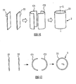
- figs. 12a to 12g show the generation of a travelling surface wave on the surface of a straight sheet of piezoelectric material.
- a piezoelectric tube is used, and relative motion between the tube and a surface with which the tube is in contact is achieved by generating travelling waves which travel in opposite directions around an end surface of the tube, each travelling wave travelling along a respective portion of the end surface.
- a piezoelectric tube can be regarded as two piezoelectric sheets such as the sheet illustrated in figures 12a to 12g , but bent in opposite ways to form two hemi-tubes.
- FIGS. 16 and 17 illustrate how a piezoelectric tube 2 may be regarded as a combination of two hemi-tubes C1, C2 formed from two piezoelectric sheets S1, S2. These figures are to aid understanding only, and are not to be regarded as representing a method of construction. It will be appreciated that piezoelectric tubes suitable for use in embodiments of the invention will more typically be formed from polycrystalline piezoelectric material, cast in cylindrical form or machined from a larger body of material.
- an object is pressed against the end surface 21 of a piezoelectric tube 2 of the type illustrated in figures 16 and 17 .
- Generation of travelling surface waves travelling in opposite directions around the end surface 21, but along respective halves of the tube results in lateral movement of the object, or rotation of the object about an axis other than the longitudinal axis L of the tube, depending on the shape of the object surface with which the tube end surface 21 is in contact.
- the object may be flat, spherical, or cylindrical.
- the object may have a different overall shape (and may comprise a number of different components), in which case the object has an operational surface for frictional engagement with the end surface 21 of the tube 2, that operational surface being flat, spherical or cylindrical (it will be appreciated that by “spherical” or “cylindrical” it is meant that the operational surface may comprise a section, or portion, of a spherical or cylindrical surface; in other words, the operational surface is not necessarily a complete spherical or cylindrical surface).
- the object and piezoelectric tube are fitted, in the sense that the shape of the operational surface of the object and the shape of the end surface 21 of the tube correspond to each other as closely as possible.
- the shape of the supporting surface 21 should conform to that of the object surface with which it engages.
- the fit between the object and the tube surfaces is preferably arranged such that voids between them (or other deviations from the ideal shape) are no larger than the amplitude of the travelling surface waves generated on the tube surface 21.
- piezoelectric tubes having lengths in the range of a few millimetres to a few centimetres, and diameters in the range of a few millimetres to a few centimetres, are used and the amplitudes of the travelling waves generated on the tube surface are in the region of several micrometers.
- a suitable fit may be achieved between the tube and the supported object by lapping the operational surface of the object against the end surface 21 of the tube with abrasive paste (i.e. a good fit may be achieved by grinding).
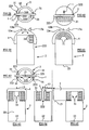
- FIG 18 this illustrates the generation of opposing travelling surface waves in an embodiment of the invention.
- the figure is highly schematic and shows an end surface 21 of a piezoelectric tube.
- a ring of twelve electrodes is arranged around the outer surface of the tube.
- a single, common central electrode may be used, although this not shown in the figure.
- the electrodes are evenly spaced around the circumference of the tube, so as to permit application of electric fields to selected segments of the tube.
- the numbering (1, 2, 3) next to the electrodes illustrates the sequence in which they are excited to generate suitable travelling waves on the surface 21.
- the numbering can also be considered to represent the positions of the peaks of the travelling surface waves at first, second and third points respectively in the wave-generation cycle.
- Application of the control voltages to the twelve electrodes results in a first travelling surface wave travelling in a counter clockwise direction around a first portion 211 of the end surface 21 and, at the same time, the generation of a second travelling surface wave travelling in the clockwise direction around a second portion 212 of the end surface 21.
- the motion of the first travelling surface wave is indicated generally arrow A1 and the motion of the second wave is indicated generally be arrow A2.
- the first and second portions 211, 212 do not overlap, and each represent half of the end surface 21, such that together they comprise the entire end surface 21.
- an object may be supported on the end surface 21, the object having a flat surface arranged in contact with the end surface 21.
- the first and second travelling waves interact with the object surface so as to translate the object in the X direction, without causing any rotation.
- the object may have a spherical surface arranged in contact with the end surface 21. In such cases the travelling waves interact with the spherical surface so as to rotate the body about an axis parallel to the Y axis.
- Figure 19 illustrates the use of the same piezoelectric tube and electrode arrangement from figure 18 to produce travelling waves suitable for moving a supported object in a different direction.
- the electrodes are excited in a different sequence such that the first and second portions 211 and 212 of the end surface along which the travelling waves are generated are diametrically opposed along the X axis, rather than along the Y axis as was the case in figure 18 .
- the numbers 1, 2, 3 next to the electrodes again represent the positions of the peaks of the travelling waves at first, second and third points, respectively, on the cycle.
- the travelling surface waves generated in figure 19 would interact with a flat object surface to translate the object in the negative Y direction of the figure, and would interact with a spherical object surface to rotate the object about an axis parallel to the X axis.
- the generation of the first travelling wave is achieved by appropriate sequential excitation of a first group of electrodes spaced around a section of the tubes circumference
- the second travelling wave is generated by appropriate excitation of a second group of electrodes spaced around a second section of the circumference.
- the first and second groups of electrodes have two electrodes in common (in figure 18 the shared electrodes are the top and bottom electrodes, and in figure 19 the electrodes shared by the groups are those at the extreme left and extreme right).
- the groups of electrodes used to produce the two travelling waves may be completely separate.
- the use of twelve electrodes is particularly advantageous because it allows positioning of a supported object in perpendicular directions.
- the twelve-segment configuration enables translation of the tube in perpendicular directions over the base surface.
- a further advantage of the twelve-electrode configuration shown in figs 18 and 19 is that any time during the wave generation cycle, there are four wave peaks (i.e. high points) for engaging a supported object surface or the surface of a base.
- figs. 20 and 21 These illustrate the use of 10 electrodes (i.e. 10-segment configuration) to generate opposing travelling surface waves along respective portions of the end surface 21 of a tube.
- 10 electrodes i.e. 10-segment configuration
- the frequency of the control voltage cycle can be a slow as one likes without comprising tube,or supported object, stability.
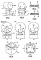
- figs. 22a to 22d show the wave peak positions P at successive times T1, T2, T3 and T4 on the surface of a tube having 12-segment configuration and excited accordingly to the technique illustrated in fig. 19 .
- Figs. 22e to 22h illustrate the rotation of a supported body 1 as a result of interaction with the travelling waves whose peak motions are depicted in figures 22a to 22d .
- the supported body 1 has a spherical first surface 11 which is arranged to rest on the upper surface 21 of the tube.
- the travelling waves are generated, the spherical surface 11 is supported only by the peaks P.
- the travelling waves are such that the tube material motion at the top of each peak is in a direction opposite to the direction of travel of the peak itself.
- the supported body 1 is rotated in a direction indicated generally by arrow R.
- the supported body 1 comprises a mirror 12.
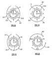
- FIGS. 23 and 24 show the use of a four-segment configuration (i.e. four spaced apart electrodes) to generate first and second travelling waves on the surface of a piezoelectric tube.
- the figures 1 , 2 and 3 next to the electrodes three indicate the sequence of excitation.
- the sequence of electrodes excitations would translate the object in the positive X direction.
- an object having a spherical surface resting on the end surface 21 would be rotated about an axis parallel to the Y direction.
- the movement of a supported object result from the interaction generated in figure 24 would be the same as, that described with reference to figure 19 .
- a four electrode (or 4-segment) configuration is convenient as it uses the same segmentation that is used conventional fine X, Y and Z positioning with piezoelectric tubes. The configuration allows for perpendicular axes of movement
- Figs. 25 and 26 illustrate the use of a 3-segment configuration to generate first and second travelling waves on respective portions of the end surface of piezoelectric tube.
- 3-segment configuration provides the minimum number of segments to provide relative translation or motion between the tube and the surface with which it is in contact, or to provide relative rotation between the tube and a surface with which it is in contact about an axis other than the longitudinal axis of the tube.
- the surface arranged in contact with the end surface may have a variety of shapes.
- the surface may be a surface of an object moved by the tube (e.g. supported by the tube) or alternatively may be a surface (e.g. a base surface) over which the tube moves.
- suitable surfaces include: surfaces with zero curvature in both directions (flat planes); surfaces with zero curvature in one direction and constant, non-zero curvature in another direction (a cylinder); and surfaces with equal non-zero curvatures in two directions (a sphere).
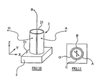
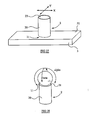
- Fig. 27 illustrates an embodiment of the invention comprising a piezoelectric tube having a flat annular end surface 21 resting on the flat upper surface 51 of a base member 5.
- the base 5 supports the tube.
- a plurality of electrodes are attached to the tube, their arrangement being such that travelling waves may be generated on the end surface 21 by application of a suitable control voltages to the electrodes, those travelling surface waves interacting with the supporting surface 51 to provide controllable translation of the tube 2 over the supporting surface 51.
- the tube can be translated in a first direction parallel to the plans of the supporting surface 51 (i.e.
- the X direction in the figure can be controlled to provide controllable movement in a second perpendicular direction parallel to the supporting surface (i.e. the Y direction in the figure).
- caterpillar-type motion can be achieved.
- the tube is able to "walk" over the supporting surface 51 whilst remaining upright.
- the tube 2 is pressed against the flat supporting surface 51 by gravity alone.
- biassing means may be arranged to urge the end surface 21 and the supporting surface 51 together. The tube may then be arranged to walk over a non-horizontal surface.
- the electrode arrangement is not shown in figure 27 , it will be appreciated that a variety of electrode arrangements may be employed, utilising combinations of electrodes, positioned on the outer surface 20 and/or the inner surface 23 of the tube.
- the tube By continuing to generate the first and second travelling waves on the end surface 21 of the tube, the tube continues to "walk" over the supporting surface 51.
- large movements can be achieved in the X and Y directions.
- the arrangement of figure 27 can thus be utilised in positioning apparatus to achieve coarse motion in two directions.
- this shows an alternative embodiment of the invention in which a spherical object 1 is pressed against the end surface 21 of the tube.
- the object 1 is thus supported by the tube.
- a plurality of electrodes are arranged on the tube so as to permit generation of travelling surface waves on the upper surface 21 using techniques described above.
- an array of 12 electrodes may be used to generate surface waves which interact with the sphere 1 to produce independent rotation control about two mutually perpendicular axis which are themselves perpendicular to the longitudinal axis of the tube. These independent rotations are labelled alpha and beta in the figure.
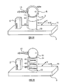
- the apparatus comprises a base 5 and a sample S mounted on the base.
- a tube 2 of piezoelectric material is supported by the base 5, with a lower end surface 22 of the tube resting on the flat base surface 51.
- An upper end surface 21 of the tube supports a moveable body comprising a sphere 1 and a cantilever 13 fixed to and extending from the sphere.
- the sphere provides a spherical operational surface 11 which is in contact with the upper end surface 21 of the tube.
- a top longitudinal end portion 41 of the tube is provided with a first array of electrodes, the first array being arranged such that opposing travelling surface waves can be generated on the upper surface by application of suitable control voltages, as described above.
- a lower longitudinal end portion 43 of the tube is provided with a second array of electrodes, arranged such that opposing travelling surface waves can be generated on the lower end surface 22 by application of appropriate control voltages, also as described above.
- the top and bottom parts 41, 43 of the tube are segmented independently.
- a controller (not shown in the figure) provides control voltages to the electrodes on the top longitudinal segment 41 so as to generate travelling surface waves on surface 21 and provide controllable rotation of the sphere 1 in the direction indicated generally by arrow R. This corresponds to rotation of the sphere about an axis parallel to the Y axis in the figure. As the sphere is rotated in this way, the tip of the cantilever is moved, that movement including motion in the Z direction.
- the cantilever fixed to the to the sphere converts the angular motion of the supported sphere into coarse Z motion of the cantilever tip.
- the controller is also arranged to generate travelling surface waves on the lower end surface 22 to provide controlled translational movement of the tube 2 over the supporting base surface 51 in the X and Y directions.
- control of the electrodes on the lower longitudinal segment 43 is able to provide coarse motion of the cantilever tip in the X and Y directions
- control of the electrodes of the upper longitudinal end portion 41 is able to provide coarse Z motion control of the cantilever tip by rotating the sphere.
- the controller may be further arranged to apply suitable control voltages to the electrodes of both the top and bottom longitudinal portions 41, 43 to provide controllable bending of the tube 2 and controlled elongation or shrinkage of the tube along the Z axis, so as to provide fine X, Y & Z movement of the upper surface 21 and hence of the cantilever tip connected to the supported sphere.
- the apparatus is able to provide both a fine and coarse positioning of the tip in all three directions X Y and Z relative to the sample S. This fine and coarse positioning control in all three directions has been conveniently achieved with only a small number of components.
- the simplicity, small size, and small mass of the apparatus provides significant advantages over the prior art positioning techniques.
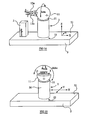
- a piezoelectric tube is supported by a base 5 and itself supports a sphere carrying a cantilever 13 (which may also be described as a probe).
- fine motion control in the X, Y and Z directions is achieved by means of application of suitable control voltages to a plurality of electrodes attached to a central longitudinal portion 42 of the tube.
- a separate set of electrodes is arranged on the upper end segment 41 to generate the travelling waves necessary to provide controlled rotation of the supported sphere, and another plurality of the electrodes is arranged on the lower end segment 43 to generate the travelling waves required to provide translation of the tube over the supporting surface 51.
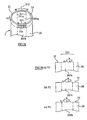
- An example of a piezoelectric tube and electrode arrangement suitable for use in the apparatus depicted in fig. 30 is shown in fig. 31 .
- the tubular member comprises a cylindrical tube of piezoelectric material, the tube having a circular cross section.
- the material of the tube is poled in the radial direction, as indicated by the short arrows P on the upper end surface 21.
- the upper end surface 21 is annular and flat.
- the tube has a second annular, flat end surface 22 at its opposite end.
- the top longitudinal section 41 of the tube is provided with an array of twelve electrodes 31 evenly spaced around the circumference (i.e. perimeter) of the tube on its outer surface 20.
- a schematic cross section of this top end portion 41 of the tube and the twelve-electrode arrangement is shown in figure 33 .
- the electrodes divide the top portion of the tube into 12 segments, and they be excited by control voltages using techniques as described above in order to generate travelling surface waves on the upper end surface 21.
- the 12 electrodes in the upper end portion may be excited in a variety of ways, for example, to provide two or more travelling surface waves on the end surface.
- the travelling surface waves need not necessarily travel around a full half of the end surface.
- diametrically opposed groups of three electrodes may be exited to generate first and second travelling ways, each of which travels around just one quarter of the end surface.
- a bottom end segment 43 of the tube is provided with a similar arrangement of twelve electrodes 33 which can be excited to generate travelling waves on the bottom end surface 22 using the same techniques as those used to produce the waves on the upper surface 21.
- the upper set of electrodes 31 can be used to generate travelling waves on the upper surface 21 to translate and/or rotate a supported body whilst the lower set of electrodes 33 can be used to generate travelling waves on the lower surface 22 to provide separate, i.e. independent control of translational movement of the tube over a surface on which it is supported.
- the lower set of electrodes can be controlled in another way to produce rotation of the tube about the Z axis. To achieve this, rather than generating opposing travelling waves along respective portions of the lower surface, the electrodes could be used to generate one or more travelling waves on the lower surface which travel in the same direction around it.
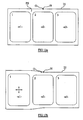
- the central longitudinal segment 42 of the tube of fig. 31 is provided with an array of four larger electrodes 32.
- a common voltage may be applied to all four of these electrodes 32 to control elongation or shrinkage of the tube in the Z direction (i.e. to provide fine Z control of the position of the upper surface 21).
- a differential voltage may be applied between a first diametrically opposed pair of these electrodes 32a to provide controllable bending of the tube in one direction and thus provide fine movement control of the end surface 21 in, say, the nominal X direction.
- a differential voltage may be applied between the second opposing pair 32b of central portion electrodes to achieve bending in an orthogonal direction, to provide fine control of the Y position of the end surface 21 for example.
- three different groups of electrodes are employed to provide independent control of movement of a body supported on the top surface 21, movement of the tube itself over a supporting surface, and bending and elongation of the tube itself. If the tube is used to support a body carrying a probe, for example, then fine X, Y and Z motion of a probe tip can be achieved independently from coarse X, Y and Z motion.
- Fig. 34 shows positioning apparatus in accordance with an alternative embodiment of the invention.
- the electrode arrangement on the tube 2 is not shown.
- an electrode arrangement such as that shown in fig. 31 may be employed.
- the moveable member 1 supported by the tube 2 comprises two cantilevers 13a and 13b. They are fixed to the spherical portion of the body 1.
- the moveable member may be rotated by suitable generation of travelling waves on the upper surface 21 to bring one or the other of the cantilevers close to the sample S. This arrangement gives the possibility to choose between two different cantilevers or to change a broken or contaminated cantilever quickly.
- one cantilever can hold an atomic force microscopy tip, while the other can hold a scanning tunnelling microscopy tip.
- the moveable members supported on the tube may comprise one, two or even more cantilevers, probes, tips or the like.
- the moveable member (such as a lens) can hold a carousel of, say, ten probes.
- Fig. 35 shows alternative positioning apparatus embodying the invention.
- the piezoelectric tube 2 supports a body having a hemispherical surface 11 in contact with the upper surface 21 of the tube, and an upper flat surface 14 arranged to support a sample S.
- the supported body 1 is a rotatable sample stage.
- the tube may be provided with an electrode arrangement in accordance with the techniques described above.
- travelling waves may be generated on the upper surface 21 to control tilt of the sample in the orthogonal directions denoted by arrows alpha and beta in the figure.
- the electrode arrangement is such that travelling waves can be generated on the lower end surface 22 of the tube to provide translation of the tube relative to the base 5 and hence provide coarse X and Y positioning of the supported sample.
- the electrode arrangement also provides for fine control of the X, Y and Z position of the sample by providing controllable elongation of the tube and controllable bending.
- Fig. 3 shows an alternative electrode arrangement for producing travelling surface waves 211 and 212 on the end surface 21 of a tube of piezoelectric material in embodiments of the invention.
- the electrodes 31 are confined to azimuthal segments 201a and 201b.
- the electrodes are also confined to an end longitudinal segment 41 of the tube, i.e. they are arranged close to the surface 21 on which they are used to generate travelling surface waves.
- the electrodes comprise a first group of six electrodes 31b which extend around the first azimuthal segment 201b. Thus they are arranged adjacent the first portion 211 of the end surface 21. This first array of electrodes 31b is arranged on the outer surface 20 of the tube.
- a corresponding common electrode 311b is arranged on the inner surface 23 of the tube, again extending around the first azimuthal segment 201b.
- a second group of outer surface electrodes 31a and a corresponding inner surface electrode 311 a are arranged on the longitudinal end section 41 of the tube at a position diametrically opposed to that of the first group.
- Fig 37 is a schematic end view, looking along the longitudinal axis, of the tube and electrode arrangement from figure 36 , and the numbers 1, 2, and 3 next to the outer surface electrodes generally represent an excitation sequence.
- the numbers 1, 2 and 3 denote the positions of the peaks of travelling surface waves generated on the first and second portions 211 and 212 of the upper surface 21 at successive times in the wave generation cycle.
- the first azimuthal segment 201b has an angular extent B which is the same as the angular extent A of the second azimuthal segment 201 a.
- these angles A and B are not necessarily the same.
- the rows of electrodes shown in figures 36 and 37 can thus be controlled by a three phase supply to generate a first travelling wave which travels in the clockwise direction along portion 211 of the upper surface, and at the same time to generate a second travelling wave which travels in the counter clockwise direction along portion 212.
- these travelling waves may each comprise two peaks P at any one time.
- Figures 38a to 38c are highly schematic illustration of the motion of these peaks at three successive times in the wave generation cycle.
- the first and second travelling surface waves do not travel around the entire end surface, but instead only travel around relatively short, diametrically opposed sections of that surface.
- This technique is able to provide translation of a flat surface supported by the tube, or rotation of a supported object about an axis other than the longitudinal axis of the tube.
- it provides the additional advantage that it reduces wear between the supporting surface 21 and the supported surface because the components of the first and second travelling waves which try to push a supported surface in opposite directions are only small.
- first and second travelling waves are generated around respective halves of the end surface, in which, at the points where the halves meet, the travelling waves are trying to push a supported surface in completely opposite directions.
- Figs 39 to 42 these illustrate an alternative apparatus in which a sheet 2 of piezoelectric material is used rather than a piezoelectric tube.
- the sheet 2 has one end coupled to a supporting surface 51, and supports a movable cylindrical member 1 on an upper end surface 21.
- the upper end surface 21 is cylindrical so as to conform with the cylindrical outer surface 11 of the supported body 1.
- a plurality of electrodes 31 is arranged on an upper end portion 41 of the sheet, close to the upper end surface 21. Control voltages are applied to these electrodes 31 to generate travelling surface waves on the upper end surface 21 and rotate the body 1 about rotational axis RA.
- Electrodes 32 are arranged on opposite sides of the sheet 2, closer to the support surface 51, and control voltages may be applied between these electrodes 32 to achieve bending of the sheet to move the supported surface 21 (and hence the supported cylinder) along the rotational axis RA and to provide controlled elongation and shrinkage of the sheet 2 in the vertical direction of the figure, that is in a direction perpendicular to the rotational axis RA.
- the lower electrodes 32 can be used to provide fine positioning of the supported cylinder in two mutually perpendicular directions, and control of the upper set of electrodes 31 can be used to control rotation of the cylinder.
- the material of the sheet is poled in a direction P which is normal to the front and rear faces 28, 29.
- Figs 43a to 43c illustrate the sequential excitation of the upper set of electrodes 31 to produce a travelling wave on the surface 21 which has two peaks P.
- These travelling waves are Rayleigh surface waves.
- the direction of propagation of the waves is denoted by the arrow on the front face 28 of the body, and interaction between the material at the wave peaks P and the cylinder is such that the cylinder is rotated in the direction shown by arrow R.
- Figs 44 and 45 show a tubular piezoelectric member and electrode arrangement suitable for use in alternative embodiments of the invention.
- the cross section of the tube in this example is generally square and the upper end surface 21 is adapted to provide a seat for a cylindrical surface.
- Each outer face of the tube is provided with a respective line of electrodes 31 positioned close to the top edge, (i.e. adjacent to the upper surface 21).
- travelling waves can be generated on the corresponding portions of the upper surface 21 to rotate the supported cylindrical surface about its longitudinal axis.
- Independent control of movement of the supported cylindrical surface in a direction parallel to its longitudinal axis can be achieved by application of suitable control voltages to the sets of electrodes 31 c and 31d on the other pair of sides of the tube.
- FIG 46 this illustrates alternative positioning apparatus embodying the invention.
- a spherical body 1 is supported by a cylindrical piezoelectric tube 2 which is itself supported by a base 5.
- the upper end surface of the tube is provided with a coating or layer of wear-resistant material 210. It is a surface of this material 21 against which the spherical body sits.
- the spherical body is also provided with an outer coating or layer of wear-resistant material 110, and the operational surface 11 of the spherical body 1 is hence a surface of this coating or layer 110.
- the upper seating surface 21 is shaped so as to conform with the portion of the spherical surface 11 with which it engages.
- An anchor member 70 is rigidly fixed inside the tube 2 and the spring 71 is connected between this anchor member 70 and the supported body 1 so as to bias the operational surface 11 against the supporting surface 21.
- the sphere is pulled down onto the tube.
- a lower end surface of the tube comprises another coating or layer of wear-resistant material 220 which rests on a wear-resistant coating 501 which provides the upper supporting surface 51 of a base 5.
- a magnet 72 is attached to the anchor member 70 and the base 5 comprises ferrous material such that the attraction between the magnet and base hold the tube and base together. Thus, the positioning apparatus need not be used in the horizontal configuration.
- the piezoelectric tube is provided with an electrode arrangement of the type described with reference to Figure 31 , and a control system 6 provides suitable control voltages 61 to the electrodes of the upper, middle and lower longitudinal sections of the tube so as to the provide controlled rotation of the supported body and translation of the tube over the base 5.
- FIG. 47 this is a highly schematic illustration of another embodiment of the invention in which a piezoelectric tube is arranged to "walk" over the spherical surface 11 of a body 100. This relative movement is achieved by appropriate application of control voltages to an electrode arrangement on the piezoelectric tube.
- the control voltages 61 are provided by controller 6, and the electrode arrangement is generally indicated by reference numeral 30.
- the arrangement is such that travelling waves are generated on the surface of the tube in contact with the body 100 using techniques described above.
- Fig. 48 is a highly schematic representation of an articulated manipulation apparatus embodying the invention.
- This apparatus comprises a first piezoelectric tube 2a supported on a support surface 51.
- a first sphere 1ab is supported on first tube 2a, and it self supports a second piezoelectric tube 2b.
- a second sphere 1bc is supported on the second tube 2b, and itself supports a third tube 2c.
- Each of the tubes is provided with a respective electrode arrangement 30a, 30b, 30c, the arrangements being such that application of suitable control voltages from a controller 6 are able to generate travelling surface waves independently at each end of each tube.
- Fig. 49 illustrates an alternative arrangement of piezoelectric members useful for understanding the invention.
- This arrangement comprises four slabs of piezoelectric material 2a, 2b, 2c and 2d.
- the upper surfaces 21 of the members provide support for a moveable member.
- Each slab is provided with a lower electrode arrangement 33 for generating travelling surface waves along a lower end surface.
- Each slab is provided with a central electrode arrangement 32 for providing controlled bending of the slab and controlled elongation and shrinkage in the vertical direction in the figure.
- Each slab is also provided with an upper electrode arrangement 31 which can be controlled to generate travelling surface waves along the upper surfaces.
- a flat body can be supported on the upper surfaces and travelling waves can be generated on the upper surfaces 21a and 21b to translate the object in one direction, and then travelling waves can be generated on surfaces 21 c and 21 d to move the supported object in a perpendicular direction.
- Fig. 50 illustrates an alternative tubular member for use in embodiments of the invention.
- This tube has a composite structure in that it comprises segments 201 of piezoelectric material and segments 200 of non-piezoelectric material.
- the piezoelectric segments may be provided with electrode arrangements as described above to generate travelling surface waves on portions of the upper surface corresponding to those piezoelectric segments.
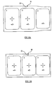
- Fig. 51 illustrates a piezoelectric tube 2 and electrode arrangement for use in embodiments of the invention.
- An upper portion 41 of the tube is provided with an outer ring electrode 320 on its outer surface 20, and an inner ring electrode 323 on its inner surface 23.
- These ring electrodes 320, 323 are thus concentric, and are used to provide fine control of elongation of the tube.
- appropriate voltages may be applied between the inner and outer circular electrodes 320,323 to adjust the longitudinal position of the upper end surface 21 with respect to the lower end surface 22.
- a lower segment 43 of the tube is segmented by a plurality of electrodes 33 (four of them, in this example). These lower electrodes are controlled to provide controlled bending of the tube and to generate travelling waves on the lower end surface 22.
- a variety of suitable electrode arrangements for the inner surface of the lower segment will be apparent from the preceding description.
- Fig. 52 illustrates an alternative tube and electrode arrangement.
- the inner surface 23 is segmented by four inner electrodes 310, each of which extends along both upper and lower portions 41, 43 of the tube.
- an upper portion 41 is segmented by one group of electrodes 31, and the lower portion 43 is segmented in the same way by a second group 33.
- Control voltages may be applied to the electrodes in a variety of ways, as will be appreciated from the preceding description.
- the inner electrodes 310 may be held at a common potential, whilst the electrodes 31 of the upper group are excited in an appropriate sequence.
- travelling waves on the lower surface may be generated by excitation of the lower group of electrodes 33, with the inner electrodes held constant.
- a common potential may be applied between the inner and outer electrodes.
- differential voltages may be applied between opposing pairs of the inner electrodes 310, and/or opposing pairs or opposing groups of the outer electrodes 31,33.
- the different modes of deformation and wave generation may, of course, be combined simultaneously, by appropriate application of control voltages.
- the voltage applied to a particular electrode at a particular time may thus comprise a number of different components.
- a piezoelectric tube is used for 6 degrees of freedom: coarse positioning X, Y, Z and fine positioning X, Y, Z.
- coarse X and Y movements are achieved by means of at least 3 independently driven sectors located close to one edge of the tube. Sequential application of electric driving voltage to these sectors results in a caterpillar-like motion of the edge.
- the tube may be placed on a fixed flat surface and pressed against it by gravity, by a spring, by magnetic force or by vacuum suction, can walk on it in the direction determined by the caterpillar motion.
- Coarse Z movement can be achieved by means of at least 3 independently driven sectors located close to another edge of the tube. Sequential application of electric driving voltage to these sectors results in a caterpillar-like motion of the edge.
- a sphere or object having partially spherical shape e.g., a lens placed on the edge of the tube and pressed against it by gravity, a spring, magnetic force or vacuum suction can rotate in the direction determined by the caterpillar motion.
- a cantilever (beam, wing, whisker) attached to the sphere converts the rotation into Z coarse motion of its end.
- Fine X, Y and Z control may be achieved by means of a middle part of the tube segmented by any of the ways used conventionally for piezoelectric tube fine movement (3 or more independently driven sectors). Alternatively fine positioning can be achieved by the same sectors used for coarse X and Y or those used for coarse Z motion.
- aspects of the invention include using a piezoelectric tube to move objects laterally, the object having surface of a constant curvature in one direction and a constant curvature in another direction.
- These include lateral movement of a flat surface and a polar rotation of a sphere.
- a hemisphere or a lens put on the tube can serve to tilt a sample. This is particularly useful for positioning of a sample in a Scanning Electron Microscope.
- aspects also provide manipulation/positioning devices capable of rotation and linear translation of at least one supported body (of partially flat, cylindrical or spherical shape), or of moving against such a body.
- the active part of certain devices embodying the invention is a tube made of a piezoelectric material, and two deformation waves are excited in the cylinder by means of electrodes on its inner and outer sides. The waves deform an edge of the tube in a caterpillar way. The body translated or being translated against is engaged against the cylinder edge by friction.
- micro-manipulators may be described as micro-manipulators, nano- manipulators, positioning devices, and actuators.
- Embodiments find a wide variety of applications, for example in Scanning Tunnelling Microscopes, Atomic Force Microscopes, and nanomanipulator systems.
- FIG. 53 that figure is a schematic representation of another tubular piezoelectric body 2 suitable for use in embodiments of the invention.
- the body 2 has a first end surface 21 which, rather than being substantially flat, is provided with a plurality of slots or grooves.
- the end surface 21 can be regarded as generally castellated.
- the number of grooves around the tube's circumference (12) is equal to the number of electrodes around the circumference.
- the number of grooves may be a non-unity multiple of the number of electrodes.
- the grooves in alternative embodiments may have different shapes.
- the patterned end surface enables debris and contaminants to be trapped in the grooves, such that the lands between adjacent grooves may be kept clean.
- a movable member may thus be supported on the lands of the upper surface 21, and moved relative to the tubular body by means of travelling surface waves generated on the lands by application of suitable control voltages to the electrodes 31 of the upper portion 41 of the tube.
- the lower end surface 22 of the tube is similarly patterned, and travelling surface waves may be generated on the lower surface by application of control voltages to the electrodes 33 of the lower portion 43.
- the probe-positioning apparatus includes a piezoelectric body 2 which is generally tubular, and at least one of the tube ends has a pair of opposite slits 222.
- a movable member 1 in the form of a flat plate carries a probe 13 and is received in the pair of slits (slots) 222. Surfaces of the plate 1 are engaged against operational surfaces 223 of the body 2 (these operational surfaces are side surfaces of the slots, i.e. they are provided by the slit walls) by springs in this example.
- Electrodes 71 each engage a non-operational surface 224 of a respective slit 222 and urge the plate 1 against the operational surface 223 on the opposite side of the slit.
- springs are illustrated, it will be appreciated that other biasing means, for example using magnetic force, may be used in alternative embodiments.
- electrodes are arranged along both slits. These comprise a plurality of external electrodes 31 on the outer surface 20 of the tube, adjacent the operational side surfaces of each slit, and a corresponding plurality of electrodes 310 arranged on the inner surface of the tube, again adjacent the operational side surfaces of the slits.
- the plate By applying sequential voltages to the electrodes and generating two waves (one on each operational surface 223) travelling in the same direction (i.e. both travelling up, or both travelling down) the plate is moved in the longitudinal direction (vertical in this example).
- the lower end surface 22 of the body 2 may be supported on a base, and thus control of voltages applied to the electrodes adjacent the operational surfaces may be used to generate travelling surface waves of the Rayleigh-type to provide controlled movement of the plate 1, and probe 13, towards or away from the base.
- the body 2 may also be provided with a plurality of electrodes adjacent the lower surface 22 to enable generation of travelling surface waves on the lower surface to translate or rotate the body with respect to the base.
- Further electrodes may be provided on the body, as described above, to provide controlled distortion and hence fine positional control of the supported plate 1 in the X, Y and Z directions.
- the configuration depicted in figs. 54 and 55 with springs 71 arranged at opposite sides of the plate, benefits from the symmetry with respect to the tube central axis. This symmetry is crucial for stability (e.g. thermal drift) on a nanometre scale.
- configurations with springs or a spring arranged on only one side would also work
- differently shaped plates and slits i.e. other than flat can be used in embodiments of the invention.
- Figs. 56 and 57 illustrate apparatus in which the movable member 1 is a curved plate (i.e. it can be regarded as a section of a cylinder)
- Apparatus incorporating a kettle-shaped piezoelectric body 2 is shown in figs. 60 and 61 .
- Electrodes 31 are arranged on an "upper" domed end of the body, alongside the operational surface 223 of a slot 222 in the end.
- a movable member 1 carrying probes 13a-c is received inside the slot 222 and a spring 71 inside the hollow body urges the member 1 against the operational surface 223.
- the member 1 can be made to perform rotation or translation depending on the direction of the travelling wave or waves generated by application of voltages to the electrodes 31.
- the width of the slit can be slightly (5-50micron) less than the width of the plate. Then the plate can be held without requiring springs. In this case it is not easy to adjust the friction force. However, in contrast to slip-stick techniques, the travelling wave principle used in embodiments of the invention does not depend so strongly on the friction.
- One of the shapes of piezoelectric body better accommodating stress in this case is depicted in figures 62-64 .
- the movable member 1 forms an interference fit in the slots 222, and is thus tightly held.
- each slit thus provide operational surfaces, on which travelling waves are generated by a generation system including external electrodes 31 on either side of each slit
- the lower surface 22 of the body 2 can be supported on a base (over which it may be controlled to ""walk"), and interaction between the travelling waves on the four operational surfaces 223 and the movable member 1 can be used to provide coarse positional control of the probe 13 towards and away from the base.
- a distortion control system may be employed (including further electrodes and control voltage application means) to provide controlled distortion (e.g. elongation and/or bending) of the body, and hence fine positional control of the probe (which can also be referred to as a tool, tip, cantilever etc).
- Fig 65 depicts a similar apparatus to that shown in figs. 62-64 , but with a laterally extended movable member (plate) carrying a tip directed downwards, i.e. towards the base surface 22 of the body.
Landscapes
- Physics & Mathematics (AREA)
- Health & Medical Sciences (AREA)
- General Health & Medical Sciences (AREA)
- General Physics & Mathematics (AREA)
- Nuclear Medicine, Radiotherapy & Molecular Imaging (AREA)
- Radiology & Medical Imaging (AREA)
- Chemical & Material Sciences (AREA)
- Engineering & Computer Science (AREA)
- Nanotechnology (AREA)
- Analytical Chemistry (AREA)
- Crystallography & Structural Chemistry (AREA)
- General Electrical Machinery Utilizing Piezoelectricity, Electrostriction Or Magnetostriction (AREA)
- Microscoopes, Condenser (AREA)
- Control Of Position Or Direction (AREA)
- Shaping Of Tube Ends By Bending Or Straightening (AREA)
- Auxiliary Devices For And Details Of Packaging Control (AREA)
- Die Bonding (AREA)
Applications Claiming Priority (2)
| Application Number | Priority Date | Filing Date | Title |
|---|---|---|---|
| GB0508911A GB2425882A (en) | 2005-04-29 | 2005-04-29 | Positioning apparatus |
| PCT/GB2006/001564 WO2006117525A2 (en) | 2005-04-29 | 2006-04-27 | Positioning apparatus and method |
Publications (2)
| Publication Number | Publication Date |
|---|---|
| EP1880467A2 EP1880467A2 (en) | 2008-01-23 |
| EP1880467B1 true EP1880467B1 (en) | 2012-03-14 |
Family
ID=34674186
Family Applications (1)
| Application Number | Title | Priority Date | Filing Date |
|---|---|---|---|
| EP06726944A Not-in-force EP1880467B1 (en) | 2005-04-29 | 2006-04-27 | Positioning apparatus and method |
Country Status (6)
| Country | Link |
|---|---|
| US (1) | US8179019B2 (enExample) |
| EP (1) | EP1880467B1 (enExample) |
| JP (1) | JP2008539486A (enExample) |
| AT (1) | ATE549790T1 (enExample) |
| GB (1) | GB2425882A (enExample) |
| WO (1) | WO2006117525A2 (enExample) |
Families Citing this family (2)
| Publication number | Priority date | Publication date | Assignee | Title |
|---|---|---|---|---|
| JP5458300B2 (ja) * | 2009-02-09 | 2014-04-02 | 公立大学法人横浜市立大学 | 微細構造物の蒸着装置及び方法 |
| CN115411968B (zh) * | 2022-07-25 | 2025-08-29 | 中国科学院合肥物质科学研究院 | 双压电管并排惯性驱动的旋转马达及旋转扫描探针显微镜 |
Family Cites Families (11)
| Publication number | Priority date | Publication date | Assignee | Title |
|---|---|---|---|---|
| US4893047A (en) * | 1988-09-20 | 1990-01-09 | Honda Electronic Co., Ltd. | Ultrasonic driving device |
| US5051646A (en) * | 1989-04-28 | 1991-09-24 | Digital Instruments, Inc. | Method of driving a piezoelectric scanner linearly with time |
| EP0789937B1 (de) * | 1994-10-31 | 2000-05-17 | Pi Ceramic GmbH | Piezoelektrischer motor |
| GB9617076D0 (en) | 1996-08-14 | 1996-09-25 | Intelligent Manufacturing Syst | Bearings and supports |
| US6252333B1 (en) * | 1998-02-20 | 2001-06-26 | Seiko Instruments Inc. | Stage utilizing ultrasonic motor and electronic equipment and printer utilizing the stage |
| US6778509B1 (en) | 1999-11-19 | 2004-08-17 | Hughes Electronics Corporation | MAC layer protocol for a satellite based packet switched services |
| DE10154526B4 (de) * | 2001-06-12 | 2007-02-08 | Physik Instrumente (Pi) Gmbh & Co | Piezoelektrisches Stellelement |
| JP2004140946A (ja) | 2002-10-18 | 2004-05-13 | Canon Inc | アクチュエータ |
| DE10314810A1 (de) * | 2003-01-08 | 2004-08-05 | Physik Instrumente (Pi) Gmbh & Co. Kg | Verfahren zum Betreiben eines piezoelektrischen Motors sowie piezoelektrischer Motor mit einem Stator in Form eines hohlzylindrischen Oszillators |
| US6993342B2 (en) | 2003-05-07 | 2006-01-31 | Motorola, Inc. | Buffer occupancy used in uplink scheduling for a communication device |
| US20050053035A1 (en) | 2003-08-16 | 2005-03-10 | Samsung Electronics Co., Ltd. | Method and apparatus for providing uplink packet data service on uplink dedicated channels in an asynchronous wideband code division multiple access communication system |
-
2005
- 2005-04-29 GB GB0508911A patent/GB2425882A/en not_active Withdrawn
-
2006
- 2006-04-27 JP JP2008508303A patent/JP2008539486A/ja not_active Withdrawn
- 2006-04-27 WO PCT/GB2006/001564 patent/WO2006117525A2/en not_active Ceased
- 2006-04-27 EP EP06726944A patent/EP1880467B1/en not_active Not-in-force
- 2006-04-27 AT AT06726944T patent/ATE549790T1/de active
- 2006-04-27 US US11/919,291 patent/US8179019B2/en not_active Expired - Fee Related
Also Published As
| Publication number | Publication date |
|---|---|
| ATE549790T1 (de) | 2012-03-15 |
| JP2008539486A (ja) | 2008-11-13 |
| GB2425882A (en) | 2006-11-08 |
| GB0508911D0 (en) | 2005-06-08 |
| US8179019B2 (en) | 2012-05-15 |
| WO2006117525A3 (en) | 2007-03-29 |
| WO2006117525A2 (en) | 2006-11-09 |
| EP1880467A2 (en) | 2008-01-23 |
| US20100117486A1 (en) | 2010-05-13 |
Similar Documents
| Publication | Publication Date | Title |
|---|---|---|
| US6437485B1 (en) | Double bimorph electromechanical element | |
| Tahmasebipour et al. | A novel high performance integrated two-axis inchworm piezoelectric motor | |
| Fujita | Microactuators and micromachines | |
| US7557470B2 (en) | 6-axis electromagnetically-actuated meso-scale nanopositioner | |
| Zhang et al. | Development of a cross-scale 2-DOF piezoelectric rotary platform based on active friction switching | |
| US6337532B1 (en) | Fine walking actuator | |
| US20030038558A1 (en) | Micro-actuator and method of manufacturing the actuator | |
| Liu et al. | Development of a four-feet driving type linear piezoelectric actuator using bolt-clamped transducers | |
| EP1310038B1 (en) | Walking actuator | |
| EP1350275B1 (en) | Double electromechanical element | |
| Pan et al. | A review of stick–slip nanopositioning actuators | |
| JP2007505329A (ja) | 走査型プローブ顕微鏡 | |
| JPH0744857B2 (ja) | 圧電回転装置 | |
| EP1880467B1 (en) | Positioning apparatus and method | |
| Chen et al. | Development and test of a multimode piezomotor with active contact force adjusting | |
| US6459190B1 (en) | Switched actuator control | |
| US7057746B2 (en) | Scanner for precise movement and low power consumption | |
| Zhou et al. | A novel linear ultrasonic motor with characteristic of variable mode excitation | |
| Bergander et al. | Development of miniature manipulators for applications in biology and nanotechnologies | |
| Su et al. | Implementation of cross-scale plane micro-scratching process driven by hybrid piezoelectric actuation | |
| JP2001305036A (ja) | 微小領域走査装置および走査型プローブ顕微鏡 | |
| US9293685B2 (en) | Rotating load bearer | |
| CN101808181A (zh) | 一种谐振驱动旋转扫描系统 | |
| JP3825591B2 (ja) | 微小領域走査装置 | |
| Ceponis et al. | Development of a Novel 2-DOF Rotary–Linear Piezoelectric Actuator Operating under Hybrid Bending–Radial Vibration Mode. Micromachines 2021, 12, 728 |
Legal Events
| Date | Code | Title | Description |
|---|---|---|---|
| PUAI | Public reference made under article 153(3) epc to a published international application that has entered the european phase |
Free format text: ORIGINAL CODE: 0009012 |
|
| 17P | Request for examination filed |
Effective date: 20071127 |
|
| AK | Designated contracting states |
Kind code of ref document: A2 Designated state(s): AT BE BG CH CY CZ DE DK EE ES FI FR GB GR HU IE IS IT LI LT LU LV MC NL PL PT RO SE SI SK TR |
|
| DAX | Request for extension of the european patent (deleted) | ||
| 17Q | First examination report despatched |
Effective date: 20090925 |
|
| GRAP | Despatch of communication of intention to grant a patent |
Free format text: ORIGINAL CODE: EPIDOSNIGR1 |
|
| GRAS | Grant fee paid |
Free format text: ORIGINAL CODE: EPIDOSNIGR3 |
|
| RAP1 | Party data changed (applicant data changed or rights of an application transferred) |
Owner name: NANOMOBILE LTD. |
|
| GRAA | (expected) grant |
Free format text: ORIGINAL CODE: 0009210 |
|
| AK | Designated contracting states |
Kind code of ref document: B1 Designated state(s): AT BE BG CH CY CZ DE DK EE ES FI FR GB GR HU IE IS IT LI LT LU LV MC NL PL PT RO SE SI SK TR |
|
| REG | Reference to a national code |
Ref country code: GB Ref legal event code: FG4D |
|
| REG | Reference to a national code |
Ref country code: CH Ref legal event code: EP Ref country code: AT Ref legal event code: REF Ref document number: 549790 Country of ref document: AT Kind code of ref document: T Effective date: 20120315 |
|
| REG | Reference to a national code |
Ref country code: IE Ref legal event code: FG4D |
|
| REG | Reference to a national code |
Ref country code: DE Ref legal event code: R096 Ref document number: 602006028175 Country of ref document: DE Effective date: 20120510 |
|
| REG | Reference to a national code |
Ref country code: NL Ref legal event code: VDEP Effective date: 20120314 |
|
| PG25 | Lapsed in a contracting state [announced via postgrant information from national office to epo] |
Ref country code: LT Free format text: LAPSE BECAUSE OF FAILURE TO SUBMIT A TRANSLATION OF THE DESCRIPTION OR TO PAY THE FEE WITHIN THE PRESCRIBED TIME-LIMIT Effective date: 20120314 |
|
| LTIE | Lt: invalidation of european patent or patent extension |
Effective date: 20120314 |
|
| PG25 | Lapsed in a contracting state [announced via postgrant information from national office to epo] |
Ref country code: FI Free format text: LAPSE BECAUSE OF FAILURE TO SUBMIT A TRANSLATION OF THE DESCRIPTION OR TO PAY THE FEE WITHIN THE PRESCRIBED TIME-LIMIT Effective date: 20120314 Ref country code: LV Free format text: LAPSE BECAUSE OF FAILURE TO SUBMIT A TRANSLATION OF THE DESCRIPTION OR TO PAY THE FEE WITHIN THE PRESCRIBED TIME-LIMIT Effective date: 20120314 Ref country code: GR Free format text: LAPSE BECAUSE OF FAILURE TO SUBMIT A TRANSLATION OF THE DESCRIPTION OR TO PAY THE FEE WITHIN THE PRESCRIBED TIME-LIMIT Effective date: 20120615 |
|
| REG | Reference to a national code |
Ref country code: AT Ref legal event code: MK05 Ref document number: 549790 Country of ref document: AT Kind code of ref document: T Effective date: 20120314 |
|
| PG25 | Lapsed in a contracting state [announced via postgrant information from national office to epo] |
Ref country code: CY Free format text: LAPSE BECAUSE OF FAILURE TO SUBMIT A TRANSLATION OF THE DESCRIPTION OR TO PAY THE FEE WITHIN THE PRESCRIBED TIME-LIMIT Effective date: 20120314 |
|
| PG25 | Lapsed in a contracting state [announced via postgrant information from national office to epo] |
Ref country code: PL Free format text: LAPSE BECAUSE OF FAILURE TO SUBMIT A TRANSLATION OF THE DESCRIPTION OR TO PAY THE FEE WITHIN THE PRESCRIBED TIME-LIMIT Effective date: 20120314 Ref country code: SE Free format text: LAPSE BECAUSE OF FAILURE TO SUBMIT A TRANSLATION OF THE DESCRIPTION OR TO PAY THE FEE WITHIN THE PRESCRIBED TIME-LIMIT Effective date: 20120314 Ref country code: RO Free format text: LAPSE BECAUSE OF FAILURE TO SUBMIT A TRANSLATION OF THE DESCRIPTION OR TO PAY THE FEE WITHIN THE PRESCRIBED TIME-LIMIT Effective date: 20120314 Ref country code: CZ Free format text: LAPSE BECAUSE OF FAILURE TO SUBMIT A TRANSLATION OF THE DESCRIPTION OR TO PAY THE FEE WITHIN THE PRESCRIBED TIME-LIMIT Effective date: 20120314 Ref country code: IS Free format text: LAPSE BECAUSE OF FAILURE TO SUBMIT A TRANSLATION OF THE DESCRIPTION OR TO PAY THE FEE WITHIN THE PRESCRIBED TIME-LIMIT Effective date: 20120714 Ref country code: BE Free format text: LAPSE BECAUSE OF FAILURE TO SUBMIT A TRANSLATION OF THE DESCRIPTION OR TO PAY THE FEE WITHIN THE PRESCRIBED TIME-LIMIT Effective date: 20120314 Ref country code: EE Free format text: LAPSE BECAUSE OF FAILURE TO SUBMIT A TRANSLATION OF THE DESCRIPTION OR TO PAY THE FEE WITHIN THE PRESCRIBED TIME-LIMIT Effective date: 20120314 Ref country code: SI Free format text: LAPSE BECAUSE OF FAILURE TO SUBMIT A TRANSLATION OF THE DESCRIPTION OR TO PAY THE FEE WITHIN THE PRESCRIBED TIME-LIMIT Effective date: 20120314 |
|
| PG25 | Lapsed in a contracting state [announced via postgrant information from national office to epo] |
Ref country code: MC Free format text: LAPSE BECAUSE OF NON-PAYMENT OF DUE FEES Effective date: 20120430 Ref country code: SK Free format text: LAPSE BECAUSE OF FAILURE TO SUBMIT A TRANSLATION OF THE DESCRIPTION OR TO PAY THE FEE WITHIN THE PRESCRIBED TIME-LIMIT Effective date: 20120314 Ref country code: PT Free format text: LAPSE BECAUSE OF FAILURE TO SUBMIT A TRANSLATION OF THE DESCRIPTION OR TO PAY THE FEE WITHIN THE PRESCRIBED TIME-LIMIT Effective date: 20120716 |
|
| REG | Reference to a national code |
Ref country code: CH Ref legal event code: PL |
|
| PLBE | No opposition filed within time limit |
Free format text: ORIGINAL CODE: 0009261 |
|
| REG | Reference to a national code |
Ref country code: FR Ref legal event code: ST Effective date: 20121228 |
|
| STAA | Information on the status of an ep patent application or granted ep patent |
Free format text: STATUS: NO OPPOSITION FILED WITHIN TIME LIMIT |
|
| PG25 | Lapsed in a contracting state [announced via postgrant information from national office to epo] |
Ref country code: AT Free format text: LAPSE BECAUSE OF FAILURE TO SUBMIT A TRANSLATION OF THE DESCRIPTION OR TO PAY THE FEE WITHIN THE PRESCRIBED TIME-LIMIT Effective date: 20120314 Ref country code: CH Free format text: LAPSE BECAUSE OF NON-PAYMENT OF DUE FEES Effective date: 20120430 Ref country code: DK Free format text: LAPSE BECAUSE OF FAILURE TO SUBMIT A TRANSLATION OF THE DESCRIPTION OR TO PAY THE FEE WITHIN THE PRESCRIBED TIME-LIMIT Effective date: 20120314 Ref country code: NL Free format text: LAPSE BECAUSE OF FAILURE TO SUBMIT A TRANSLATION OF THE DESCRIPTION OR TO PAY THE FEE WITHIN THE PRESCRIBED TIME-LIMIT Effective date: 20120314 Ref country code: LI Free format text: LAPSE BECAUSE OF NON-PAYMENT OF DUE FEES Effective date: 20120430 |
|
| 26N | No opposition filed |
Effective date: 20121217 |
|
| PG25 | Lapsed in a contracting state [announced via postgrant information from national office to epo] |
Ref country code: IT Free format text: LAPSE BECAUSE OF FAILURE TO SUBMIT A TRANSLATION OF THE DESCRIPTION OR TO PAY THE FEE WITHIN THE PRESCRIBED TIME-LIMIT Effective date: 20120314 Ref country code: FR Free format text: LAPSE BECAUSE OF NON-PAYMENT OF DUE FEES Effective date: 20120514 |
|
| REG | Reference to a national code |
Ref country code: DE Ref legal event code: R097 Ref document number: 602006028175 Country of ref document: DE Effective date: 20121217 |
|
| PG25 | Lapsed in a contracting state [announced via postgrant information from national office to epo] |
Ref country code: IE Free format text: LAPSE BECAUSE OF NON-PAYMENT OF DUE FEES Effective date: 20120427 Ref country code: ES Free format text: LAPSE BECAUSE OF FAILURE TO SUBMIT A TRANSLATION OF THE DESCRIPTION OR TO PAY THE FEE WITHIN THE PRESCRIBED TIME-LIMIT Effective date: 20120625 |
|
| PG25 | Lapsed in a contracting state [announced via postgrant information from national office to epo] |
Ref country code: BG Free format text: LAPSE BECAUSE OF FAILURE TO SUBMIT A TRANSLATION OF THE DESCRIPTION OR TO PAY THE FEE WITHIN THE PRESCRIBED TIME-LIMIT Effective date: 20120614 |
|
| PG25 | Lapsed in a contracting state [announced via postgrant information from national office to epo] |
Ref country code: TR Free format text: LAPSE BECAUSE OF FAILURE TO SUBMIT A TRANSLATION OF THE DESCRIPTION OR TO PAY THE FEE WITHIN THE PRESCRIBED TIME-LIMIT Effective date: 20120314 |
|
| PG25 | Lapsed in a contracting state [announced via postgrant information from national office to epo] |
Ref country code: LU Free format text: LAPSE BECAUSE OF NON-PAYMENT OF DUE FEES Effective date: 20120427 |
|
| PG25 | Lapsed in a contracting state [announced via postgrant information from national office to epo] |
Ref country code: HU Free format text: LAPSE BECAUSE OF FAILURE TO SUBMIT A TRANSLATION OF THE DESCRIPTION OR TO PAY THE FEE WITHIN THE PRESCRIBED TIME-LIMIT Effective date: 20060427 |
|
| PGFP | Annual fee paid to national office [announced via postgrant information from national office to epo] |
Ref country code: DE Payment date: 20150421 Year of fee payment: 10 Ref country code: GB Payment date: 20150420 Year of fee payment: 10 |
|
| REG | Reference to a national code |
Ref country code: DE Ref legal event code: R119 Ref document number: 602006028175 Country of ref document: DE |
|
| GBPC | Gb: european patent ceased through non-payment of renewal fee |
Effective date: 20160427 |
|
| PG25 | Lapsed in a contracting state [announced via postgrant information from national office to epo] |
Ref country code: DE Free format text: LAPSE BECAUSE OF NON-PAYMENT OF DUE FEES Effective date: 20161101 Ref country code: GB Free format text: LAPSE BECAUSE OF NON-PAYMENT OF DUE FEES Effective date: 20160427 |