US6778509B1 - MAC layer protocol for a satellite based packet switched services - Google Patents
MAC layer protocol for a satellite based packet switched services Download PDFInfo
- Publication number
- US6778509B1 US6778509B1 US09/714,788 US71478800A US6778509B1 US 6778509 B1 US6778509 B1 US 6778509B1 US 71478800 A US71478800 A US 71478800A US 6778509 B1 US6778509 B1 US 6778509B1
- Authority
- US
- United States
- Prior art keywords
- channel
- packet
- message
- assignment
- user terminal
- Prior art date
- Legal status (The legal status is an assumption and is not a legal conclusion. Google has not performed a legal analysis and makes no representation as to the accuracy of the status listed.)
- Expired - Lifetime, expires
Links
Images


Classifications
-
- H—ELECTRICITY
- H04—ELECTRIC COMMUNICATION TECHNIQUE
- H04B—TRANSMISSION
- H04B7/00—Radio transmission systems, i.e. using radiation field
- H04B7/14—Relay systems
- H04B7/15—Active relay systems
- H04B7/185—Space-based or airborne stations; Stations for satellite systems
- H04B7/18578—Satellite systems for providing broadband data service to individual earth stations
- H04B7/18589—Arrangements for controlling an end to end session, i.e. for initialising, synchronising or terminating an end to end link
-
- H—ELECTRICITY
- H04—ELECTRIC COMMUNICATION TECHNIQUE
- H04W—WIRELESS COMMUNICATION NETWORKS
- H04W72/00—Local resource management
- H04W72/20—Control channels or signalling for resource management
- H04W72/21—Control channels or signalling for resource management in the uplink direction of a wireless link, i.e. towards the network
-
- H—ELECTRICITY
- H04—ELECTRIC COMMUNICATION TECHNIQUE
- H04W—WIRELESS COMMUNICATION NETWORKS
- H04W72/00—Local resource management
- H04W72/20—Control channels or signalling for resource management
- H04W72/23—Control channels or signalling for resource management in the downlink direction of a wireless link, i.e. towards a terminal
-
- H—ELECTRICITY
- H04—ELECTRIC COMMUNICATION TECHNIQUE
- H04W—WIRELESS COMMUNICATION NETWORKS
- H04W76/00—Connection management
- H04W76/10—Connection setup
-
- H—ELECTRICITY
- H04—ELECTRIC COMMUNICATION TECHNIQUE
- H04W—WIRELESS COMMUNICATION NETWORKS
- H04W8/00—Network data management
- H04W8/22—Processing or transfer of terminal data, e.g. status or physical capabilities
- H04W8/24—Transfer of terminal data
-
- H—ELECTRICITY
- H04—ELECTRIC COMMUNICATION TECHNIQUE
- H04W—WIRELESS COMMUNICATION NETWORKS
- H04W84/00—Network topologies
- H04W84/02—Hierarchically pre-organised networks, e.g. paging networks, cellular networks, WLAN [Wireless Local Area Network] or WLL [Wireless Local Loop]
- H04W84/04—Large scale networks; Deep hierarchical networks
- H04W84/06—Airborne or Satellite Networks
Definitions
- the present invention relates to radio communication systems, and is more particularly related to a satellite packet switched communication system utilizing a medium access control (MAC) protocol to establish a channel for packet transfer.
- MAC medium access control
- Modern satellite communication systems provide a pervasive and reliable infrastructure to distribute voice, data, and video signals for global exchange and broadcast of information. These satellite communication systems have emerged as a viable option to terrestrial communication systems for carrying Internet traffic as well as telephony traffic.
- Another popular application is direct television broadcasting, which has provided a competitive alternative to cable television systems.
- a satellite communication system must be designed to support the largest possible traffic capacity, which can translate to lower cost per telephone circuit, or television service, for example, and thus, to increased revenue for the system operator.
- satellite communication systems are required to exhibit user response times that are comparable to competing terrestrial systems. That is, the hosts that connect to a user terminal (UT) demand that the delay of the satellite system be minimized, thereby reducing user response time.
- UT user terminal
- a satellite communication system must employ a robust and efficient protocol stack, particularly at the physical, data link, and networking layers (in terms of the OSI (Opens Systems Interconnection) model).
- One approach has been to utilize the medium access control (MAC) and Radio Link Control (RLC) layer of the ETSI (European Telecommunications Standards Institute) GSM (Global Satellite Mobile Communications) GPRS (General Packet Radio Service) standard (e.g., GSM 03.64) to establish communication between satellite terminals and gateway stations.
- GSM Global Satellite Mobile Communications
- GPRS General Packet Radio Service
- this conventional protocol has a number of drawbacks.
- One major drawback is that the protocol requires a two-phase access scheme to establish a communication channel.
- the terminal In the GPRS protocol, the terminal must transmit a packet channel request message in a slotted aloha channel. This packet channel request message is limited in length, containing only 8 or 11 bits. This length restricts the amount of information that can be conveyed; therefore, all the necessary user terminal information, such as the terminal ID, the terminal type (given that different terminal types might have different physical channel requirements), the reason for the packet channel request, the required capacity or the quality of service requirements, and etc. cannot be properly captured in such a small message length.
- the network needs the user terminal information to perform an uplink resource assignment.
- the network transmits a packet uplink assignment message, assigning the terminal a single packet channel block simply to transmit the required information.
- This information is, subsequently, transmitted by the terminal to the network in the packet resource request message to which the network can finally respond to the terminal with the required resource assignment.
- the process of transmitting, first the packet channel request message in a slotted aloha channel, and second the packer resource request message in a single block assignment, is referred to as two stage access. This is the normal method of packet channel access by a terminal in GSM GPRS.
- This two-phase access scheme is performed for every packet channel communication transmission.
- this approach introduces about 1 second of delay, excluding the processing delays before a packet resource can be assigned for the transmission of data.
- Such a scheme is acceptable in a system with short propagation delay; however, in a satellite communication system, this delay translates to significant increased user response times stemming from the protocol.
- GSM GPRS protocol and other conventional protocols do not allow the UT or the network to transmit signalling control information and data within the same RLC block.
- TCP Transmission Control Protocol
- IP Internet Protocol
- the inefficiencies of the two-phase access scheme is even more pronounced.
- data is segmented into numerous packets for transport over a TCP network.
- TCP is responsible for managing the reliable transmission of these data packets through the network; one of the mechanisms by which TCP accomplishes this task is through the issuance of acknowledgements for received packets. Therefore, the two-phase access procedure would be performed for each TCP acknowledgement.
- the two-phase access scheme imposes a heavy cost on the network performance.
- the present invention addresses the above stated needs by providing a capability to enhance system throughput of a packet radio communication system
- the present invention relates to the transmission of packets over a packet radio communication system.
- the terminal When a user terminal is in a synchronized state, the terminal utilizes a single-phase access procedure according to a medium access control (MAC) protocol and radio link control (RLC) protocol to obtain a packet data channel.
- the gateway station receives the packet channel request message and transmits an assignment message that specifies a channel assignment based upon the user terminal information.
- the present invention combines attributes of the packet channel request with the packet resource request messages.
- the user terminal has the capability to mix control and data packets.
- the system allocates unused uplink resources to the user terminals for appropriate use by the terminals, thereby saving valuable time and optimizing the use of radio resources to improve system responsiveness and throughput.
- a method for establishing a packet communication channel in a radio communication system to exchange packets.
- the method includes receiving a packet channel request message that specifies user terminal information from a terminal over a contention channel according to a prescribed protocol.
- the method encompasses transmitting an assignment message that specifies a channel assignment based upon the user terminal information, wherein the packets are transmitted over a channel according to the channel assignment. Under this approach, response times are minimized.
- a radio communication system for exchanging packets comprises a terminal that is configured to transmit a packet channel request message that specifies user terminal information using a contention channel according to a prescribed protocol and a single access scheme.
- a gateway station is configured to receive the packet channel request message and to transmit an assignment message that specifies a channel assignment based upon the user terminal information to the terminal, wherein the terminal is configured to transmit the packets over a channel based on the channel assignment.
- a computer-readable medium carrying one or more sequences of one or more instructions establishing a communication channel in a packet radio communication system to exchange packets.
- the one or more sequences of one or more instructions include instructions which, when executed by one or more processors, cause the one or more processors to perform the step of receiving a packet channel request message that specifies user terminal information from a terminal over a contention channel according to a prescribed protocol.
- Another step includes transmitting an assignment message that specifies a channel assignment based upon the user terminal information.
- the packets are transmitted over a channel according to the channel assignment.
- a satellite communication system for establishing a communication channel to exchange packets comprises means for receiving a packet channel request message that specifies user terminal information from a terminal over a contention channel according to a prescribed protocol.
- the system also includes means for transmitting an assignment message that specifies a channel assignment based upon the user terminal information.
- the packets are transmitted over a channel according to the channel assignment.
- a method for establishing a communication channel in a packet radio communication system to exchange packets includes determining whether a terminal is synchronized in time with the packet radio communication system. The method also includes selectively establishing a packet data channel using a single-phase access scheme based upon the determining step, and transmitting the packets by the terminal via the packet data channel over the packet radio communication system.
- FIG. 1 is a diagram of a satellite communication system utilizing a Medium Access Control (MAC) and Radio Link Control (RLC) layer protocol, according to an embodiment of the present invention
- MAC Medium Access Control
- RLC Radio Link Control
- FIG. 2 is a block diagram of a transmission plane for packet switched services in the system of FIG. 1;
- FIG. 3 is a diagram of the segmentation of IP (Internet Protocol) Packets at the network layer that is above the MAC/RLC layer, according to an embodiment of the present invention
- FIG. 4 is a diagram of segmentation at the user terminal (UT) for uplink transmission, according to an embodiment of the present invention
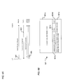
- FIG. 5A is a message flow diagram of a conventional two-phase access scheme for uplink data transmission
- FIG. 5B is diagram of the format of a conventional 8 and 11 bit packet channel request message
- FIG. 6A is a message flow diagram of a single-phase access scheme for uplink data transmission, according to an embodiment of the present invention.
- FIG. 6B is a diagram of the format of a 64-bit packet channel request message that combines elements of the packet resource request message, according to an embodiment of the present invention
- FIGS. 7A and 7B are diagrams of the forward and reverse MAC/RLC header formats, respectively, that support the piggybacking operation, in accordance with an embodiment of the present invention
- FIG. 8 is a flow chart of the process of employing the single-phase access scheme in conjunction with the two-phase access scheme, according to an embodiment of the present invention.
- FIG. 9 is a message flow diagram of the piggybacking operation and unsolicited grant mechanism, in accordance with an embodiment of the present invention.
- FIG. 10 is a diagram of a computer system that can execute the MAC/RLC layer protocol, in accordance with an embodiment of the present invention.
- the present invention optimizes protocol performance and user experience by minimizing response time associated with a radio communication system.
- a user terminal transmits a packet channel request message that specifies user terminal information using a contention channel according to a MAC/RLC protocol.
- a gateway station receives the packet channel request message and transmits an assignment message that specifies a channel assignment based upon the user terminal information.
- the terminal transmits the packets over a channel is based on the channel assignment.
- the radio communication system utilizes an unsolicited grant mechanism to streamline the exchange of control messages at the transport protocol level (e.g., TCP acknowledgements). Further efficiencies are gained by piggypacking control and data information as well as enabling the pipelining of multiple packet channel request messages and packet resource request messages.
- FIG. 1 is a diagram of a satellite communication system utilizing a Medium Access Control (MAC) and Radio Link Control (RLC) layer protocol, according to an embodiment of the present invention.
- a satellite communication system 100 includes a gateway station (GS) 101 that communicates with user terminals (UTs) 103 and 105 (through satellite 107 .
- feeder link 109 between the gateway station and the satellite is at C-band (4-8 GHz) and link 111 between the user terminal and the satellite is at L-band (1-2 GHz).
- a convention is adopted whereby the communication path 113 from gateway station 101 to the satellite 107 down to an UT, which in this example is UUT 103 , is denoted as the downlink or forward link.
- a communication path 115 from UT 105 up to the satellite 107 and down to the gateway station 101 is referred to as the uplink or return link.
- the satellite communication system 100 may support connectivity to a packet data network (PDN) to permit the UTs 103 and 105 to communicate with various terrestrial systems via the gateway station 101 .
- PDN packet data network
- the UTs 103 and 105 provide the subscriber interface to the system 100 .
- the user terminal types may include hand held, vehicular, aeronautical, maritime and stationary units.
- the gateway station 101 manages and allocates system communication resources that are necessary to support the communication traffic within their respective service areas, such as L-band spectrum and downlink EIRP (Effective Isotropically Radiated Power). For example, the gateway station 101 can provide allocation of communication resources within its service area (frequency and power), user authentication, and support of user roaming within the system coverage area.
- system communication resources that are necessary to support the communication traffic within their respective service areas, such as L-band spectrum and downlink EIRP (Effective Isotropically Radiated Power).
- the gateway station 101 can provide allocation of communication resources within its service area (frequency and power), user authentication, and support of user roaming within the system coverage area.
- FIG. 2 is a block diagram of a transmission plane for packet switched services in the system of FIG. 1.
- a UT e.g., 103
- the protocol stack has a Logical Link Control (LLC) layer 205 , above which is a Subnetwork Dependent Convergence Protocol (SNDCP) layer 207 .
- the protocol stack also includes an IP layer 209 that is below application layer 211 .
- the UT 103 communicates with a gateway station 101 via the RLC/MAC layer 201 and the physical layer 203 .
- the gateway station 101 communicates with a serving GPRS support node (SGSN) using the following functions: BSSGP 213 , network service 215 , and L 1 bis 217 .
- BSSGP layer 213 conveys routing and QoS (quality of service) related information between gateway station 101 and SGSN.
- Network Service layer 215 transports BSSGP protocol data units between gateway station 101 and SGSN, using technologies such as frame relay, for example.
- L 1 -bis 217 is the physical link between gateway station 101 and SGSN and is specified, for instance, in the International Telecommunications Union (ITU)-T G.703 standard, which is incorporated herein by reference.
- ITU International Telecommunications Union
- the SGSN that is on the side of the gateway station 101 includes the LLC layer 205 and the SNDCP layer 207 .
- the SGSN utilizes the following layers: L 1 layer 219 , L 2 layer 227 , an IP layer 223 , a UDP (User Datagram Protocol)/TCP (Transmission Control Protocol) layer 225 , and a GTP layer 227 .
- GGSN employs an IP/X.25 layer 209 to support peer-to-peer communication with the UT 103 .
- the MAC layer 201 a and RLC layer 201 b are modified from the conventional GSM standard to cater to longer delays associated with the satellite system 100 and to the different physical layer beneath these layers 201 a and 201 b.
- the MAC/RLC services of system 100 provides a marked improvement over the conventional GSM GPRS standard.
- the MAC layer 201 a defines the procedures that enable multiple UTs to share a common transmission medium, which may consist of several channels multiplexed over the same physical resource.
- the MAC layer 201 a provides arbitration between multiple UTs that are attempting to transmit simultaneously and provides collision avoidance, detection and recovery procedures.
- the operations of the MAC layer 201 a may allow a single UT to use several physical channels in parallel.
- the MAC layer 201 a is responsible for providing efficient multiplexing of data and control signaling on both uplink and downlink, in which the control resides on the Network side.
- multiplexing is controlled by a scheduling mechanism.
- multiplexing is controlled by medium allocation to individual users (e.g., in response to packet channel request).
- the MAC layer 201 a also provides contention resolution between packet channel request attempts, including collision detection and recovery, for UT originated channel access. Priority handling is also handled by the MAC layer 201 a.
- the RLC layer 201 b supports interface primitives that allows the transfer of Logical Link Control layer PDUs (LLC-PDU) between the LLC layer 205 and the MAC layer 201 a .
- the RLC layer is responsible for segmentation of LLC-PDUs into RLC Data Blocks and re-assembly of RLC Data Blocks to LLC-PDU.
- the RLC/MAC layer 201 function provides two modes of operation: unacknowledged operation, and acknowledged operation. In acknowledged mode of operation, the RLC/MAC supplies ARQ (automatic repeat request) procedures to enable the selective retransmission of missing or unrecoverable code blocks. It should be noted that to assist ARQ type of error recovery, the Block Check Sequence for error detection is provided by the Physical Link Layer 203 .
- FIG. 3 is a diagram of the mapping of network-packet data units, which may be IP. Packets at the network layer that is above the MAC/RLC layer, according to an embodiment of the present invention.
- the physical channel defined for GPRS is the Packet Data Channel (PDCH). Packet traffic and control channels are carried on the same physical channel.
- the packet data traffic channel (PDTCH), the packet associated control channel (PACCH) and packet common control channel (PCCCH) channels are multiplexed on the PDCH.
- Each Packet Data Channel PDCH is a shared medium between multiple UTs and the network.
- the radio interface includes asymmetric and independent uplink and downlink PDCH.
- the downlink carries transmissions from the network to multiple UTs and does not require contention arbitration.
- the uplink is shared among multiple UTs and requires contention control procedures.
- the allocated uplink and downlink radio resources may be used independently of each other. Depending on the terminal capabilities, the number of data blocks in the queue, and the resource availability, a UT may be assigned to one or a multiple of PDCHs.
- the system 100 may allocate radio resources for the uplink and downlink in a symmetric manner if so requested by the UT in Packet channel Request Message.
- the access to the uplink uses a Slotted-Aloha based reservation protocol.
- the Network Protocol Data Units (N-PDU) 301 such as IP packets, are segmented into the Subnetwork Protocol Data Units (SN-PDU) by the Subnetwork Dependent Convergence (SNDC) protocol 303 and SN-PDUs are encapsulated into LLC frames.
- the LLC 305 and SNDC 303 functionality are similar to that used in GSM GPRS as defined in GSM 04.64 and GSM 04.65, respectively; which are incorporated herein by reference in their entirety.
- FIG. 4 is a diagram of segmentation at the user terminal for uplink transmission, according to an embodiment of the present invention.
- LLC frames 401 are segmented into RLC Data Blocks 403 .
- the LLC frame 401 includes a frame header 401 a , an information field 401 b , and a frame check sequence (FCS) 401 c .
- Each RLC block 403 contains the following three fields: block header (BH) 403 a , an information field 403 b , and a block check sequence (BCS) 403 c .
- BH block header
- BCS block check sequence
- an uplink state flag (USF) is used to allow multiplexing of radio blocks from a number of UTs.
- USF is used in dynamic and extended dynamic medium access modes, as defined in GSM GPRS.
- a reserved USF pattern is used to permit users to determine the availability of a given uplink packet data channel for transmitting a packet channel request message. This is particularly necessary when packet common control channels PCCCH share a packet data channel with packet traffic data channel PDTCH (Packet Data Traffic Channel).
- PCCCH Packet Data Traffic Channel
- a Temporary Block Flow is a physical connection used by the two RR entities to support the unidirectional transfer of LLC PDUs on packet data physical channels.
- the TBF is allocated radio resource on one or more PDTCHs and comprise a number of RLC/MAC blocks carrying one or more LLC PDUs. As the name implies, TBF is temporary and is maintained only for the duration of the data transfer.
- Each TBF is assigned a Temporary Flow Identity (TFI) by the network.
- TFI Temporary Flow Identity
- the assigned TFI is unique among concurrent TBFs in each direction and is used instead of the UT identity in the RLC/MAC layer.
- the same TFI value may be used concurrently for TBFs in opposite directions.
- the TFI is assigned in PACKET UPLINK ASSIGNMENT and PACKET DOWNLINK ASSIGNMENT messages that precede the transfer of LLC frames 401 belonging to one TBF to/from the UT.
- the same TFI is included in every RLC header belonging to a particular TBF as well as in the control messages associated to the LLC frame 401 transfer (e.g., acknowledgements) in order to uniquely address the peer RLC entities.
- GSM GPRS permits the establishment of only a single TBF for the uplink and a single TBF for the downlink of a UT at any time.
- the network may assign multiple uplink TBF's and multiple downlink TBF's with different properties, such as reliability priority or precedence simultaneously.
- the system 100 support a fixed mode of medium access.
- a UT e.g., 103 and 105
- the network determines (after taking into account the propagation delay) the time-slot, frequency and the frame numbers on which the requesting terminal is expected to transmit and this information is transmitted to the UT in Packet Uplink Assignment message.
- FIG. 5A is a message flow diagram of a two-phase access scheme for uplink data transmission, as is used with the conventional GSM GPRS protocol.
- a UT initiates a packet transfer by making a Packet Channel Request on a random access channel (RACH), step 501 .
- RACH random access channel
- a UT first transmits an 8 or 11-bit Channel request message on RACH or PRACH (as shown in FIG. 5B, if PRACH is available) channel to the network, simply indicating its intention to perform a packet transfer; no details about, for example, UT identification, capabilities of the terminal, and mode of operation, can be provided in the 8 bit message or the 11 bit message.
- the gateway station 101 transmits, as in step 503 , a Packet Uplink Assignment message on AGCH or PAGCH, which allocates a single block of uplink resources.
- the Packet Resource Request message as transmitted, on the single assigned block of uplink resources in a PACCH, by the UT in step 505 , carries the complete description of the requested resources for the uplink transfer, for example, TLLI, RLC and LLC mode of operation, number of bytes required to transfer, radio priority, peak throughput class, and etc.
- the UT can indicate the medium access method that the UT prefers to be used during the TBF.
- the network responds with another Packet Uplink Assignment to reserve resources for the uplink transfer of data (step 507 ), taking into account the UT's capabilities, radio priority, resource availability etc.
- the UT then transmits uplink data over the PDTCH, per step 509 .
- this is inefficient and results in slow responsiveness.
- TCP at the transport layer remains in slow-start phase for an even longer duration.
- the protocol predominantly uses a two-phase access procedure for uplink data transmission, as described above.
- the approach according to an embodiment of the present invention employs a predominately single-phase access procedure, as discussed below.
- the UT makes a retry after a random backoff time.
- the optimal persistence of the UTs is calculated at the network side.
- the actual persistence values depend on the following factors: priority of the packet to be transmitted, amount of traffic within higher priority classes, and the amount of traffic within the own priority class.
- a backoff algorithm can be used. Occasionally, more Packet Channel Requests can be received than can be served. To address this issue, a Packet Queuing Notification, for example, is transmitted to the sender of the Packet Channel Request.
- the notification includes information that the Packet Channel Request message is correctly received and Packet Uplink Assignment may be transmitted later.
- the Packet Queueing Notification causes the sender to cease transmission of channel requests, thus preventing overloading of the contention access channels.
- the Fixed allocation uses the Packet Uplink Assignment message to communicate a detailed fixed uplink resource allocation to the UT.
- the fixed allocation has a start frame, slot assignment, and the assigned blocks (actually number of TDMA frames) per timeslot.
- the UT waits for the start frame and then transmits radio blocks on those blocks indicated in the block assignment bitmap.
- the fixed allocation does not include the USF and the UT is free to transmit on the uplink without monitoring the downlink for the USF. If the current allocation is not sufficient, the UT may request additional resources in one of the assigned uplink blocks by pre-empting the transmission of one of its own data blocks.
- a unique TFI is allocated and is thereafter included in each RLC data and control block related to that Temporary Block Flow. Because each Radio Block includes an identifier (TFI), all received Radio blocks are correctly associated with a particular LLC frame 401 and a particular UT.
- TFI identifier
- the number of blocks a UT requests in the initial and subsequent allocation request messages account for the number of data and control blocks the UT intends to send.
- the UT does not request additional blocks for the retransmission of erroneous blocks.
- the network can repeat the allocation of radio resources by setting the parameter in the Packet Uplink Assignment or the Packet Uplink Ack/Nack (Acknowledgement/Negative acknowledgement) message.
- Contention resolution is an important part of RLC/MAC protocol operation, especially because one channel allocation can be used to transfer a number of LLC frames 401 . Contention resolution applies for both dynamic and fixed allocation medium access modes.
- the two-phase access is inherently immune for the possibility that two UTs can perceive the same channel allocation as their own.
- the second access phase the Packet Resource Request
- the TLLI identifies the user in the system (between UT and SGSN).
- the TLLI is derived from P-TMSI allocated by SGSN or manufactured at the UT using methods which are detailed in Section 14.3 of GSM 03.60, which is incorporated herein by reference.
- the same TLLI is included in the Packet Uplink Assignment/Packet Downlink Assignment, and thus, the probability of mistake is significantly reduced.
- Identification of the UT poses a challenge in the one-phase access scheme.
- the identification of transmitting UT on the RLC/MAC level is necessary not only for contention resolution but also to be able to establish RLC protocol entity for that Temporary Block Flow on the network side.
- the TLLI is necessary to be able to match simultaneous uplink and downlink packet transfers by taking into consideration multislot capability of that UT.
- the packet channel request message transmitted on the PRACH has been designed so that the TLLI is included in this message. This saves the requirement of doing a post-TBF establishment contention resolution procedure.
- the single-phase access when the satellite is in geostationary earth orbit, the single-phase access may always be employed. For example, if the packet switched protocol described by the present invention were applied to the ETSI Geo-Mobile Radio-1 (GMR-1) air interface protocol, then single-phase access could always be achieved. However, when the satellite is in low earth orbit or mid-earth orbit and as a consequence is moving rapidly relative to the surface of the earth, the synchronization of the terminal may be an issue.
- GMR-1 ETSI Geo-Mobile Radio-1
- the two-phased access scheme may be employed if the user terminal (UT) (e.g.,UT 103 ) is not synchronized with the gateway station 101 (i.e., unsynchronized state). Because satellite 107 and the UT 103 are continually moving in such a system, message synchronization is needed to properly exchange data.
- UT user terminal
- the gateway station 101 i.e., unsynchronized state.
- message synchronization is needed to properly exchange data.
- subsequent communication sessions can be established using a one-phase access scheme; such an access scheme can be employed so long as the UT 103 does not “fall out” of synchronization. That is, if communication is not maintained between the UT 103 and the gateway station 101 beyond a certain time period, the UT 103 and the gateway station 101 will lose synchronization. Within this time period, the UT 103 and the gateway station 101 is in a synchronized state. This time period depends on a number of factors, including propagation delay, and system latency.
- FIG. 5B shows the conventional format of the 8 bit and 11 bit packet channel request message for two-phase access.
- a five bit indicator 01000 indicates two-phase access request.
- the 8 bit packet channel request message 521 also includes a 3 bit Random Reference field 521 b .
- an 11 bit packet channel request message 523 includes a six bit indicator 110000 to indicate two-phase access request.
- the 11 bit packet channel request message 523 utilizes a 2 bit Priority field 523 b to specify the priority associated with the packet channel request message 523 .
- the 11 bit packet channel request message 523 employs Random Reference field 523 c that has a length of 3 bits as in the case of the 8 bit message.
- FIG. 6A is a message flow diagram of a single-phase access scheme for uplink data transmission, according to an embodiment of the present invention.
- a physical channel for PRACH burst structure for the system 100 is defined so as to support a 64-bit packet channel request message, as shown in FIG. 6B, (in GSM RACH and PRACH physical channels carry the same 8 or 11 bit Packet Channel Request message and have the same burst structure) that permits single-phase access to be used predominantly, and hence, improve the responsiveness of the system.
- the PRACH burst structure carries a 64-bit Packet channel Request message with all the details about UT capabilities, TLLI, Radio Priority, RLC and LLC modes, etc.
- PRACH bursts are such that there is a longer guard time than regular PDCH bursts to accommodate timing uncertainties. Accordingly, the burst for the PRACH within a TDMA time slot is smaller than the PDCH burst.
- the UT 103 immediately transmits a 64-bit packet channel request message, per step 601 .
- the Packet Channel Request is answered by the network with the Packet Uplink Assignment, reserving the resources on PDTCH(s) for uplink transfer of a number of Radio blocks. The reservation is done according to the information about the requested resources that is comprised in the Packet Channel Request.
- This Packet Channel Request contains more adequate information about the requested resources including details of the QoS guarantees required for the transfer and, consequently, uplink resources on one or several PDTCHs can be assigned by using the Packet Uplink Assignment message.
- the UT 103 sends data, as in step 605 , over the PDTCHs that were assigned.
- FIG. 7A shows the process of transmitting data over the uplink of the system of FIG. 1 .
- single-phase access scheme does exist in the conventional GSM GPRS on RACH or PRACH, but has several drawbacks.
- the 8 or 11 bit packet Channel Request message does not contain UT capabilities, only a single PDCH can be allocated even though the terminal may be capable of transmitting in multiple slots. Therefore subsequent data transmissions will be at a very low throughput.
- the packet Channel Request message for one-phase access only has a 2 bit random reference, contention resolution is much longer and perhaps even longer than the time taken for a two-phase access. Therefore the PRACH design of the present invention accommodates the UT capabilities, TLLI, RLC and LLC modes, radio priority etc, so as to improve throughput and responsiveness of the system.
- FIGS. 7A and 7B show diagrams of the forward and reverse MAC/RLC header formats, respectively, that support the piggybacking operation, in accordance with an embodiment of the present invention.
- a MAC/RLC header 701 for the forward direction includes the following fields: a Packet Type field 701 a , a Rept.
- Extended field 701 l indicates whether the length of the Last Part Size field 701 I is increased by the length of field 701 k .
- the 701 a field indicates whether the RLC block contains a data-only or control-only or control+data in its payload.
- Field 701 b is a method to solicit a report or a response (such as RLC acknowledgement) from the UT 103 .
- Field 701 c indicates the power control bits that are used to dictate the power level to be used for UT transmission.
- Field 701 d in conjunction with field 701 h is the equivalent of a Temporary Flow Identifier (TFI) of GSM GPRS; this identifies the terminal at the RLC layer when the UT 103 is in packet transfer mode.
- Field 701 e in conjunction with field 701 j is the sequence number used in most ARQ based retransmission protocols.
- Field 701 f indicates the number of unsolicited uplink blocks granted to the UT 103 .
- Field 701 g indicates the UT 103 that the gateway station 101 has finished transmitted all LLC PDUs and none are outstanding; in RLC acknowledged mode this will trigger an RLC acknowledgement in UT 103 .
- Field 701 i together with field 701 k indicates the beginning point of a new LLC frame within the RLC block.
- MAC/RLC header 703 has the following fields: a Packet Type field 703 a , a Stall Indication field 703 b , a Terminal Session Identifier field 703 c , a Sequence Number field 703 d , an R field 703 e , a CV field 703 f , a Session Identifier field 703 g , a LastPart Size field 703 h , a Sequence Number field 703 i , a Last Part Size field 703 j , and an Extended field 703 k .
- Field 703 a indicates the packet type such as data and control.
- Field 703 b indicates whether the RLC layer in the UT 103 has stalled because of not receiving acknowledgement from the network.
- Field 703 c in conjunction with field 703 g is equivalent to Temporary Flow Identifier (TFI) of GSM GPRS.
- Field 703 d in conjunction with 703 i denotes the sequence number.
- Field 703 e is the Retry bit that indicates whether the RLC control block is a repetition of the previous attempt.
- Field 703 f indicates the Countdown Value (CV) which indicates to the network whether this is the last RLC block or more is pending.
- Field 703 h in conjunction with field 703 j carry the same information as that carried by field 701 i in conjunction with field 701 k .
- Field 703 k denotes the extension bit to permit future expansions of the MAC header.
- FIG. 8 shows a flowchart of the single-phase access scheme, according to an embodiment of the present invention.
- a single-phase access scheme is used whenever the terminal (e.g., UT 103 ) is in partial or coarse sync with the network 100 , such that the transmitted burst from the terminal falls within the timing acquisition window of the demodulator of a PRACH channel.
- the terminal e.g., UT 103
- a two-phase access scheme is used initially; that is, until synchronization is established.
- gateway station 101 determines whether the UT 103 is synchronized with the network 100 .
- a synchronization timer is used to make this determination.
- a packet data channel (e.g., an uplink transmission channel) is established using a two-phase access scheme, per step 807 .
- the synchronization timer has not expired, indicating that the UT 103 is synchronized with the network 100 , then the one phase access scheme is utilized (per step 805 ).
- the UT 103 transmits the data, as in step 809 . If there are more data to transmit, as determined by step 811 , then steps 801 - 809 are repeated as appropriate. However, the process ends if the UT 103 has no more data to send.
- FIG. 9 is a message flow diagram, illustrating the piggybacking operation and unsolicited grant mechanism, in accordance with an embodiment of the present invention.
- RLC acknowledgements from user terminal 103 are explicitly solicited by the network 100 , which is detailed in the GSM 04.60 standard (Section 9) and incorporated herein by reference. Transmission of an RLC acknowledgement is requested by the network 100 when it has completed transmission of LLC frames 401 and/or when the RLC window size has expired. At this juncture, the network 100 allocates only sufficient uplink resources to the user terminal 103 for transmitting an RLC acknowledgement. However, if the user terminal 103 subsequently has to send an upper layer acknowledgement, such as at LLC layer and more importantly at TCP layer, then the UT 103 has to undergo the uplink access procedure described in FIG. 7 A.
- an upper layer acknowledgement such as at LLC layer and more importantly at TCP layer
- system 100 employs an unsolicited uplink grant mechanism, which allocates additional uplink resources to the user terminal 103 , so as to permit the upper layer acknowledgements to be transported without undergoing an uplink access procedure. That is, the access procedures of FIGS. 5A and 6A are bypassed.
- the system 100 estimates the requirement of the terminal 103 based on its usage pattern. This mechanism of unsolicited uplink grants significantly improves the throughput of the system 100 and permits the TCP layers to transition out of the slow-start phase quickly.
- the gateway station 101 communicates with the UT 103 , which in turn, exchanges information with a host computer, for example.
- step 901 the network 100 transmits data to the UT 103 .
- the UT 103 Upon receiving the data, the UT 103 forwards the information to the host in form of an application protocol data unit (PDU), per step 903 .
- PDU application protocol data unit
- the network 100 allocates resources for the acknowledgement (step 905 ).
- the application on the host issues an acknowledgement. Because the network 100 has already dedicated resources for the acknowledgement, the UT 103 need not obtain uplink resources, using the access procedures of FIGS. 5A and 6A. Accordingly, the UT 103 transmits the acknowledgement, as in step 907 .
- the packet data system 100 allows piggybacking control and data frames.
- the UT 103 transmits an acknowledgement, along with data that has been received by the host, to the network 100 .
- the conventional GSM GPRS does not allow piggybacking of data and control frames.
- the MAC headers are defined to accommodate this mixture data-control RLC block as shown in FIGS. 7A and 7B.
- the host transmits data to the UT 103 , which then transfers the data to the network 100 (step 913 ).
- the data transfer is optimized by using a combination of unsolicited grants for acknowledgement and piggybacking the acknowledgement with data.
- the system 100 of FIG. 1 permits a pipeline of cumulative packet channel requests or packet resource requests so that the network 100 may simply respond to the latest request and ignore other requests if they have not yet been honored. This approach also mitigates the effects of lost requests.
- the UT 103 assists the network 100 in making response allocation decisions by explicitly indicating in the uplink MAC header whether a particular uplink packet resource request was a cumulative or a stand-alone packet resource request. Absence of this feature (namely, responding to requests as though each request was a stand-alone request) would have significantly increased the delay in resource allocation, and increase the number of messages to be handled for the same number of uplink resources.
- FIG. 10 illustrates a computer system 1001 upon which an embodiment according to the present invention may be implemented execute the MAC/RLC layer protocol.
- Computer system 1001 includes a bus 1003 or other communication mechanism for communicating information, and a processor 1005 coupled with bus 1003 for processing the information.
- Computer system 1001 also includes a main memory 1007 , such as a random access memory (RAM) or other dynamic storage device, coupled to bus 1003 for storing information and instructions to be executed by processor 1005 .
- main memory 1007 may be used for storing temporary variables or other intermediate information during execution of instructions to be executed by processor 1005 .
- Computer system 1001 further includes a read only memory (ROM) 1009 or other static storage device coupled to bus 1003 for storing static information and instructions for processor 1005 .
- ROM read only memory
- a storage device 1011 such as a magnetic disk or optical disk, is provided and coupled to bus 1003 for storing information and instructions.
- Computer system 1001 may be coupled via bus 1003 to a display 1013 , such as a cathode ray tube (CRT), for displaying information to a computer user.
- a display 1013 such as a cathode ray tube (CRT)
- An input device 1015 is coupled to bus 1003 for communicating information and command selections to processor 1005 .
- cursor control 1017 is Another type of user input device, such as a mouse, a trackball, or cursor direction keys for communicating direction information and command selections to processor 1005 and for controlling cursor movement on display 1013 .
- the single-phase access procedure is provided by computer system 1001 in response to processor 1005 executing one or more sequences of one or more instructions contained in main memory 1007 .
- Such instructions may be read into main memory 1007 from another computer-readable medium, such as storage device 1011 .
- Execution of the sequences of instructions contained in main memory 1007 causes processor 1005 to perform the process steps described herein.
- processors in a multi-processing arrangement may also be employed to execute the sequences of instructions contained in main memory 1007 .
- hard-wired circuitry may be used in place of or in combination with software instructions. Thus, embodiments are not limited to any specific combination of hardware circuitry and software.
- Non-volatile media includes, for example, optical or magnetic disks, such as storage device 1011 .
- Volatile media includes dynamic memory, such as main memory 1007 .
- Transmission media includes coaxial cables, copper wire and fiber optics, including the wires that comprise bus 1003 . Transmission media can also take the form of acoustic or light waves, such as those generated during radio wave and infrared data communication.
- Computer-readable media include, for example, a floppy disk, a flexible disk, hard disk, magnetic tape, or any other magnetic medium, a CD-ROM, any other optical medium, punch cards, paper tape, any other physical medium with patterns of holes, a RAM, a PROM, and EPROM, a FLASH-EPROM, any other memory chip or cartridge, a carrier wave as described hereinafter, or any other medium from which a computer can read.
- Various forms of computer readable media may be involved in carrying one or more sequences of one or more instructions to processor 1005 for execution.
- the instructions may initially be carried on a magnetic disk of a remote computer.
- the remote computer can load the instructions relating to the notification services to control call processing remotely into its dynamic memory and send the instructions over a telephone line using a modem.
- a modem local to computer system 1001 can receive the data on the telephone line and use an infrared transmitter to convert the data to an infrared signal.
- An infrared detector coupled to bus 1003 can receive the data carried in the infrared signal and place the data on bus 1003 .
- Bus 1003 carries the data to main memory 1007 , from which processor 1005 retrieves and executes the instructions.
- the instructions received by main memory 1007 may optionally be stored on storage device 1011 either before or after execution by processor 1005 .
- Computer system 1001 also includes a communication interface 1019 coupled to bus 1003 .
- Communication interface 1019 provides a two-way data communication coupling to a network link 1021 that is connected to a local network 1023 .
- communication interface 1019 may be a network interface card to attach to any packet switched local area network (LAN).
- communication interface 1019 may be an asymmetrical digital subscriber line (ADSL) card, an integrated services digital network (ISDN) card or a modem to provide a data communication connection to a corresponding type of telephone line.
- ADSL asymmetrical digital subscriber line
- ISDN integrated services digital network
- Wireless links may also be implemented.
- communication interface 1019 sends and receives electrical, electromagnetic or optical signals that carry digital data streams representing various types of information.
- Network link 1021 typically provides data communication through one or more networks to other data devices.
- network link 1021 may provide a connection through local network 1023 to a host computer 1025 or to data equipment operated by a service provider, which provides data communication services through a communication network 1027 (e.g., the Internet).
- LAN 1023 and network 1027 both use electrical, electromagnetic or optical signals that carry digital data streams.
- the signals through the various networks and the signals on network link 1021 and through communication interface 1019 which carry the digital data to and from computer system 1001 , are exemplary forms of carrier waves transporting the information.
- Computer system 1001 can transmit notifications and receive data, including program code, through the network(s), network link 1021 and communication interface 1019 .
- the techniques described herein provide several advantages over prior approaches to providing increased system throughput and efficiency of a satellite communication system, thereby minimizing response time.
- the terminal When a user terminal is in a synchronized state, the terminal utilizes a single-phase access procedure according to a medium access control (MAC) protocol and radio link control (RLC) protocol to obtain a packet data channel.
- the gateway station receives the packet channel request message and transmits an assignment message that specifies a channel assignment based upon the user terminal information.
- the system utilizes an unsolicited grant mechanism to streamline the exchange of control messages (e.g., TCP acknowledgements). Further efficiencies are gained by piggypacking control and data information and pipelining the packet resource request messages.
Abstract
Description
Claims (8)
Priority Applications (1)
| Application Number | Priority Date | Filing Date | Title |
|---|---|---|---|
| US09/714,788 US6778509B1 (en) | 1999-11-19 | 2000-11-16 | MAC layer protocol for a satellite based packet switched services |
Applications Claiming Priority (3)
| Application Number | Priority Date | Filing Date | Title |
|---|---|---|---|
| US16647299P | 1999-11-19 | 1999-11-19 | |
| US18606000P | 2000-03-01 | 2000-03-01 | |
| US09/714,788 US6778509B1 (en) | 1999-11-19 | 2000-11-16 | MAC layer protocol for a satellite based packet switched services |
Publications (1)
| Publication Number | Publication Date |
|---|---|
| US6778509B1 true US6778509B1 (en) | 2004-08-17 |
Family
ID=32854206
Family Applications (1)
| Application Number | Title | Priority Date | Filing Date |
|---|---|---|---|
| US09/714,788 Expired - Lifetime US6778509B1 (en) | 1999-11-19 | 2000-11-16 | MAC layer protocol for a satellite based packet switched services |
Country Status (1)
| Country | Link |
|---|---|
| US (1) | US6778509B1 (en) |
Cited By (43)
| Publication number | Priority date | Publication date | Assignee | Title |
|---|---|---|---|---|
| US20010055312A1 (en) * | 2000-04-07 | 2001-12-27 | Negus Kevin J. | Asymmetric data traffic throughput in CSMA/CA networks |
| US20020141359A1 (en) * | 2001-04-03 | 2002-10-03 | Samsung Electronics Co., Ltd. | Packet data transmitting/receiving method in mobile communication system |
| US20020181422A1 (en) * | 2001-02-09 | 2002-12-05 | Janne Parantainen | Advanced method and arrangement for transferring information in a packet radio service |
| US20030046409A1 (en) * | 2001-08-30 | 2003-03-06 | Graham John C. | Metered internet usage |
| US20040047292A1 (en) * | 2000-04-25 | 2004-03-11 | Du Crest Gilles | Radio telecommunications system and method of operating the same with reduced delays for data transmission over a radio interface |
| US20040258037A1 (en) * | 2003-06-18 | 2004-12-23 | Matsushita Electric Industrial Co., Ltd. | Extended dynamic resource allocation in packet data transfer |
| US20050124291A1 (en) * | 2001-11-26 | 2005-06-09 | Hart Nicholas R. | Satellite system for vessel identification |
| US20060018318A1 (en) * | 2004-07-15 | 2006-01-26 | Nokia Corporation | In-band set-up and configuration of transfer-related resources |
| US20060251031A1 (en) * | 2005-05-03 | 2006-11-09 | Ipwireless, Inc. | Apparatus and method for communicating signaling information |
| US20060251030A1 (en) * | 2005-05-03 | 2006-11-09 | Ipwireless, Inc. | Apparatus and method for communicating uplink signaling information |
| US20070030834A1 (en) * | 2005-08-05 | 2007-02-08 | Rappaport Matthew B | Systems and methods for facilitating communications over a shared channel |
| US20070104136A1 (en) * | 2005-11-10 | 2007-05-10 | Mark Pecen | Apparatus and method for signaling communication resource allocation on a block basis |
| US20070195762A1 (en) * | 2006-02-23 | 2007-08-23 | Samsung Electronics Co., Ltd | Method of classifying data and transmitting data in a PLC network and apparatus therefor |
| WO2007120113A1 (en) * | 2006-04-19 | 2007-10-25 | Telefonaktiebolaget Lm Ericsson (Publ) | Method, communication entity and system for transmiting positive and negative acknowledgements in a radio communications system |
| US20080025210A1 (en) * | 2006-07-25 | 2008-01-31 | Hooman Honary | Method and system for medium access control (MAC) layer specialization for voice and multimedia data streams |
| US20080056303A1 (en) * | 2006-08-30 | 2008-03-06 | Nokia Corporation | Method and apparatus for fast or negative acknowledgement in a mobile communication system |
| WO2008060756A2 (en) | 2006-10-03 | 2008-05-22 | Viasat, Inc. | Web/bulk transfer preallocation of upstream resources in a satellite communication system |
| US20080146145A1 (en) * | 2006-12-14 | 2008-06-19 | Viasat, Inc. | Satellite communication system and method with asymmetric feeder and service frequency bands |
| US20080310389A1 (en) * | 2007-06-18 | 2008-12-18 | Takashi Suzuki | Method and System for Dynamic ACK/NACK Repetition for Robust Downlink MAC PDU Transmission in LTE |
| WO2008155688A1 (en) * | 2007-06-20 | 2008-12-24 | Koninklijke Philips Electronics N.V. | Method for allocating transmission resources in a telecommunication system, a primary station and a secondary station for carrying out the method. |
| US20090046641A1 (en) * | 2007-08-13 | 2009-02-19 | Interdigital Patent Holdings, Inc. | Long term evolution medium access control procedures |
| WO2009057044A1 (en) * | 2007-11-01 | 2009-05-07 | Koninklijke Philips Electronics N.V. | Indicating e-dch resources for e-rach |
| US20090141700A1 (en) * | 2005-10-21 | 2009-06-04 | Robert Baldemair | Technique for performing a random access procedure over a radio interface |
| US20090290532A1 (en) * | 2006-10-03 | 2009-11-26 | Viasat Inc. | Map-triggered dump of packets in satellite communication system |
| US20090290534A1 (en) * | 2006-10-03 | 2009-11-26 | Viasat, Inc. | Upfront delayed concatenation in satellite communication system |
| US20090290531A1 (en) * | 2006-10-03 | 2009-11-26 | Viasat Inc. | Large packet concatenation in satellite communication system |
| US20100037308A1 (en) * | 2006-10-03 | 2010-02-11 | Viasat, Inc. | Multi-service provider authentication |
| US20100117486A1 (en) * | 2005-04-29 | 2010-05-13 | University Of Northumbria At Newcastle | Positioning apparatus and method |
| US20100131816A1 (en) * | 2007-06-08 | 2010-05-27 | National University Corporation Nagoya University | Communication system adapting for car, communication apparatus adapting for car, and communication method adapting for car |
| CN101155383B (en) * | 2006-09-29 | 2010-07-21 | 华为技术有限公司 | Indication method for resource allocation information, transmission method and device for indication information |
| US20100269006A1 (en) * | 2009-04-17 | 2010-10-21 | Samsung Electronics Co. Ltd. | Apparatus and method for transmitting and receiving automatic repeat request feedback message in wireless communication system |
| WO2010133754A1 (en) | 2009-05-18 | 2010-11-25 | Nokia Corporation | Systems, methods, and apparatuses for facilitating allocation of a common resource to a terminal |
| US20110111693A1 (en) * | 2008-02-14 | 2011-05-12 | Seigo Nakao | Radio communication base station device, radio communication relay station device, radio communication terminal device, radio communication system, and radio communication method |
| US20110170488A1 (en) * | 2007-05-08 | 2011-07-14 | Interdigital Technology Corporation | Method and apparatus for providing piggybacked positive acknowledgement/negative acknowledgement field indicator and a polling indicator |
| CN102256372A (en) * | 2010-05-17 | 2011-11-23 | 中兴通讯股份有限公司 | MTC terminal access method, system thereof and MTC terminal |
| US20120230268A1 (en) * | 2011-03-07 | 2012-09-13 | Interdigital Patent Holdings, Inc. | Method and apparatus for sending uplink control information for multi-radio access technology operation |
| US20130283109A1 (en) * | 2009-03-31 | 2013-10-24 | Infineon Technologies Ag | Network Retransmission Protocols Using a Proxy Node |
| US20140038622A1 (en) * | 2012-05-22 | 2014-02-06 | Qualcomm Incorporated | Methods and apparatus for efficient communication of small data amounts while in idle mode |
| WO2015050480A1 (en) * | 2013-10-01 | 2015-04-09 | Telefonaktiebolaget L M Ericsson (Publ) | A network node, a base station for uplink grant pre-allocation |
| US20150188985A1 (en) * | 2012-08-16 | 2015-07-02 | Airbus Defence And Space Sas | Device and method for unidirectional data transfer |
| US20170170914A1 (en) * | 2015-12-14 | 2017-06-15 | Hughes Systique Private Limited | Method and system for scheduling and mitigating cross-cell interference |
| USRE46679E1 (en) | 2005-10-31 | 2018-01-16 | Evolved Wireless Llc | Method of transmitting and receiving radio access information in a wireless mobile communications system |
| US20180132253A1 (en) * | 2015-07-10 | 2018-05-10 | Huawei Technologies Co., Ltd. | Channel access period allocation method, apparatus, and system |
Citations (10)
| Publication number | Priority date | Publication date | Assignee | Title |
|---|---|---|---|---|
| US5615215A (en) * | 1994-06-08 | 1997-03-25 | Alcatel N.V. | Extended range TDMA system |
| US5717830A (en) * | 1995-09-19 | 1998-02-10 | Amsc Subsidiary Corporation | Satellite trunked radio service system |
| US5896376A (en) * | 1996-12-13 | 1999-04-20 | Ericsson Inc. | Optimal use of logical channels within a mobile telecommunications network |
| US5946618A (en) * | 1996-11-04 | 1999-08-31 | Qualcomm Incorporated | Method and apparatus for performing position-based call processing in a mobile telephone system using multiple location mapping schemes |
| US6094429A (en) * | 1998-03-02 | 2000-07-25 | Motorola, Inc. | Method for accessing and providing access to a packet channel |
| US6157621A (en) * | 1991-10-28 | 2000-12-05 | Teledesic Llc | Satellite communication system |
| US6438386B2 (en) * | 1997-07-14 | 2002-08-20 | Hughes Electronics Corporation | Immediate channel assignment in a wireless system |
| US6469992B1 (en) * | 1997-10-22 | 2002-10-22 | Telefonaktiebolaget Lm Ericsson (Publ) | Intelligent packet retransmission scheme |
| US6532225B1 (en) * | 1999-07-27 | 2003-03-11 | At&T Corp | Medium access control layer for packetized wireless systems |
| US6560215B1 (en) * | 1999-08-24 | 2003-05-06 | Motorola, Inc. | Method and apparatus for updating a timing offset in a communication device |
-
2000
- 2000-11-16 US US09/714,788 patent/US6778509B1/en not_active Expired - Lifetime
Patent Citations (10)
| Publication number | Priority date | Publication date | Assignee | Title |
|---|---|---|---|---|
| US6157621A (en) * | 1991-10-28 | 2000-12-05 | Teledesic Llc | Satellite communication system |
| US5615215A (en) * | 1994-06-08 | 1997-03-25 | Alcatel N.V. | Extended range TDMA system |
| US5717830A (en) * | 1995-09-19 | 1998-02-10 | Amsc Subsidiary Corporation | Satellite trunked radio service system |
| US5946618A (en) * | 1996-11-04 | 1999-08-31 | Qualcomm Incorporated | Method and apparatus for performing position-based call processing in a mobile telephone system using multiple location mapping schemes |
| US5896376A (en) * | 1996-12-13 | 1999-04-20 | Ericsson Inc. | Optimal use of logical channels within a mobile telecommunications network |
| US6438386B2 (en) * | 1997-07-14 | 2002-08-20 | Hughes Electronics Corporation | Immediate channel assignment in a wireless system |
| US6469992B1 (en) * | 1997-10-22 | 2002-10-22 | Telefonaktiebolaget Lm Ericsson (Publ) | Intelligent packet retransmission scheme |
| US6094429A (en) * | 1998-03-02 | 2000-07-25 | Motorola, Inc. | Method for accessing and providing access to a packet channel |
| US6532225B1 (en) * | 1999-07-27 | 2003-03-11 | At&T Corp | Medium access control layer for packetized wireless systems |
| US6560215B1 (en) * | 1999-08-24 | 2003-05-06 | Motorola, Inc. | Method and apparatus for updating a timing offset in a communication device |
Cited By (137)
| Publication number | Priority date | Publication date | Assignee | Title |
|---|---|---|---|---|
| US20010055312A1 (en) * | 2000-04-07 | 2001-12-27 | Negus Kevin J. | Asymmetric data traffic throughput in CSMA/CA networks |
| US7035283B2 (en) * | 2000-04-07 | 2006-04-25 | Negus Kevin J | Asymmetric data traffic throughput in CSMA/CA networks |
| US20040047292A1 (en) * | 2000-04-25 | 2004-03-11 | Du Crest Gilles | Radio telecommunications system and method of operating the same with reduced delays for data transmission over a radio interface |
| US7551580B2 (en) * | 2000-04-25 | 2009-06-23 | Nortel Networks Limited | Radio telecommunications system and method of operating the same with reduced delays for data transmission over a radio interface |
| US7092373B2 (en) * | 2001-02-09 | 2006-08-15 | Nokia Corporation | Advanced method and arrangement for transferring information in a packet radio service |
| US20020181422A1 (en) * | 2001-02-09 | 2002-12-05 | Janne Parantainen | Advanced method and arrangement for transferring information in a packet radio service |
| US20020141359A1 (en) * | 2001-04-03 | 2002-10-03 | Samsung Electronics Co., Ltd. | Packet data transmitting/receiving method in mobile communication system |
| US7158495B2 (en) * | 2001-04-03 | 2007-01-02 | Samsung Electronics Co., Ltd. | Packet data transmitting/receiving method in mobile communication system |
| US20030046409A1 (en) * | 2001-08-30 | 2003-03-06 | Graham John C. | Metered internet usage |
| US7089304B2 (en) * | 2001-08-30 | 2006-08-08 | Microsoft Corporation | Metered Internet usage |
| US7483672B2 (en) * | 2001-11-26 | 2009-01-27 | Thiss Technologies Pte Ltd | Satellite system for vessel identification |
| US20050124291A1 (en) * | 2001-11-26 | 2005-06-09 | Hart Nicholas R. | Satellite system for vessel identification |
| US20040258037A1 (en) * | 2003-06-18 | 2004-12-23 | Matsushita Electric Industrial Co., Ltd. | Extended dynamic resource allocation in packet data transfer |
| US7835745B2 (en) * | 2004-07-15 | 2010-11-16 | Nokia Corporation | In-band set-up and configuration of transfer-related resources |
| US20060018318A1 (en) * | 2004-07-15 | 2006-01-26 | Nokia Corporation | In-band set-up and configuration of transfer-related resources |
| US8179019B2 (en) | 2005-04-29 | 2012-05-15 | Nanomobile Ltd. | Positioning apparatus and method |
| US20100117486A1 (en) * | 2005-04-29 | 2010-05-13 | University Of Northumbria At Newcastle | Positioning apparatus and method |
| EP2254384A3 (en) * | 2005-05-03 | 2010-12-29 | Sony Corporation | Signalling scheduling assitance data in a cellular communication system |
| EP2330859A1 (en) * | 2005-05-03 | 2011-06-08 | Sony Corporation | Signaling scheduling assistance data in a cellular communication system |
| US20060251031A1 (en) * | 2005-05-03 | 2006-11-09 | Ipwireless, Inc. | Apparatus and method for communicating signaling information |
| US8149778B2 (en) | 2005-05-03 | 2012-04-03 | Sony Corporation | Apparatus and method for communicating uplink signaling information |
| EP2254383A3 (en) * | 2005-05-03 | 2012-03-21 | Sony Corporation | Signalling scheduling assitance data in a cellular communication system |
| US20060251030A1 (en) * | 2005-05-03 | 2006-11-09 | Ipwireless, Inc. | Apparatus and method for communicating uplink signaling information |
| US8472395B2 (en) | 2005-05-03 | 2013-06-25 | Sony Corporation | Apparatus and method for communicating uplink signaling information |
| EP2375845A1 (en) * | 2005-05-03 | 2011-10-12 | Sony Corporation | Signaling scheduling assistance data in a cellular communication system |
| EP1942696A1 (en) | 2005-05-03 | 2008-07-09 | IPWireless, Inc. | Signalling scheduling assitance data in a cellular communication system |
| EP2375846A1 (en) * | 2005-05-03 | 2011-10-12 | Sony Corporation | Signaling scheduling assistance data in a cellular communication system |
| EP2357871A1 (en) * | 2005-05-03 | 2011-08-17 | Sony Corporation | Signaling scheduling assistance data in a cellular communication system |
| CN103354665A (en) * | 2005-05-03 | 2013-10-16 | 索尼公司 | Apparatus and method for communicating signalling information |
| US8570968B2 (en) | 2005-05-03 | 2013-10-29 | Sony Corporation | Apparatus and method for communicating uplink signaling information |
| CN103401646A (en) * | 2005-05-03 | 2013-11-20 | 索尼公司 | Device and method for communicating signalling information |
| EP2254385A3 (en) * | 2005-05-03 | 2010-12-29 | Sony Corporation | Signalling scheduling assistance data in a cellular communication system |
| CN101252414B (en) * | 2005-05-03 | 2012-07-11 | 索尼公司 | Apparatus and method for communicating signalling information |
| EP2244520A3 (en) * | 2005-05-03 | 2010-12-29 | Sony Corporation | Signalling scheduling assistance data in a cellular communication system |
| KR101340224B1 (en) * | 2005-05-03 | 2013-12-10 | 소니 주식회사 | Apparatus and method for communicating signalling information |
| US9674864B2 (en) | 2005-05-03 | 2017-06-06 | Sony Corporation | Apparatus and method for communicating uplink signaling information |
| US7616603B2 (en) | 2005-05-03 | 2009-11-10 | Nicholas William Anderson | Apparatus and method for communicating signaling information |
| CN103401646B (en) * | 2005-05-03 | 2016-12-07 | 索尼公司 | For transmitting equipment and the method for signaling information |
| CN103354665B (en) * | 2005-05-03 | 2016-12-07 | 索尼公司 | For transmitting equipment and the method for signaling information |
| US9307552B2 (en) | 2005-05-03 | 2016-04-05 | Sony Corporation | Apparatus and method for communicating uplink signaling information |
| EP2999290A1 (en) * | 2005-05-03 | 2016-03-23 | Sony Corporation | Signaling scheduling assistance data in a cellular communication system |
| US7701901B2 (en) | 2005-05-03 | 2010-04-20 | Ipwireless, Inc. | Apparatus and method for communicating uplink signaling information |
| WO2006117252A1 (en) * | 2005-05-03 | 2006-11-09 | Ipwireless Inc | Signalling scheduling assitance data in a cellular communication system |
| KR101340100B1 (en) * | 2005-05-03 | 2013-12-10 | 소니 주식회사 | Apparatus and method for communicating signalling information |
| CN101194532B (en) * | 2005-05-03 | 2014-01-01 | 索尼公司 | Device and method for transmitting signalling |
| US20100195544A1 (en) * | 2005-05-03 | 2010-08-05 | Ipwireless, Inc. | Apparatus and Method for Communicating Uplink Signaling Information |
| US8929320B2 (en) | 2005-05-03 | 2015-01-06 | Sony Corporation | Apparatus and method for communicating uplink signaling information |
| US7835760B2 (en) | 2005-08-05 | 2010-11-16 | Mobile Satellite Ventures, Lp | Systems and methods for facilitating communications over a shared channel |
| US8385924B2 (en) | 2005-08-05 | 2013-02-26 | Atc Technologies | Systems and methods for facilitating communications over a shared channel |
| US20110026404A1 (en) * | 2005-08-05 | 2011-02-03 | Mobile Satellite Ventures, Lp | Systems and methods for facilitating communications over a shared channel |
| US20070030834A1 (en) * | 2005-08-05 | 2007-02-08 | Rappaport Matthew B | Systems and methods for facilitating communications over a shared channel |
| US8503426B2 (en) * | 2005-10-21 | 2013-08-06 | Telefonaktiebolaget L M Ericsson (Publ) | Technique for performing a random access procedure over a radio interface |
| US10492226B2 (en) * | 2005-10-21 | 2019-11-26 | Telefonaktiebolaget Lm Ericsson (Publ) | Technique for performing a random access procedure over a radio interface |
| US20090141700A1 (en) * | 2005-10-21 | 2009-06-04 | Robert Baldemair | Technique for performing a random access procedure over a radio interface |
| US11770858B2 (en) | 2005-10-21 | 2023-09-26 | Telefonaktiebolaget Lm Ericsson (Publ) | Technique for performing a random access procedure over a radio interface |
| US11246167B2 (en) | 2005-10-21 | 2022-02-08 | Telefonaktiebolaget Lm Ericsson (Publ) | Technique for performing a random access procedure over a radio interface |
| US20130308615A1 (en) * | 2005-10-21 | 2013-11-21 | Telefonaktiebolaget L M Ericsson (Publ) | Technique for performing a random access procedure over a radio interface |
| US10219302B2 (en) * | 2005-10-21 | 2019-02-26 | Telefonaktiebolaget Lm Ericsson (Publ) | Technique for performing a random access procedure over a radio interface |
| US20150189678A1 (en) * | 2005-10-21 | 2015-07-02 | Telefonaktiebolaget L M Ericsson (Publ) | Technique for Performing a Random Access Procedure over a Radio Interface |
| USRE48326E1 (en) | 2005-10-31 | 2020-11-24 | Evolved Wireless Llc | Method of transmitting and receiving radio access information in a wireless mobile communications system |
| USRE46679E1 (en) | 2005-10-31 | 2018-01-16 | Evolved Wireless Llc | Method of transmitting and receiving radio access information in a wireless mobile communications system |
| USRE46714E1 (en) * | 2005-10-31 | 2018-02-13 | Evolved Wireless Llc | Method of transmitting and receiving radio access information in a wireless mobile communications system |
| USRE48478E1 (en) | 2005-10-31 | 2021-03-16 | Evolved Wireless Llc | Method of transmitting and receiving radio access information in a wireless mobile communications system |
| US20070104136A1 (en) * | 2005-11-10 | 2007-05-10 | Mark Pecen | Apparatus and method for signaling communication resource allocation on a block basis |
| US7773996B2 (en) * | 2005-11-10 | 2010-08-10 | Research In Motion Limited | Apparatus and method for signaling communication resource allocation on a block basis |
| US20070195762A1 (en) * | 2006-02-23 | 2007-08-23 | Samsung Electronics Co., Ltd | Method of classifying data and transmitting data in a PLC network and apparatus therefor |
| US8320243B2 (en) * | 2006-02-23 | 2012-11-27 | Samsung Electronics Co., Ltd. | Method of classifying data and transmitting data in a PLC network and apparatus therefor |
| WO2007120113A1 (en) * | 2006-04-19 | 2007-10-25 | Telefonaktiebolaget Lm Ericsson (Publ) | Method, communication entity and system for transmiting positive and negative acknowledgements in a radio communications system |
| US8411581B2 (en) * | 2006-07-25 | 2013-04-02 | Broadcom Corporation | Method and system for medium access control (MAC) layer specialization for voice and multimedia data streams |
| US20080025210A1 (en) * | 2006-07-25 | 2008-01-31 | Hooman Honary | Method and system for medium access control (MAC) layer specialization for voice and multimedia data streams |
| WO2008029210A3 (en) * | 2006-08-30 | 2008-05-15 | Nokia Corp | Method and apparatus for fast or negative acknowledgement in a mobile communication system |
| WO2008029210A2 (en) * | 2006-08-30 | 2008-03-13 | Nokia Corporation | Method and apparatus for fast or negative acknowledgement in a mobile communication system |
| US20080056303A1 (en) * | 2006-08-30 | 2008-03-06 | Nokia Corporation | Method and apparatus for fast or negative acknowledgement in a mobile communication system |
| CN101155383B (en) * | 2006-09-29 | 2010-07-21 | 华为技术有限公司 | Indication method for resource allocation information, transmission method and device for indication information |
| US8107368B2 (en) | 2006-10-03 | 2012-01-31 | Viasat, Inc. | Large packet concatenation in satellite communication system |
| US20090290532A1 (en) * | 2006-10-03 | 2009-11-26 | Viasat Inc. | Map-triggered dump of packets in satellite communication system |
| US8218473B2 (en) | 2006-10-03 | 2012-07-10 | Viasat, Inc. | Web-bulk transfer preallocation of upstream resources in a satellite communication system |
| US20100037308A1 (en) * | 2006-10-03 | 2010-02-11 | Viasat, Inc. | Multi-service provider authentication |
| US8107410B2 (en) | 2006-10-03 | 2012-01-31 | Viasat, Inc. | Map-triggered dump of packets in satellite communication system |
| US20090290534A1 (en) * | 2006-10-03 | 2009-11-26 | Viasat, Inc. | Upfront delayed concatenation in satellite communication system |
| WO2008060756A2 (en) | 2006-10-03 | 2008-05-22 | Viasat, Inc. | Web/bulk transfer preallocation of upstream resources in a satellite communication system |
| WO2008060756A3 (en) * | 2006-10-03 | 2008-07-17 | Viasat Inc | Web/bulk transfer preallocation of upstream resources in a satellite communication system |
| US20090290531A1 (en) * | 2006-10-03 | 2009-11-26 | Viasat Inc. | Large packet concatenation in satellite communication system |
| US20080146145A1 (en) * | 2006-12-14 | 2008-06-19 | Viasat, Inc. | Satellite communication system and method with asymmetric feeder and service frequency bands |
| US7869759B2 (en) | 2006-12-14 | 2011-01-11 | Viasat, Inc. | Satellite communication system and method with asymmetric feeder and service frequency bands |
| US20110170488A1 (en) * | 2007-05-08 | 2011-07-14 | Interdigital Technology Corporation | Method and apparatus for providing piggybacked positive acknowledgement/negative acknowledgement field indicator and a polling indicator |
| TWI451718B (en) * | 2007-05-08 | 2014-09-01 | Interdigital Tech Corp | Method and apparatus for providing piggybacked positive acknowledgement/negative acknowledgement field indicator and a polling indicator |
| US20100131816A1 (en) * | 2007-06-08 | 2010-05-27 | National University Corporation Nagoya University | Communication system adapting for car, communication apparatus adapting for car, and communication method adapting for car |
| US8448035B2 (en) * | 2007-06-08 | 2013-05-21 | National University Corporation Nagoya University | Communication system adapting for car, communication apparatus adapting for car, and communication method adapting for car |
| US11722282B2 (en) | 2007-06-18 | 2023-08-08 | Blackberry Limited | Method and system for dynamic ACK/NACK repetition for robust downlink MAC PDU transmission in LTE |
| US10020925B2 (en) | 2007-06-18 | 2018-07-10 | Blackberry Limited | Method and system for dynamic ACK/NACK repetition for robust downlink MAC PDU transmission in LTE |
| US8665796B2 (en) | 2007-06-18 | 2014-03-04 | Blackberry Limited | Method and system for dynamic ACK/NACK repetition for robust downlink MAC PDU transmission in LTE |
| US20080310389A1 (en) * | 2007-06-18 | 2008-12-18 | Takashi Suzuki | Method and System for Dynamic ACK/NACK Repetition for Robust Downlink MAC PDU Transmission in LTE |
| US11283577B2 (en) | 2007-06-18 | 2022-03-22 | Blackberry Limited | Method and system for dynamic ACK/NACK repetition for robust downlink MAC PDU transmission in LTE |
| US8976737B2 (en) | 2007-06-18 | 2015-03-10 | Blackberry Limited | Method and system for dynamic ACK/NACK repetition for robust downlink MAC PDU transmission in LTE |
| US8204010B2 (en) * | 2007-06-18 | 2012-06-19 | Research In Motion Limited | Method and system for dynamic ACK/NACK repetition for robust downlink MAC PDU transmission in LTE |
| WO2008155688A1 (en) * | 2007-06-20 | 2008-12-24 | Koninklijke Philips Electronics N.V. | Method for allocating transmission resources in a telecommunication system, a primary station and a secondary station for carrying out the method. |
| WO2009023470A2 (en) * | 2007-08-13 | 2009-02-19 | Interdigital Patent Holdings, Inc. | Long term evolution medium access control procedures |
| WO2009023470A3 (en) * | 2007-08-13 | 2009-10-22 | Interdigital Patent Holdings, Inc. | Long term evolution medium access control procedures |
| US20090046641A1 (en) * | 2007-08-13 | 2009-02-19 | Interdigital Patent Holdings, Inc. | Long term evolution medium access control procedures |
| CN101843161A (en) * | 2007-11-01 | 2010-09-22 | 皇家飞利浦电子股份有限公司 | Indicating e-dch resources for e-rach |
| US9392620B2 (en) | 2007-11-01 | 2016-07-12 | Koninklijke Philips N.V. | Indicating E-DCH resources for E-RACH |
| CN101843161B (en) * | 2007-11-01 | 2013-12-18 | 皇家飞利浦电子股份有限公司 | Indicating E-DCH resources for E-RACH |
| TWI484851B (en) * | 2007-11-01 | 2015-05-11 | Koninkl Philips Electronics Nv | Indicating e-dch resources for e-rach |
| WO2009057044A1 (en) * | 2007-11-01 | 2009-05-07 | Koninklijke Philips Electronics N.V. | Indicating e-dch resources for e-rach |
| JP2011503952A (en) * | 2007-11-01 | 2011-01-27 | コーニンクレッカ フィリップス エレクトロニクス エヌ ヴィ | Indication of E-DCH resource for E-RACH |
| RU2518176C2 (en) * | 2007-11-01 | 2014-06-10 | Конинклейке Филипс Электроникс Н.В. | Indicating e-dch resources for e-rach |
| US9497777B2 (en) | 2007-11-01 | 2016-11-15 | Koninklijke Philips N.V. | Indicating E-DCH resources for E-RACH |
| US20100203915A1 (en) * | 2007-11-01 | 2010-08-12 | Koninklijke Philips Electronics N.V. | Indicating e-dch resources for e-rach |
| US20110111693A1 (en) * | 2008-02-14 | 2011-05-12 | Seigo Nakao | Radio communication base station device, radio communication relay station device, radio communication terminal device, radio communication system, and radio communication method |
| US9385839B2 (en) * | 2009-03-31 | 2016-07-05 | Infineon Technologies Ag | Network retransmission protocols using a proxy node |
| US20130283109A1 (en) * | 2009-03-31 | 2013-10-24 | Infineon Technologies Ag | Network Retransmission Protocols Using a Proxy Node |
| US20150229447A1 (en) * | 2009-03-31 | 2015-08-13 | Infineon Technologies Ag | Network retransmission protocols using a proxy node |
| US9025449B2 (en) * | 2009-03-31 | 2015-05-05 | Infineon Technologies Ag | Network retransmission protocols using a proxy node |
| US20100269006A1 (en) * | 2009-04-17 | 2010-10-21 | Samsung Electronics Co. Ltd. | Apparatus and method for transmitting and receiving automatic repeat request feedback message in wireless communication system |
| US8462764B2 (en) * | 2009-04-17 | 2013-06-11 | Samsung Electronics Co., Ltd. | Apparatus and method for transmitting and receiving automatic repeat request feedback message in wireless communication system |
| EP2433458A4 (en) * | 2009-05-18 | 2015-08-05 | Systems, methods, and apparatuses for facilitating allocation of a common resource to a terminal | |
| WO2010133754A1 (en) | 2009-05-18 | 2010-11-25 | Nokia Corporation | Systems, methods, and apparatuses for facilitating allocation of a common resource to a terminal |
| CN102256372B (en) * | 2010-05-17 | 2016-06-22 | 中兴通讯股份有限公司 | MTC terminal cut-in method and system and MTC terminal |
| CN102256372A (en) * | 2010-05-17 | 2011-11-23 | 中兴通讯股份有限公司 | MTC terminal access method, system thereof and MTC terminal |
| WO2011143987A1 (en) * | 2010-05-17 | 2011-11-24 | 中兴通讯股份有限公司 | Access method and system for machine-type communication terminal and machine-type communication terminal |
| US9144089B2 (en) | 2010-05-17 | 2015-09-22 | Zte Corporation | Access method and system for MTC device, and MTC device |
| US20120230268A1 (en) * | 2011-03-07 | 2012-09-13 | Interdigital Patent Holdings, Inc. | Method and apparatus for sending uplink control information for multi-radio access technology operation |
| US9438401B2 (en) | 2011-03-07 | 2016-09-06 | Interdigital Patent Holdings, Inc. | Method and apparatus for sending uplink control information for multi-radio access technology operation |
| US10356813B2 (en) | 2011-03-07 | 2019-07-16 | Interdigital Patent Holdings, Inc. | Method and apparatus for sending uplink control information for multi-radio access technology operation |
| US10542560B2 (en) | 2011-03-07 | 2020-01-21 | Interdigital Patent Holdings, Inc. | Method and apparatus for sending uplink control information for multi-radio access technology operation |
| US11595989B2 (en) | 2011-03-07 | 2023-02-28 | Interdigital Patent Holdings, Inc. | Method and apparatus for sending uplink control information for multi-radio access technology operation |
| US11083009B2 (en) | 2011-03-07 | 2021-08-03 | Interdigital Patent Holdings, Inc. | Method and apparatus for sending uplink control information for multi-radio access technology operation |
| US8861461B2 (en) * | 2011-03-07 | 2014-10-14 | Interdigital Patent Holdings, Inc. | Method and apparatus for sending uplink control information for multi-radio access technology operation |
| US20140038622A1 (en) * | 2012-05-22 | 2014-02-06 | Qualcomm Incorporated | Methods and apparatus for efficient communication of small data amounts while in idle mode |
| US20150188985A1 (en) * | 2012-08-16 | 2015-07-02 | Airbus Defence And Space Sas | Device and method for unidirectional data transfer |
| US10219289B2 (en) | 2013-10-01 | 2019-02-26 | Telefonaktiebolaget Lm Ericsson (Publ) | Network node, a base station for uplink grant pre-allocation |
| WO2015050480A1 (en) * | 2013-10-01 | 2015-04-09 | Telefonaktiebolaget L M Ericsson (Publ) | A network node, a base station for uplink grant pre-allocation |
| US20180132253A1 (en) * | 2015-07-10 | 2018-05-10 | Huawei Technologies Co., Ltd. | Channel access period allocation method, apparatus, and system |
| US10568108B2 (en) * | 2015-07-10 | 2020-02-18 | Huawei Technologies Co., Ltd. | Channel access period allocation method, apparatus, and system |
| US20170170914A1 (en) * | 2015-12-14 | 2017-06-15 | Hughes Systique Private Limited | Method and system for scheduling and mitigating cross-cell interference |
| US10187126B2 (en) * | 2015-12-14 | 2019-01-22 | Hughes Systique Private Limited | Method and system for scheduling and mitigating cross-cell interference |
Similar Documents
| Publication | Publication Date | Title |
|---|---|---|
| US6778509B1 (en) | MAC layer protocol for a satellite based packet switched services | |
| US10045381B2 (en) | Method for transmitting response information in mobile communications system | |
| JP4885978B2 (en) | Method and procedure for asynchronous, synchronous and synchronous waiting communication in an E-UTRA system | |
| KR100414510B1 (en) | Temporary frame identification for arq in a reservation-slotted-aloha type of protocol | |
| EP2809103B1 (en) | Method for requesting radio resource in mobile communications system | |
| KR100963761B1 (en) | Method of transmitting on a random access channel | |
| US8451804B2 (en) | Method and protocol for handling access attempts for communications systems | |
| US7092373B2 (en) | Advanced method and arrangement for transferring information in a packet radio service | |
| CA2281453C (en) | Methods and apparatus for retransmission based access priority in a communications system | |
| US20080270866A1 (en) | Transmission with automatic repeat request process | |
| US20150358965A1 (en) | Protocol for allocating upstream slots over a link in a point-to-multipoint communication system | |
| KR101408598B1 (en) | Improved allocation of uplink resources |
Legal Events
| Date | Code | Title | Description |
|---|---|---|---|
| AS | Assignment |
Owner name: HUGHES ELECTRONICS CORPORATION, CALIFORNIA Free format text: ASSIGNMENT OF ASSIGNORS INTEREST;ASSIGNORS:RAVISHANKAR, CHANNASANDRA;NOERPEL, ANTHONY;KAMATH, MAHESH;AND OTHERS;REEL/FRAME:011813/0685;SIGNING DATES FROM 20010413 TO 20010417 |
|
| AS | Assignment |
Owner name: HUGHES ELECTRONICS CORPORATION, CALIFORNIA Free format text: CORRECTIVE ASSIGNMENT TO CORRECT THE ASSIGNOR NAME, PREVIOUSLY RECORDED AT REEL 011813, FRAME 0685;ASSIGNORS:RAVISHANKAR, CHANNASANDRA;NOERPEL, ANTHONY;KAMATH, MAHESH;AND OTHERS;REEL/FRAME:012143/0092;SIGNING DATES FROM 20010413 TO 20010417 |
|
| STCF | Information on status: patent grant |
Free format text: PATENTED CASE |
|
| AS | Assignment |
Owner name: HUGHES NETWORK SYSTEMS, LLC,MARYLAND Free format text: ASSIGNMENT OF ASSIGNORS INTEREST;ASSIGNOR:DIRECTV GROUP, INC., THE;REEL/FRAME:016323/0867 Effective date: 20050519 Owner name: HUGHES NETWORK SYSTEMS, LLC, MARYLAND Free format text: ASSIGNMENT OF ASSIGNORS INTEREST;ASSIGNOR:DIRECTV GROUP, INC., THE;REEL/FRAME:016323/0867 Effective date: 20050519 |
|
| AS | Assignment |
Owner name: DIRECTV GROUP, INC.,THE,MARYLAND Free format text: MERGER;ASSIGNOR:HUGHES ELECTRONICS CORPORATION;REEL/FRAME:016427/0731 Effective date: 20040316 Owner name: DIRECTV GROUP, INC.,THE, MARYLAND Free format text: MERGER;ASSIGNOR:HUGHES ELECTRONICS CORPORATION;REEL/FRAME:016427/0731 Effective date: 20040316 |
|
| AS | Assignment |
Owner name: JPMORGAN CHASE BANK, N.A., AS ADMINISTRATIVE AGENT Free format text: SECOND LIEN PATENT SECURITY AGREEMENT;ASSIGNOR:HUGHES NETWORK SYSTEMS, LLC;REEL/FRAME:016345/0368 Effective date: 20050627 Owner name: JPMORGAN CHASE BANK, N.A., AS ADMINISTRATIVE AGENT Free format text: FIRST LIEN PATENT SECURITY AGREEMENT;ASSIGNOR:HUGHES NETWORK SYSTEMS, LLC;REEL/FRAME:016345/0401 Effective date: 20050627 |
|
| AS | Assignment |
Owner name: HUGHES NETWORK SYSTEMS, LLC,MARYLAND Free format text: RELEASE OF SECOND LIEN PATENT SECURITY AGREEMENT;ASSIGNOR:JPMORGAN CHASE BANK, N.A.;REEL/FRAME:018184/0170 Effective date: 20060828 Owner name: BEAR STEARNS CORPORATE LENDING INC.,NEW YORK Free format text: ASSIGNMENT OF SECURITY INTEREST IN U.S. PATENT RIGHTS;ASSIGNOR:JPMORGAN CHASE BANK, N.A.;REEL/FRAME:018184/0196 Effective date: 20060828 Owner name: HUGHES NETWORK SYSTEMS, LLC, MARYLAND Free format text: RELEASE OF SECOND LIEN PATENT SECURITY AGREEMENT;ASSIGNOR:JPMORGAN CHASE BANK, N.A.;REEL/FRAME:018184/0170 Effective date: 20060828 Owner name: BEAR STEARNS CORPORATE LENDING INC., NEW YORK Free format text: ASSIGNMENT OF SECURITY INTEREST IN U.S. PATENT RIGHTS;ASSIGNOR:JPMORGAN CHASE BANK, N.A.;REEL/FRAME:018184/0196 Effective date: 20060828 |
|
| FPAY | Fee payment |
Year of fee payment: 4 |
|
| AS | Assignment |
Owner name: JPMORGAN CHASE BANK, AS ADMINISTRATIVE AGENT,NEW Y Free format text: ASSIGNMENT AND ASSUMPTION OF REEL/FRAME NOS. 16345/0401 AND 018184/0196;ASSIGNOR:BEAR STEARNS CORPORATE LENDING INC.;REEL/FRAME:024213/0001 Effective date: 20100316 Owner name: JPMORGAN CHASE BANK, AS ADMINISTRATIVE AGENT, NEW Free format text: ASSIGNMENT AND ASSUMPTION OF REEL/FRAME NOS. 16345/0401 AND 018184/0196;ASSIGNOR:BEAR STEARNS CORPORATE LENDING INC.;REEL/FRAME:024213/0001 Effective date: 20100316 |
|
| AS | Assignment |
Owner name: HUGHES NETWORK SYSTEMS, LLC, MARYLAND Free format text: PATENT RELEASE;ASSIGNOR:JPMORGAN CHASE BANK, N.A., AS ADMINISTRATIVE AGENT;REEL/FRAME:026459/0883 Effective date: 20110608 |
|
| AS | Assignment |
Owner name: WELLS FARGO BANK, NATIONAL ASSOCIATION, AS COLLATE Free format text: SECURITY AGREEMENT;ASSIGNORS:EH HOLDING CORPORATION;ECHOSTAR 77 CORPORATION;ECHOSTAR GOVERNMENT SERVICES L.L.C.;AND OTHERS;REEL/FRAME:026499/0290 Effective date: 20110608 |
|
| FPAY | Fee payment |
Year of fee payment: 8 |
|
| FPAY | Fee payment |
Year of fee payment: 12 |
|
| AS | Assignment |
Owner name: WELLS FARGO BANK, NATIONAL ASSOCIATION, AS COLLATE Free format text: CORRECTIVE ASSIGNMENT TO CORRECT THE PATENT SECURITY AGREEMENT PREVIOUSLY RECORDED ON REEL 026499 FRAME 0290. ASSIGNOR(S) HEREBY CONFIRMS THE SECURITY AGREEMENT;ASSIGNORS:EH HOLDING CORPORATION;ECHOSTAR 77 CORPORATION;ECHOSTAR GOVERNMENT SERVICES L.L.C.;AND OTHERS;REEL/FRAME:047014/0886 Effective date: 20110608 |
|
| AS | Assignment |
Owner name: U.S. BANK NATIONAL ASSOCIATION, MINNESOTA Free format text: ASSIGNMENT OF PATENT SECURITY AGREEMENTS;ASSIGNOR:WELLS FARGO BANK, NATIONAL ASSOCIATION;REEL/FRAME:050600/0314 Effective date: 20191001 |
|
| AS | Assignment |
Owner name: U.S. BANK NATIONAL ASSOCIATION, MINNESOTA Free format text: CORRECTIVE ASSIGNMENT TO CORRECT THE REMOVE APPLICATION NUMBER 15649418 PREVIOUSLY RECORDED ON REEL 050600 FRAME 0314. ASSIGNOR(S) HEREBY CONFIRMS THE ASSIGNMENT OF PATENT SECURITY AGREEMENTS;ASSIGNOR:WELLS FARGO, NATIONAL BANK ASSOCIATION;REEL/FRAME:053703/0367 Effective date: 20191001 |