EP1879805B1 - Multicompartment evacuable storage bag - Google Patents
Multicompartment evacuable storage bag Download PDFInfo
- Publication number
- EP1879805B1 EP1879805B1 EP06759597A EP06759597A EP1879805B1 EP 1879805 B1 EP1879805 B1 EP 1879805B1 EP 06759597 A EP06759597 A EP 06759597A EP 06759597 A EP06759597 A EP 06759597A EP 1879805 B1 EP1879805 B1 EP 1879805B1
- Authority
- EP
- European Patent Office
- Prior art keywords
- valve
- zipper
- receptacle
- collapsible
- bag
- Prior art date
- Legal status (The legal status is an assumption and is not a legal conclusion. Google has not performed a legal analysis and makes no representation as to the accuracy of the status listed.)
- Not-in-force
Links
- 238000003860 storage Methods 0.000 title claims description 63
- 238000004891 communication Methods 0.000 claims description 7
- 238000007789 sealing Methods 0.000 description 29
- 239000000463 material Substances 0.000 description 22
- 238000000034 method Methods 0.000 description 19
- 238000005520 cutting process Methods 0.000 description 10
- 238000005304 joining Methods 0.000 description 7
- 238000004519 manufacturing process Methods 0.000 description 7
- -1 polyethylene Polymers 0.000 description 5
- 238000003466 welding Methods 0.000 description 5
- 239000004698 Polyethylene Substances 0.000 description 4
- 239000000853 adhesive Substances 0.000 description 4
- 230000001070 adhesive effect Effects 0.000 description 4
- 230000000712 assembly Effects 0.000 description 4
- 238000000429 assembly Methods 0.000 description 4
- 238000010276 construction Methods 0.000 description 4
- 230000009977 dual effect Effects 0.000 description 4
- 229920000573 polyethylene Polymers 0.000 description 4
- 239000004677 Nylon Substances 0.000 description 3
- 229920001778 nylon Polymers 0.000 description 3
- 238000003825 pressing Methods 0.000 description 3
- 229920000219 Ethylene vinyl alcohol Polymers 0.000 description 2
- 239000004715 ethylene vinyl alcohol Substances 0.000 description 2
- 238000001125 extrusion Methods 0.000 description 2
- 230000012447 hatching Effects 0.000 description 2
- 229920001684 low density polyethylene Polymers 0.000 description 2
- 239000004702 low-density polyethylene Substances 0.000 description 2
- 239000012815 thermoplastic material Substances 0.000 description 2
- 241000894006 Bacteria Species 0.000 description 1
- 241001124553 Lepismatidae Species 0.000 description 1
- 229920010126 Linear Low Density Polyethylene (LLDPE) Polymers 0.000 description 1
- 239000004743 Polypropylene Substances 0.000 description 1
- 239000004793 Polystyrene Substances 0.000 description 1
- 229920001328 Polyvinylidene chloride Polymers 0.000 description 1
- 239000004820 Pressure-sensitive adhesive Substances 0.000 description 1
- DHKHKXVYLBGOIT-UHFFFAOYSA-N acetaldehyde Diethyl Acetal Natural products CCOC(C)OCC DHKHKXVYLBGOIT-UHFFFAOYSA-N 0.000 description 1
- 125000002777 acetyl group Chemical class [H]C([H])([H])C(*)=O 0.000 description 1
- 229920000122 acrylonitrile butadiene styrene Polymers 0.000 description 1
- 239000004676 acrylonitrile butadiene styrene Substances 0.000 description 1
- QVGXLLKOCUKJST-UHFFFAOYSA-N atomic oxygen Chemical compound [O] QVGXLLKOCUKJST-UHFFFAOYSA-N 0.000 description 1
- 230000009286 beneficial effect Effects 0.000 description 1
- 239000007767 bonding agent Substances 0.000 description 1
- 239000013590 bulk material Substances 0.000 description 1
- 230000006835 compression Effects 0.000 description 1
- 238000007906 compression Methods 0.000 description 1
- 238000001816 cooling Methods 0.000 description 1
- 230000001066 destructive effect Effects 0.000 description 1
- 230000000694 effects Effects 0.000 description 1
- UFRKOOWSQGXVKV-UHFFFAOYSA-N ethene;ethenol Chemical compound C=C.OC=C UFRKOOWSQGXVKV-UHFFFAOYSA-N 0.000 description 1
- 239000003000 extruded plastic Substances 0.000 description 1
- 210000005224 forefinger Anatomy 0.000 description 1
- RZXDTJIXPSCHCI-UHFFFAOYSA-N hexa-1,5-diene-2,5-diol Chemical compound OC(=C)CCC(O)=C RZXDTJIXPSCHCI-UHFFFAOYSA-N 0.000 description 1
- 229920001903 high density polyethylene Polymers 0.000 description 1
- 239000004700 high-density polyethylene Substances 0.000 description 1
- 238000001746 injection moulding Methods 0.000 description 1
- 230000003993 interaction Effects 0.000 description 1
- 238000012986 modification Methods 0.000 description 1
- 230000004048 modification Effects 0.000 description 1
- 229910052760 oxygen Inorganic materials 0.000 description 1
- 239000001301 oxygen Substances 0.000 description 1
- 239000002245 particle Substances 0.000 description 1
- 229920003023 plastic Polymers 0.000 description 1
- 239000004033 plastic Substances 0.000 description 1
- 229920001707 polybutylene terephthalate Polymers 0.000 description 1
- 239000004417 polycarbonate Substances 0.000 description 1
- 229920000515 polycarbonate Polymers 0.000 description 1
- 229920000728 polyester Polymers 0.000 description 1
- 229920001470 polyketone Polymers 0.000 description 1
- 229920001155 polypropylene Polymers 0.000 description 1
- 229920002223 polystyrene Polymers 0.000 description 1
- 239000000843 powder Substances 0.000 description 1
- 229920005989 resin Polymers 0.000 description 1
- 239000011347 resin Substances 0.000 description 1
- 239000000565 sealant Substances 0.000 description 1
- 239000007787 solid Substances 0.000 description 1
- 229920001169 thermoplastic Polymers 0.000 description 1
- 239000004416 thermosoftening plastic Substances 0.000 description 1
- 210000003813 thumb Anatomy 0.000 description 1
Images


Classifications
-
- B—PERFORMING OPERATIONS; TRANSPORTING
- B65—CONVEYING; PACKING; STORING; HANDLING THIN OR FILAMENTARY MATERIAL
- B65D—CONTAINERS FOR STORAGE OR TRANSPORT OF ARTICLES OR MATERIALS, e.g. BAGS, BARRELS, BOTTLES, BOXES, CANS, CARTONS, CRATES, DRUMS, JARS, TANKS, HOPPERS, FORWARDING CONTAINERS; ACCESSORIES, CLOSURES, OR FITTINGS THEREFOR; PACKAGING ELEMENTS; PACKAGES
- B65D31/00—Bags or like containers made of paper and having structural provision for thickness of contents
- B65D31/12—Bags or like containers made of paper and having structural provision for thickness of contents with two or more compartments
-
- B—PERFORMING OPERATIONS; TRANSPORTING
- B65—CONVEYING; PACKING; STORING; HANDLING THIN OR FILAMENTARY MATERIAL
- B65D—CONTAINERS FOR STORAGE OR TRANSPORT OF ARTICLES OR MATERIALS, e.g. BAGS, BARRELS, BOTTLES, BOXES, CANS, CARTONS, CRATES, DRUMS, JARS, TANKS, HOPPERS, FORWARDING CONTAINERS; ACCESSORIES, CLOSURES, OR FITTINGS THEREFOR; PACKAGING ELEMENTS; PACKAGES
- B65D77/00—Packages formed by enclosing articles or materials in preformed containers, e.g. boxes, cartons, sacks or bags
- B65D77/22—Details
- B65D77/225—Pressure relief-valves incorporated in a container wall, e.g. valves comprising at least one elastic element
-
- B—PERFORMING OPERATIONS; TRANSPORTING
- B65—CONVEYING; PACKING; STORING; HANDLING THIN OR FILAMENTARY MATERIAL
- B65D—CONTAINERS FOR STORAGE OR TRANSPORT OF ARTICLES OR MATERIALS, e.g. BAGS, BARRELS, BOTTLES, BOXES, CANS, CARTONS, CRATES, DRUMS, JARS, TANKS, HOPPERS, FORWARDING CONTAINERS; ACCESSORIES, CLOSURES, OR FITTINGS THEREFOR; PACKAGING ELEMENTS; PACKAGES
- B65D31/00—Bags or like containers made of paper and having structural provision for thickness of contents
- B65D31/14—Valve bags, i.e. with valves for filling
-
- B—PERFORMING OPERATIONS; TRANSPORTING
- B65—CONVEYING; PACKING; STORING; HANDLING THIN OR FILAMENTARY MATERIAL
- B65D—CONTAINERS FOR STORAGE OR TRANSPORT OF ARTICLES OR MATERIALS, e.g. BAGS, BARRELS, BOTTLES, BOXES, CANS, CARTONS, CRATES, DRUMS, JARS, TANKS, HOPPERS, FORWARDING CONTAINERS; ACCESSORIES, CLOSURES, OR FITTINGS THEREFOR; PACKAGING ELEMENTS; PACKAGES
- B65D33/00—Details of, or accessories for, sacks or bags
- B65D33/01—Ventilation or drainage of bags
-
- B—PERFORMING OPERATIONS; TRANSPORTING
- B65—CONVEYING; PACKING; STORING; HANDLING THIN OR FILAMENTARY MATERIAL
- B65D—CONTAINERS FOR STORAGE OR TRANSPORT OF ARTICLES OR MATERIALS, e.g. BAGS, BARRELS, BOTTLES, BOXES, CANS, CARTONS, CRATES, DRUMS, JARS, TANKS, HOPPERS, FORWARDING CONTAINERS; ACCESSORIES, CLOSURES, OR FITTINGS THEREFOR; PACKAGING ELEMENTS; PACKAGES
- B65D33/00—Details of, or accessories for, sacks or bags
- B65D33/16—End- or aperture-closing arrangements or devices
- B65D33/25—Riveting; Dovetailing; Screwing; using press buttons or slide fasteners
- B65D33/2508—Riveting; Dovetailing; Screwing; using press buttons or slide fasteners using slide fasteners with interlocking members having a substantially uniform section throughout the length of the fastener; Sliders therefor
-
- B—PERFORMING OPERATIONS; TRANSPORTING
- B65—CONVEYING; PACKING; STORING; HANDLING THIN OR FILAMENTARY MATERIAL
- B65D—CONTAINERS FOR STORAGE OR TRANSPORT OF ARTICLES OR MATERIALS, e.g. BAGS, BARRELS, BOTTLES, BOXES, CANS, CARTONS, CRATES, DRUMS, JARS, TANKS, HOPPERS, FORWARDING CONTAINERS; ACCESSORIES, CLOSURES, OR FITTINGS THEREFOR; PACKAGING ELEMENTS; PACKAGES
- B65D81/00—Containers, packaging elements, or packages, for contents presenting particular transport or storage problems, or adapted to be used for non-packaging purposes after removal of contents
- B65D81/32—Containers, packaging elements, or packages, for contents presenting particular transport or storage problems, or adapted to be used for non-packaging purposes after removal of contents for packaging two or more different materials which must be maintained separate prior to use in admixture
- B65D81/3261—Flexible containers having several compartments
Definitions
- This invention generally relates to reclosable bags.
- the invention relates to evacuable reclosable storage bags (the terms “evacuable storage bag” and “vacuum storage bag” will be used interchangeably hereinafter).
- Collapsible, evacuable storage bags typically include a flexible, airtight receptacle having a mouth through which an article or goods can be inserted, an extruded plastic zipper for closing the mouth and hermetically sealing the receptacle, and a fixture (such as a one-way valve) through which excess air is evacuated from the bag.
- a user opens the zipper, places an article or goods into the open receptacle, closes the zipper, thereby hermetically sealing the receptacle, and then evacuates the air in the receptacle through the fixture.
- a compressible article contained therein may be significantly compressed so that it is easier to transport and requires substantially less storage space.
- Collapsible, evacuable storage bags are beneficial for reasons in addition to those associated with compression of the stored article. For example, removal of the air from the storage bag inhibits the growth of destructive organisms, such as moths, silverfish, and bacteria, which require oxygen to survive and propagate. Moreover, such bags, being impervious to moisture, inhibit the growth of mildew.
- compressible items such as clothing may be stored in collapsible, evacuable storage bags.
- bulk items may be moisture sensitive and are sealed against moisture during shipment. But many times a user does not need to use the entire contents of the large bag, and so once exposed to air the remaining bulk contents quickly become unusable and are thus wasted.
- the present invention is directed to storage bags having two or more evacuable reclosable compartments. Each compartment can be opened (to allow an article or goods to be placed inside), hermetically sealed, and then evacuated without disturbing the vacuum in the other compartment(s). Each compartment comprises a respective zipper that provides a hermetic seal and a respective valve through which air is exhausted from the compartment interior.
- the bag can be provided with means for hanging in a closet. Alternatively, the bag can be folded for storage in a drawer or other container.
- a two-compartment bag can be provided with a handle in the center for travel and cany-on and can be used like saddlebags.
- the present invention is further directed to methods of manufacturing the storage bags disclosed herein.
- the storage bag comprises a first receptacle having an interior volume and a mouth, a first zipper that hermetically seals the mouth of the first receptacle when the first zipper closed, a second receptacle having an interior volume and a mouth, and a second zipper that hermetically seals the mouth of the second receptacle when the second zipper closed, wherein the first and second receptacles are connected, and the first and second zippers are disposed at opposite ends of the storage bag when the storage bag is arranged such that the first and second receptacles lie in the same plane with no fold therebetween, further comprising configurable means for exhausting air out of the first and second receptacles, the air exhausting means having a first configuration wherein air can be exhausted out of the first receptacle without affecting the amount of air in the second receptacle and having a second configuration wherein air can be exhausted out of the second receptacle without affecting the amount of air in the first recept
- the storage bag comprises first and is a storage bag comprises first and second reclosable, evacuable compartments connected along a common side, wherein: the first compartment comprises a first receptacle having an interior volume and a mouth, a first zipper that hermetically seals the mouth of the first receptacle when the first zipper closed, and a first one-way valve for evacuating the interior volume of the first receptacle when the first zipper is closed; the second compartment comprises a second receptacle having an interior volume and a mouth, a second zipper that hermetically seals the mouth of the second receptacle when the second zipper closed, and a second one-way valve for evacuating the interior volume of the second receptacle when the second zipper is closed; and the common side comprises a band-shaped hermetic cross seal that prevents air inside the interior volume of one of the first and second receptacles from entering the interior volume of the other of the first and second recepta
- the storage bag comprises first and second reclosable, evacuable compartments connected by an intermediate structure, wherein: the first compartment comprises a first receptacle having an interior volume and a mouth, and a first zipper that hermetically seals the mouth of the first receptacle when the first zipper closed; the second compartment comprises a second receptacle having an interior volume and a mouth, and a second zipper that hermetically seals the mouth of the second receptacle when the second zipper closed; and the intermediate structure comprises a valve outlet, a first collapsible valve that allows flow communication between the interior volume of the first receptacle and the valve outlet when the first collapsible valve is not collapsed, and a second collapsible valve that allows flow communication between the interior volume of the second receptacle and the valve outlet when the second collapsible valve is not collapsed.
- a method of manufacture of the storage bag of the present invention comprises the following steps: (a) arranging first and second webs of bag making material, first and second zipper tapes, and first and second valves strip such that the first and second webs of bag making material are in overlapping relationship with the first and second zipper tapes and the first and second valve strips arranged in parallel therebetween, with the second valve strip overlapping the first valve strip and the overlapping first and second valve strips being between the first and second zipper tapes, wherein the first zipper tape comprises a first pair of interlocked zipper strips and the second zipper tape comprises a second pair of interlocked zipper strips; (b) joining one zipper strip of each of the first and second zipper tapes to the first web and joining the other zipper strip of each of the first and second zipper tapes to the second web, the zipper strips being joined along their full length; (c) in first and second band-shaped zones of joinder that each extend from the first zipper tape to the second zipper tape, joining the first and second webs to each other in sections where the valve strips are absent and joining the first and second webs and
- the third and sixth band-shaped zones of joinder are contiguous with the first band-shaped zone of joinder and extend toward, but do not meet the second band-shaped zone of joinder;
- the fourth and fifth band-shaped zones of joinder are contiguous with the second band-shaped zone of joinder and extend toward but do not meet the first band-shaped zone of joinder,
- the ninth band-shaped zone of joinder overlaps the seventh band-shaped zone of joinder, and the tenth band-shaped zone of joinder overlaps the eighth band-shaped zone of joinder
- the seventh and ninth band-shaped zones of joinder are contiguous with the second and third band-shaped zones of joinder; and collinear with the third band-shaped zone of joinder such that the first web is joined to the first valve strip and the second web is joined to the second valve strip along a first line that extends from the first band-shaped zone of joinder to the second band-shaped zone
- FIG. 1 shows a conventional collapsible, evacuable storage bag 2 having a single compartment.
- the storage bag shown in FIG. 1 comprises a bag 4, a valve assembly 6, and a zipper 8.
- the walls of the bag may be formed of various types of gas-impermeable thermoplastic material.
- the preferred gas-impermeable thermoplastics are nylon, polyester, polyvinyl dichloride and ethylene vinyl alcohol.
- the bag making material may comprise a blended extrusion layer of polyethylene sandwiched between a nylon layer and a layer of polyethylene sheeting.
- the materials comprising the bag may be altered so as to prevent interaction with the bag contents.
- the valve assembly 6 typically comprises a cap that can be snapped onto a portion of the valve assembly that is disposed on the exterior of the bag 4. The cap must be removed before the bag can be evacuated, and then is replaced after the bag has been evacuated. The cap is intended to seal the valve assembly to prevent air from entering the evacuated bag.
- the zipper 8 comprises a pair of mutually interlockable extruded zipper strips that are joined to each other at opposing ends thereof and that form a hermetic seal when the zipper is closed.
- one or more discrete articles or a bulk material may be placed inside the bag 4 while the zipper 8 is open, i.e., while the closure profiles of the interlockable zipper strips are disengaged from each other.
- the mouth of the bag 4 can be sealed by pressing the zipper strips together to cause their respective closure profiles to interlock with each other.
- the zipper strips can be pressed together using a device 10 commonly referred to as a "slider” or “clip", which straddles the zipper.
- the typical slider has a generally U-shaped profile, with respective legs disposed on opposing sides of the zipper.
- the gap between the slider legs is small enough that the zipper can pass through the slider gap only if the zipper is in a closed state. Thus when the slider is moved along an open zipper, this has the effect of pressing the incoming sections of the zipper strips together.
- the zipper is opened by pulling apart the zipper upper flanges, as explained in more detail below.
- the slider can be made using any desired method, such as injection molding.
- the slider can be molded from any suitable plastic, such as nylon, polypropylene, polystyrene, acetal, polyketone, polybutylene terephthalate, high-density polyethylene, polycarbonate, or ABS.
- the zipper 8 comprises a pair of mutually interlockable zipper strips made of extruded thermoplastic material, each zipper strip having a respective generally constant profile along the interlockable portion of the zipper.
- the ends of the zipper strips are joined together at the sides of the bag, e.g., by the application of heat and pressure, which typically involves crushing of the zipper profiles.
- the zipper 8 is designed to form a hermetic seal at the mouth of the bag 4 when the zipper 8 closed.
- the interior volume of the bag can be evacuated by sucking air out via the one-way valve assembly 6. Air can be drawn out of bag 4 through valve assembly 6 using a conventional vacuum source, such as a household or industrial vacuum cleaner.
- the valve assembly 6 and the zipper 8 maintain the vacuum inside bag 4 after the vacuum source is removed.
- the various embodiments of the invention improve upon the type of bag shown in FIG. 1 by providing multiple compartments.
- the disclosed embodiments may incorporate the same type of zippers and sliders and the same type of bag making material as those utilized in the bag seen in FIG. 1 .
- One embodiment to be disclosed shown in FIG. 2 ) also includes the same type of valve assemblies.
- FIG. 2 is a top view of such a two-compartment storage bag, the two compartments being respectively designated by numerals 12 and 14.
- This two-compartment storage bag comprises a front wall 16 and a rear wall (not visible in FIG. 2 because it is directly under the front wall 16 when viewed from above), each wall comprising a respective rectangular sheet of a thin flexible bag making material.
- a first side seam 20 runs along one side of the two-compartment bag, while a second seam 22 runs parallel to the first side seam and along the other side of the two-compartment bag (the side seams 20 and 22 are indicated by hatching in FIG. 2 ).
- the front and rear walls are joined together (e.g., by conventional conduction heat sealing) at the side seams 20 and 22.
- the front and rear walls are also joined together in a band-shaped zone 24 whose centerline is at or near the midline of the rectangular bag walls (hereinafter "central seal 24").
- the central seal 24 extends from one side seam to the other side seam, thereby separating and sealing off the interior volumes of compartments 12 and 14 from each other and forming a common third side for the connected rectangular compartments.
- the fourth side of compartment 12 has a zipper 8a installed at one end of the two-compartment bag between marginal portions of the front and rear bag walls, while the fourth side of compartment 14 has a zipper 8b installed at the other end of the two-compartment bag between marginal portions of the front and rear bag walls.
- These marginal portions of the front and rear walls are respectively sealed to the zipper strips by lengthwise conduction heat sealing in conventional manner.
- the interlockable zipper strips can be attached to the wall panels by adhesive or bonding strips or the zipper profiles can be extruded integrally with the bag material.
- Zippers 8a and 8b are identical in construction and preferably have interlockable closure profiles that form a hermetic seat when interlocked. Instead of designing the closure profiles of the zipper to form a hermetic seal when interlocked, alternative means (e.g., a layer of pressure sensitive adhesive material or two layers of cohesive material) for hermetically sealing the interface between the interlocked zipper strips may be provided on the zipper.
- alternative means e.g., a layer of pressure sensitive adhesive material or two layers of cohesive material for hermetically sealing the interface between the interlocked zipper strips may be provided on the zipper.
- a person may store goods in either compartment of the storage bag depicted in FIG. 2 .
- the zipper 8a can be opened by the user to provide access to the interior volume of compartment 12.
- An article or goods to be stored are then placed inside compartment 12 and the zipper 8a is reclosed, e.g., by moving a slider 10a along the entire length of the zipper 8a.
- the interior volume of compartment 12 can then be evacuated by sucking the interior air out through a first one-way valve assembly 6a, which in the embodiment depicted in FIG. 2 penetrates the front wall 16.
- the zipper 8b Independent of the state of compartment 12, the zipper 8b can be opened by the user to provide access to the interior volume of compartment 14.
- compartment 14 An article or goods to be stored are then placed inside compartment 14 and the zipper 8b is reclosed, e.g., by moving a slider 10b along the entire length of the zipper 8b.
- the interior volume of compartment 14 can then be evacuated by sucking the interior air out through a second one-way valve assembly 6b that penetrates the front wall 16. Because the evacuated interior volumes of the compartments 12 and 14 are separated by the central seal 24 and do not communicate with each other, either compartment can be opened without affecting the vacuum inside the other compartment.
- the zipper 8 comprises a pair of mutually interlockable extruded zipper strips 34 and 36.
- the zipper strip 34 comprises a pair of projections 38 and 40 having ball-shaped closure profiles, an upper flange 48, and a lower flange 50.
- the zipper strip 36 comprises a trio of projections 42, 44 and 46 having ball-shaped closure profiles, an upper flange 52, and a lower flange 54.
- base For each zipper strip, the portions exclusive of the projections will be referred to herein as a "base".
- the bag walls may be joined to the respective bases of the zipper strips by conduction heat sealing across their entire height or across only portions thereof.
- the bag walls could be joined to the zipper lower flanges and to the upper flanges by means of conduction heat sealing, as shown in FIG. 3 .
- the projections 38 and 40 interlock with projections 42, 44 and 46 by fitting inside the respective spaces therebetween.
- the upper flanges 48 and 52 can be gripped by the user and pulled apart to open the closed zipper.
- the opened zipper can be reclosed by pressing the zipper strips together (e.g., using a slider) along the entire length of the zipper with sufficient force to cause the projections 38 and 40 to enter the respective spaces between the projections 42, 44 and 46.
- a slider takes the form of a U-shaped clip that fits over the zipper with clearance for the upper flanges of the zipper, while the legs of the clip cam the zipper profiles of the incoming zipper section into engagement when the slider is moved along the zipper in either direction.
- the opposing ends of the zipper strips 34 and 36 are typically fused together in the regions of the bag side seals, as previously described.
- a known slider or clip suitable for use in the two-compartment storage bag shown in FIG. 2 may be of the type disclosed in U.S. Patent Application Serial No. 10/940,213 entitled "Slider for Operating Zipper of Evacuable Storage Bag".
- the zippers need not be provided with sliders, in which case the zipper strips can be grasped between a thumb and a forefinger and pressed together along the full length of the zipper.
- a known valve assembly suitable for use in the two-compartment storage bag shown in FIG. 2 may be of the type disclosed in U.S. Patent Application Serial No. 10/896,734 entitled "Leakproof One-Way Valve for Use with Vacuum Attachment".
- the two-compartment storage bag shown in FIG. 2 can be manufactured on an automated production line.
- a first web of bag making material is paid out from a first supply roll and advanced in a machine direction, the paid-out section being under tension and disposed in a plane.
- the first web has mutually parallel lateral edges.
- a pair of zipper or zipper tapes are paid out from respective supply reels and passed through respective tape inserters that guide the paid-out sections of the zipper tapes to respective positions overlying the respective marginal portions of the paid-out section of the first web.
- a respective zipper strip of each paid-out section of the respective zipper tapes is then joined to the respective marginal portions of the paid-out section of the first web, e.g., by conduction heat sealing, performed, e.g., during dwell times interleaved with intermittent advances of the zipper tapes and web.
- the other zipper strip of each paid-out section of the respective zipper tapes is not yet joined to bag making material, but being interlocked with the corresponding sections of the joined zipper strips, is carried by the first web/two zipper tape assembly as it advances to a sealing station where a second web will be joined to the assembly.
- the second web of bag making material is paid out from a second supply roll and advanced in a machine direction, the paid-out section being under tension and disposed in a plane.
- the first second web also has mutually parallel lateral edges.
- Circular holes are punched in the paid-out sections of the second web, the holes being located where the valve assemblies are to be installed. More specifically, two holes are punched in each of a succession of contiguous sections of the second web, each section having a length equal to the width of the bag shown in FIG. 2 , the center of the holes corresponding to the centers of the circular valve assemblies depicted in FIG. 2 .
- the valve assembly (not shown in the drawings) is of the type described in U.S. Patent Application Serial No.
- valve element provides the one-way airflow feature in valve assembly.
- the valve assembly is mounted to the second web of bag making material such that a flange of the base will be disposed on the inside of the finished storage bag.
- the base extends through the hole in the second web and is held in place by the retaining ring, which is placed over the base on the other side of the second web and will be disposed outside of the finished bag.
- a paid-out section of the second web, with valve assemblies carried thereon, is then guided to a position overlying a corresponding paid-out section of the first web having sections of the zipper tapes joined thereto.
- the marginal portions of the second web are then joined to the respective other zipper strips of corresponding paid-out sections of the respective zipper tapes.
- this central zone of joinder extends along the full length of the portions of the paid-out sections of the first and second webs that are disposed downstream of the sealing station that forms the central zone of joinder.
- the zipper tapes are thermally crushed or ultrasonically stomped at regular spaced intervals therealong to form joints where zipper strips of the same zipper tape are joined; the first and second webs are cross sealed in transverse band-shaped zones of joinder disposed at regular spaced intervals therealong such that the web cross seals are substantially aligned with the zipper joints; and sliders are inserted at regular spaced intervals along both zipper tapes.
- the zipper joints can be made before the zipper tapes are attached to the first web or after they have been attached to the first web but before the second web is joined to the zipper tapes.
- the zipper strips could be joined to the respective webs separately and then interlocked when the webs are placed in overlying relationship with the zipper strips of each pair respectively aligned with each other.
- the work in process consists of a chain of paired compartments, each compartment having a respective section of zipper tape, a respective slider and a respective valve assembly.
- each compartment having a respective section of zipper tape, a respective slider and a respective valve assembly.
- the webs and the zipper tapes are advanced intermittently, while the operations described above are performed during the dwell times.
- Each severed two-compartment bag comprises a pair of overlapping rectangular sheets of flexible bag making material of a type previously described with reference to the known vacuum bag shown in FIG. 1 . These rectangular sheets form the front and rear walls of the two-compartment bag.
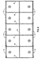
- FIG. 4 shows a variation of the first embodiment having 10 compartments arranged in two rows.
- a 10-compartment storage bag can be produced by cutting the work in process once every fifth work cycle, each work cycle comprising a respective advancement of the work in process and a respective dwell time.
- the interior cross seals 26 will have a width twice the width of the side seams 20 and 22, the latter being the result of bisecting similar cross seals.
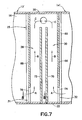
- FIG. 5 A two-compartment storage bag in accordance with a second embodiment of the invention is depicted in FIG. 5 .
- the zippers 8a, 8b and sliders 10a, 10b may be substantially similar to the corresponding components previously described with reference to FIG. 2 .
- the storage bag shown in FIG. 5 differs from the bag shown in FIG. 2 in that, instead of each compartment being evacuable by means of a respective one-way valve attached to a bag wall, a double valve assembly 25 is installed in a central region that runs parallel to the zippers, the double valve assembly being joined to the bag walls to form the fourth side of each of the two compartments 12' and 14'.
- the length of the double valve assembly 25 equals the width of the storage bag, with the marginal portions at the respective ends of the double valve assembly 25 being captured and sealed into the respective side seams 20 and 22 of the bag.
- the double valve assembly comprises a pair of rectangular strips 60 and 62 of valve making material (hereinafter “valve strips”) that are sandwiched between the front and rear walls 16 and 18.
- the valve strips 60 and 62 are joined to the bag walls 16 and 18 and to each other along the side seams (items 20 and 22 in FIG. 5 ).
- the valve strips 60 and 62 are also joined to each other and to the front and rear bag walls 16 and 18 in four band-shaped zones of joinder (indicated by dashed lines bounding solid hatching in FIG. 5 ) that extend generally parallel to the zippers 8a, 8b.
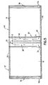
- These four band-shaped zones of joinder 66, 68, 70 and 72 are best seen in FIG. 7 , which represents a sectional view of the bag shown in FIG. 5 (the plane of sectioning passing through the zones of bag wall-to-valve strip joinder) with the rear bag wall and the valve strip adjacent the rear bag wall removed.
- One end of the channel 28 lies adjacent a first valve entry gap 31 disposed on the perimeter of the interior volume of the compartment 12' and extending from and perpendicular to the side seam 22, while the other end of the channel 28 lies adjacent an outlet 33 that is disposed adjacent to the side seam 20.
- the outlet 33 is formed by overlapping openings in the front bag wall 16 and the adjacent valve strip 60.
- the channel 30 is the mirror image of the channel 28. More specifically, one end of the channel 30 lies adjacent a second valve entry gap 32 disposed on the perimeter of the interior volume of the compartment 14' and extending from and perpendicular to the side seam 22, while the other end of the channel 30 lies adjacent the outlet 33.
- the short band-shaped zone 74 (indicated by dashed lines) represents a zone where the front wall 16 is joined to the valve strip 60.
- zone 74 the valve strips are not joined together, but the other valve strip (not shown in FIG. 7 ) is joined to the rear bag wall.
- Zone 74 extends from the side seam 22 to the termination point of the zone of joinder 66 and is collinear with the latter.
- the front wall 16 and the valve strip 60 are joined to each other and the rear wall and the other valve strip are joined to each other in a band-shaped zone (consisting of zones 66 and 74) that extends across the full width of the storage bag.
- valve_strips along the fourth side of compartment 14' are joined to each other in zone 66, but not in zone 74, the latter zone demarcating the extent of the valve entry gap 32. Accordingly, air from the interior volume of compartment 14' can enter elongated channel 30 only via the valve entry gap 32.
- the short band-shaped zone 76 (indicated by dashed lines in FIG. 7 ) represents a zone where the front wall 16 is joined to the valve strip 60.
- zone 76 the valve strips are not joined together, but the other valve strip (not shown in FIG. 7 ) is joined to the rear bag wall.
- Zone 76 extends from the side seam 22 to the termination point of the zone of joinder 68 and is collinear with the latter.
- the front wall 16 and the valve strip 60 are joined to each other and the rear wall and the other valve strip are joined to each other in a band-shaped zone (consisting of zones 68 and 76) that extends across the full width of the storage bag.
- valve strips along the fourth side of compartment 12' are joined to each other in zone 68, but not in zone 76, the latter zone demarcating the extent of the valve entry gap 31. Accordingly, air from the interior volume of compartment 12' can enter elongated channel 28 only via the valve entry gap 31.
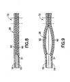
- FIGS. 8 and 9 are fragmentary sectional views of elongated channel 28, which is shown in a collapsed state ( FIG. 8 ) and a not collapsed state ( FIG. 9 ) respectively.
- the locations of tacking zone 76 and zone of joinder 72 are indicated by respective pairs of vertical dashed lines in FIG. 9 .
- tacking zone 76 the front wall 16 is tacked to the valve strip 60, the valve strip 60 is not tacked or otherwise joined to valve strip 62, and valve strip 62 is tacked to the rear wall 18.
- channel 28 is collapsed (as shown in FIG. 8 )
- air from the interior volume of compartment 12' cannot flow out the outlet 33.
- FIG. 9 shows the situation wherein the elongated channel 28 is not collapsed and the valve entry gap 31 is open.
- the corresponding compartment can be evacuated via that channel.
- FIG. 5 The flow path for exhausting air from the interior volume of compartment, 14' is represented by arrows A-C in FIG. 5 .
- Arrow A represents the flow of air from the interior volume of compartment 14', through the valve entry gap 32 and into the elongated channel 30.
- Arrow B represents the flow of air in the channel 30.
- Arrow C represents the flow of air from the channel 30 toward and then out the outlet 33.
- Such an air flow can be produced, e.g., by storing a compressible porous article in the interior volume of compartment 14', closing the zipper 8b to hermetically seal the mouth of the compartment 14', and then compressing the article as the compartment 14' is rolled up starting at the zipper 8b.
- the resulting air pressure causes the valve entry gap 32 and then the elongated channel 30 to open as air is squeezed out of the compartment 14'.
- the elongated channel 30 will again collapse due to ambient pressure, forming a hermetic seal that prevents air from re-entering the compartment 14' via the outlet 33.
- the valve strips are preferably made of a material that is smoother than the bag wall material.
- materials include, but are not limited to, low-density polyethylene (LDPE), linear low-density polyethylene (LLDPE) or polyethylene/EVOH/polyethylene.
- LDPE low-density polyethylene
- LLDPE linear low-density polyethylene
- the valve strips preferably each have a thickness of 2 mils, for a combined thickness of 4 mils. This thickness for the valve strips was found to provide the valve strips with sufficient stiffness to avoid conforming entirely to the adjacent bag wall films, and yet allow the valve strips to conform to some extent to one another, such that the valve strips sealingly close in the absence of pressure on the walls of the bag.
- first and second substantially identical strips of valve making film are respectively paid out from first and second valve film supply rolls, while first and second substantially identical webs of bag making film are respectively paid out from first and second bag film supply rolls.
- the valve making film may be smooth compared to the relatively rough surface of the bag making film.
- the respective widths of the valve strips and bag webs can be seen in FIG. 5 , wherein the width of the valve assembly 25 corresponds to the width of each valve strip, while the full height of the front wall 16 measured in a direction perpendicular to the zippers corresponds to the width of each web of bag making film.
- first valve strip and first bag web are guided to respective positions in immediate proximity to each other and with their respective centerlines overlapping.
- second valve strip and second bag web are guided to respective positions in immediate proximity to each other and with their respective centerlines overlapping.
- the first valve strip and first bag web travel intermittently and concurrently to a first valve film tacking station at which a first pair of tacking heads seal two elongated band-shaped portions of the first valve strip to corresponding portions of the first bag web during each dwell time (hereinafter referred to as "first and second tack seals").
- first and second tack seals a hole can be punched in both the first bag web and first valve strip that will ultimately become the outlet 33 shown in FIG. 7 .
- the second valve strip and second bag web travel intermittently and concurrently to a second valve film tacking station at which a second pair of tacking heads seal two elongated band-shaped portions of the second valve strip to corresponding portions of the second bag web during each dwell time (hereinafter referred to as "third and fourth tack seals").
- the four tack seals have the same length and width and all extend in the machine direction.
- the footprint of the first and second tack seals is substantially identical to the footprint of the third and fourth tack seals, so that when the respective tacked constructions are aligned with the first and second valve strips confronting each other, the first tack seal overlies the third tack seal, while the second tack seal overlies the fourth tack seal.
- the respective tacked constructions are then advanced intermittently toward a dual zipper application station.
- the webs of bag film are aligned and brought together in overlapping relationship with the valve strips facing and in contact with each other.
- a pair of substantially identical zipper tapes - each zipper tape comprising a respective pair of interlocked zipper strips - are paid out from first and second zipper tape supply reels respectively and guided into respective positions sandwiched between the respective marginal portions of the overlapping bag webs.
- the dual zipper application station comprises two pairs of mutually opposing, reciprocatable heated sealing bars that join the zipper tapes to the bag webs by conductive heat sealing.
- the amount of heat and pressure applied to the zipper tapes and marginal portions of the bag webs must be sufficient to cause the bag making film (or a sealant layer thereof in the case of a laminated film), to soften or melt and then fuse to the contacting zipper strip during cooling, but not so great as to cause the closure profiles of the zipper strips to fuse together.
- Alternative methods of zipper/web joinder can be utilized, such as adhesive application or ultrasonic welding.
- the section of the work in process that exits the dual zipper application station consists of the first and second bag webs in overlapping relationship, the left marginal portions of the first and second bag webs being joined to a first zipper tape situated therebetween, the right marginal portions of the first and second bag webs being joined to a second zipper tape situated therebetween, the first valve strip being tacked to a central portion of the first web and carried thereby, and the second valve strip being tacked to a central portion of the second web and carried thereby.
- This section of the work in process is then advanced intermittently to a dual ultrasonic welding station, where the zipper tapes are ultrasonically welded together to form respective zipper joints during each dwell time.
- the ultrasonic welding station may comprise an ultrasonic hom and an anvil, one or both of which is reciprocatable.
- sliders can be inserted on the zippers in a manner well known in the art.
- cross sealing station where a respective cross seal (see, e.g., cross seals 26 in FIG. 6 ) is formed during each dwell time.
- the cross sealing station may comprise a pair of mutually opposing, reciprocatable heated sealing bars that join the materials pressed therebetween when zipper tapes to the bag webs by conductive heat sealing.
- the cross sealing bars extend transversely across the full width of the bag webs.
- the cross sealing station is in registration with the ultrasonic welding station, so that each cross seal is aligned with and overlaps a respective zipper joint.
- sealing bars are staggered such that when the tacked bag web/valve strip construction is in proper registration, the sealing bars do not contact the zones of tack sealing, thereby ensuring that the valve strips in the tacking zones are not joined together and that the valve entry gaps are preserved.
- the work in process consists of a chain of storage bags, each storage bag comprising a respective double valve assembly of the type shown in FIG. 7 , with successive storage bags in the chain being connected by a respective cross seal.
- individual two-compartment bags are severed from one another by cutting along a line that bisects each successive cross seal, thereby forming respective side seams on the separated two-compartment bag and the leading two-compartment bag still attached to the work in process.
- Each severed two-compartment bag comprises a pair of overlapping rectangular sheets of flexible bag making material of a type previously described. These rectangular sheets form the front and rear walls of the two-compartment bag.
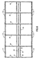
- FIG. 6 shows a variation of the second embodiment having 10 compartments arranged in two rows.
- a 10-compartment storage bag can be produced by cutting the work in process once every fifth work cycle, each work cycle comprising a respective advancement of the work in process and a respective dwell time.
- the interior cross seals 26 will have a width twice the width of the side seams 20 and 22, the latter being the result of bisecting similar cross seals.
- the verb "joined” means fused, welded, bonded, sealed, adhered, etc., whether by application of heat and/or pressure, application of ultrasonic energy, application of a layer of adhesive material or bonding agent, interposition of an adhesive or bonding strip, co-extrusion (e.g., of zipper and bag), etc.
- the prefix "multi” means two or more.
Landscapes
- Engineering & Computer Science (AREA)
- Mechanical Engineering (AREA)
- Bag Frames (AREA)
- Packages (AREA)
Applications Claiming Priority (2)
| Application Number | Priority Date | Filing Date | Title |
|---|---|---|---|
| US11/127,643 US7748904B2 (en) | 2005-05-12 | 2005-05-12 | Multicompartment evacuable storage bag |
| PCT/US2006/018283 WO2006124528A1 (en) | 2005-05-12 | 2006-05-11 | Multicompartment evacuable storage bag |
Publications (2)
| Publication Number | Publication Date |
|---|---|
| EP1879805A1 EP1879805A1 (en) | 2008-01-23 |
| EP1879805B1 true EP1879805B1 (en) | 2008-10-22 |
Family
ID=36791630
Family Applications (1)
| Application Number | Title | Priority Date | Filing Date |
|---|---|---|---|
| EP06759597A Not-in-force EP1879805B1 (en) | 2005-05-12 | 2006-05-11 | Multicompartment evacuable storage bag |
Country Status (9)
| Country | Link |
|---|---|
| US (1) | US7748904B2 (enExample) |
| EP (1) | EP1879805B1 (enExample) |
| JP (1) | JP2008540275A (enExample) |
| KR (1) | KR101210517B1 (enExample) |
| CN (1) | CN101193802B (enExample) |
| AU (1) | AU2006247733B2 (enExample) |
| CA (1) | CA2606761C (enExample) |
| DE (1) | DE602006003327D1 (enExample) |
| WO (1) | WO2006124528A1 (enExample) |
Families Citing this family (41)
| Publication number | Priority date | Publication date | Assignee | Title |
|---|---|---|---|---|
| US20050207679A1 (en) * | 2004-03-19 | 2005-09-22 | Armstrong Stephen G | Reclosable bag |
| US7290660B2 (en) | 2004-07-23 | 2007-11-06 | Tilman Paul A | Storage system having a disposable vacuum bag |
| JP2009509683A (ja) * | 2005-09-29 | 2009-03-12 | アルコン,インコーポレイティド | 二室型溶液包装システム |
| US9011003B2 (en) * | 2006-02-08 | 2015-04-21 | S.C. Johnson Home Storage, Inc. | Reclosable pouch and zipper for a reclosable pouch |
| AT503164B1 (de) * | 2006-02-10 | 2007-11-15 | Mam Babyartikel | Gefrierbeutel |
| GB2437723A (en) * | 2006-05-03 | 2007-11-07 | Robert Thomas Hill | Flexible waterproof flood protection container |
| US20080069484A1 (en) * | 2006-09-20 | 2008-03-20 | Jackman Thomas J | Polystyrene bag with polyethylene zipper |
| US7857514B2 (en) | 2006-12-12 | 2010-12-28 | Reynolds Foil Inc. | Resealable closures, polymeric packages and systems and methods relating thereto |
| US20080304771A1 (en) * | 2007-06-05 | 2008-12-11 | Charles Harder | Vacuum storage bag with zipper |
| US20090034885A1 (en) * | 2007-08-03 | 2009-02-05 | Mcgruder John N | Deli sandwich/composite storage bag |
| US20090142006A1 (en) * | 2007-11-30 | 2009-06-04 | N.S. Flexibles, Llc | Multicompartment bag having resealable opposed openings |
| US8328421B2 (en) * | 2008-01-30 | 2012-12-11 | S.C. Johnson & Son, Inc. | Push-down compressible pouch with one-way valves on sides |
| US20090214140A1 (en) * | 2008-02-22 | 2009-08-27 | Torie Sue Jacobson | Multiple compartment self-sealing plastic bag |
| US20090257685A1 (en) * | 2008-04-14 | 2009-10-15 | Illinois Tool Works Inc. | Flexible storage bag with vent between two zipper |
| US20100086238A1 (en) * | 2008-10-02 | 2010-04-08 | Victoria Sprehe | Bag with a pocket for a thermal insulating material and method of making same |
| US20100142862A1 (en) * | 2008-12-05 | 2010-06-10 | Bassam Abed Sam | Container bag with multiple sealable locks |
| US20100159096A1 (en) * | 2008-12-05 | 2010-06-24 | Bassam Abed Sam | Container bag with multiple sealable locks |
| US20100142861A1 (en) * | 2008-12-05 | 2010-06-10 | Bassam Abed Sam | Container bag with multiple sealable locks |
| WO2011089588A1 (en) * | 2010-01-24 | 2011-07-28 | Paskal Zippers Ltd. | A waterproof zipper and manufacturing method therefor |
| GB2481228B (en) * | 2010-06-16 | 2013-08-21 | Brace S Bakery Ltd | Packaging |
| JP4673929B1 (ja) * | 2010-06-17 | 2011-04-20 | 有限会社田中テクニカル | シート製の逆止弁構造 |
| CN103153803B (zh) * | 2010-09-21 | 2015-11-25 | 艾利丹尼森公司 | 具有配套监控装置的可再封闭真空储物袋及其使用方法 |
| US8573845B2 (en) * | 2011-03-21 | 2013-11-05 | The Turover Straus Group, Inc. | Apparatus, systems and methods for preparing food in packages having integral compartments |
| USD699343S1 (en) | 2011-12-20 | 2014-02-11 | Alcon Research, Ltd. | Irrigation solution bag |
| CN105564737A (zh) * | 2012-02-28 | 2016-05-11 | 株式会社高园 | 包装袋 |
| JP6060148B2 (ja) | 2012-02-28 | 2017-01-11 | 株式会社タカゾノ | 錠剤包装装置及び包装袋 |
| CN102633038A (zh) * | 2012-04-24 | 2012-08-15 | 金红叶纸业集团有限公司 | 干湿两用纸巾包装袋 |
| CN102745392A (zh) * | 2012-08-03 | 2012-10-24 | 陈伟平 | 一种双袋式密封袋及其制作方法 |
| CN102910352A (zh) * | 2012-09-24 | 2013-02-06 | 李一鸣 | 立体包装袋 |
| USD725195S1 (en) | 2013-09-12 | 2015-03-24 | Velma L. Howard | Label |
| US9169055B1 (en) * | 2014-04-30 | 2015-10-27 | Patrick Gwen | Desiccant container |
| JP2016055878A (ja) * | 2014-09-05 | 2016-04-21 | 東洋自動機株式会社 | 気体流路付き袋並びに袋の包装方法及び装置 |
| US20160221722A1 (en) * | 2015-02-03 | 2016-08-04 | 365-Sports, LLC | Sealable Storage Bag and Related Methods |
| ES1138392Y (es) * | 2015-03-20 | 2015-07-06 | Sanchez Gonzalo Jesus Roman | Envase para lonchas de productos alimentarios |
| CN105836271B (zh) * | 2016-05-22 | 2017-11-21 | 重庆市巨恒塑料有限公司 | 一种易立式塑料编织袋 |
| US20200010248A1 (en) * | 2018-07-05 | 2020-01-09 | New York Packaging Ii | Multi-compartment sealable bag apparatus and methods of manufacture thereof |
| CN111253729B (zh) * | 2020-03-19 | 2022-07-12 | 浙江伟星实业发展股份有限公司 | 一种环保注塑拉链用材料、拉链链牙、其制备方法及拉链 |
| US11297915B1 (en) | 2020-12-07 | 2022-04-12 | QBSleeves, Inc. | Airplane tray cover multi-compartment holder system and method |
| US11220371B1 (en) | 2020-12-07 | 2022-01-11 | QBSleeves, Inc. | Airplane tray cover multi-compartment holder system and method |
| IL295959A (en) * | 2022-08-25 | 2024-03-01 | Keter Elimelech | A method for removing hand tefillin from the tefillin bag before removing head tefillin |
| US20240262551A1 (en) * | 2023-02-06 | 2024-08-08 | William Cho | Oppositely sealed multi-compartment heat-sealable bag for food storage |
Family Cites Families (30)
| Publication number | Priority date | Publication date | Assignee | Title |
|---|---|---|---|---|
| US2063850A (en) * | 1936-05-18 | 1936-12-08 | Nemeth & Adam Inc | Lady's handbag |
| US3207420A (en) * | 1964-05-19 | 1965-09-21 | Octaviano D Navarrete-Kindelan | Container |
| US3490576A (en) * | 1967-06-12 | 1970-01-20 | Standard Packaging Corp | Air evacuated package |
| FR2512424A1 (fr) * | 1981-09-10 | 1983-03-11 | Collet Cafes | Sachet d'emballage sous vide |
| JPH0310218U (enExample) * | 1989-06-20 | 1991-01-31 | ||
| US5024536A (en) * | 1990-07-16 | 1991-06-18 | Hill Diane E | Resealable compartmented bags |
| JPH0692361A (ja) * | 1992-09-01 | 1994-04-05 | Bridgestone Corp | 袋 体 |
| US5540500A (en) * | 1994-04-25 | 1996-07-30 | Nichimen Corporation | Compressive sealed bag for compressible articles such as clothing and the same |
| JPH07309351A (ja) | 1994-05-17 | 1995-11-28 | Idemitsu Petrochem Co Ltd | 咬合具付き袋 |
| KR100371671B1 (ko) * | 1994-05-17 | 2003-05-17 | 이데미쓰세끼유가가꾸가부시끼가이샤 | 스냅이부착된자루 |
| US5584409A (en) * | 1995-09-18 | 1996-12-17 | Chemberlen; Christopher H. | One direction ventilation valves |
| US6059457A (en) | 1998-01-02 | 2000-05-09 | Com-Pac International, Inc. | Evacuable storage bag with integral zipper seal |
| US6595689B1 (en) * | 1999-06-10 | 2003-07-22 | The Glad Products Company | Closure device |
| US6116781A (en) | 1999-08-13 | 2000-09-12 | New West Products, Inc. | Storage bag with one-way air valve |
| US6357915B2 (en) * | 1999-08-13 | 2002-03-19 | New West Products, Inc. | Storage bag with one-way air valve |
| ATE277836T1 (de) * | 1999-12-09 | 2004-10-15 | Schur Consumer Products As | Beutel zum bewahren und spülen eines produktes |
| US20020067865A1 (en) | 2000-12-06 | 2002-06-06 | Stutzman Todd L. | Food storage bags with multiple compartments |
| JP3579660B2 (ja) * | 2001-04-20 | 2004-10-20 | 有限会社アピィール | 脱気袋 |
| JP3563713B2 (ja) * | 2001-07-25 | 2004-09-08 | 千也 田中 | 物品の密封収容袋 |
| US6729473B2 (en) * | 2002-06-20 | 2004-05-04 | Cti Industries Corporation | Air-evacuable bag with double-layered valve film and method for manufacturing same |
| US6983845B2 (en) * | 2002-06-28 | 2006-01-10 | S.C. Johnson Home Storage, Inc. | Recloseable storage bag with user-deformable air vent |
| US6752264B2 (en) * | 2002-07-03 | 2004-06-22 | Sonoco Development, Inc. | Flexible pouch having system for mixing two components |
| AU2002335342A1 (en) * | 2002-09-04 | 2004-04-08 | Ishizaki Shizai Co., Ltd. | Compressive accommodation bag having non-return valve function |
| US20040050745A1 (en) * | 2002-09-13 | 2004-03-18 | Lee William Jonathon | Bag for vacuum sealing an item within |
| CN2595698Y (zh) * | 2003-01-13 | 2003-12-31 | 薛裕仁 | 包装袋的阻气阀 |
| CN2658084Y (zh) * | 2003-07-02 | 2004-11-24 | 张菁华 | 固体物料的多容腔多物料包装袋 |
| JP3677515B1 (ja) * | 2004-01-10 | 2005-08-03 | 株式会社アール | 圧縮袋の製造方法及び圧縮袋及び空気通路の構造 |
| US20080107781A1 (en) * | 2006-11-06 | 2008-05-08 | Christopher Carroll | Food container |
| US20080159660A1 (en) * | 2006-12-29 | 2008-07-03 | Roell Iii Robert L | System to remove air from a bag |
| US7674041B2 (en) * | 2007-03-14 | 2010-03-09 | Cryovac, Inc. | Packaging device and method of using the same |
-
2005
- 2005-05-12 US US11/127,643 patent/US7748904B2/en not_active Expired - Fee Related
-
2006
- 2006-05-11 DE DE602006003327T patent/DE602006003327D1/de active Active
- 2006-05-11 WO PCT/US2006/018283 patent/WO2006124528A1/en not_active Ceased
- 2006-05-11 KR KR1020077025672A patent/KR101210517B1/ko not_active Expired - Fee Related
- 2006-05-11 EP EP06759597A patent/EP1879805B1/en not_active Not-in-force
- 2006-05-11 JP JP2008511370A patent/JP2008540275A/ja active Pending
- 2006-05-11 CN CN2006800206012A patent/CN101193802B/zh not_active Expired - Fee Related
- 2006-05-11 CA CA2606761A patent/CA2606761C/en not_active Expired - Fee Related
- 2006-05-11 AU AU2006247733A patent/AU2006247733B2/en not_active Ceased
Also Published As
| Publication number | Publication date |
|---|---|
| KR101210517B1 (ko) | 2012-12-10 |
| WO2006124528A1 (en) | 2006-11-23 |
| DE602006003327D1 (de) | 2008-12-04 |
| CA2606761C (en) | 2010-11-02 |
| KR20080014761A (ko) | 2008-02-14 |
| AU2006247733B2 (en) | 2010-04-29 |
| US20060257054A1 (en) | 2006-11-16 |
| AU2006247733A1 (en) | 2006-11-23 |
| EP1879805A1 (en) | 2008-01-23 |
| CN101193802B (zh) | 2010-04-14 |
| CN101193802A (zh) | 2008-06-04 |
| CA2606761A1 (en) | 2006-11-23 |
| US7748904B2 (en) | 2010-07-06 |
| JP2008540275A (ja) | 2008-11-20 |
Similar Documents
| Publication | Publication Date | Title |
|---|---|---|
| EP1879805B1 (en) | Multicompartment evacuable storage bag | |
| US7347908B2 (en) | Leakproof zipper end crush for reclosable bag and related method of manufacture | |
| US7553082B2 (en) | Evacuable storage bag having resealable means activated by slider | |
| US6231236B1 (en) | Resealable package having venting structure and methods | |
| EP1366999B1 (en) | Reclosable packaging | |
| US6533456B1 (en) | Reclosable stand-up package, and methods | |
| US7527585B2 (en) | Methods of making reclosable packages for vacuum, pressure and/or liquid containment | |
| US8961014B2 (en) | Compressible pouch with multiple collapsible channels across bottom | |
| US5988880A (en) | Resealable closure mechanism | |
| US20090052808A1 (en) | Resealable and evacuable hanging bag with removable hanging device | |
| US20060093242A1 (en) | Reclosable packages for vacuum, pressure and/or liquid containment | |
| JPH11314650A (ja) | 再閉鎖可能なパッケ―ジおよびそのジッパ帯 | |
| JP2007008589A (ja) | 再閉鎖可能な貯蔵用バッグ | |
| US8328421B2 (en) | Push-down compressible pouch with one-way valves on sides | |
| US7490989B2 (en) | Slider for operating zipper of evacuable storage bag | |
| US20090190864A1 (en) | Airtight evacuable storage bag and related method of manufacture | |
| US10065387B2 (en) | Reclosable pouch with leakproof closure and method of manufacture | |
| US7182513B1 (en) | Zipper strip and method of positioning the strip transverse longitudinal axis |
Legal Events
| Date | Code | Title | Description |
|---|---|---|---|
| PUAI | Public reference made under article 153(3) epc to a published international application that has entered the european phase |
Free format text: ORIGINAL CODE: 0009012 |
|
| 17P | Request for examination filed |
Effective date: 20071129 |
|
| AK | Designated contracting states |
Kind code of ref document: A1 Designated state(s): DE FR GB |
|
| GRAP | Despatch of communication of intention to grant a patent |
Free format text: ORIGINAL CODE: EPIDOSNIGR1 |
|
| RBV | Designated contracting states (corrected) |
Designated state(s): DE FR GB |
|
| DAX | Request for extension of the european patent (deleted) | ||
| GRAS | Grant fee paid |
Free format text: ORIGINAL CODE: EPIDOSNIGR3 |
|
| GRAA | (expected) grant |
Free format text: ORIGINAL CODE: 0009210 |
|
| AK | Designated contracting states |
Kind code of ref document: B1 Designated state(s): DE FR GB |
|
| REG | Reference to a national code |
Ref country code: GB Ref legal event code: FG4D |
|
| REF | Corresponds to: |
Ref document number: 602006003327 Country of ref document: DE Date of ref document: 20081204 Kind code of ref document: P |
|
| PLBE | No opposition filed within time limit |
Free format text: ORIGINAL CODE: 0009261 |
|
| STAA | Information on the status of an ep patent application or granted ep patent |
Free format text: STATUS: NO OPPOSITION FILED WITHIN TIME LIMIT |
|
| 26N | No opposition filed |
Effective date: 20090723 |
|
| REG | Reference to a national code |
Ref country code: FR Ref legal event code: TP Owner name: S.C. JOHNSON & SON, INC., US Effective date: 20130121 |
|
| REG | Reference to a national code |
Ref country code: GB Ref legal event code: 732E Free format text: REGISTERED BETWEEN 20130815 AND 20130821 |
|
| REG | Reference to a national code |
Ref country code: DE Ref legal event code: R081 Ref document number: 602006003327 Country of ref document: DE Owner name: S.C. JOHNSON & SON, INC. (N.D.GES.D. STAATES W, US Free format text: FORMER OWNER: ILLINOIS TOOL WORKS INC., GLENVIEW, US Effective date: 20131122 Ref country code: DE Ref legal event code: R081 Ref document number: 602006003327 Country of ref document: DE Owner name: S.C. JOHNSON & SON, INC. (N.D.GES.D. STAATES W, US Free format text: FORMER OWNER: ILLINOIS TOOL WORKS INC., GLENVIEW, ILL., US Effective date: 20131122 |
|
| PGFP | Annual fee paid to national office [announced via postgrant information from national office to epo] |
Ref country code: GB Payment date: 20140527 Year of fee payment: 9 |
|
| PGFP | Annual fee paid to national office [announced via postgrant information from national office to epo] |
Ref country code: DE Payment date: 20140529 Year of fee payment: 9 Ref country code: FR Payment date: 20140519 Year of fee payment: 9 |
|
| REG | Reference to a national code |
Ref country code: DE Ref legal event code: R119 Ref document number: 602006003327 Country of ref document: DE |
|
| GBPC | Gb: european patent ceased through non-payment of renewal fee |
Effective date: 20150511 |
|
| REG | Reference to a national code |
Ref country code: FR Ref legal event code: ST Effective date: 20160129 |
|
| PG25 | Lapsed in a contracting state [announced via postgrant information from national office to epo] |
Ref country code: DE Free format text: LAPSE BECAUSE OF NON-PAYMENT OF DUE FEES Effective date: 20151201 Ref country code: GB Free format text: LAPSE BECAUSE OF NON-PAYMENT OF DUE FEES Effective date: 20150511 |
|
| PG25 | Lapsed in a contracting state [announced via postgrant information from national office to epo] |
Ref country code: FR Free format text: LAPSE BECAUSE OF NON-PAYMENT OF DUE FEES Effective date: 20150601 |