EP1879498B1 - Verfahren und vorrichtung zur analyse der lungenleistung - Google Patents
Verfahren und vorrichtung zur analyse der lungenleistung Download PDFInfo
- Publication number
- EP1879498B1 EP1879498B1 EP06770214.2A EP06770214A EP1879498B1 EP 1879498 B1 EP1879498 B1 EP 1879498B1 EP 06770214 A EP06770214 A EP 06770214A EP 1879498 B1 EP1879498 B1 EP 1879498B1
- Authority
- EP
- European Patent Office
- Prior art keywords
- gas
- flow rate
- test
- patient
- inspired
- Prior art date
- Legal status (The legal status is an assumption and is not a legal conclusion. Google has not performed a legal analysis and makes no representation as to the accuracy of the status listed.)
- Expired - Lifetime
Links
Images


Classifications
-
- A—HUMAN NECESSITIES
- A61—MEDICAL OR VETERINARY SCIENCE; HYGIENE
- A61B—DIAGNOSIS; SURGERY; IDENTIFICATION
- A61B5/00—Measuring for diagnostic purposes; Identification of persons
- A61B5/08—Measuring devices for evaluating the respiratory organs
- A61B5/087—Measuring breath flow
- A61B5/0875—Measuring breath flow using means carried by the fluid stream, e.g. free-floating balls
-
- A—HUMAN NECESSITIES
- A61—MEDICAL OR VETERINARY SCIENCE; HYGIENE
- A61B—DIAGNOSIS; SURGERY; IDENTIFICATION
- A61B5/00—Measuring for diagnostic purposes; Identification of persons
- A61B5/08—Measuring devices for evaluating the respiratory organs
- A61B5/0813—Measurement of pulmonary parameters by tracers, e.g. radioactive tracers
-
- A—HUMAN NECESSITIES
- A61—MEDICAL OR VETERINARY SCIENCE; HYGIENE
- A61B—DIAGNOSIS; SURGERY; IDENTIFICATION
- A61B5/00—Measuring for diagnostic purposes; Identification of persons
- A61B5/08—Measuring devices for evaluating the respiratory organs
- A61B5/091—Measuring volume of inspired or expired gases, e.g. to determine lung capacity
-
- A—HUMAN NECESSITIES
- A61—MEDICAL OR VETERINARY SCIENCE; HYGIENE
- A61B—DIAGNOSIS; SURGERY; IDENTIFICATION
- A61B5/00—Measuring for diagnostic purposes; Identification of persons
- A61B5/08—Measuring devices for evaluating the respiratory organs
- A61B5/097—Devices for facilitating collection of breath or for directing breath into or through measuring devices
-
- A—HUMAN NECESSITIES
- A61—MEDICAL OR VETERINARY SCIENCE; HYGIENE
- A61B—DIAGNOSIS; SURGERY; IDENTIFICATION
- A61B5/00—Measuring for diagnostic purposes; Identification of persons
- A61B5/72—Signal processing specially adapted for physiological signals or for diagnostic purposes
- A61B5/7225—Details of analogue processing, e.g. isolation amplifier, gain or sensitivity adjustment, filtering, baseline or drift compensation
-
- A—HUMAN NECESSITIES
- A61—MEDICAL OR VETERINARY SCIENCE; HYGIENE
- A61B—DIAGNOSIS; SURGERY; IDENTIFICATION
- A61B5/00—Measuring for diagnostic purposes; Identification of persons
- A61B5/72—Signal processing specially adapted for physiological signals or for diagnostic purposes
- A61B5/7235—Details of waveform analysis
- A61B5/7264—Classification of physiological signals or data, e.g. using neural networks, statistical classifiers, expert systems or fuzzy systems
Definitions
- the invention relates generally to pulmonary function testing and particularly to a device and method for measuring pulmonary functions in real-time or near real-time using controlled sample gas injection into the gas delivery system.
- Trace gases in the inspired gas mixtures include carbon monoxide and acetylene (each of which is used to measure gas diffusion across the alveoli) and helium and methane (each of which is used to measure the dead space in the lung cavity and/or pulmonary testing device).
- carbon monoxide and acetylene absorb readily and rapidly into the bloodstream while helium and methane do not.
- the volumes of the carbon monoxide or acetylene component and the helium or methane in the inspired and/or expired gas are determined and used along with the known composition of the sample gas, to calculate the volume of carbon monoxide or acetylene absorbed by the lungs.
- Carbon dioxide concentration in the expired gas can also be measured to ascertain lung diffusion because the concentration of carbon dioxide is directly related to the amount of oxygen absorbed into the bloodstream.
- the device 100 includes a breathing conduit 104 that includes a patient mouthpiece 108, first and second outlets 112 and 116 for the discharge of exhaled air and intake of ambient inhaled air, respectively, and a test gas intake assembly 120. Balloon valves 124 and 128 open and close respectively the outlets 112 and 116.
- the test gas intake assembly 120 comprises a diaphragm 132 biased by a spring 136 and connected to a closure arm 140 that opens and closes the test gas introduction port 144 of conduit 148 upon demand (referred to as a demand valve).
- the diaphragm 132 When the patient closes the balloons 124 and 128 and inhales, the diaphragm 132 is drawn downwards and the closure arm 140 repositioned as shown by the dotted lines. In this position, the port 144 is opened, thereby introducing pressurized test gas of known composition into the device 100 via conduit 148. The test gas is subsequently inhaled by the patient via the patient mouthpiece 108.
- a series of gas component sensors denoted by block 152 measure the concentrations of various selected gas components in the inspired and/or expired gas stream(s). Additionally, a gas flow measuring device 156 measures the flow rate of the inspired and/or expired gas stream, as desired.
- V X V F ⁇ V X - F X - F A ⁇ V DS
- V F the total gas volume actually inspired by the patient
- F X the fraction of the selected gas component in the tank volume
- F A is the concentration of the selected gas component in the ambient atmosphere (or in the device 100 before the test)
- V DS is the interior volume of device 100 (dead space volume).
- exhaled gas concentration measurements will allow estimations of the lung volume at the start of inhalation.
- gas such as carbon monoxide that has a high diffusivity through the alveoli
- exhaled gas concentration measurements will provide an estimate of the lung diffusion properties.
- This device 100 can have disadvantages. For example, it can be complex, expensive, physically large and unwieldy, and difficult to use. It typically may not be used for a number of pulmonary tests, such as pulmonary tests conducted while the patient is exercising.
- the pre-mixed gases used in pulmonary function and lung mechanics testing can also be costly.
- the logistics associated with the ordering, storing, and disposal of the specialized gas cylinders also add to the complexity of the operation of a pulmonary function laboratory.
- the present invention can measure a variety of lung functions and mechanics using a breathing device in which the test gas is introduced without the use of demand valves.
- the device uses open, opposing ends and is free of valves, such as demand valves, positioned in the breathing. Inhalation of test gas is effected by the use of gas injections.
- the gas delivery system can be digitally controlled to provide a test gas at varying flow rates and compositions.
- the test gas is stored in small single or multi-use cartridges and is provided to the patient during inhalation.
- the cartridges are substantially smaller than specialized gas cylinders of the prior art and thus may be easily stored and used in virtually any medical setting.
- the device of the present invention can have a number of advantages. For example, it can be simple, lightweight, inexpensive, physically small, and easy to use. It can be digitally controlled and provide variable gas compositions at variable flow rates. The device can be readily adapted to a variety of pulmonary and cardiac tests, including stress testing. It can provide an extremely low resistance to patient inspiration, which can be important not only for test accuracy but also for patients with chronic lung conditions.
- a pulmonary testing device comprising:
- the at least one test gas injector may be positioned in and/or near the second end such that the gas injector can provide test gas to the second end.
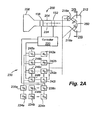
- the device includes a breathing conduit 204 having a patient mouthpiece 208 on one end and a test gas introduction inlet 212 on the other end.
- a plurality of injectors 216a-h are positioned in the test gas introduction inlet 212 to provide desired test gases into the inlet 212 from a pressurized gas source.
- gas flow measuring device 156 Positioned between the two ends of the conduit 204 are gas flow measuring device 156 and a set of gas component sensors or gas analyzers denoted by block 152.
- a controller 220 receives measurement signals from the device 156 and sensors, uses the measurements to determine pulmonary (lung) parameters, such as diffusion, and lung capacity, and, based thereon, control test gas introduction or flow rates through the injectors 216a-h and controls the test gas composition provided to the injectors 216a-h, the injection of the test gas during inspiration, and the termination of test gas injection during expiration.
- pulmonary (lung) parameters such as diffusion, and lung capacity
- the breathing conduit 204 is open at either end and preferably provides little, if any, resistance to patient inhalation (which can be important for patients with chronic lung conditions). In other words when test gas is not being introduced through the injectors, the patient can breathe ambient air by placing his mouth over the mouthpiece 208 and inhaling, which will draw ambient air through the open inlet 212. It is also desirable for breathing conduit 204 to have a small volume (dead space) to minimize the amount of re-breathed gas.
- the conduit 204 can be of any composition but preferably is plastic.
- the injectors 216a-h preferably have an outlet orifice that is smaller than the diameter of the body of the injectors 216a-h to introduce the test gas into the inlet 212 at a higher velocity than the flow velocity through the injector body.
- the injectors are angled away from the patient to introduce gas in a direction of flow that is away from the patient. This injector orientation avoids forcing test gas into the patient's lungs, which would otherwise decrease the accuracy of the test.
- the angle ⁇ measured relative to the horizontal center line 224 of the conduit 204 is less than 90 degrees and preferably ranges from about 10 to about 75 degrees.
- injectors any number or configuration of injectors may be used so long as the test gas wall 250 is maintained.
- variable flow rate injectors are discussed herein, it is to be understood that fixed flow rate injectors may be used with the fixed flow rate being sufficient to maintain the test gas wall 250.
- the gas flow measuring device 200 can be device capable of measuring gas flow, including without limitation a pneumatach, an ultrasonic emitter and receiver, a variable orifice, a transducer, and combinations thereof.
- the gas sensors or analyzers 152 typically include a plurality of gas sensors for measuring each selected gas component.
- the sensors are preferably distributed substantially uniformly across the cross-section of the conduit passage to provide more accurate gas component measurements. Any suitable gas sensors can be employed.
- the controller 220 can be any suitable processor, including a microprocessor, and typically includes a memory for storing measurements, computational control and derivation modules, and other information. Although a digital gas delivery system is depicted in Fig. 2 , it is to be understood that the concepts of the present invention work equally well with an analog gas delivery system.
- a test gas supply assembly 230 is controlled by the controller 220 and provides a test gas of a desired composition at a desired flow rate.
- the assembly 230 includes a plurality of gas storage vessels 234a-n, each having a different gas composition ("G"), and a corresponding plurality of valves (“V”) 238a-n controlling flow out of the vessels.
- the assembly 230 includes a plurality of flow restrictors ("R") 242a-i of different orifice sizes and corresponding flow valves ("V”) 246a-i for controlling gas flow through the corresponding flow restrictor 242.
- Dashed lines represent gas flow lines for transporting gas to the injectors 216 while solid lines represent signaling control lines for conveying digital commands from the controller 220 to the various valves 246a-i and 238a-n.
- each of the flow restrictors is a product of X with a selected flow factor (e.g ., weigh the orifices in a binary scheme, such as the flow rate through valve 242a being 8X, through valve 242b being 4X, through valve 242c being 2X, and through valve 242i being X, which would provide sixteen different flow rates adjustable by a four-bit binary code), and that each of the vessels 234a-n contains a different gas component (e.g ., vessel 234a contains carbon monoxide or acetylene, vessel 234b helium or methane, and vessel 234n molecular oxygene).
- a selected flow factor e.g ., weigh the orifices in a binary scheme, such as the flow rate through valve 242a being 8X, through valve 242b being 4X, through valve 242c being 2X, and through valve 242i being X, which would provide sixteen different flow rates adjustable by a four-bit binary code
- the controller 220 can deliver a gas comprising a mixture of carbon monoxide or acetylene on the one hand and helium or methane on the other at a selected flow rate by opening valves 238a and b and a selected one or combination of valves 246a-i.
- each vessel 234 can include a mixture of gas components or a single vessel containing a selected mixture of gas components can replace all of the vessels depending on the application.
- the configuration of Fig. 2 can provide a simple, controllable and versatile pulmonary testing device.
- pulmonary testing device 200 The operation of the pulmonary testing device 200 will now be described with reference to Figs. 2A , and 3-5 .
- the controller 220 introduces a test gas mixture through the injectors 216 at a flow rate that provides a test gas volume over a selected period of time that is greater than the volume of gas that the patient will likely inspire over the same time period.
- the uniform distribution of test gas across the cross-section of the conduit 204 effectively provides a "wall" 250 of test gas that blocks or inhibits the flow of ambient air through the conduit 200 and into the patient's lungs.
- the requisite gas flow rate through the injectors depends on the number of gas injectors employed.
- the controller 220 issues commands to the valves 246a-i as required to simultaneously and equally decrease or increase the flow rates through the injectors to maintain a bulk introduction gas flow rate that is sufficient to compensate for the gas being inspired by the patient.
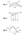
- the curve 500 represents the collective flow rate through injectors that, at any point in time, is effectively equal to the flow rate through the conduit as measured by the flow rate sensor 156.
- the collective flow rate 504 through the injectors is maintained, over a selected time interval, at a magnitude that is greater than the flow rates on the curve over the same interval.
- the flow rate through the injectors is maintained at a selected flow rate greater than the flow rates on the curve, where the selected flow rate is sufficient to maintain the test gas wall 250.
- the controller 220 measures the current flow rate, determines the rate of change of the flow rate over a selected number of preceding time intervals, and, based on this information, predicts a likely flow rate over the subsequent time interval.
- the control signal sent to the valves 246a-i for valve control in the subsequent time interval is generally based on that prediction.
- the inspired and/or expired gas component volumes can be determined using measurements from the flow and gas concentration sensors 156 and 152, respectively.
- Fig. 3 shows a typical patient inspiration curve 300 for a selected gas component X.
- the area under the curve represents the total volume of gas component X inspired by the patient over the time interval T 0 to T n .
- the area may be determined using any known mathematical algorithms, such as integration.
- V X is the total volume of a selected gas component inspired by the patient
- dV 1 dt is the inspired flow rate over a sample interval (measured by the gas flow measuring device 156)
- F X is the fraction of the inspired gas flow during the sample interval that represents component X (measured by the gas sensors 152)
- ⁇ T i is the sample interval (which is usually the time interval between successive measurements).
- the various products are summed over the duration of the pulmonary test, which varies depending on the type of test being conducted.
- Fig. 4 shows a series of sample time intervals, T 1 - T 2 , T 2 - T 3 , and T 3 - T 4 .
- the dV 1 dt in each sample time interval is the average flow rate measured over each sample interval.
- dV 1 dt can be determined in a number of ways, such as the median flow rate and the like. Using this equation, the dead space in the device 200 is substantially unimportant because of the accuracy of the algorithm in determining the volume of each component inspired into the lungs.
- the gathered measurements can be used to perform a number of pulmonary tests.
- the measurements can be used to determine lung volume, such as using gas wash-in methods (e.g., m olecular nitrogen washout using molecular oxygen inspiration, methane single breath dilution, and multi-breath equilibration), (capillary and/or membrane) diffusion, such as using carbon monoxide or acetylene absorption coupled with a non-absorbable gas, and other lung mechanics and pulmonary function known to those of ordinary skill in the art.
- the device 200 is particularly useful in performing one or more of the foregoing tests while the patient is exercising.
- the device 200 can be lightweight, easily manipulated by the patient, and can provide (without using a new device 200) a varying inspired gas composition depending on the particular test desired.
- a flow rate Of Sample gas is injected that is not sufficient to maintain a wall 250 of sample gas.
- ambient air is permitted to enter into the conduit 204 for inspiration by the patient while a sample gas is introduced through the injector(s).
- the sample gas could be a single gas component or a mixture of gas components.
- the gas analyzers would permit the fraction of the inspired volume represented by a target gas component to be readily and accurately determined notwithstanding the presence of non-test gas components from the ambient atmosphere. This embodiment has the advantage of using a lesser volume of sample gas in the test, which can represent a significant cost savings.
- a single component sample gas such as a single component carbon monoxide or acetylene gas
- a vessel 234 of a sufficient small volume that if the device 200 malfunctioned and introduced the entire volume of the vessel234 into the conduit 204 the patient's health would not be compromised.
- the concentration of the gas component can be limited to a safe maximum value such that it will not pose a health hazard even under prolonged breathing conditions.
- a small quantity of the test gas component(s) is stored in a small gas cartridge 620 at high concentrations (up to 100%).
- a 2 ml gas cartridge storing 100% CO at 50 psi can provide over 1000 ppm of CO to a patient with an inspiratory capacity of 5 liters.
- the gas cartridge 620 is connected to the breathing conduit 604 through a valve mechanism.
- the valve mechanism can be an electrically actuated solenoid valve 616 or other suitable mechanisms.
- the valve 616 is actuated after the initiation of inspiring effort at an appropriate point during the test.
- the test gas stored in the gas cartridge 620 is discharged into the breathing conduit 604 to be inhaled by the patient.
- a restrictor in series with the valve 616 can also be employed to extend the gas discharge time to a few seconds to limit the peak concentration of gas component thereby reducing the dynamic range requirements for the gas sensors/analyzers 652. Similar to other embodiments, the flow sensor 656 and the gas sensors/analyzers 652 measure the total volume of test gas component inhaled.
- This embodiment has the advantage of eliminating the need for gas lines connecting the test gas source and the pulmonary test device.
- the small gas cartridge 620 preferably a single use item, can be easily stored and procured.
- the small size of the cartridge also ensures patient safety even if the entire content is discharged rapidly.
- the present invention in various embodiments, includes components, methods, processes, systems and/or apparatus substantially as depicted and described herein, including 35 various embodiments, subcombinations, and subsets thereof. Those of skill in the art will understand how to make and use the present invention after understanding the present disclosure.
Landscapes
- Health & Medical Sciences (AREA)
- Life Sciences & Earth Sciences (AREA)
- Engineering & Computer Science (AREA)
- Pulmonology (AREA)
- Physics & Mathematics (AREA)
- Surgery (AREA)
- Veterinary Medicine (AREA)
- Biophysics (AREA)
- Biomedical Technology (AREA)
- Heart & Thoracic Surgery (AREA)
- Medical Informatics (AREA)
- Molecular Biology (AREA)
- Physiology (AREA)
- Animal Behavior & Ethology (AREA)
- General Health & Medical Sciences (AREA)
- Public Health (AREA)
- Pathology (AREA)
- Signal Processing (AREA)
- Artificial Intelligence (AREA)
- Computer Vision & Pattern Recognition (AREA)
- Psychiatry (AREA)
- Power Engineering (AREA)
- Evolutionary Computation (AREA)
- Fuzzy Systems (AREA)
- Mathematical Physics (AREA)
- Measurement Of The Respiration, Hearing Ability, Form, And Blood Characteristics Of Living Organisms (AREA)
- Investigating Or Analysing Biological Materials (AREA)
Claims (13)
- Vorrichtung zur Prüfung der Lungenfunktion, umfassend:Erste und zweite Enden (208, 212) einer Röhre (204), wobei das erste Ende ein Mundstück für einen Patienten umfasst und das zweite Ende zur Umgebungsatmosphäre offen ist;wenigstens einen Prüfgasinjektor, der nahe dem zweiten Ende (212) positioniert ist;ein Durchflussmengenmessgerät (156), das betriebsfähig ist, eine Durchflussmenge von Gas zu bestimmen, das wenigstens eins ist, das vom Patienten inspiriert und exspiriert wird; undeinen Gasanalysator (152) der betriebsfähig ist, eine Menge einer selektierten Gaskomponente zu messen, dadurch gekennzeichnet, dass der wenigstens eine Injektor in einem Winkel (θ) sitzt, der relativ zu einer Mittellinie (224) des Geräts gemessen ist, wobei der Winkel (θ) weniger als 90 Grad beträgt, derartig, dass das Prüfgas in eine Richtung weg vom ersten Ende (208) eingeführt wird.
- Prüfvorrichtung nach Anspruch 1, die ferner einen Controller (220) umfasst, der betriebsfähig ist, die Menge der selektierten Gaskomponente zu bestimmen.
- Prüfvorrichtung nach Anspruch 2, ferner umfassend:Eine Vielzahl erster Ventile (246) in Verbindung mit einer Vielzahl von Durchflussbegrenzern (242), wobei die Durchflussbegrenzer jeweils einen verschiedenen Grad von Durchflussbegrenzung erteilen; undeine Vielzahl zweiter Ventile (238) in Verbindung mit einer Vielzahl entsprechender Behälter (234), wobei jeder der Behälter ein Gas beinhaltet, das eine Zusammensetzung aufweist, die sich von den Gasen in den anderen Behältern unterscheidet, wobei die ersten und zweiten Ventile vom Controller gesteuert werden, um ein Prüfgas einer erwünschten Gaszusammensetzung und/oder Durchflussmenge bereitzustellen.
- Prüfvorrichtung nach Anspruch 2, wobei der Controller die Menge der selektierten Gaskomponente durch Messen der Gasdurchflussmenge und der Konzentration der Prüfgaskomponente während der Inhalation bestimmt.
- Prüfvorrichtung nach Anspruch 1, wobei die ersten und zweiten Enden entlang der Mittellinie (224) der Vorrichtung liegen.
- Verfahren zur Durchführung einer Lungenfunktionsprüfung, umfassend:Während ein Patient durch die Prüfvorrichtung (200) inspiriert, Einspritzen eines Prüfgases mit einer selektierten Durchflussmenge in Richtung eines offenen Endes (212) der Prüfvorrichtung weg vom Patienten;Messen einer Durchflussmenge von inspiriertem Gas, welches das Prüfgas beinhaltet; undMessen einer Konzentration einer selektierten Prüfgaskomponente im inspirierten Gas;dadurch gekennzeichnet, dass das Prüfgas in einem Winkel (θ), relativ zu einer Mittellinie (224) der Prüfvorrichtung (200) gemessen, eingespritzt wird, wobei der Winkel (θ) geringer als 90 Grad ist.
- Verfahren nach Anspruch 6, wobei die Einspritzung des Prüfgases von einem Computer(156) gesteuert wird.
- Verfahren nach Anspruch 6, wobei eine Einspritzrichtung des Prüfgases weg von einem Patientenmundstück (208) der Prüfvorrichtung ist.
- Verfahren nach Anspruch 6, wobei, über ein selektiertes Zeitintervall, die Durchflussmenge des Prüfgases ein größeres Gasvolumen als das Volumen des inspirierten Gases bereitstellt.
- Verfahren nach Anspruch 9, wobei das selektierte Zeitintervall eine Vielzahl aufeinander folgender Sampling-Zeitintervalle umfasst und ferner umfasst:Beibehalten, über die Vielzahl aufeinander folgender Sampling-Zeitintervalle, des Volumens von eingespritztem Prüfgas größer als das inspirierte Gasvolumen.
- Verfahren nach Anspruch 6, das ferner die Änderung einer Zusammensetzung des Prüfgases umfasst, während sich ein Mundstück der Vorrichtung im Mund des Patienten befindet.
- Verfahren nach Anspruch 10, ferner umfassend:Ändern einer Durchflussmenge des Prüfgases während aufeinander folgender Sampling-Zeitintervalle.
- Verfahren nach Anspruch 6, welches ferner das Bestimmen eines inspirierten Volumens der selektierten Gaskomponente unter Verwendung der folgenden Gleichung umfasst:


Applications Claiming Priority (2)
| Application Number | Priority Date | Filing Date | Title |
|---|---|---|---|
| US67978205P | 2005-05-10 | 2005-05-10 | |
| PCT/US2006/018206 WO2006122231A2 (en) | 2005-05-10 | 2006-05-10 | Method and apparatus for analyzing pulmonary performance |
Publications (3)
| Publication Number | Publication Date |
|---|---|
| EP1879498A2 EP1879498A2 (de) | 2008-01-23 |
| EP1879498A4 EP1879498A4 (de) | 2012-03-07 |
| EP1879498B1 true EP1879498B1 (de) | 2015-03-18 |
Family
ID=37397298
Family Applications (1)
| Application Number | Title | Priority Date | Filing Date |
|---|---|---|---|
| EP06770214.2A Expired - Lifetime EP1879498B1 (de) | 2005-05-10 | 2006-05-10 | Verfahren und vorrichtung zur analyse der lungenleistung |
Country Status (6)
| Country | Link |
|---|---|
| US (3) | US8721561B2 (de) |
| EP (1) | EP1879498B1 (de) |
| JP (1) | JP5132549B2 (de) |
| CN (2) | CN102715904A (de) |
| CA (1) | CA2608242A1 (de) |
| WO (1) | WO2006122231A2 (de) |
Families Citing this family (7)
| Publication number | Priority date | Publication date | Assignee | Title |
|---|---|---|---|---|
| CN102715904A (zh) | 2005-05-10 | 2012-10-10 | 恩斯拜尔保健公司 | 用于分析肺性能的设备 |
| US20070093725A1 (en) * | 2005-10-06 | 2007-04-26 | Shaw David I | Dual entry collection device for breath analysis |
| US9186090B2 (en) * | 2012-11-20 | 2015-11-17 | Nspire Health, Inc. | Method and system for DLCO quality control testing |
| JP6480598B2 (ja) | 2015-04-02 | 2019-03-13 | ヒル−ロム サービシーズ プライヴェート リミテッド | 呼吸装置用マニホールド |
| US10206608B2 (en) | 2017-06-01 | 2019-02-19 | Nspire Health, Inc. | Apparatus and methods for calibrating and/or validating pulmonary function test equipment |
| CN111569208B (zh) * | 2019-02-17 | 2024-08-30 | 广东神安医疗器械科技有限公司 | 一种基于无创呼吸机的呼吸控制系统及无创呼吸机 |
| CN110522451B (zh) * | 2019-08-13 | 2022-11-08 | 深圳市美好创亿医疗科技股份有限公司 | 多组分气体中co弥散量的测量方法和系统 |
Family Cites Families (44)
| Publication number | Priority date | Publication date | Assignee | Title |
|---|---|---|---|---|
| US2853873A (en) | 1955-10-14 | 1958-09-30 | Mine Safety Appliances Co | Field calibrator for combustible gas analyzer |
| US3172406A (en) * | 1962-04-05 | 1965-03-09 | Forrest M Bird | Nebulizer |
| US4083367A (en) | 1976-07-28 | 1978-04-11 | Andros Incorporated | Method and apparatus for pulmonary function analysis |
| US4256100A (en) * | 1979-02-12 | 1981-03-17 | Rule Medical Instruments, Inc. | Flow control equipment |
| US4660547A (en) * | 1982-03-25 | 1987-04-28 | Mallinckrodt, Inc. | Method and apparatus for the diagnosis of respiratory diseases and allergies |
| DE3212097C2 (de) * | 1982-04-01 | 1985-10-03 | Drägerwerk AG, 2400 Lübeck | Beatmungsgerät mit einer über ein Steuergerät steuerbaren Atemgasquelle |
| DE3313855C1 (de) * | 1983-04-16 | 1984-03-15 | Drägerwerk AG, 2400 Lübeck | Beatmungssystem |
| JPS60108032A (ja) * | 1983-11-17 | 1985-06-13 | 日本光電工業株式会社 | クロージングボリューム測定装置 |
| US4680956A (en) | 1983-11-17 | 1987-07-21 | Research And Education Institute, Inc. Harbor-Ucla Medical Center | Respiratory analyzer calibration apparatus with controlled respiratory gas exchange simulation |
| US4926852B1 (en) * | 1986-06-23 | 1995-05-23 | Univ Johns Hopkins | Medication delivery system phase one |
| US4850371A (en) * | 1988-06-13 | 1989-07-25 | Broadhurst John H | Novel endotracheal tube and mass spectrometer |
| US5022406A (en) | 1988-08-01 | 1991-06-11 | Tomlinson Harold W | Module for determining diffusing capacity of the lungs for carbon monoxide and method |
| FR2645026B1 (fr) | 1989-03-31 | 1997-11-21 | Boussignac Georges | Dispositif d'assistance respiratoire |
| US5193551A (en) | 1990-07-27 | 1993-03-16 | Pilipski M | Phantom assembly to verify accuracy of a carbon monoxide diffusing capacity measuring device |
| JP2564044B2 (ja) | 1991-02-27 | 1996-12-18 | 株式会社東芝 | プログラマブル論理回路 |
| DE4127599A1 (de) * | 1991-08-21 | 1993-02-25 | Fenyves U Gut Deutschland Gmbh | Einrichtung zur ueberwachung der atmung eines patienten |
| US5297543A (en) * | 1992-06-24 | 1994-03-29 | Healthscan Products, Inc. | Medication inhaler mixer |
| JPH06121785A (ja) * | 1992-10-14 | 1994-05-06 | Chiesuto M I Kk | 気道過敏性測定システム |
| US5558085A (en) * | 1993-01-29 | 1996-09-24 | Aradigm Corporation | Intrapulmonary delivery of peptide drugs |
| SE9303486L (sv) * | 1993-10-22 | 1995-04-23 | Siemens Elema Ab | Metod vid bestämning av den funktionella residualkapaciteten för lungor samt en ventilatoranordning för bestämning av den funktionella residualkapaciteten |
| US5598836A (en) * | 1995-05-26 | 1997-02-04 | Healthscan Products, Inc. | Metered dose inhalation unit with slide means |
| JPH0951950A (ja) * | 1995-08-11 | 1997-02-25 | Nikkiso Y S I Kk | 人工呼吸装置およびセンサーモジュール |
| US6026809A (en) * | 1996-01-25 | 2000-02-22 | Microdose Technologies, Inc. | Inhalation device |
| DE19606470C2 (de) * | 1996-02-21 | 2001-03-15 | Mpo Ges Fuer Medizintechnische | Verfahren zur Bestimmung der funktionellen Residualkapazität (FRC) |
| US5752506A (en) | 1996-08-21 | 1998-05-19 | Bunnell Incorporated | Ventilator system |
| US5778874A (en) * | 1996-10-02 | 1998-07-14 | Thomas Jefferson University | Anesthesia machine output monitor |
| CA2225013C (en) * | 1997-04-04 | 2006-06-06 | Institut Du N.O. Inc. | Injection system for delivery of a gaseous substance |
| US5918596A (en) * | 1997-04-22 | 1999-07-06 | Instrumentarium Corp. | Special gas dose delivery apparatus for respiration equipment |
| US6192876B1 (en) * | 1997-12-12 | 2001-02-27 | Astra Aktiebolag | Inhalation apparatus and method |
| GB2343122B (en) * | 1998-10-26 | 2003-01-08 | Medic Aid Ltd | Improvements in and relating to nebulisers |
| US7431031B2 (en) | 1998-12-22 | 2008-10-07 | Ric Investments, Llc | Insufflation system and method |
| US6584971B1 (en) * | 1999-01-04 | 2003-07-01 | Medic-Aid Limited | Drug delivery apparatus |
| US6139506A (en) * | 1999-01-29 | 2000-10-31 | Instrumentarium Oy | Method for measuring pulmonary functional residual capacity |
| US6415642B1 (en) | 1999-12-14 | 2002-07-09 | Hans Rudolph, Inc. | DLco calibration syringe apparatus |
| CN2397890Y (zh) * | 1999-12-17 | 2000-09-27 | 焦亚桂 | 肺功能测量器 |
| US6306099B1 (en) | 2000-02-17 | 2001-10-23 | Board Of Trustees Of The University Of Arkansas | Method of measuring residual lung volume in infants |
| DE10038818A1 (de) * | 2000-08-04 | 2002-02-21 | Univ Dresden Tech | Verfahren und Anordnung zur Bestimmung der funktionellen Residualkapazität der Lungen (FRC) |
| JP2002136595A (ja) * | 2000-10-31 | 2002-05-14 | Nippon Applied Flow Kk | 呼吸器流量計 |
| US7114367B1 (en) | 2004-08-26 | 2006-10-03 | Owens Norman L | Pulmonary function test calibration system and method |
| CN102715904A (zh) | 2005-05-10 | 2012-10-10 | 恩斯拜尔保健公司 | 用于分析肺性能的设备 |
| US7814774B2 (en) | 2006-03-27 | 2010-10-19 | Erasmus University Medical Center Rotterdam | Method and apparatus for evaluation of a device for measuring lung diffusion capacity |
| US9186090B2 (en) | 2012-11-20 | 2015-11-17 | Nspire Health, Inc. | Method and system for DLCO quality control testing |
| CN106214152A (zh) | 2016-08-11 | 2016-12-14 | 赛客(厦门)医疗器械有限公司 | 一种校准肺功能仪的呼吸模拟器 |
| US10206608B2 (en) | 2017-06-01 | 2019-02-19 | Nspire Health, Inc. | Apparatus and methods for calibrating and/or validating pulmonary function test equipment |
-
2006
- 2006-05-10 CN CN2012101134574A patent/CN102715904A/zh active Pending
- 2006-05-10 EP EP06770214.2A patent/EP1879498B1/de not_active Expired - Lifetime
- 2006-05-10 CN CN2006800159929A patent/CN101500482B/zh not_active Expired - Fee Related
- 2006-05-10 WO PCT/US2006/018206 patent/WO2006122231A2/en not_active Ceased
- 2006-05-10 CA CA002608242A patent/CA2608242A1/en not_active Abandoned
- 2006-05-10 US US11/431,905 patent/US8721561B2/en active Active
- 2006-05-10 JP JP2008511350A patent/JP5132549B2/ja not_active Expired - Fee Related
-
2014
- 2014-04-16 US US14/254,591 patent/US11213221B2/en not_active Expired - Fee Related
-
2021
- 2021-12-29 US US17/564,608 patent/US20220117512A1/en not_active Abandoned
Also Published As
| Publication number | Publication date |
|---|---|
| WO2006122231A2 (en) | 2006-11-16 |
| EP1879498A4 (de) | 2012-03-07 |
| CN101500482B (zh) | 2012-06-20 |
| CN101500482A (zh) | 2009-08-05 |
| US20060258949A1 (en) | 2006-11-16 |
| WO2006122231A3 (en) | 2009-04-23 |
| CN102715904A (zh) | 2012-10-10 |
| US11213221B2 (en) | 2022-01-04 |
| US20140228700A1 (en) | 2014-08-14 |
| JP5132549B2 (ja) | 2013-01-30 |
| EP1879498A2 (de) | 2008-01-23 |
| US20220117512A1 (en) | 2022-04-21 |
| CA2608242A1 (en) | 2006-11-16 |
| US8721561B2 (en) | 2014-05-13 |
| JP2008545452A (ja) | 2008-12-18 |
Similar Documents
| Publication | Publication Date | Title |
|---|---|---|
| US20220117512A1 (en) | Method and Apparatus for Analyzing Pulmonary Performance | |
| US7460959B2 (en) | System and method for estimating oxygen concentration in a mixed gas experiencing pressure fluctuations | |
| JP3553160B2 (ja) | 肺の機能的残気量の決定に関して換気装置を制御する方法および機能的残気量の決定のための換気装置 | |
| CN101340941B (zh) | 用于估计呼气末肺容量的方法和装置 | |
| EP3125981B1 (de) | Systeme zur verabreichung von therapeutischem gas an bedürftige patienten mittels atemkreislaufgasflussmessung | |
| Shepard et al. | Factors affecting the pulmonary dead space as determined by single breath analysis | |
| US5615669A (en) | Gas mixture and device for delivering the gas mixture to the lungs of a respiratory subject | |
| US20090137919A1 (en) | Lung volume monitoring method and device | |
| JP3872823B2 (ja) | 呼吸ガスと一緒に肺に供給するためのガス混合物及び供給装置 | |
| JPH07155378A (ja) | 呼吸ガス供給装置 | |
| US20150272475A1 (en) | Device for the measurement and analysis of the multiple breath nitrogen washout process | |
| JP2001120661A (ja) | ガス含量を決定する方法 | |
| EP2733485A1 (de) | Verfahren und System zur DLCO-Qualitätsprüfung | |
| US20020052560A1 (en) | Process for determining the functional residual capacity of the lungs | |
| EP3407949B1 (de) | Systeme zur inhalation eines therapeutischen und diagnostischen gases und verfahren zur verwendung davon | |
| JP2795726B2 (ja) | 検査ガスの未知のパラメータを測定する装置 | |
| US20070144520A1 (en) | Method and apparatus for determining functional residual capacity of the lungs | |
| EP2896361A1 (de) | Beschleunigter geschlossener Einspülkreislauf von Tracergas mit Bolusinjektion bei einer Lungen-Funktionsprüfung | |
| EP1109018B1 (de) | Vorrichtung mit Injektionsspritzen zum Kalibrieren einer Vorrichtung zur Analyse der Kohlenmonoxiddiffusionskapazität der Lunge | |
| WO1997007737A1 (en) | Measurement of lung air capacity | |
| JP7814063B1 (ja) | 肺機能測定装置 | |
| US8663127B2 (en) | Method and device for determining a volume related to the lungs of a patient | |
| FI67997C (fi) | Foerfarande foer maetning av respirationskvotienten | |
| AU2008200782A1 (en) | Method and apparatus for measuring cardiac output |
Legal Events
| Date | Code | Title | Description |
|---|---|---|---|
| PUAI | Public reference made under article 153(3) epc to a published international application that has entered the european phase |
Free format text: ORIGINAL CODE: 0009012 |
|
| 17P | Request for examination filed |
Effective date: 20071106 |
|
| AK | Designated contracting states |
Kind code of ref document: A2 Designated state(s): AT BE BG CH CY CZ DE DK EE ES FI FR GB GR HU IE IS IT LI LT LU LV MC NL PL PT RO SE SI SK TR |
|
| AX | Request for extension of the european patent |
Extension state: AL BA HR MK YU |
|
| DAX | Request for extension of the european patent (deleted) | ||
| R17D | Deferred search report published (corrected) |
Effective date: 20090423 |
|
| A4 | Supplementary search report drawn up and despatched |
Effective date: 20120202 |
|
| RIC1 | Information provided on ipc code assigned before grant |
Ipc: A61B 5/091 20060101ALI20120127BHEP Ipc: A61B 5/08 20060101AFI20120127BHEP |
|
| 17Q | First examination report despatched |
Effective date: 20130103 |
|
| GRAP | Despatch of communication of intention to grant a patent |
Free format text: ORIGINAL CODE: EPIDOSNIGR1 |
|
| INTG | Intention to grant announced |
Effective date: 20141010 |
|
| GRAS | Grant fee paid |
Free format text: ORIGINAL CODE: EPIDOSNIGR3 |
|
| GRAA | (expected) grant |
Free format text: ORIGINAL CODE: 0009210 |
|
| AK | Designated contracting states |
Kind code of ref document: B1 Designated state(s): AT BE BG CH CY CZ DE DK EE ES FI FR GB GR HU IE IS IT LI LT LU LV MC NL PL PT RO SE SI SK TR |
|
| REG | Reference to a national code |
Ref country code: GB Ref legal event code: FG4D |
|
| REG | Reference to a national code |
Ref country code: CH Ref legal event code: EP |
|
| REG | Reference to a national code |
Ref country code: IE Ref legal event code: FG4D |
|
| REG | Reference to a national code |
Ref country code: AT Ref legal event code: REF Ref document number: 716003 Country of ref document: AT Kind code of ref document: T Effective date: 20150415 |
|
| REG | Reference to a national code |
Ref country code: DE Ref legal event code: R096 Ref document number: 602006044831 Country of ref document: DE Effective date: 20150430 |
|
| REG | Reference to a national code |
Ref country code: FR Ref legal event code: PLFP Year of fee payment: 10 |
|
| REG | Reference to a national code |
Ref country code: NL Ref legal event code: VDEP Effective date: 20150318 |
|
| REG | Reference to a national code |
Ref country code: NL Ref legal event code: VDEP Effective date: 20150318 |
|
| PG25 | Lapsed in a contracting state [announced via postgrant information from national office to epo] |
Ref country code: FI Free format text: LAPSE BECAUSE OF FAILURE TO SUBMIT A TRANSLATION OF THE DESCRIPTION OR TO PAY THE FEE WITHIN THE PRESCRIBED TIME-LIMIT Effective date: 20150318 Ref country code: LT Free format text: LAPSE BECAUSE OF FAILURE TO SUBMIT A TRANSLATION OF THE DESCRIPTION OR TO PAY THE FEE WITHIN THE PRESCRIBED TIME-LIMIT Effective date: 20150318 Ref country code: SE Free format text: LAPSE BECAUSE OF FAILURE TO SUBMIT A TRANSLATION OF THE DESCRIPTION OR TO PAY THE FEE WITHIN THE PRESCRIBED TIME-LIMIT Effective date: 20150318 |
|
| REG | Reference to a national code |
Ref country code: AT Ref legal event code: MK05 Ref document number: 716003 Country of ref document: AT Kind code of ref document: T Effective date: 20150318 |
|
| REG | Reference to a national code |
Ref country code: LT Ref legal event code: MG4D |
|
| PG25 | Lapsed in a contracting state [announced via postgrant information from national office to epo] |
Ref country code: LV Free format text: LAPSE BECAUSE OF FAILURE TO SUBMIT A TRANSLATION OF THE DESCRIPTION OR TO PAY THE FEE WITHIN THE PRESCRIBED TIME-LIMIT Effective date: 20150318 Ref country code: GR Free format text: LAPSE BECAUSE OF FAILURE TO SUBMIT A TRANSLATION OF THE DESCRIPTION OR TO PAY THE FEE WITHIN THE PRESCRIBED TIME-LIMIT Effective date: 20150619 |
|
| PG25 | Lapsed in a contracting state [announced via postgrant information from national office to epo] |
Ref country code: NL Free format text: LAPSE BECAUSE OF FAILURE TO SUBMIT A TRANSLATION OF THE DESCRIPTION OR TO PAY THE FEE WITHIN THE PRESCRIBED TIME-LIMIT Effective date: 20150318 |
|
| PG25 | Lapsed in a contracting state [announced via postgrant information from national office to epo] |
Ref country code: PT Free format text: LAPSE BECAUSE OF FAILURE TO SUBMIT A TRANSLATION OF THE DESCRIPTION OR TO PAY THE FEE WITHIN THE PRESCRIBED TIME-LIMIT Effective date: 20150720 Ref country code: CZ Free format text: LAPSE BECAUSE OF FAILURE TO SUBMIT A TRANSLATION OF THE DESCRIPTION OR TO PAY THE FEE WITHIN THE PRESCRIBED TIME-LIMIT Effective date: 20150318 Ref country code: SK Free format text: LAPSE BECAUSE OF FAILURE TO SUBMIT A TRANSLATION OF THE DESCRIPTION OR TO PAY THE FEE WITHIN THE PRESCRIBED TIME-LIMIT Effective date: 20150318 Ref country code: RO Free format text: LAPSE BECAUSE OF FAILURE TO SUBMIT A TRANSLATION OF THE DESCRIPTION OR TO PAY THE FEE WITHIN THE PRESCRIBED TIME-LIMIT Effective date: 20150318 Ref country code: ES Free format text: LAPSE BECAUSE OF FAILURE TO SUBMIT A TRANSLATION OF THE DESCRIPTION OR TO PAY THE FEE WITHIN THE PRESCRIBED TIME-LIMIT Effective date: 20150318 Ref country code: EE Free format text: LAPSE BECAUSE OF FAILURE TO SUBMIT A TRANSLATION OF THE DESCRIPTION OR TO PAY THE FEE WITHIN THE PRESCRIBED TIME-LIMIT Effective date: 20150318 |
|
| PG25 | Lapsed in a contracting state [announced via postgrant information from national office to epo] |
Ref country code: IS Free format text: LAPSE BECAUSE OF FAILURE TO SUBMIT A TRANSLATION OF THE DESCRIPTION OR TO PAY THE FEE WITHIN THE PRESCRIBED TIME-LIMIT Effective date: 20150718 Ref country code: AT Free format text: LAPSE BECAUSE OF FAILURE TO SUBMIT A TRANSLATION OF THE DESCRIPTION OR TO PAY THE FEE WITHIN THE PRESCRIBED TIME-LIMIT Effective date: 20150318 Ref country code: PL Free format text: LAPSE BECAUSE OF FAILURE TO SUBMIT A TRANSLATION OF THE DESCRIPTION OR TO PAY THE FEE WITHIN THE PRESCRIBED TIME-LIMIT Effective date: 20150318 |
|
| REG | Reference to a national code |
Ref country code: DE Ref legal event code: R097 Ref document number: 602006044831 Country of ref document: DE |
|
| REG | Reference to a national code |
Ref country code: CH Ref legal event code: PL |
|
| PLBE | No opposition filed within time limit |
Free format text: ORIGINAL CODE: 0009261 |
|
| STAA | Information on the status of an ep patent application or granted ep patent |
Free format text: STATUS: NO OPPOSITION FILED WITHIN TIME LIMIT |
|
| PG25 | Lapsed in a contracting state [announced via postgrant information from national office to epo] |
Ref country code: LU Free format text: LAPSE BECAUSE OF FAILURE TO SUBMIT A TRANSLATION OF THE DESCRIPTION OR TO PAY THE FEE WITHIN THE PRESCRIBED TIME-LIMIT Effective date: 20150510 Ref country code: DK Free format text: LAPSE BECAUSE OF FAILURE TO SUBMIT A TRANSLATION OF THE DESCRIPTION OR TO PAY THE FEE WITHIN THE PRESCRIBED TIME-LIMIT Effective date: 20150318 Ref country code: MC Free format text: LAPSE BECAUSE OF FAILURE TO SUBMIT A TRANSLATION OF THE DESCRIPTION OR TO PAY THE FEE WITHIN THE PRESCRIBED TIME-LIMIT Effective date: 20150318 Ref country code: CH Free format text: LAPSE BECAUSE OF NON-PAYMENT OF DUE FEES Effective date: 20150531 Ref country code: LI Free format text: LAPSE BECAUSE OF NON-PAYMENT OF DUE FEES Effective date: 20150531 |
|
| 26N | No opposition filed |
Effective date: 20151221 |
|
| REG | Reference to a national code |
Ref country code: IE Ref legal event code: MM4A |
|
| PG25 | Lapsed in a contracting state [announced via postgrant information from national office to epo] |
Ref country code: SI Free format text: LAPSE BECAUSE OF FAILURE TO SUBMIT A TRANSLATION OF THE DESCRIPTION OR TO PAY THE FEE WITHIN THE PRESCRIBED TIME-LIMIT Effective date: 20150318 |
|
| REG | Reference to a national code |
Ref country code: FR Ref legal event code: PLFP Year of fee payment: 11 |
|
| PG25 | Lapsed in a contracting state [announced via postgrant information from national office to epo] |
Ref country code: IE Free format text: LAPSE BECAUSE OF NON-PAYMENT OF DUE FEES Effective date: 20150510 |
|
| PG25 | Lapsed in a contracting state [announced via postgrant information from national office to epo] |
Ref country code: BE Free format text: LAPSE BECAUSE OF FAILURE TO SUBMIT A TRANSLATION OF THE DESCRIPTION OR TO PAY THE FEE WITHIN THE PRESCRIBED TIME-LIMIT Effective date: 20150318 |
|
| REG | Reference to a national code |
Ref country code: FR Ref legal event code: PLFP Year of fee payment: 12 |
|
| PG25 | Lapsed in a contracting state [announced via postgrant information from national office to epo] |
Ref country code: BG Free format text: LAPSE BECAUSE OF FAILURE TO SUBMIT A TRANSLATION OF THE DESCRIPTION OR TO PAY THE FEE WITHIN THE PRESCRIBED TIME-LIMIT Effective date: 20150318 Ref country code: HU Free format text: LAPSE BECAUSE OF FAILURE TO SUBMIT A TRANSLATION OF THE DESCRIPTION OR TO PAY THE FEE WITHIN THE PRESCRIBED TIME-LIMIT; INVALID AB INITIO Effective date: 20060510 |
|
| PG25 | Lapsed in a contracting state [announced via postgrant information from national office to epo] |
Ref country code: CY Free format text: LAPSE BECAUSE OF FAILURE TO SUBMIT A TRANSLATION OF THE DESCRIPTION OR TO PAY THE FEE WITHIN THE PRESCRIBED TIME-LIMIT Effective date: 20150318 |
|
| PG25 | Lapsed in a contracting state [announced via postgrant information from national office to epo] |
Ref country code: TR Free format text: LAPSE BECAUSE OF FAILURE TO SUBMIT A TRANSLATION OF THE DESCRIPTION OR TO PAY THE FEE WITHIN THE PRESCRIBED TIME-LIMIT Effective date: 20150318 |
|
| PGFP | Annual fee paid to national office [announced via postgrant information from national office to epo] |
Ref country code: IT Payment date: 20170522 Year of fee payment: 12 |
|
| REG | Reference to a national code |
Ref country code: FR Ref legal event code: PLFP Year of fee payment: 13 |
|
| PGFP | Annual fee paid to national office [announced via postgrant information from national office to epo] |
Ref country code: FR Payment date: 20180411 Year of fee payment: 13 |
|
| PG25 | Lapsed in a contracting state [announced via postgrant information from national office to epo] |
Ref country code: IT Free format text: LAPSE BECAUSE OF NON-PAYMENT OF DUE FEES Effective date: 20180510 |
|
| PG25 | Lapsed in a contracting state [announced via postgrant information from national office to epo] |
Ref country code: FR Free format text: LAPSE BECAUSE OF NON-PAYMENT OF DUE FEES Effective date: 20190531 |
|
| PGFP | Annual fee paid to national office [announced via postgrant information from national office to epo] |
Ref country code: DE Payment date: 20210420 Year of fee payment: 16 |
|
| PGFP | Annual fee paid to national office [announced via postgrant information from national office to epo] |
Ref country code: GB Payment date: 20210422 Year of fee payment: 16 |
|
| REG | Reference to a national code |
Ref country code: DE Ref legal event code: R119 Ref document number: 602006044831 Country of ref document: DE |
|
| GBPC | Gb: european patent ceased through non-payment of renewal fee |
Effective date: 20220510 |
|
| PG25 | Lapsed in a contracting state [announced via postgrant information from national office to epo] |
Ref country code: GB Free format text: LAPSE BECAUSE OF NON-PAYMENT OF DUE FEES Effective date: 20220510 Ref country code: DE Free format text: LAPSE BECAUSE OF NON-PAYMENT OF DUE FEES Effective date: 20221201 |