EP1878828A1 - Walze und Verfahren zu deren Herstellung - Google Patents
Walze und Verfahren zu deren Herstellung Download PDFInfo
- Publication number
- EP1878828A1 EP1878828A1 EP07105069A EP07105069A EP1878828A1 EP 1878828 A1 EP1878828 A1 EP 1878828A1 EP 07105069 A EP07105069 A EP 07105069A EP 07105069 A EP07105069 A EP 07105069A EP 1878828 A1 EP1878828 A1 EP 1878828A1
- Authority
- EP
- European Patent Office
- Prior art keywords
- strip
- band
- roll
- core
- roller
- Prior art date
- Legal status (The legal status is an assumption and is not a legal conclusion. Google has not performed a legal analysis and makes no representation as to the accuracy of the status listed.)
- Granted
Links
- 238000000034 method Methods 0.000 title claims abstract description 28
- 238000004519 manufacturing process Methods 0.000 title claims abstract description 6
- 238000004804 winding Methods 0.000 claims abstract description 27
- 239000010959 steel Substances 0.000 claims description 17
- 229910000831 Steel Inorganic materials 0.000 claims description 16
- 230000007797 corrosion Effects 0.000 claims description 11
- 238000005260 corrosion Methods 0.000 claims description 11
- 230000001133 acceleration Effects 0.000 claims description 9
- 230000002401 inhibitory effect Effects 0.000 claims description 6
- 239000010935 stainless steel Substances 0.000 claims description 5
- 229910001220 stainless steel Inorganic materials 0.000 claims description 5
- 230000001105 regulatory effect Effects 0.000 claims description 4
- 229910001018 Cast iron Inorganic materials 0.000 claims description 3
- 229910000990 Ni alloy Inorganic materials 0.000 claims description 3
- ATJFFYVFTNAWJD-UHFFFAOYSA-N Tin Chemical compound [Sn] ATJFFYVFTNAWJD-UHFFFAOYSA-N 0.000 claims description 3
- HCHKCACWOHOZIP-UHFFFAOYSA-N Zinc Chemical compound [Zn] HCHKCACWOHOZIP-UHFFFAOYSA-N 0.000 claims description 3
- VNNRSPGTAMTISX-UHFFFAOYSA-N chromium nickel Chemical compound [Cr].[Ni] VNNRSPGTAMTISX-UHFFFAOYSA-N 0.000 claims description 3
- UONOETXJSWQNOL-UHFFFAOYSA-N tungsten carbide Chemical compound [W+]#[C-] UONOETXJSWQNOL-UHFFFAOYSA-N 0.000 claims description 3
- 239000011701 zinc Substances 0.000 claims description 3
- 229910052725 zinc Inorganic materials 0.000 claims description 3
- XMFOQHDPRMAJNU-UHFFFAOYSA-N lead(ii,iv) oxide Chemical compound O1[Pb]O[Pb]11O[Pb]O1 XMFOQHDPRMAJNU-UHFFFAOYSA-N 0.000 claims description 2
- 239000011135 tin Substances 0.000 claims description 2
- 229910001208 Crucible steel Inorganic materials 0.000 claims 1
- 239000002519 antifouling agent Substances 0.000 claims 1
- 239000002966 varnish Substances 0.000 claims 1
- 239000011111 cardboard Substances 0.000 abstract 1
- 239000011087 paperboard Substances 0.000 abstract 1
- 239000011248 coating agent Substances 0.000 description 5
- 238000000576 coating method Methods 0.000 description 5
- 239000000463 material Substances 0.000 description 4
- 229910000746 Structural steel Inorganic materials 0.000 description 2
- 238000006073 displacement reaction Methods 0.000 description 2
- 239000004922 lacquer Substances 0.000 description 2
- 238000003825 pressing Methods 0.000 description 2
- 230000001681 protective effect Effects 0.000 description 2
- 230000003746 surface roughness Effects 0.000 description 2
- 230000015572 biosynthetic process Effects 0.000 description 1
- 238000005422 blasting Methods 0.000 description 1
- 150000001875 compounds Chemical class 0.000 description 1
- 238000007654 immersion Methods 0.000 description 1
- 230000035515 penetration Effects 0.000 description 1
- 238000005488 sandblasting Methods 0.000 description 1
- 239000000565 sealant Substances 0.000 description 1
- 238000007789 sealing Methods 0.000 description 1
- 239000007921 spray Substances 0.000 description 1
- 238000005507 spraying Methods 0.000 description 1
- 229920001187 thermosetting polymer Polymers 0.000 description 1
- WFKWXMTUELFFGS-UHFFFAOYSA-N tungsten Chemical compound [W] WFKWXMTUELFFGS-UHFFFAOYSA-N 0.000 description 1
- 239000010937 tungsten Substances 0.000 description 1
- 229910052721 tungsten Inorganic materials 0.000 description 1
Images

Classifications
-
- D—TEXTILES; PAPER
- D21—PAPER-MAKING; PRODUCTION OF CELLULOSE
- D21G—CALENDERS; ACCESSORIES FOR PAPER-MAKING MACHINES
- D21G1/00—Calenders; Smoothing apparatus
- D21G1/02—Rolls; Their bearings
- D21G1/0246—Hard rolls
-
- D—TEXTILES; PAPER
- D21—PAPER-MAKING; PRODUCTION OF CELLULOSE
- D21F—PAPER-MAKING MACHINES; METHODS OF PRODUCING PAPER THEREON
- D21F3/00—Press section of machines for making continuous webs of paper
- D21F3/02—Wet presses
- D21F3/08—Pressure rolls
- D21F3/086—Pressure rolls having a grooved surface
Definitions
- the invention relates to a method for producing a roll for a machine for producing and / or finishing a paper, board, tissue or another fibrous web, in which a profiled strip is wound spirally around a shell-shaped roll core.
- the invention also relates to a roll, in particular produced by this process, for a machine for producing and / or finishing a paper, board, tissue or other fibrous web, with a jacket-shaped roll core and a profiled strip wound spirally around the roll core.
- a method, a device and a roller of the type mentioned are known from DE 25 45 146 A1 known.
- the profiled strip here serves to inexpensively create a grooved surface in a roll for a paper machine.
- the strip used there has an incision on an outer edge, which results in a helically extending groove in the lining.
- the band has a projection on one vertical side and a corresponding groove on the other vertical side. Neighboring turns of the band thus interlock.
- the roll cover can detach under load from the roll core. Relative displacements between the tape windings can also damage the roll cover.
- the object of the invention is therefore to improve the stability and thus also the durability of the wound roll covers.
- the object has been achieved in that when winding the tape whose residual stress is set or controlled so high that the elastic limit of the mantle surface of the roll core is exceeded.
- Clamping is to be understood here as meaning that the preferably profiled strip is prestressed by the application of tensile force by deceleration of the strip and thus an internal pretensioning force is built up.
- the tape By exceeding the elastic limit, the tape will partially embed in the roll core, resulting in a fixation of the tape turns.
- the jacket surface plastically deforms to a permanent groove, which receives part of the strip and thus stabilizes.
- the tensile stress can reach up to the yield point of the band.
- the residual stress of the belt should be set to values of more than 600 MPa.
- the residual stress of the belt can be adjusted in particular by appropriate acceleration or deceleration of the belt during winding.
- the residual stress of the band increases by deceleration, while it is reduced by accelerating.
- the acceleration or deceleration of the tape is preferably effected by additionally acting on the tape driving and braking means.
- two opposing driven acceleration / deceleration sections are used to accelerate or decelerate the strip.
- the tape is passed between them.
- two such pairs of rollers are provided.
- the acceleration or deceleration of the belt can advantageously be carried out by accelerating or decelerating at least one pair of rollers, through which the belt is passed under friction.
- the acceleration or deceleration of the strip takes place by accelerating or decelerating the roll, from which the strip is pulled off.
- this winding is preferably accelerated or decelerated accordingly by means of a controlled motor in order to apply a particularly constant, constant tension to the belt.
- a special way of adjusting or regulating the residual stress is therefore to design in addition to the drive of the roller core and the winding drivable and / or braked, from which the profile strip is unwound. For example, by appropriate settings of the speeds or torques of the roller core on the one hand and the coil on the other hand, the desired residual stress of the profile strip can be adjusted.
- Another possibility is to provide at least one pair of rollers, before the belt runs onto the roller core, through which the preferably profiled belt passes under friction.
- the residual stress of the profile strip can be adjusted in the desired manner.
- the residual stress of the strip is measured during winding and the value determined is used for regulating the residual stress. This ensures that the desired residual stress in the finished roll is achieved with high accuracy.
- the belt tension measuring devices can be used, which measure the tensile forces in the band during the winding process.
- the tape is pressed during winding at least one point radially on the roller core. In this case, for example, proceed as described in the DE 25 45 146 A1 is described.
- steel especially stainless steel
- This is itself already largely corrosion resistant and satisfies the other requirements for a roll cover of the type mentioned in an advantageous manner.
- the residual stress of the strip should be set to values of over 600 MPa in the interest of optimum embedding of the strip in the roll core.
- the tape is provided with a corrosion-inhibiting and / or friction-enhancing layer before being wound up.
- the strip is preferably guided during the winding process prior to emergence onto the roll core through a device section which provides the strip with the layer.
- the strip By providing the strip with a corresponding layer prior to winding, corrosion between the roll core and the roll cover can be prevented or at least reduced.
- a layer can increase the coefficient of friction of the surface of the belt, whereby at least movements between the individual belt windings and movements of these belt windings relative to the roller core during operation are at least reduced. Both leads advantageously to a significant increase in the durability of the roller.
- the band is advantageously provided with such a layer that again sets a relation to an uncoated smooth strip surface by a factor of 3 to 4 increased coefficient of friction.
- a chromium-nickel alloy As a coating, in particular a chromium-nickel alloy has been found to be advantageous. Good results are also achieved with a tungsten layer, a tungsten carbide layer, a zinc layer, a tin layer, a lacquer layer or a layer of a protective color, such as Mennige. In principle, other suitable materials or a dip bath of sealant or thermosetting plastic can be used.
- the strip is partially embedded in the roll core.
- the embedding of the band stabilizes its position and thus effectively prevents lifting of the band from the roll core or relative displacements of the Tape winding. As a result, the durability of the roller improves considerably even under heavy loads.
- the production machine shown in Figure 1 comprises a stator 7 for rotatably supporting a steel profile coil 2. From the tape roll 2, a steel profile strip 1 is guided to a roll core 3, which is also rotatably mounted on a stand 8 and made of steel.
- the steel profile strip 1 is attached circumferentially at one end of the roll core 3, for example, welded.
- the roller core 3 By turning the roller core 3 about its longitudinal axis 9 and axially moving the belt 1 away from the end, the steel profile belt 1 is pulled off the reel 2 and spirally wound onto the roller core 3.
- the steel profile strip 1 is radially pressed by a plurality of distributed over the circumference of the roll core arranged pressing rollers 10 on the roll core 3 to the individual turns of the steel profile strip 1 firmly together to apply.
- the pressure rollers 10 are mounted in a holder which is displaceable by means not shown here in the axial direction of the roller core 3.
- the profiled strip 1 is profiled in such a way that it has a projection 11 on its one vertical side and a corresponding groove 12 on its other vertical side. Successive turns of the profile strip 1 thereby engage positively in one another.
- the profile band 1 is provided on its outer edge 13 with a recess 14 which forms a helical groove in the finished roll cover.
- a device 6 for applying a surface structure on the profile strip 1 and a device not shown here for coating the profile strip 1 with a corrosion-inhibiting and / or friction-increasing layer is arranged.
- the profile band 1 for example, with a by example. Sanding or blasting, such as. Sandblasting, roughened surface to form the surface structure can be provided.
- a knurling wheel 16 with the aid of which a surface structure is knurled and / or ruffled on the surface of the profile strip 1.
- the coating device can be, for example, a spray device with which the profile strip 1 can be sprayed with suitable material, for example a chromium-nickel alloy, tungsten carbide, zinc, tin, lacquer or a protective color such as red lead.
- suitable material for example a chromium-nickel alloy, tungsten carbide, zinc, tin, lacquer or a protective color such as red lead.
- an immersion bath in particular a galvanic bath, a bath of a sealing compound or of curable plastic, through which the profiled strip 1 is passed onto the roll core 3 before being wound up.
- means for applying a layer forming the surface structure to the structural band 1 or next to the means for coating of the structural band 1 additionally be provided for introducing a surface structure into the layer obtained.
- the relevant device 6 for applying the surface structure may in particular also comprise means for applying a film layer forming the surface structure to the structural band 1.
- the preferably made of stainless steel profile strip 1 on the two sides, where the axially successive spiral band turns touch, and / or provided on its side touching the roller core 3 with a surface structure become.
- the profiled strip 1 is provided during the winding process before emergence onto the roll core 3 with the surface structure.
- the device in question may in particular comprise a device section through which the profiled strip 1 is guided and which provides the profiled strip 1 with the surface structure.
- the surface structure applied by means of the device in question may, in particular, be selected such that an increase in the coefficient of friction by a factor of 3 to 4 results compared to a non-structured smooth strip surface.
- the coefficient of friction compared to an uncoated smooth strip surface can be increased, for example, by a factor of 3 to 4.
- an increase in the coefficient of friction ⁇ from a value in the range of 0.16 to 0.19 to a value of about 0.53 to about 0.7 can be achieved with the sheath of the profiled strip 1.
- the surface roughness is increased from a value of, for example, about 0.4 ⁇ m to a value of, for example, about 0.8 ⁇ m.
- the steel profile wrap 2 can also be accelerated or decelerated about its axis of rotation.
- a residual stress can be set by the winding 2 is accelerated or decelerated when removing the profile strip 1 from the winding 2 by the rotating roller core 3.
- the internal stress at the two ends of the roll core 3 can be set higher or lower than in the middle of the roll core 3.
- the residual stress is preferably set so that in the finished roll as possible no relative movement between the roll core 3 and wound profile strip 1 results.
- measuring rollers 15 are provided which directly or indirectly measure the residual stress of the profiled strip and transfer the measured values to a control device (not shown).
- a drive and braking device 4 between the steel profile roll 2 and the roll core 3 is arranged.
- the drive and braking device 4 comprises two pairs of rollers 5, between which the profile band 1 is passed under friction.
- the residual stress of the belt 1 is set to values of more than 600 MPa. Such a high tension exceeds the elastic limit of the roller core 3 on the mantle surface, so that the tape 1 penetrates into the mantle surface and causes a plastic deformation there. This leads to the formation of grooves in the mantle surface which surround part of the profile strip 1 and so on stabilize the position of the tape turns by the positive connection between the belt 1 and the roll core 3.
- the radial pressing of the band 1 on the pressure rollers 10 can support the penetration of the profile strip 1 in the roll core 3 to a considerable extent.
- a straightening device 17 which is to align the profile band 1 while passing straight.
- the roller according to the invention also results in a reduced risk of corrosion and reduced relative movement between the individual turns of the profile strip 1 and between the profile band 1 and the roll core 3.
- the durability of the roll according to the invention is thereby increased over known rolls.
Landscapes
- Paper (AREA)
- Making Paper Articles (AREA)
- Winding Of Webs (AREA)
- Winding, Rewinding, Material Storage Devices (AREA)
- Reduction Rolling/Reduction Stand/Operation Of Reduction Machine (AREA)
- Rolls And Other Rotary Bodies (AREA)
Abstract
Description
- Die Erfindung betrifft ein Verfahren zur Herstellung einer Walze für eine Machine zur Herstellung und/oder Veredlung einer Papier-, Karton-, Tissue- oder einer anderen Faserstoffbahn, bei dem ein profiliertes Band spiralförmig um einen mantelförmigen Walzenkern gewickelt wird.
- Die Erfindung betrifft auch eine, insbesondere nach diesem Verfahren hergestellte Walze für eine Machine zur Herstellung und/oder Veredlung einer Papier-, Karton-, Tissue- oder einer anderen Faserstoffbahn, mit einem mantelförmigen Walzenkern und einem spiralförmig um den Walzenkern gewickelten, profilierten Band.
- Ein Verfahren, eine Vorrichtung sowie eine Walze der genannten Art sind aus der
DE 25 45 146 A1 bekannt. Das profilierte Band dient hier dazu, auf kostengünstige Weise eine gerillte Oberfläche bei einer Walze für eine Papiermaschine zu schaffen. Hierfür weist das dort verwendete Band an einer außen liegenden Kante einen Einschnitt auf, wodurch sich im Belag eine schraubenförmig verlaufende Rille ergibt. Zudem weist das Band an einer Vertikalseite einen Vorsprung und an der anderen Vertikalseite eine entsprechende Nut auf. Benachbarte Windungen des Bandes greifen dadurch ineinander. - Bei derartigen Walzen mit gewickeltem Walzenbezug kann sich der Walzenbezug unter Belastung vom Walzenkern ablösen. Auch Relativverschiebungen zwischen den Bandwicklungen können zu Beschädigungen des Walzenbezugs führen.
- Die Aufgabe der Erfindung ist es daher die Stabilität und damit auch die Haltbarkeit der gewickelten Walzenbezüge zu verbessern.
- Erfindungsgemäß wurde die Aufgabe dadurch gelöst, dass beim Aufwickeln des Bandes dessen Eigenspannung so hoch eingestellt oder geregelt wird, dass die Elastizitätsgrenze der Manteloberfläche des Walzenkerns überschritten wird.
- Unter Einspannung sei hier zu verstehen, dass das vorzugsweise profilierte Band durch das Aufbringen von Zugkraft durch Verzögern des Bandes vorgespannt wird und so eine innere Vorspannkraft aufgebaut wird.
- Durch die Wahl einer entsprechend hohen Eigenspannung des Bandes kann insbesondere auch eine Bewegung der Bandwindungen relativ zueinander sowie eine Bewegung der Windungen relativ zum Walzenkern gehemmt werden.
- Durch das Überschreiten der Elastizitätsgrenze wird sich das Band teilweise in den Walzenkern einbetten, was zu einer Fixierung der Bandwindungen führt.
- Da an der Berührungsfläche zwischen Band und Walzenkern die Elastizitätsgrenze des Walzenkerns überschritten ist, verformt sich die Manteloberfläche plastisch zu einer bleibenden Rille, welche einen Teil des Bandes aufnimmt und so stabilisiert.
- Dies setzt natürlich voraus, das elastische Festigkeitsverhalten des Bandes höher als das des Walzenkerns bzw. seines Bezugs ist.
- Die Zugspannung kann bis zur Fließgrenze des Bandes reichen.
- In Abhängigkeit vom Material des Walzenkerns bzw. seines Bezugs sollte die Eigenspannung des Bandes auf Werte von mehr als 600 Mpa eingestellt werden.
- Hinsichtlich einer verbesserten Stabilität ist es auch von Vorteil, wenn im Bereich der Walzenenden eine höhere oder niedrigere Eigenspannung des Bandes eingestellt wird als im Bereich der Walzenmitte. Durch geeignetes Einstellen der Eigenspannung kann insbesondere einem Aufklaffen der einzelnen Windungen des Bandes entgegengewirkt werden. Dadurch gelangt auch weniger Feuchtigkeit in den Bereich zwischen dem Band und dem Walzenkern, so dass die Korrosionsgefahr entsprechend verringert oder ausgeschlossen ist.
- Die Eigenspannung des Bandes kann insbesondere durch entsprechendes Beschleunigen oder Verzögern des Bandes beim Aufwickeln eingestellt werden. Dabei erhöht sich die Eigenspannung des Bandes durch Verzögern, während sie durch Beschleunigen verringert wird.
- Wird das Band durch Drehen des Walzenkerns aufgewickelt, so wird das Beschleunigen oder Verzögern des Bandes bevorzugt durch zusätzlich auf das Band einwirkende Antriebs- und Bremsmittel bewirkt.
- Gemäß einer vorteilhaften Ausgestaltung des erfindungsgemäßen Verfahrens werden zum Beschleunigen oder Verzögern des Bandes zwei einander gegenüberliegende, angetriebene Beschleunigungs-/Verzögerungsstrecken eingesetzt. Das Band wird zwischen diesen hindurchgeführt. Bevorzugt sind zwei solche Walzenpaare vorgesehen.
- Das Beschleunigen oder Verzögern des Bandes kann vorteilhafterweise durch Beschleunigen bzw. Verzögern mindestens eines Walzenpaares erfolgen, durch welches das Band unter Reibung hindurchgeführt wird.
- Von Vorteil ist insbesondere auch, wenn das Beschleunigen oder Verzögern des Bandes durch Beschleunigen bzw. Verzögern des Wickels erfolgt, von dem das Band abgezogen wird. Dabei wird dieser Wickel vorzugsweise mittels eines geregelten Motors entsprechend beschleunigt oder verzögert, um das Band mit einer insbesondere konstanten, geregelten Zugspannung zu beaufschlagen.
- Eine spezielle Möglichkeit der Einstellung bzw. Regelung der Eigenspannung besteht also darin, zusätzlich zum Antrieb des Walzenkerns auch den Wickel antreibbar und/oder abbremsbar auszugestalten, von dem das Profilband abgewickelt wird. Beispielsweise durch entsprechende Einstellungen der Drehzahlen bzw. Drehmomente des Walzenkerns einerseits und des Wickels andererseits kann die gewünschte Eigenspannung des Profilbandes eingestellt werden.
- Eine andere Möglichkeit besteht, wie bereits erwähnt, darin, vor dem Auflaufen des Bandes auf den Walzenkern mindestens ein Walzenpaar vorzusehen, durch das das vorzugsweise profilierte Band unter Reibung hindurchgeführt ist. Durch entsprechendes Beschleunigen oder Abbremsen des Walzenpaars kann wiederum die Eigenspannung des Profilbandes in gewünschter Weise eingestellt werden.
- Gemäß einer bevorzugten praktischen Ausgestaltung des erfindungsgemäßen Verfahrens wird die Eigenspannung des Bandes während des Aufwickelns gemessen und der festgestellte Wert für eine Regelung der Eigenspannung verwendet. Hierdurch wird sichergestellt, dass die gewünschte Eigenspannung in der fertigen Walze mit hoher Genauigkeit erreicht wird.
- Zur Messung der Bandspannung können Messeinrichtungen eingesetzt werden, die während des Wickelvorgangs die Zugkräfte im Band messen.
- Eine möglichst genaue Einstellung der Band- bzw. Eigenspannung ist insbesondere durch den Einsatz eines so genannten Spannungssensors möglich.
- Zweckmäßigerweise wird das Band beim Aufwickeln an wenigstens einer Stelle radial auf den Walzenkern gepresst. Dabei kann beispielsweise so vorgegangen werden, wie dies in der
DE 25 45 146 A1 beschrieben ist. - Für das Band hat sich Stahl, insbesondere Edelstahl, als geeignetes Material herausgestellt. Dies ist selbst bereits weitgehend korrosionsfest und genügt in vorteilhafter Weise den weiteren Anforderungen an einen Walzenbezug der genannten Art.
- Insbesondere dann, wenn das Band als Stahlband ausgeführt ist und der Walzenkern oder sein Bezug aus Gusseisen oder Baustahl besteht, sollte die Eigenspannung des Bandes im Interesse einer optimalen Einbettung des Bandes in den Walzenkern auf Werte von über 600 MPa eingestellt werden.
- Eine zusätzliche Maßnahme zur Verringerung der Korrosion besteht darin, dass das Band vor dem Aufwickeln mit einer korrosionshemmenden und/oder reibungserhöhenden Schicht versehen wird. Bevorzugt wird hierbei das Band während des Wickelvorgangs vor dem Auflaufen auf den Walzenkern durch eine Vorrichtungsstrecke geführt, die das Band mit der Schicht versieht.
- Durch das Versehen des Bandes mit einer entsprechenden Schicht vor dem Aufwickeln kann die Korrosion zwischen dem Walzenkern und dem Walzenbezug verhindert oder zumindest verringert werden. Zudem kann eine solche Schicht den Reibungskoeffizienten der Oberfläche des Bandes erhöhen, wodurch wieder Bewegungen zwischen den einzelnen Bandwindungen und Bewegungen dieser Bandwindungen relativ zum Walzenkern im Betrieb zumindest verringert werden. Beides führt vorteilhafterweise zu einer deutlichen Erhöhung der Haltbarkeit der Walze.
- Dabei wird das Band vorteilhafterweise mit einer solchen Schicht versehen, dass sich wieder ein gegenüber einer unbeschichteten glatten Bandoberfläche um den Faktor 3 bis 4 erhöhter Reibungskoeffizient einstellt.
- Als Beschichtung hat sich insbesondere eine Chrom-Nickel-Legierung als vorteilhaft herausgestellt. Gute Ergebnisse werden auch mit einer Wolframschicht, einer Wolframcarbidschicht, einer Zinkschicht, einer Zinnschicht, einer Lackschicht oder einer Schicht aus einer Schutzfarbe, wie beispielsweise Mennige, erzielt. Grundsätzlich können auch andere geeignete Materialien oder ein Tauchbad aus Dichtungsmasse oder aushärtbarem Kunststoff verwendet werden.
- Hinsichtlich der insbesondere nach dem erfindungsgemäßen Verfahren hergestellten Walze ist wesentlich, dass das Band teilweise in den Walzenkern eingebettet ist.
- Die Einbettung des Bandes stabilisiert dessen Lage und verhindert so wirkungsvoll ein Abheben des Bandes vom Walzenkern oder Relativverschiebungen der Bandwickel. Im Ergebnis verbessert sich die Haltbarkeit des Walze auch bei großen Belastungen erheblich.
- Vorteile hinsichtlich Stabilität und Herstellung ergeben sich, wenn der Walzenkern oder dessen Bezug aus Gusseisen oder Baustahl und das Band aus Stahl, insbesondere Edelstahl bestehen.
- Dabei hat es sich für eine Fixierung des Bandes als optimal herausgestellt, wenn das Band um 0 bis 0,5 mm in den Walzenkern gedrückt ist.
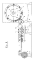
- Nachfolgend soll die Erfindung an einem Ausführungsbeispiel näher erläutert werden. In der beigefügten Zeichnung zeigt:
- Figur 1:
- eine schematische, teilweise geschnittene Ansicht einer erfindungsgemäßen Vorrichtung zur Herstellung einer erfindungsgemäßen Walze und
- Figur 2:
- eine schematische Querschnittsdarstellung eines Teils des durch das aufgewickelte Profilband 1 gebildeten Walzenbelags.
- Die in Figur 1 gezeigte Herstellungsmaschine umfasst einen Ständer 7 zum drehbaren Lagern eines Stahlprofilwickels 2. Von dem Bandwickel 2 wird ein Stahlprofilband 1 zu einem Walzenkern 3 geführt, der ebenfalls auf einem Ständer 8 drehbar gelagert ist und aus Stahl besteht.
- Das Stahlprofilband 1 wird an einem Ende des Walzenkerns 3 umfangsseitig befestigt, beispielsweise angeschweißt. Durch Drehen des Walzenkerns 3 um seine Längsachse 9 und axiales Bewegen des Bandes 1 vom Ende weg wird das Stahlprofilband 1 vom Wickel 2 abgezogen und auf den Walzenkern 3 spiralförmig aufgewickelt. Dabei wird das Stahlprofilband 1 durch mehrere über den Umfang des Walzenkerns verteilt angeordnete Anpressrollen 10 radial auf den Walzenkern 3 gepresst, um die einzelnen Windungen des Stahlprofilbandes 1 fest aneinander anzulegen. Die Anpressrollen 10 sind dabei in einer Halterung gelagert, die durch hier nicht dargestellte Mittel in Axialrichtung des Walzenkerns 3 verschiebbar ist.
- Wie anhand der Figur 2 zu erkennen ist, ist das Profilband 1 derart profiliert, dass es auf seiner einen Vertikalseite einen Vorsprung 11 und auf seiner anderen Vertikalseite eine entsprechende Nut 12 aufweist. Aufeinanderfolgende Windungen des Profilbandes 1 greifen dadurch formschlüssig ineinander. Zudem ist das Profilband 1 an seiner Außenkante 13 mit einem Einschnitt 14 versehen, der im fertigen Walzenbezug eine schraubenförmig verlaufende Rille bildet.
- Zwischen dem Stahlprofilwickel 2 und dem Walzenkern 3 ist eine Einrichtung 6 zum Aufbringen einer Oberflächenstruktur auf das Profilband 1 und eine hier nicht dargestellte Einrichtung zur Beschichtung des Profilbandes 1 mit einer korrosionshemmenden und/oder reibungserhöhenden Schicht angeordnet. Durch die Einrichtung 6 zum Aufbringen einer Oberflächenstruktur kann das Profilband 1 bspw. mit einer durch bspw. Schleifen oder Strahlen, wie bspw. Sandstrahlen, aufgerauten Oberfläche zur Ausbildung der Oberflächenstruktur versehen werden. Beim dargestellten Ausführungsbeispiel handelt es sich im Fall der Einrichtung 6 zur Aufbringung einer Oberflächenstruktur um ein Rändelrad 16 mit Hilfe dessen auf die Oberfläche des Profilbandes 1 eine Oberflächenstruktur aufgerändelt und oder aufgeriffelt wird. Bei der Beschichtungseinrichtung kann es sich bspw. um eine Sprühvorrichtung handeln, mit der das Profilband 1 mit geeignetem Material, beispielsweise einer Chrom-Nickel-Legierung, Wolframcarbid, Zink, Zinn, Lack oder einer Schutzfarbe wie Mennige besprüht werden kann. Alternativ zu der Sprühvorrichtung kann auch ein Tauchbad vorgesehen sein, insbesondere ein galvanisches Bad, ein Bad aus einer Dichtungsmasse oder aus aushärtbarem Kunststoff, durch das Profilband 1 vor dem Aufwickeln auf den Walzenkern 3 hindurchgeführt wird.
- Es können insbesondere auch Mittel zum Aufbringen einer die Oberflächenstruktur bildenden Schicht auf das Strukturband 1 oder neben den Mitteln zum Beschichten des Strukturbandes 1 zusätzlich Mittel zum Einbringen einer Oberflächenstruktur in die erhaltene Schicht vorgesehen sein.
- Die betreffende Einrichtung 6 zum Aufbringen der Oberflächenstruktur kann insbesondere auch Mittel zum Aufbringen einer die Oberflächenstruktur bildenden Folienschicht auf das Strukturband 1 umfassen.
- Mittels der genannten Einrichtung 6 zum Aufbringen der Oberflächenstruktur auf das Profilband 1 kann das vorzugsweise aus Edelstahl bestehende Profilband 1 auf den beiden Seiten, an denen sich die axial aufeinanderfolgenden spiralförmigen Bandwindungen berühren, und/oder auf seiner den Walzenkern 3 berührenden Seite mit einer Oberflächenstruktur versehen werden. Mittels der betreffenden Einrichtung wird das Profilband 1 während des Wickelvorgangs vor dem Auflaufen auf den Walzenkern 3 mit der Oberflächenstruktur versehen. Die betreffende Einrichtung kann insbesondere eine Vorrichtungsstrecke umfassen, durch die das Profilband 1 geführt wird und die das Profilband 1 mit der Oberflächenstruktur versieht.
- Die mittels der betreffenden Einrichtung aufgebrachte Oberflächenstruktur kann insbesondere so gewählt sein, dass sich gegenüber einer nicht strukturierten glatten Bandoberfläche eine Erhöhung des Reibungskoeffizienten um den Faktor 3 bis 4 ergibt.
- Alternativ oder zusätzlich kann auch mit einer auf das Profilband 1 aufgebrachten korrosionshemmenden und/oder reibungserhöhenden Schicht der Reibungskoeffizient gegenüber einer unbeschichteten glatten Bandoberfläche beispielsweise um den Faktor 3 bis 4 erhöht werden. So wird mit der Ummantelung des Profilbandes 1 beispielsweise eine Erhöhung des Reibungskoeffizienten µ von einem Wert im Bereich von 0,16 bis 0,19 auf einem Wert von etwa 0,53 bis etwa 0,7 erreicht werden.
- Mit der Beschichtung wird die Oberflächenrauhigkeit von einem Wert von beispielsweise etwa 0,4 µm auf einen Wert von beispielsweise etwa 0,8 µm erhöht.
- Mit der Vergrößerung der Oberflächenrauhigkeit durch die Oberflächenstruktur bzw. die korrosionshemmende und/oder reibungserhöhende Schicht werden Bewegungen der Bandwindungen relativ zueinander sowie des Profilbandes 1 relativ zum Walzenkern 3 verhindert oder zumindest reduziert.
- Der Stahlprofilwickel 2 kann außerdem um seine Drehachse beschleunigt oder verzögert werden. Hierdurch kann im Profilband 1 eine Eigenspannung eingestellt werden, indem beim Abziehen des Profilbandes 1 vom Wickel 2 durch den rotierenden Walzenkern 3 der Wickel 2 beschleunigt oder verzögert wird. Dabei kann die Eigenspannung an den beiden Enden des Walzenkerns 3 höher oder niedriger eingestellt werden als in der Mitte des Walzenkerns 3. Zudem wird die Eigenspannung bevorzugt so eingestellt, dass sich in der fertigen Walze möglichst keine Relativbewegung zwischen Walzenkern 3 und aufgewickeltem Profilband 1 ergibt.
- Des Weiteren sind zur Regelung der Eigenspannung des Profilbandes 1 Messrollen 15 vorgesehen, die direkt oder indirekt die Eigenspannung des Profilbandes messen und die Messwerte an eine nicht dargestellte Regelungseinrichtung übergeben.
- Außerdem ist gemäß Figur 1 eine Antriebs- und Bremseinrichtung 4 zwischen dem Stahlprofilwickel 2 und dem Walzenkern 3 angeordnet. Die Antriebs- und Bremseinrichtung 4 umfasst zwei Walzenpaare 5, zwischen denen das Profilband 1 unter Reibung hindurchgeführt ist. Durch Abbremsen oder Beschleunigen der Walzenpaare 5 kann die Eigenspannung oder innere Spannung des Profilbandes 1 in gewünschter Weise eingestellt werden, was über eine Messrolle 15 und geeignete Regelungsmittel einer Regelung der Eigen- bzw. Innenspannung ermöglicht.
- Die Eigenspannung des Bandes 1 wird dabei auf Werte von über 600 MPa eingestellt. Eine derart hohe Spannung übersteigt die Elastizitätsgrenze des Walzenkerns 3 an der Manteloberfläche, so dass das Band 1 in die Manteloberfläche eindringt und dort ein plastische Verformung hervorruft. Dies führt zur Bildung von Rillen in der Manteloberfläche, die einen Teil des Profilbandes 1 umschließen und so durch den Formschluss zwischen Band 1 und Walzenkern 3 die Lage der Bandwindungen stabilisieren.
- Das radiale Anpressen des Bandes 1 über die Anpressrollen 10 kann das Eindringen des Profilbandes 1 in den Walzenkern 3 noch in erheblichem Umfang unterstützen.
- Vor der Antriebs- und Bremseinrichtung 4 befindet sich noch eine Richtvorrichtung 17, welche das Profilband 1 während des Durchlaufens gerade Ausrichten soll.
- Bei der erfindungsgemäßen Vorrichtung bzw. der erfindungsgemäßen Walze ergeben sich außerdem eine verringerte Korrosionsgefahr sowie verringerte Relativbewegung zwischen den einzelnen Windungen des Profilbandes 1 bzw. zwischen dem Profilband 1 und dem Walzenkern 3. Die Haltbarkeit der erfindungsgemäßen Walze ist dadurch gegenüber bekannten Walzen erhöht.
-
- 1
- Stahlprofilband
- 2
- Bandwickel
- 3
- Walzenkern
- 4
- Antriebs- und Bremseinrichtung
- 5
- Walzenpaar
- 6
- Einrichtung
- 7,8
- Ständer
- 9
- Längsachse
- 10
- Anpressrollen
- 11
- Vorsprung
- 12
- Nut
- 13
- Außenkante
- 14
- Einschnitt
- 15
- Messrollen
- 16
- Rändelrad
- 17
- Richtvorrichtung
Claims (20)
- Verfahren zur Herstellung einer Walze für eine Machine zur Herstellung und/oder Veredlung einer Papier-, Karton-, Tissue- oder einer anderen Faserstoffbahn, bei dem ein profiliertes Band (1) spiralförmig um einen mantelförmigen Walzenkern (3) gewickelt wird, dadurch gekennzeichnet, dass
beim Aufwickeln des Bandes (1) dessen Eigenspannung so hoch eingestellt oder geregelt wird, dass die Elastizitätsgrenze der Manteloberfläche des Walzenkerns (3) überschritten wird. - Verfahren nach Anspruch 1, dadurch gekennzeichnet, dass
die Eigenspannung des Bandes (1) auf Werte von mehr als 600 MPa eingestellt wird. - Verfahren nach einem der vorhergehenden Ansprüche, dadurch gekennzeichnet, dass
im Bereich der Walzenenden eine höhere oder niedrigere Eigenspannung des Bandes (1) eingestellt wird als im Bereich der Walzenmitte. - Verfahren nach einem der vorhergehenden Ansprüche, dadurch gekennzeichnet, dass
die Eigenspannung durch Beschleunigen oder Verzögern des Bandes (1) beim Aufwickeln eingestellt wird. - Verfahren nach einem der vorhergehenden Ansprüche, dadurch gekennzeichnet, dass
das Band (1) durch Drehen des Walzenkerns (3) aufgewickelt wird und dass das Beschleunigen oder Verzögern des Bandes (1) durch zusätzlich auf das Band (1) einwirkende Antriebs- und Bremsmittel bewirkt wird. - Verfahren nach Anspruch 4 oder 5, dadurch gekennzeichnet, dass
zum Beschleunigen oder Verzögern des Bandes (1) zwei einander gegenüberliegende, angetriebene Beschleunigungs-/Verzögerungsstrecken (4) eingesetzt werden und das Band (1) zwischen diesen hindurchgeführt wird. - Verfahren nach einem der Ansprüche 4 bis 6, dadurch gekennzeichnet, dass das Beschleunigen oder Verzögern des Bandes (1) durch Beschleunigen bzw. Verzögern mindestens eines Walzenpaares (5) erfolgt, durch welches das Band (1) unter Reibung hindurchgeführt wird.
- Verfahren nach einem der 4 bis 7, dadurch gekennzeichnet, dass
das Beschleunigen oder Verzögern des Bandes (1) durch Beschleunigen bzw. Verzögern eines Wickels (2) erfolgt, von dem das Band (1) abgezogen wird. - Verfahren nach Anspruch 8, dadurch gekennzeichnet, dass
der Wickel (2), von dem das Band (1) abgezogen wird, mittels eines geregelten Motors entsprechend beschleunigt oder verzögert wird, um das Band (1) mit einer insbesondere konstanten, geregelten Zugspannung zu beaufschlagen. - Verfahren nach einem der vorhergehenden Ansprüche, dadurch gekennzeichnet, dass
die Eigenspannung des Bandes (1) während des Aufwickelns gemessen und der festgestellte Wert für eine Regelung der Eigenspannung verwendet wird. - Verfahren nach einem der vorhergehenden Ansprüche, dadurch gekennzeichnet, dass
das Band (1) beim Aufwickeln an wenigstens einer Stelle radial auf den Walzenkern (3) gepresst wird. - Verfahren nach einem der vorhergehenden Ansprüche, dadurch gekennzeichnet, dass
als Band (1) ein Stahlband, insbesondere Edelstahlband, verwendet wird. - Verfahren nach einem der vorhergehenden Ansprüche, dadurch gekennzeichnet, dass
das Band (1) vor dem Aufwickeln mit einer korrosionshemmenden und/oder reibungserhöhenden Schicht versehen wird. - Verfahren nach Anspruch 13, dadurch gekennzeichnet, dass
das Band während des Wickelvorgangs vor dem Auflaufen auf den Walzenkern (3) durch eine Vorrichtungsstrecke (6) geführt wird, die das Band (1) mit der Schicht versieht. - Verfahren nach Anspruch 13 oder 14, dadurch gekennzeichnet, dass
das Band (1) mit einer solchen Schicht versehen wird, dass sich ein gegenüber einer unbeschichteten glatten Bandoberfläche um den Faktor 3 bis 4 erhöhter Reibungskoeffizient einstellt. - Verfahren nach einem der Ansprüche 13 bis 15, dadurch gekennzeichnet, dass
eine Chrom-Nickel-Legierung, Wolframcarbid, Zink, Zinn, Lack und/oder eine Schutzfarbe wie Mennige für die korrosionshemmende Schicht verwendet wird. - Walze für eine Machine zur Herstellung und/oder Veredlung einer Papier-, Karton-, Tissue- oder einer anderen Faserstoffbahn, mit einem mantelförmigen Walzenkern (3) und einem spiralförmig um den Walzenkern (3) gewickelten, profilierten Band (1), insbesondere hergestellt gemäß einem Verfahren nach einem der vorhergehenden Ansprüche, dadurch gekennzeichnet, dass das Band (1) teilweise in den Walzenkern (3) eingebettet ist.
- Walze nach Anspruch 17, dadurch gekennzeichnet, dass
der Walzenkern (3) oder dessen Bezug aus Gusseisen oder Stahl besteht. - Walze nach Anspruch 17 oder 18, dadurch gekennzeichnet, dass
das Band (1) aus Stahl, insbesondere Edelstahl besteht. - Walze nach einem der Ansprüche 17 bis 19, dadurch gekennzeichnet, dass das Band (1) um 0 bis 0,5 mm in den Walzenkern (3) gedrückt ist.
Applications Claiming Priority (1)
| Application Number | Priority Date | Filing Date | Title |
|---|---|---|---|
| DE102006032866A DE102006032866A1 (de) | 2006-07-14 | 2006-07-14 | Walzenbezug |
Publications (2)
| Publication Number | Publication Date |
|---|---|
| EP1878828A1 true EP1878828A1 (de) | 2008-01-16 |
| EP1878828B1 EP1878828B1 (de) | 2011-02-23 |
Family
ID=38627006
Family Applications (1)
| Application Number | Title | Priority Date | Filing Date |
|---|---|---|---|
| EP07105069A Not-in-force EP1878828B1 (de) | 2006-07-14 | 2007-03-28 | Walze und Verfahren zu deren Herstellung |
Country Status (3)
| Country | Link |
|---|---|
| EP (1) | EP1878828B1 (de) |
| AT (1) | ATE499484T1 (de) |
| DE (2) | DE102006032866A1 (de) |
Families Citing this family (1)
| Publication number | Priority date | Publication date | Assignee | Title |
|---|---|---|---|---|
| CN110924218B (zh) * | 2019-12-31 | 2021-08-10 | 贵州金马包装材料有限公司 | 一种彩卡纸的压光装置 |
Citations (3)
| Publication number | Priority date | Publication date | Assignee | Title |
|---|---|---|---|---|
| DE2545146A1 (de) | 1974-10-09 | 1976-04-29 | Valmet Oy | Verfahren zum herstellen des gerillten belags einer papiermaschinenwalze durch wickeln von profilband |
| DE2913362A1 (de) | 1978-04-03 | 1979-10-18 | Stroemungsmasch Anst | Verfahren zur herstellung von rillenwalzen fuer die entwaesserung einer materialbahn sowie profildraht- und walzenmantelausbildung zur durchfuehrung des verfahrens |
| DE3050682C1 (de) * | 1980-12-24 | 1987-07-16 | Chismatulin Enver Rachmatullov | Einrichtung zum mehrfach-wendelfoermigen Aufwickeln von Stahlband zu Mehrlagenrohren |
-
2006
- 2006-07-14 DE DE102006032866A patent/DE102006032866A1/de not_active Withdrawn
-
2007
- 2007-03-28 EP EP07105069A patent/EP1878828B1/de not_active Not-in-force
- 2007-03-28 AT AT07105069T patent/ATE499484T1/de active
- 2007-03-28 DE DE502007006531T patent/DE502007006531D1/de active Active
Patent Citations (3)
| Publication number | Priority date | Publication date | Assignee | Title |
|---|---|---|---|---|
| DE2545146A1 (de) | 1974-10-09 | 1976-04-29 | Valmet Oy | Verfahren zum herstellen des gerillten belags einer papiermaschinenwalze durch wickeln von profilband |
| DE2913362A1 (de) | 1978-04-03 | 1979-10-18 | Stroemungsmasch Anst | Verfahren zur herstellung von rillenwalzen fuer die entwaesserung einer materialbahn sowie profildraht- und walzenmantelausbildung zur durchfuehrung des verfahrens |
| DE3050682C1 (de) * | 1980-12-24 | 1987-07-16 | Chismatulin Enver Rachmatullov | Einrichtung zum mehrfach-wendelfoermigen Aufwickeln von Stahlband zu Mehrlagenrohren |
Also Published As
| Publication number | Publication date |
|---|---|
| DE502007006531D1 (de) | 2011-04-07 |
| ATE499484T1 (de) | 2011-03-15 |
| EP1878828B1 (de) | 2011-02-23 |
| DE102006032866A1 (de) | 2008-01-17 |
Similar Documents
| Publication | Publication Date | Title |
|---|---|---|
| EP0603841B1 (de) | Verfahren und Vorrichtung zum Aufwickeln von Rundmaterial auf eine mit Endflanschen versehene Spule | |
| DE3521485C2 (de) | Vorrichtung zur Herstellung eines verseilten, mehrdrähtigen, verdichteten Rundleiters | |
| DE3050507C1 (de) | Vorrichtung zum horizontalen Abziehen von Strangmaterial | |
| EP1824618B1 (de) | Verfahren zur abbremsung eines laufenden metallbandes und anlage zur durchführung des verfahrens | |
| EP1136616B1 (de) | Verfahren und Vorrichtung zur Vorformung von Stahldrähten | |
| EP1878828B1 (de) | Walze und Verfahren zu deren Herstellung | |
| DE3308283C2 (de) | Vorrichtung und Verfahren zum Aufwickeln von Kabeln oder biegsamen Leitungen auf Trommeln und ein Verfahren zum Justieren der Vorrichtung von Beginn des Wickelvorganges | |
| DE102017222107B4 (de) | Verfahren sowie Vorrichtung zur Herstellung einer Leitung | |
| EP0626479B1 (de) | Streicheinrichtung zur Beschichtung laufender Stoffbahnen | |
| EP1274104A1 (de) | Verfahren zum Bewickeln eines Dreiphasen-Kabeltransformators mit Koaxialkabel und Wickelvorrichtung hierzu | |
| EP1700951B1 (de) | Verfahren und Vorrichtung zur Herstellung einer Walze für eine Papiermaschine sowie derartige Walze | |
| WO1995012023A1 (de) | Verfahren und vorrichtung zur herstellung von stahlcord | |
| DE10130469B4 (de) | Verfahren und Bandbehandlungsanlage, insbesondere Bandwalzstraße oder Bandwalzgerüst zum Vermeiden von Bandklebern beim Haspeln | |
| EP1410857B1 (de) | Verfahren zur Herstellung ringförmiger Blechpakete für vielpolige elektrische Maschinen | |
| EP0438674A2 (de) | Verfahren zum gleichzeitigen Aufwickeln mehrerer Spaltbänder aus Metall | |
| DE2714669C3 (de) | Verfahren zum Herstellen eines Belags für eine Walze | |
| EP2669228B1 (de) | Gewickelte Drahtspule sowie Vorrichtung und Verfahren zur Herstellung der Drahtspule | |
| EP1929078B1 (de) | Fadenabzugsrolle für eine kreuzspulen herstellende textilmaschine | |
| DE102005040447A1 (de) | Walzenbezug | |
| DE3315910C2 (de) | ||
| DE2941160A1 (de) | An seiner innenflaeche auf verschleiss beanspruchter metallischer, zylindrischer hohlkoerper | |
| DE2540814C3 (de) | Ziehtrommel mit Vorratstrommel | |
| DE937182C (de) | Verfahren und Vorrichtung zur Herstellung schraubenfoermiger Wicklungen aus einem hochkant gegen die Wickelachse stehenden Metallband | |
| DE3810532A1 (de) | Verfahren und vorrichtung zum aufwickeln von strangfoermigem gut | |
| DE19811209C2 (de) | Verfahren und Vorrichtung zum Richten von Draht |
Legal Events
| Date | Code | Title | Description |
|---|---|---|---|
| PUAI | Public reference made under article 153(3) epc to a published international application that has entered the european phase |
Free format text: ORIGINAL CODE: 0009012 |
|
| AK | Designated contracting states |
Kind code of ref document: A1 Designated state(s): AT BE BG CH CY CZ DE DK EE ES FI FR GB GR HU IE IS IT LI LT LU LV MC MT NL PL PT RO SE SI SK TR |
|
| AX | Request for extension of the european patent |
Extension state: AL BA HR MK YU |
|
| 17P | Request for examination filed |
Effective date: 20080716 |
|
| 17Q | First examination report despatched |
Effective date: 20080814 |
|
| AKX | Designation fees paid |
Designated state(s): AT BE BG CH CY CZ DE DK EE ES FI FR GB GR HU IE IS IT LI LT LU LV MC MT NL PL PT RO SE SI SK TR |
|
| GRAP | Despatch of communication of intention to grant a patent |
Free format text: ORIGINAL CODE: EPIDOSNIGR1 |
|
| GRAS | Grant fee paid |
Free format text: ORIGINAL CODE: EPIDOSNIGR3 |
|
| GRAA | (expected) grant |
Free format text: ORIGINAL CODE: 0009210 |
|
| AK | Designated contracting states |
Kind code of ref document: B1 Designated state(s): AT BE BG CH CY CZ DE DK EE ES FI FR GB GR HU IE IS IT LI LT LU LV MC MT NL PL PT RO SE SI SK TR |
|
| REG | Reference to a national code |
Ref country code: GB Ref legal event code: FG4D Free format text: NOT ENGLISH |
|
| REG | Reference to a national code |
Ref country code: CH Ref legal event code: EP |
|
| REG | Reference to a national code |
Ref country code: IE Ref legal event code: FG4D Free format text: LANGUAGE OF EP DOCUMENT: GERMAN |
|
| REF | Corresponds to: |
Ref document number: 502007006531 Country of ref document: DE Date of ref document: 20110407 Kind code of ref document: P |
|
| REG | Reference to a national code |
Ref country code: DE Ref legal event code: R096 Ref document number: 502007006531 Country of ref document: DE Effective date: 20110407 |
|
| REG | Reference to a national code |
Ref country code: NL Ref legal event code: VDEP Effective date: 20110223 |
|
| LTIE | Lt: invalidation of european patent or patent extension |
Effective date: 20110223 |
|
| PG25 | Lapsed in a contracting state [announced via postgrant information from national office to epo] |
Ref country code: LV Free format text: LAPSE BECAUSE OF FAILURE TO SUBMIT A TRANSLATION OF THE DESCRIPTION OR TO PAY THE FEE WITHIN THE PRESCRIBED TIME-LIMIT Effective date: 20110223 Ref country code: GR Free format text: LAPSE BECAUSE OF FAILURE TO SUBMIT A TRANSLATION OF THE DESCRIPTION OR TO PAY THE FEE WITHIN THE PRESCRIBED TIME-LIMIT Effective date: 20110524 Ref country code: SE Free format text: LAPSE BECAUSE OF FAILURE TO SUBMIT A TRANSLATION OF THE DESCRIPTION OR TO PAY THE FEE WITHIN THE PRESCRIBED TIME-LIMIT Effective date: 20110223 Ref country code: LT Free format text: LAPSE BECAUSE OF FAILURE TO SUBMIT A TRANSLATION OF THE DESCRIPTION OR TO PAY THE FEE WITHIN THE PRESCRIBED TIME-LIMIT Effective date: 20110223 Ref country code: PT Free format text: LAPSE BECAUSE OF FAILURE TO SUBMIT A TRANSLATION OF THE DESCRIPTION OR TO PAY THE FEE WITHIN THE PRESCRIBED TIME-LIMIT Effective date: 20110623 Ref country code: ES Free format text: LAPSE BECAUSE OF FAILURE TO SUBMIT A TRANSLATION OF THE DESCRIPTION OR TO PAY THE FEE WITHIN THE PRESCRIBED TIME-LIMIT Effective date: 20110603 |
|
| PG25 | Lapsed in a contracting state [announced via postgrant information from national office to epo] |
Ref country code: CY Free format text: LAPSE BECAUSE OF FAILURE TO SUBMIT A TRANSLATION OF THE DESCRIPTION OR TO PAY THE FEE WITHIN THE PRESCRIBED TIME-LIMIT Effective date: 20110223 Ref country code: SI Free format text: LAPSE BECAUSE OF FAILURE TO SUBMIT A TRANSLATION OF THE DESCRIPTION OR TO PAY THE FEE WITHIN THE PRESCRIBED TIME-LIMIT Effective date: 20110223 Ref country code: NL Free format text: LAPSE BECAUSE OF FAILURE TO SUBMIT A TRANSLATION OF THE DESCRIPTION OR TO PAY THE FEE WITHIN THE PRESCRIBED TIME-LIMIT Effective date: 20110223 Ref country code: BG Free format text: LAPSE BECAUSE OF FAILURE TO SUBMIT A TRANSLATION OF THE DESCRIPTION OR TO PAY THE FEE WITHIN THE PRESCRIBED TIME-LIMIT Effective date: 20110523 |
|
| REG | Reference to a national code |
Ref country code: IE Ref legal event code: FD4D |
|
| BERE | Be: lapsed |
Owner name: VOITH PATENT G.M.B.H. Effective date: 20110331 |
|
| PG25 | Lapsed in a contracting state [announced via postgrant information from national office to epo] |
Ref country code: DK Free format text: LAPSE BECAUSE OF FAILURE TO SUBMIT A TRANSLATION OF THE DESCRIPTION OR TO PAY THE FEE WITHIN THE PRESCRIBED TIME-LIMIT Effective date: 20110223 Ref country code: MC Free format text: LAPSE BECAUSE OF NON-PAYMENT OF DUE FEES Effective date: 20110331 Ref country code: EE Free format text: LAPSE BECAUSE OF FAILURE TO SUBMIT A TRANSLATION OF THE DESCRIPTION OR TO PAY THE FEE WITHIN THE PRESCRIBED TIME-LIMIT Effective date: 20110223 Ref country code: IE Free format text: LAPSE BECAUSE OF FAILURE TO SUBMIT A TRANSLATION OF THE DESCRIPTION OR TO PAY THE FEE WITHIN THE PRESCRIBED TIME-LIMIT Effective date: 20110223 |
|
| REG | Reference to a national code |
Ref country code: CH Ref legal event code: PL |
|
| PG25 | Lapsed in a contracting state [announced via postgrant information from national office to epo] |
Ref country code: RO Free format text: LAPSE BECAUSE OF FAILURE TO SUBMIT A TRANSLATION OF THE DESCRIPTION OR TO PAY THE FEE WITHIN THE PRESCRIBED TIME-LIMIT Effective date: 20110223 Ref country code: SK Free format text: LAPSE BECAUSE OF FAILURE TO SUBMIT A TRANSLATION OF THE DESCRIPTION OR TO PAY THE FEE WITHIN THE PRESCRIBED TIME-LIMIT Effective date: 20110223 Ref country code: CZ Free format text: LAPSE BECAUSE OF FAILURE TO SUBMIT A TRANSLATION OF THE DESCRIPTION OR TO PAY THE FEE WITHIN THE PRESCRIBED TIME-LIMIT Effective date: 20110223 |
|
| PG25 | Lapsed in a contracting state [announced via postgrant information from national office to epo] |
Ref country code: BE Free format text: LAPSE BECAUSE OF NON-PAYMENT OF DUE FEES Effective date: 20110331 Ref country code: MT Free format text: LAPSE BECAUSE OF FAILURE TO SUBMIT A TRANSLATION OF THE DESCRIPTION OR TO PAY THE FEE WITHIN THE PRESCRIBED TIME-LIMIT Effective date: 20110223 |
|
| PLBE | No opposition filed within time limit |
Free format text: ORIGINAL CODE: 0009261 |
|
| STAA | Information on the status of an ep patent application or granted ep patent |
Free format text: STATUS: NO OPPOSITION FILED WITHIN TIME LIMIT |
|
| GBPC | Gb: european patent ceased through non-payment of renewal fee |
Effective date: 20110523 |
|
| PG25 | Lapsed in a contracting state [announced via postgrant information from national office to epo] |
Ref country code: CH Free format text: LAPSE BECAUSE OF NON-PAYMENT OF DUE FEES Effective date: 20110331 Ref country code: LI Free format text: LAPSE BECAUSE OF NON-PAYMENT OF DUE FEES Effective date: 20110331 |
|
| 26N | No opposition filed |
Effective date: 20111124 |
|
| PG25 | Lapsed in a contracting state [announced via postgrant information from national office to epo] |
Ref country code: PL Free format text: LAPSE BECAUSE OF FAILURE TO SUBMIT A TRANSLATION OF THE DESCRIPTION OR TO PAY THE FEE WITHIN THE PRESCRIBED TIME-LIMIT Effective date: 20110223 |
|
| REG | Reference to a national code |
Ref country code: FR Ref legal event code: ST Effective date: 20120210 |
|
| REG | Reference to a national code |
Ref country code: DE Ref legal event code: R097 Ref document number: 502007006531 Country of ref document: DE Effective date: 20111124 |
|
| PG25 | Lapsed in a contracting state [announced via postgrant information from national office to epo] |
Ref country code: FR Free format text: LAPSE BECAUSE OF NON-PAYMENT OF DUE FEES Effective date: 20110426 |
|
| PG25 | Lapsed in a contracting state [announced via postgrant information from national office to epo] |
Ref country code: IT Free format text: LAPSE BECAUSE OF FAILURE TO SUBMIT A TRANSLATION OF THE DESCRIPTION OR TO PAY THE FEE WITHIN THE PRESCRIBED TIME-LIMIT Effective date: 20110223 |
|
| PGFP | Annual fee paid to national office [announced via postgrant information from national office to epo] |
Ref country code: DE Payment date: 20120323 Year of fee payment: 6 |
|
| PG25 | Lapsed in a contracting state [announced via postgrant information from national office to epo] |
Ref country code: GB Free format text: LAPSE BECAUSE OF NON-PAYMENT OF DUE FEES Effective date: 20110523 |
|
| PGFP | Annual fee paid to national office [announced via postgrant information from national office to epo] |
Ref country code: FI Payment date: 20120313 Year of fee payment: 6 |
|
| PGFP | Annual fee paid to national office [announced via postgrant information from national office to epo] |
Ref country code: AT Payment date: 20120313 Year of fee payment: 6 |
|
| PG25 | Lapsed in a contracting state [announced via postgrant information from national office to epo] |
Ref country code: LU Free format text: LAPSE BECAUSE OF NON-PAYMENT OF DUE FEES Effective date: 20110328 |
|
| PG25 | Lapsed in a contracting state [announced via postgrant information from national office to epo] |
Ref country code: IS Free format text: LAPSE BECAUSE OF FAILURE TO SUBMIT A TRANSLATION OF THE DESCRIPTION OR TO PAY THE FEE WITHIN THE PRESCRIBED TIME-LIMIT Effective date: 20110223 |
|
| PG25 | Lapsed in a contracting state [announced via postgrant information from national office to epo] |
Ref country code: TR Free format text: LAPSE BECAUSE OF FAILURE TO SUBMIT A TRANSLATION OF THE DESCRIPTION OR TO PAY THE FEE WITHIN THE PRESCRIBED TIME-LIMIT Effective date: 20110223 |
|
| PG25 | Lapsed in a contracting state [announced via postgrant information from national office to epo] |
Ref country code: HU Free format text: LAPSE BECAUSE OF FAILURE TO SUBMIT A TRANSLATION OF THE DESCRIPTION OR TO PAY THE FEE WITHIN THE PRESCRIBED TIME-LIMIT Effective date: 20110223 Ref country code: FI Free format text: LAPSE BECAUSE OF NON-PAYMENT OF DUE FEES Effective date: 20130328 |
|
| REG | Reference to a national code |
Ref country code: AT Ref legal event code: MM01 Ref document number: 499484 Country of ref document: AT Kind code of ref document: T Effective date: 20130328 |
|
| REG | Reference to a national code |
Ref country code: DE Ref legal event code: R119 Ref document number: 502007006531 Country of ref document: DE Effective date: 20131001 |
|
| PG25 | Lapsed in a contracting state [announced via postgrant information from national office to epo] |
Ref country code: AT Free format text: LAPSE BECAUSE OF NON-PAYMENT OF DUE FEES Effective date: 20130328 Ref country code: DE Free format text: LAPSE BECAUSE OF NON-PAYMENT OF DUE FEES Effective date: 20131001 |