EP1878367A1 - Ustensile de cuisine avec rebord renforcé - Google Patents
Ustensile de cuisine avec rebord renforcé Download PDFInfo
- Publication number
- EP1878367A1 EP1878367A1 EP07013149A EP07013149A EP1878367A1 EP 1878367 A1 EP1878367 A1 EP 1878367A1 EP 07013149 A EP07013149 A EP 07013149A EP 07013149 A EP07013149 A EP 07013149A EP 1878367 A1 EP1878367 A1 EP 1878367A1
- Authority
- EP
- European Patent Office
- Prior art keywords
- article
- cookware
- layer
- rim
- metal
- Prior art date
- Legal status (The legal status is an assumption and is not a legal conclusion. Google has not performed a legal analysis and makes no representation as to the accuracy of the status listed.)
- Withdrawn
Links
Images


Classifications
-
- A—HUMAN NECESSITIES
- A47—FURNITURE; DOMESTIC ARTICLES OR APPLIANCES; COFFEE MILLS; SPICE MILLS; SUCTION CLEANERS IN GENERAL
- A47J—KITCHEN EQUIPMENT; COFFEE MILLS; SPICE MILLS; APPARATUS FOR MAKING BEVERAGES
- A47J27/00—Cooking-vessels
- A47J27/002—Construction of cooking-vessels; Methods or processes of manufacturing specially adapted for cooking-vessels
-
- B—PERFORMING OPERATIONS; TRANSPORTING
- B23—MACHINE TOOLS; METAL-WORKING NOT OTHERWISE PROVIDED FOR
- B23K—SOLDERING OR UNSOLDERING; WELDING; CLADDING OR PLATING BY SOLDERING OR WELDING; CUTTING BY APPLYING HEAT LOCALLY, e.g. FLAME CUTTING; WORKING BY LASER BEAM
- B23K26/00—Working by laser beam, e.g. welding, cutting or boring
- B23K26/20—Bonding
- B23K26/21—Bonding by welding
- B23K26/24—Seam welding
- B23K26/28—Seam welding of curved planar seams
-
- B—PERFORMING OPERATIONS; TRANSPORTING
- B23—MACHINE TOOLS; METAL-WORKING NOT OTHERWISE PROVIDED FOR
- B23K—SOLDERING OR UNSOLDERING; WELDING; CLADDING OR PLATING BY SOLDERING OR WELDING; CUTTING BY APPLYING HEAT LOCALLY, e.g. FLAME CUTTING; WORKING BY LASER BEAM
- B23K9/00—Arc welding or cutting
- B23K9/0026—Arc welding or cutting specially adapted for particular articles or work
Definitions
- the present invention relates to improved cookware vessels, and in particular generally circular shaped pots and pans.
- Multi-ply and laminated cookware vessels such as pots and pans, are well known in the art. They typically deploy copper and/or aluminum as one or more core layers, with surrounding layers to form the exposed interior and/or exterior surface of the cookware.
- the copper and/or aluminum core layers enhance the thermal performance of the cookware; enabling both a faster heating of the foodstuffs and a more uniform temperature distribution.
- Outer layers of the laminate, that surrounds the copper and/or aluminum core, can provide an exterior surface that is easier to clean or maintain a particularly desired appearance in the kitchen.
- Such laminated articles of cookware are fabricated starting with pre-laminated sheet stock.
- Methods of making sheet stock suitable for eventually forming cookware are disclosed in U.S. Patent 6,427,904 to Groll , titled “Bonding of Dissimilar Metals", as well as U.S. Patent 6,109,504 , also to Groll, and titled “Copper Core Cooking Griddle and Method of Making Same”.
- the '504 patent teaches the desirability of forming a sheet stock laminate of stainless steel/copper/stainless steel useful for fabricating cookware via the sequential reduction of thickness by repeated hot roll bonding steps.
- the preferred compositions in the construction is a diffusion bonded composite of 304L grade stainless steel outer layers with an inner core of high purity C-102 grade copper. However, explosion bonding is initially used to laminate the three layers.
- the cookware is then fabricated from the laminated sheet stock by first cutting or trimming the sheet stock into round shape.
- the round trimmed pieces are then deformed or drawn in a die to form a fluid containing cookware vessel.
- the trimming process whether done at the beginning or end of the drawing process, exposes all the layers in the cookware article.
- the softer copper or aluminum used in the core of the laminate, along with the stainless steel outer cladding layer are exposed at the rim.
- the core materials at the rim being softer and exposed at the rim are susceptible to denting or damage.
- the strength of the rim is a factor in the selection of the laminating material used to form the cookware article. That is, but for the softer materials exposed at the rim and the need to make the rim strong to resist deformation, the article of cookware could be made of thinner laminates, thus reducing weight as well as saving on material cost.
- a clad article of cookware that comprises a substantially circular bottom having an interior cooking surface formed of a first metallic layer, substantially vertical walls surrounding said bottom to form a vessel capable of retaining fluid, said vertical walls terminating at a rim, wherein the interior surface of said vertical walls are contiguous with said interior cooking surface being formed of the first metallic layer, and at least a portion of the exterior surface of said vertical walls are formed of a second metal, and further wherein a portion of the first metal extends beyond the rim and extends down at least a portion of the exterior surface of said vertical walls whereby the second metal is not exposed at the rim.
- Another aspect of the invention is characterized by a process for forming an article of cookware that includes forming a proto-vessel having an interior metal layer and an exterior metal layer, the exterior metal layer terminating at a first rim below the height of the interior metal layer that defines a second rim, and then folding the portion of the interior metal layer that exceeds the height of the first rim whereby such portion of the interior layer forms the interior and exterior layer of the cooking vessel at the rim thereof.
- the above aspects of the invention provide the advantages that one of the two or more clad or laminated layers are protected at the rim from denting and related physical or chemical degradation.
- a further advantage is achieved by using a stronger material, such as stainless steel or titanium, for the inner layer to reinforce a thinner or softer middle or outer layer, allowing a reduction in the weight of the pan, as well as a thicker bottom layer for superior heat transfer to the foodstuffs and thermal uniformity.
- a stronger material such as stainless steel or titanium
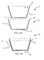
- Figures 1A and 1B are cross-sectional elevations of the initial steps in forming the article of cookware.
- Figures 2A and 2B are cross-sectional elevations illustrating the steps of forming the rim of the article of cookware.
- Figure 3 is a cross-sectional elevation of the finished cookware vessel, prior to the addition of a side handle.
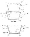
- Figures 4A and 4B are cross-sectional elevations of the initial steps in forming the article of cookware according to an alternative embodiment of the invention.
- Figures 5A and 5B are cross-sectional elevations illustrating the steps of forming the rim of the article of cookware in the embodiment illustrated in Figure 4.
- Figure 6 is a cross-sectional elevation of the alternative embodiment of the cookware article, prior to the addition of a side handle, as resulting from the processes shown in Figures 4 and 5.
- Figures 1-2 illustrate a sequence of steps in forming the article of cookware 100
- Figure 3 is a cross sectional elevation of the completed article of cookware, ready for the attachment of one or more side handles.
- the completed article of cookware 100 has a bottom 32 surrounded by substantially upright sidewalls 31 to form a fluid containing vessel 100, which terminates at rim 33.
- the upright side 31 has an inner layer 10' formed from an inner vessel 10 that is nested inside an outer vessel 20 (as shown in Figure 1B).
- sidewall 31 has an outer layer 20' formed from the side wall of outer vessel 20.
- rim 33 is formed by the upper end 14 of the sidewall 11 of inner vessel 10 that extends above the rim 23 of the outer vessel 20. As shown in Figures 2B and 3, this upper end 14 is bent or drawn over rim 23 such that a portion 15 extends downward from the rim 33 covering a portion of outer sidewall 20'.
- a fluid containing inner vessel 10 having a bottom 12 is surrounded by substantially upright sidewalls 11 which terminates at rim 13 is nested inside a slightly larger outer vessel 20.
- the generally fluid containing outer vessel 20 has a bottom 22 and is surrounded by a substantially upright sidewall 21 that terminates in rim 23.
- the inner 10 and outer vessel 20 are bonded to form proto-vessel 30, shown in Figure 2B. It should be noted that a portion 14 of the upright wall 11 of inner vessel now extends above the rim 23 of outer vessel 20.
- bottom portion 32 is formed from bottom 12 and 22 of the inner vessel 10 and the outer vessel 20 respectively.
- sidewall 31 is formed from sidewalls 11 and 21 of the inner vessel 10 and the outer vessel 20 respectively.
- the inner vessel 10 is preferably formed from stainless steel or titanium.
- the outer vessel 20 is preferable formed of aluminum. It should be further appreciated that the outer vessel 20 is alternatively copper.
- the bonding of the inner vessel 10 and outer vessel 20 employs at least one of the steps of impact bonding and/or brazing. If brazing is used to bond the inner vessel 10 and outer vessel 20, then a brazing compound is applied to at least one of the exterior of the inner vessel 10 or the interior of the outer vessel 20 prior to the nesting.
- the temperature of the proto-vessel 31 is raised to melt the brazing compound, which upon cooling forms a metallurgical bond at interface 112, uniting the inner vessel 10 and outer vessel 20.
- Pressure is applied to compress the inner vessel 10 and outer vessel 20 against each other at the common interface 112, facilitating the consolidation and flow of the liquid brazing compound.
- each of the inner vessel 10 and outer vessel 20 are drawn in with sufficient dimension tolerances to facilitate the nested insertion to form unbounded proto-vessel 30. It is also preferable that a slight gap be present after nesting to accommodate the solid brazing compound (as well as for the eventual wicking of the molten brazing compound or liquid flux) at the common interface 112, of pro to-vessel 30.
- an "ironing process” be used after brazing or impact bonding. “Ironing” is done by the repetitive steps of deep drawing of proto-vessel 30 in a set of dies with the clearance between male and female die members that are progressively smaller than the actual combined thicknesses of the sidewall 31.
- the thickness of layer 21 is generally reduced. As it can be difficult in the brazing process to fully reflow the liquid flux over the entire areas to be bonded in interface 112, air and moisture can be trapped within this gap.
- the "ironing process” is also advantageous as it gradually expels air and moisture trapped at the common interface 112. For example, when the outer layer 11 is stainless steel layer, it will remain substantially the same height as in inner vessel 10. However, as the wall thickness of a softer outer layer 21, such as aluminum or copper, will be reduced, the height of this wall will increase as this material is pushed upward during the ironing process. Thus, the final position of the rim of the outer vessel in proto-vessel 30 is shown in Figures 2A as 23'.
- Figures 2A-2B illustrate the next step in the inventive process in which the portion 14 of sidewall 11 is rolled over rim 23' to form the final rim 33 of the completed vessel 100.
- the direction of bending and rolling rim portion 14 is shown by arrow 61, with phantom portions 62 and 63, in broken lines, to show the progressive movement of portion 14 until the rolling process is completed ( Figure 2B).
- FIG. 2 Another preferred aspect of the fabrication process, illustrated in Figure 2, is to fabricate a groove 24 along the circumference of the outer vessel 20 below the rim 23'.
- the edge 25 of the rim forming portion 14 is pressed into groove 24 after the rim is rolled or folded over. Pressing the edge 25 results in a flush exterior profile on the cooking vessel that is less likely to trap dirt and debris, as well as being easier to clean.
- the groove can fabricated by milling before or after forming outer vessel 20. Alternatively, the groove can be produced by stamping the sheet used to form outer vessel 20.
- the article of cookware 100 may include one or more middle layers laminated between either or both of the sidewall pairs 11 and 21 or the bottom pairs 12 and 22.
- Such middle layer(s) are preferably copper or aluminum, being of a higher thermal conductivity than a stainless steel or titanium inner or outer layer.
- the outer layer 21 is aluminum, it is also preferable to anodize the outer aluminum vessel 20 after folding. If the inner vessel 10 is fabricated from stainless steel it needs to be masked or otherwise protected form the corrosive anodizing bath during this process.
- the outer vessel is titanium, or an alloy thereof. As titanium is generally resistant to the acidic anodizing bath, it need not be masked during the anodizing process.
- the sidewall 11 of inner vessel 10 has a thickness that is between about 1 ⁇ 2 to 1/10 the thickness of the sidewall 21 of the outer vessel 20. It should be appreciated that as the primary strength requirement of a fluid containing vessel is the rim. Thus, folding the rim as shown in Figure 2 and Figure 3 to double the thickness may allow a 2-fold reduction in thickness of the sidewall 11 of inner vessel 10, without a significant reduction in durability of the cookware article. Thus, in the case of using titanium metal to produce an extremely light weight cooking vessel, this 2-fold reduction in titanium thickness has a significant commercial advantage, as titanium metal is considerably more expensive, that is generally between about 3 to 10 times the material cost of stainless steel.
- FIGs 4-5 illustrate a sequence of steps in forming an alternative article of cookware 100.
- Cookware article 100 is shown in a cross-sectional elevation in Figure 6 in a state that is ready for the attachment of one or more side handles.
- a fluid containing inner vessel 10 having a bottom 12 is surrounded by substantially upright sidewalls 11 which terminates at rim 13.
- the inner vessel 10 is nested inside a slightly larger outer vessel 40.
- the generally fluid containing outer vessel 40 has a bottom 42 and is surrounded by a substantially upright sidewall 41 that terminates in rim 43.
- Outer vessel 40 is optionally formed by deep drawing a laminate of an inner metal layer 45 and an outer metal layer 46.
- the inner metal layer 46 becomes the inside or core layer in the laminated cookware article, 100, shown in Figure 6.
- the inner vessel 10 and the outer vessel 40 can be impact bonded either with or without ironing.
- Figure 5A-5B illustrate the next step in the inventive process in which the portion 14 of sidewall 11 is rolled over rim 43 to form the final rim 55 of the completed vessel 100 in Figure 6.
- the direction of bending and rolling rim portion 14 is shown by arrow 61, with phantom portions 62 and 63, in broken lines, to show the progressive movement of portion 14 until the rolling process is completed as shown in Figure 5B.
- the process of bonding nesting the inner and outer vessel, as shown in Figure 4B, and rolling in Figure 5 the extended edge portion 14 results in the enter outer metal layer 46 of the outer vessel 40 being totally encapsulated as well as reinforcing the rim 33.
- a circular peripheral groove can be provided below rim 33 to receive by insertion the periphery of the interior metal layer that defines the edge of the final rim 55.
Applications Claiming Priority (1)
| Application Number | Priority Date | Filing Date | Title |
|---|---|---|---|
| US11/456,818 US20060289486A1 (en) | 2005-06-21 | 2006-07-11 | Cookware having a reinforced rim |
Publications (1)
| Publication Number | Publication Date |
|---|---|
| EP1878367A1 true EP1878367A1 (fr) | 2008-01-16 |
Family
ID=38645692
Family Applications (1)
| Application Number | Title | Priority Date | Filing Date |
|---|---|---|---|
| EP07013149A Withdrawn EP1878367A1 (fr) | 2006-07-11 | 2007-07-05 | Ustensile de cuisine avec rebord renforcé |
Country Status (3)
| Country | Link |
|---|---|
| US (1) | US20060289486A1 (fr) |
| EP (1) | EP1878367A1 (fr) |
| CN (1) | CN101103878A (fr) |
Cited By (4)
| Publication number | Priority date | Publication date | Assignee | Title |
|---|---|---|---|---|
| WO2011087512A1 (fr) * | 2010-01-15 | 2011-07-21 | Lee Lisheng Huang | Récipient de cuisson à haut rendement énergétique et procédé de fabrication de celle-ci |
| US8037602B2 (en) | 2009-03-27 | 2011-10-18 | Eneron, Inc. | Methods of making energy efficient cookware |
| WO2011134093A1 (fr) * | 2010-04-25 | 2011-11-03 | Laubscher, Johan | Récipient de cuisson présentant un fond sans déformation et son procédé de fabrication |
| EP2974629A1 (fr) | 2014-07-14 | 2016-01-20 | Norman & Jensen IVS | Récipient de cuisson et procédé de production d'un récipient de cuisson |
Families Citing this family (12)
| Publication number | Priority date | Publication date | Assignee | Title |
|---|---|---|---|---|
| US20090223977A1 (en) * | 2008-03-07 | 2009-09-10 | Meyer Intellectual Properties Limited | Cookware Vessel with Hollow Rim |
| US20100108690A1 (en) * | 2008-08-12 | 2010-05-06 | All-Clad Metalcrafters Llc | Stainless Steel-Carbon Steel Enamelized Cookware |
| US8939313B2 (en) * | 2009-09-04 | 2015-01-27 | Meyer Intellectual Properties Limited | Anodized clad copper cookware |
| US8263906B2 (en) | 2010-05-11 | 2012-09-11 | Cambro Manufacturing Company | Food warming system |
| CN203016656U (zh) * | 2011-12-27 | 2013-06-26 | 美亚知识产权有限公司 | 一种炊具制品 |
| CN103705103B (zh) * | 2013-12-05 | 2018-01-19 | 熊一言 | 镶铸钛铝复合锅及其制造方法 |
| CN105078202A (zh) * | 2014-05-15 | 2015-11-25 | 佛山市顺德区美的电热电器制造有限公司 | 具有复合底的锅及其制造方法和电烹饪器具 |
| USD763618S1 (en) | 2015-03-06 | 2016-08-16 | Atlantic Promotions Inc. | Cooking pan |
| EP3202521B1 (fr) * | 2016-02-02 | 2020-05-27 | Punker GmbH | Procede d'assemblage en vu de fabriquer un assemblage de pieces metalliques et roue de ventilateur correspondante |
| USD834875S1 (en) | 2016-06-13 | 2018-12-04 | Atlantic Promotions Inc. | Cooking pan |
| JP6460285B1 (ja) * | 2017-06-02 | 2019-01-30 | 日立金属株式会社 | 板材および板材の製造方法 |
| CN108903595A (zh) * | 2018-07-27 | 2018-11-30 | 金华乐嘉厨具有限公司 | 一种复合钢锅及其制造工艺 |
Citations (3)
| Publication number | Priority date | Publication date | Assignee | Title |
|---|---|---|---|---|
| FR398611A (fr) * | 1909-01-18 | 1909-06-10 | Amable Dubourguet | Fabrication d'un matériel de cuisine, tel que casseroles, en deux métaux associés et indépendants |
| GB583707A (en) * | 1944-11-20 | 1946-12-24 | Elkington And Company Ltd | Improvements relating to cooking utensils |
| GB2034173A (en) * | 1978-09-29 | 1980-06-04 | Ardal Og Sunndal Verk | Cooking utensils |
-
2006
- 2006-07-11 US US11/456,818 patent/US20060289486A1/en not_active Abandoned
-
2007
- 2007-07-05 EP EP07013149A patent/EP1878367A1/fr not_active Withdrawn
- 2007-07-10 CN CNA2007101283953A patent/CN101103878A/zh active Pending
Patent Citations (3)
| Publication number | Priority date | Publication date | Assignee | Title |
|---|---|---|---|---|
| FR398611A (fr) * | 1909-01-18 | 1909-06-10 | Amable Dubourguet | Fabrication d'un matériel de cuisine, tel que casseroles, en deux métaux associés et indépendants |
| GB583707A (en) * | 1944-11-20 | 1946-12-24 | Elkington And Company Ltd | Improvements relating to cooking utensils |
| GB2034173A (en) * | 1978-09-29 | 1980-06-04 | Ardal Og Sunndal Verk | Cooking utensils |
Cited By (6)
| Publication number | Priority date | Publication date | Assignee | Title |
|---|---|---|---|---|
| US8037602B2 (en) | 2009-03-27 | 2011-10-18 | Eneron, Inc. | Methods of making energy efficient cookware |
| WO2011087512A1 (fr) * | 2010-01-15 | 2011-07-21 | Lee Lisheng Huang | Récipient de cuisson à haut rendement énergétique et procédé de fabrication de celle-ci |
| WO2011134093A1 (fr) * | 2010-04-25 | 2011-11-03 | Laubscher, Johan | Récipient de cuisson présentant un fond sans déformation et son procédé de fabrication |
| CN102947019A (zh) * | 2010-04-25 | 2013-02-27 | 约翰·劳布舍尔 | 带有不变形的底部的炊具及其制造方法 |
| US9242286B2 (en) | 2010-04-25 | 2016-01-26 | Johan Laubscher | Cooking utensil with a deformation-free base, and method for producing said cooking utensil |
| EP2974629A1 (fr) | 2014-07-14 | 2016-01-20 | Norman & Jensen IVS | Récipient de cuisson et procédé de production d'un récipient de cuisson |
Also Published As
| Publication number | Publication date |
|---|---|
| US20060289486A1 (en) | 2006-12-28 |
| CN101103878A (zh) | 2008-01-16 |
Similar Documents
| Publication | Publication Date | Title |
|---|---|---|
| EP1878367A1 (fr) | Ustensile de cuisine avec rebord renforcé | |
| US20070000915A1 (en) | Laminated Cookware with a Protected Edge | |
| EP2478132B1 (fr) | Batterie de cuise en cuivre à revêtement anodisé | |
| JP4689040B2 (ja) | 五層複合材金属調理容器の製造方法 | |
| CA2615976C (fr) | Recipient de cuisson isole | |
| US20060283844A1 (en) | Laminated cookware | |
| US7761971B2 (en) | Cookware with flat interior surface | |
| US5809630A (en) | Method of manufacturing a culinary vessel with reinforced bottom | |
| HU214546B (hu) | Eljárás díszített fenéklapú rozsdamentes főzőedény kialakítására és maga a főzőedény | |
| KR101951487B1 (ko) | 제어된 변형을 가지는 조리 용기를 제조하는 방법 및 이 방법으로 얻어진 용기 | |
| US20060283865A1 (en) | Laminated copper article of cookware | |
| US7820304B2 (en) | Corrosion/abrasion-resistant composite cookware | |
| US8841590B2 (en) | Cookware with tarnish protected exterior | |
| CN2781965Y (zh) | 锅子 | |
| JPS62144823A (ja) | 金属製鍋類の縁巻き方法 | |
| AU2014200586A1 (en) | Laminated Copper Article of Cookware | |
| CN111772487B (zh) | 锅具和锅具的制造方法 | |
| AU2007242971B2 (en) | Insulated Cooking Vessel |
Legal Events
| Date | Code | Title | Description |
|---|---|---|---|
| PUAI | Public reference made under article 153(3) epc to a published international application that has entered the european phase |
Free format text: ORIGINAL CODE: 0009012 |
|
| AK | Designated contracting states |
Kind code of ref document: A1 Designated state(s): AT BE BG CH CY CZ DE DK EE ES FI FR GB GR HU IE IS IT LI LT LU LV MC MT NL PL PT RO SE SI SK TR |
|
| AX | Request for extension of the european patent |
Extension state: AL BA HR MK YU |
|
| AKX | Designation fees paid |
Designated state(s): AT BE BG CH CY CZ DE DK EE ES FI FR GB GR HU IE IS IT LI LT LU LV MC MT NL PL PT RO SE SI SK TR |
|
| STAA | Information on the status of an ep patent application or granted ep patent |
Free format text: STATUS: THE APPLICATION IS DEEMED TO BE WITHDRAWN |
|
| 18D | Application deemed to be withdrawn |
Effective date: 20080717 |