EP1877835B1 - Zweidimensionaler hochpass-leiternetzwerk-resonator - Google Patents
Zweidimensionaler hochpass-leiternetzwerk-resonator Download PDFInfo
- Publication number
- EP1877835B1 EP1877835B1 EP06750335.9A EP06750335A EP1877835B1 EP 1877835 B1 EP1877835 B1 EP 1877835B1 EP 06750335 A EP06750335 A EP 06750335A EP 1877835 B1 EP1877835 B1 EP 1877835B1
- Authority
- EP
- European Patent Office
- Prior art keywords
- pass
- resonator
- ladder network
- dimensional ladder
- inductively coupled
- Prior art date
- Legal status (The legal status is an assumption and is not a legal conclusion. Google has not performed a legal analysis and makes no representation as to the accuracy of the status listed.)
- Expired - Lifetime
Links
Images








Classifications
-
- G—PHYSICS
- G01—MEASURING; TESTING
- G01R—MEASURING ELECTRIC VARIABLES; MEASURING MAGNETIC VARIABLES
- G01R33/00—Arrangements or instruments for measuring magnetic variables
- G01R33/20—Arrangements or instruments for measuring magnetic variables involving magnetic resonance
- G01R33/28—Details of apparatus provided for in groups G01R33/44 - G01R33/64
- G01R33/32—Excitation or detection systems, e.g. using radio frequency signals
- G01R33/34—Constructional details, e.g. resonators, specially adapted to MR
- G01R33/34046—Volume type coils, e.g. bird-cage coils; Quadrature bird-cage coils; Circularly polarised coils
-
- G—PHYSICS
- G01—MEASURING; TESTING
- G01R—MEASURING ELECTRIC VARIABLES; MEASURING MAGNETIC VARIABLES
- G01R33/00—Arrangements or instruments for measuring magnetic variables
- G01R33/20—Arrangements or instruments for measuring magnetic variables involving magnetic resonance
- G01R33/28—Details of apparatus provided for in groups G01R33/44 - G01R33/64
- G01R33/32—Excitation or detection systems, e.g. using radio frequency signals
- G01R33/34—Constructional details, e.g. resonators, specially adapted to MR
- G01R33/341—Constructional details, e.g. resonators, specially adapted to MR comprising surface coils
- G01R33/3415—Constructional details, e.g. resonators, specially adapted to MR comprising surface coils comprising arrays of sub-coils, i.e. phased-array coils with flexible receiver channels
-
- G—PHYSICS
- G01—MEASURING; TESTING
- G01R—MEASURING ELECTRIC VARIABLES; MEASURING MAGNETIC VARIABLES
- G01R33/00—Arrangements or instruments for measuring magnetic variables
- G01R33/20—Arrangements or instruments for measuring magnetic variables involving magnetic resonance
- G01R33/28—Details of apparatus provided for in groups G01R33/44 - G01R33/64
- G01R33/32—Excitation or detection systems, e.g. using radio frequency signals
- G01R33/36—Electrical details, e.g. matching or coupling of the coil to the receiver
- G01R33/3642—Mutual coupling or decoupling of multiple coils, e.g. decoupling of a receive coil from a transmission coil, or intentional coupling of RF coils, e.g. for RF magnetic field amplification
-
- G—PHYSICS
- G01—MEASURING; TESTING
- G01R—MEASURING ELECTRIC VARIABLES; MEASURING MAGNETIC VARIABLES
- G01R33/00—Arrangements or instruments for measuring magnetic variables
- G01R33/20—Arrangements or instruments for measuring magnetic variables involving magnetic resonance
- G01R33/28—Details of apparatus provided for in groups G01R33/44 - G01R33/64
- G01R33/32—Excitation or detection systems, e.g. using radio frequency signals
- G01R33/36—Electrical details, e.g. matching or coupling of the coil to the receiver
- G01R33/3678—Electrical details, e.g. matching or coupling of the coil to the receiver involving quadrature drive or detection, e.g. a circularly polarized RF magnetic field
-
- G—PHYSICS
- G06—COMPUTING OR CALCULATING; COUNTING
- G06K—GRAPHICAL DATA READING; PRESENTATION OF DATA; RECORD CARRIERS; HANDLING RECORD CARRIERS
- G06K19/00—Record carriers for use with machines and with at least a part designed to carry digital markings
- G06K19/06—Record carriers for use with machines and with at least a part designed to carry digital markings characterised by the kind of the digital marking, e.g. shape, nature, code
- G06K19/067—Record carriers with conductive marks, printed circuits or semiconductor circuit elements, e.g. credit or identity cards also with resonating or responding marks without active components
- G06K19/0672—Record carriers with conductive marks, printed circuits or semiconductor circuit elements, e.g. credit or identity cards also with resonating or responding marks without active components with resonating marks
-
- G—PHYSICS
- G01—MEASURING; TESTING
- G01R—MEASURING ELECTRIC VARIABLES; MEASURING MAGNETIC VARIABLES
- G01R33/00—Arrangements or instruments for measuring magnetic variables
- G01R33/20—Arrangements or instruments for measuring magnetic variables involving magnetic resonance
- G01R33/28—Details of apparatus provided for in groups G01R33/44 - G01R33/64
- G01R33/32—Excitation or detection systems, e.g. using radio frequency signals
- G01R33/34—Constructional details, e.g. resonators, specially adapted to MR
- G01R33/34007—Manufacture of RF coils, e.g. using printed circuit board technology; additional hardware for providing mechanical support to the RF coil assembly or to part thereof, e.g. a support for moving the coil assembly relative to the remainder of the MR system
-
- G—PHYSICS
- G01—MEASURING; TESTING
- G01R—MEASURING ELECTRIC VARIABLES; MEASURING MAGNETIC VARIABLES
- G01R33/00—Arrangements or instruments for measuring magnetic variables
- G01R33/20—Arrangements or instruments for measuring magnetic variables involving magnetic resonance
- G01R33/28—Details of apparatus provided for in groups G01R33/44 - G01R33/64
- G01R33/32—Excitation or detection systems, e.g. using radio frequency signals
- G01R33/34—Constructional details, e.g. resonators, specially adapted to MR
- G01R33/34046—Volume type coils, e.g. bird-cage coils; Quadrature bird-cage coils; Circularly polarised coils
- G01R33/34053—Solenoid coils; Toroidal coils
Definitions
- Magnetic resonance imaging is used to produce high resolution images of the interior of the body (e.g., humans, animals, etc.) for such purposes of medical research, medical diagnosis, etc.
- the images are produced based on the absorption and emission of energy in the radio frequency range of the electromagnetic spectrum.
- magnetic resonance imaging is performed by placing a patient in a constant magnetic field, B 0 .
- a radio frequency excitation pulse (B 1 field) is then transmitted into the patient.
- the excitation pulses cause magnetic moments of hydrogen nuclei to absorb energy.
- the nuclear moments Upon removal of the excitation pulses, the nuclear moments begin to emit their absorbed energy and realign with the constant magnetic field, B 0 .
- the nuclear moments emit radio frequency signals characteristic of the magnetic field and of the particular chemical environment in which the nuclei exist.
- An RF coil may be used to both transmit the excitation pulses and receive the signals from the nuclei.
- one RF coil may be used to transmit the excitation pulses and another separate coil to receive the signals from the nuclei.
- U.S. Patents 5,515,855 and 5,682,893 to Meyer et al. provide an example of low-pass two-dimensional ladder networks.
- the low-pass two-dimensional ladder networks provide a doubly degenerate homogeneous mode for circularly polarized magnetic resonance imaging applications. Further details can be found in the articles entitled " Two Dimensional Ladder Network Resonators,” Ballon et. al., Journal of Magnetic Resonance, Series A 111, 23-28 (1994 ) and " A 3 X 3 Mesh Two Dimensional Ladder Network Resonator for MRI of the Human Head,” Meyer et al., Journal of Magnetic Resonance, Series B 107, 19-24 (1995 ).
- the next-to-highest eigenvalue of the network corresponds to a normal mode giving rise to B 1 fields with good spatial homogeneity above the resonator plane.
- the array produces a high-frequency resonant mode that can be used to generate the traditional quadrature B 1 field, and in the limit of weak or zero coupling reduces to the familiar phased array suitable for parallel imaging applications.
- the high-pass two-dimensional ladder network resonator structure can be shaped so the structure can be used in a variety of applications.
- the shapes for MRI applications include a blanket-type coil, a micro-coil, a body coil, an endo-coil, cylindrical coils including animal coils and head coils, and specialized coils such as hand coils, ankle coils, etc.
- the structure can also be used in credential card applications.
- a Fourier transform is calculated using the recorded amplitudes, resulting in the image that was being created. If the structure is excited with all the resonant modes at once (i.e., in parallel) or sequentially in rapid fashion, the array structure can be used as an imaging device.
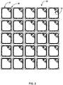
- FIG. 1 shows a perspective view of a prototype of an inductively coupled planar 5X5 square mesh high-pass two-dimensional ladder network resonator.
- FIG. 3 is a perspective view of a prototype of an inductively coupled high-pass two-dimensional ladder network resonator 30 for use in head imaging.
- the prototype of FIG. 3 shows a single conducting strip with the ends located at or near the middle of a leg of the resonator with a tuning capacitor 28 between the ends with the conducting strip mounted on a helmet 32. Additionally, the prototype of FIG.
- a head resonator used in a MR lab of a medical establishment uses capacitors 26 in place of trim capacitors 28 and the resonator elements 22 are covered with a dielectric material of sufficient strength to protect the resonator elements 22 from continual handling.
- the helmet 32 of the head resonator 30 has different sizes. For example, it is sized for neonatal, pediatric, and adult sized heads.
- the Kirchoff equations for the voltage on the meshes of FIG. 2 lead to a recursion relation.
- the constants ⁇ and ⁇ represent the coefficients of mutual inductance between nearest neighbors having parallel legs and those on the diagonal respectively. In one embodiment, 0 ⁇ ⁇ + ⁇ ⁇ 1/4
- the I m,n are the current amplitudes in the m,n th element.
- ⁇ and ⁇ are the integral mode numbers and ultimately determine the homogeneity of the magnetic field produced by each of the eigenfunctions.
- ⁇ and ⁇ are non-negligible and the individual circuit elements combine to produce normal modes of oscillation. Additionally, the circuit as a whole exhibits a high-pass behavior in that the lowest mode numbers corresponding to the most homogeneous eigenfunctions appear at the highest frequencies.
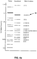
- FIG. 4a the theoretical and experimental eigenvalues for a 5 X 5 inductively coupled planar array is shown.
- the general case of a resonator with N x N elements will yield N 2 resonances with N(N-1) / 2 doublets and N singlets.
- the (1,5)(5,1) and (2,4)(4,2) doublets are further degenerated with the (3,3) singlet due to the neglected diagonal coupling.
- the (1,2)(2,1) doublet 40 yields a mode suitable for quadrature operation and has a B 1 profile suitable for imaging. It is important to note that other eigenmodes may be used for imaging as well with varying degrees of homogeneity for the spatial sensitivity. Some of these modes can be used in quadrature similar to the (1,2) or (2,1) pair.
- FIG. 4a-c Several normal modes for two representative arrays are shown in FIG. 4a-c .
- FIG. 4b the complete set of 25 modes for a 5 x 5 lattice structure is shown. Dark values correspond to negative currents and bright values correspond to positive currents.
- FIG. 4c the lowest 25 modes of a 30 x 30 array are shown to better illustrate the eigenfunctions.
- the eigenfunctions provide the relative amplitude of currents across the structure for each resonator element. For each mode, the amplitudes are used to create a B 1 profile. In the continuum limit, the current distribution field becomes a superposition of harmonic waves.
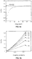
- line 50 corresponds to a 3x3 array
- line 52 corresponds to a 4x4 array
- line 54 corresponds to a 5x5 array
- line 56 corresponds to a 6x6 array
- line 58 corresponds to a 7x7 array
- line 60 corresponds to an 8x8 array.
- FIG. 7 An image acquired using the planar array prototype is shown in FIG. 7
- the total scan time for 21 slices was 30 seconds.
- all modes can be identified by using a small pickup coil connected to a network analyzer and an oscilloscope by measuring the relative field amplitudes across the structure.
- FIG. 9 shows a prototype of a body coil 70 used to demonstrate proof of concept.
- the body coil consists of a plurality of resonator elements 22 formed into a cylindrical shape.
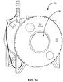
- the internal diameter 72 of the body coil is larger than the patient opening 80 of an MRI machine 82 (see FIG. 10 ) such that the body coil 70 can be mounted within the MRI machine 82.
- the body coil 70 is built into most MRI equipment and functions both as a transmit and receiver coil for a basic scan. This coil has a large measurement field, but does not have the high SNR of special coils. When specific receiver only coils are used (i.e., surface coils), the body coil 70 can serve as the transmit coil.
- each element 102 comprises a single loop of conducting strips 24 with one or more capacitors 26 separating portions of the conducting strips 24 at various points around the loop.
- trim capacitors 28 are used for the purpose of trimming the resonant frequency of the animal coil 100 to a desired frequency.
- the animal coil sizes range from 1 cm diameter/3 cm length, 2 cm diameter/5 cm length, 4 cm diameter/8 cm length, 6 cm diameter/12 cm length, and 8 cm diameter/16 cm length and the like in size.
- FIG. 13 shows a prototype of a finger coil 110, which is smaller than the animal coil 100. Similar to the animal coil, the finger coil 110 has a plurality of inductively coupled elements 102. In one embodiment, each element 102 comprises a single loop of conducting strips 24 with one or more capacitors 26 separating portions of the conducting strips 24 at various points around the loop. Just like the animal coil prototype, the finger coil prototype uses a trim capacitor 28 in each element 102 for the purpose of trimming the resonant frequency of the finger coil 100 to a desired frequency.
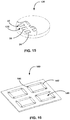
- FIG. 15 shows an illustration of an endo-coil 130.
- the endo-coil 130 is pill-sized (e.g., the size of a vitamin pill) and has a plurality of inductively coupled resonator elements 22 configured as a planar array 132.
- the conducting strips 24 and capacitors 26 of the resonator elements 22 are surface mounted to a flexible substrate.
- the flexible substrate and plurality of inductively coupled resonators are enclosed in a suitable biocompatible material as is known in the art.
- the endo-coil 130 may be either swallowed (e.g., taken as a pill) or inserted into the area of interest (e.g., in a spectroscopy procedure).
- the electron microscope has a limit of resolution of about 2nm. This resolution limitation is due to limitations of the lens used to focus electrons onto the sample. With an EM, remnants of dead cells, after fixation and heavy metal ion staining can be seen. Electrons are scattered as they pass through a thin section of the specimen, and then detected and projected onto an image on a fluorescent screen. Clinical MRI scans typically image a cube (voxel) of tissue 1x1x1 mm in size. While this is more or less satisfactory with respect to general human anatomy, a 1 mm cube is not sufficient.
- MR microscopy can take images with voxels that are 50 ⁇ m on a side in live animals, and with voxels of 10 ⁇ m on a side in dead, fixed specimens used in cellular imaging. To see details inside a human cell, voxels of 1 ⁇ m or less on a side are needed. It is recognized that at this level of resolution the diffusion limit for molecules of interest will be approached.
- micro coil designs have essential been smaller version of series wound solenoidal resonators.
- the two-dimensional ladder networks described herein represent a fundamentally new way to image microstructures, and can be manufactured at a micron scale.
- FIG. 16 shows an illustration of a micro-coil 140 for magnetic resonance imaging at cell level or spectroscopy of individual cells.
- the conducting strips 142 and capacitors 144 that form each resonator element 146 are of micron size scale.
- a plurality of resonator elements 146 are inductively coupled and are mounted on a clear biocompatible material and covered with a clear biocompatible material.
- the micro-coil 140 ranges in size from a cm in size down to sub-mm size and as technology progresses, probably less than 100 um in size.
- the structure of the inductively coupled high-pass two-dimensional ladder network resonator array can be used to reconstruct all the basis functions that are used to create an image.
- the collection of resonant modes (i.e., the eigenfunctions) of the array structure form a complete set of functions that allow any well-behaved function to be approximated across the structure. These functions can be described as Fourier components of an actual image.
- the steps to recreate an image with an array is to excite the array at each basis function (step 200). This is done by exciting the array at each resonant mode with the amplitude set to the magnitude of the Fourier coefficient necessary for subsequent reconstruction of the image. For example, referring to FIG.
- the number of modes depends on the number of elements in an array.
- the location of the modes depends on the capacitance values in the resonator elements for a given resonator size. In other words, the level of the eigenvalues with respect to frequency can be shifted upwardly or downwardly.
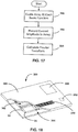
- FIGS. 18 and 19 the inductively coupled high-pass two-dimensional ladder network array can be used in credential card applications where the number of resonant modes (i.e. the size of an array), the mode frequency, and the amplitude of a resonant mode can be used to provide a relatively unique signature.
- credential card includes identification cards and smart cards.
- FIG. 18 provides an illustration of a credential card 300.
- the credential card 300 has an array 302 of resonators 304 that are internal to the credential card 300.
- the array 302 is embedded in a shell 306.
- the shell 306 may also enclose indicia such as a photo id 308 and/or other indicia 310 such as a barcode, a signature, a holographic layer, etc.
- the shell may be any material that insulates the array 302 and protects the array 302 from being tampered with by individuals.
- the credential card 300 also has an integrated circuit 310 (e.g., a "smart" chip) internal to the credential card 300.
- the array 302 may also serve as an antenna to provide power to the integrated circuit 310.
Landscapes
- Physics & Mathematics (AREA)
- General Physics & Mathematics (AREA)
- Condensed Matter Physics & Semiconductors (AREA)
- Engineering & Computer Science (AREA)
- Theoretical Computer Science (AREA)
- Magnetic Resonance Imaging Apparatus (AREA)
- Credit Cards Or The Like (AREA)
Claims (34)
- Zweidimensionaler Hochpass-Radiofrequenz-Gitternetzwerk-Resonator (20), der eine Sammlung ist von:Einer Mehrzahl von Resonatoren (22), die eine induktiv gekoppelte zweidimensionale Resonatoranordnung bilden, die sich in zwei Richtungen erstreckt und deren Aufbau in zwei oder drei Dimensionen ausgestaltet werden kann, so dass der Aufbau bei einer Vielzahl von Anwendungen verwendet werden kann einschließlich einer deckenartigen Spule, einer Mikrospule, einer Körperspule, einer Endospule, zylindrischen Spulen einschließlich Tierspulen und Kopfspulen, und von spezialisierten Spulen wie Handspulen, Knöchelspulen, wie auch Berechtigungskarten-Anwendungen,wobei die Mehrzahl von Resonatoren (22) nur in den zwei genannten Richtungen induktiv gekoppelt ist, wobei jeder induktiv gekoppelte Resonator wenigstens einen Leiterstreifen (24), der eine Selbstinduktivität (L) aufweist, in einer solchen Form, dass jedes Ende eines Leiterstreifens (24) mit einem Kondensator (26) verbunden ist, der mit einem anderen Ende des wenigstens einen Leiterstreifens (24) verbunden ist, beinhaltet, wobei die Resonatoranordnung als Ganzes ein Hochpassverhalten zeigt, derart, dass die niedrigsten Modenzahlen, die den homogensten Resonanzmoden entsprechen, bei den höchsten Frequenzen auftreten.
- Zweidimensionaler Hochpass-Gitternetzwerk-Resonator nach Anspruch 1, bei dem die Mehrzahl induktiv gekoppelter Resonatoren (22) eine zylindrisch geformte Anordnung (70) nicht überlappender induktiv gekoppelter Resonatoren (22) bildet.
- Zweidimensionaler Hochpass-Gitternetzwerk-Resonator nach Anspruch 2, bei dem die zylindrisch geformte Anordnung (70) für MRT-Anwendungen einen Innendurchmesser aufweist, der größer ist als ein Außendurchmesser eines menschlichen Körpers.
- Zweidimensionaler Hochpass-Gitternetzwerk-Resonator nach Anspruch 3, bei dem die zylindrisch geformte Anordnung (70) eine Spule eines MRT-Tomographen ist.
- Zweidimensionaler Hochpass-Gitternetzwerk-Resonator nach Anspruch 3, bei dem der wenigstens eine Leiterstreifen (24) eine Mehrzahl von Leiterstreifen beinhaltet, wobei die Mehrzahl von Leiterstreifen (24) miteinander verbunden ist, so dass jedes Ende der Mehrzahl von Leiterstreifen mit einem Kondensator (26) verbunden ist.
- Zweidimensionaler Hochpass-Gitternetzwerk-Resonator nach Anspruch 5, bei dem jedes Ende der Mehrzahl von Leiterstreifen (24) mit dem Kondensator (26) verbunden ist, so dass jeder der Mehrzahl von nicht überlappenden induktiv gekoppelten Resonatoren (22) eine Rechteckform bildet mit einem Kondensator (26) an jeder Ecke der Rechteckform.
- Zweidimensionaler Hochpass-Gitternetzwerk-Resonator nach Anspruch 2, bei dem die zylindrisch geformte Anordnung (70) für MRT-Anwendungen einen Innendurchmesser aufweist, der größer ist als ein Außendurchmesser eines Tierkörpers.
- Zweidimensionaler Hochpass-Gitternetzwerk-Resonator nach Anspruch 2, bei dem die zylindrisch geformte Anordnung (70) für MRT-Anwendungen einen Innendurchmesser aufweist, der größer ist als ein Aussendurchmesser eines menschlichen Fingers.
- Zweidimensionaler Hochpass-Gitternetzwerk-Resonator nach Anspruch 1, bei dem die Mehrheit induktiv gekoppelter Resonatoren (22) für MRT-Anwendungen eine im Wesentlichen elliptisch geformte Anordnung (120) induktiv gekoppelter Resonatoren (22), die über eine Hand passt, bildet.
- Zweidimensionaler Hochpass-Gitternetzwerk-Resonator nach Anspruch 9, bei dem die im Wesentlichen elliptisch geformte Anordnung (120) nicht überlappender, induktiv gekoppelter Resonatoren (22) mit einem elektrisch isolierenden Material abgedeckt sind.
- Zweidimensionaler Hochpass-Gitternetzwerk-Resonator nach Anspruch 1, bei dem die Mehrheit induktiv gekoppelter Resonatoren (22) für MRT-Anwendungen eine Anordnung nicht überlappender induktiv gekoppelter Resonatoren (22), die so geformt ist, dass sie über ein Glied des menschlichen Körpers passt, bildet.
- Zweidimensionaler Hochpass-Gitternetzwerk-Resonator nach Anspruch 1, bei dem die Mehrheit induktiv gekoppelter Resonatoren (22) für MRT-Anwendungen so geformt ist, das sie über einen Kopf passt.
- Zweidimensionaler Hochpass-Gitternetzwerk-Resonator nach Anspruch 12, bei dem der wenigstens eine Leiterstreifen (24) eine Mehrzahl von Leiterstreifen (24) beinhaltet, wobei die Mehrzahl von Leiterstreifen (24) miteinander verbunden ist, so dass jedes Ende der Mehrzahl von Leiterstreifen (24) mit einem Kondensator (26) verbunden ist.
- Zweidimensionaler Hochpass-Gitternetzwerk-Resonator nach Anspruch 1, bei dem die Mehrzahl induktiv gekoppelter Resonatoren (22) an einem flexiblen Substrat angebracht ist.
- Zweidimensionaler Hochpass-Gitternetzwerk-Resonator nach Anspruch 14, bei dem das flexible Substrat im Wesentlichen formbar ist.
- Zweidimensionaler Hochpass-Gitternetzwerk-Resonator nach Anspruch 14, bei dem die Mehrzahl von induktiv gekoppelten Resonatoren (22) mit einem elektrisch isolierenden Material abgedeckt ist.
- Zweidimensionaler Hochpass-Gitternetzwerk-Resonator nach Anspruch 1, bei dem die Mehrzahl von induktiv gekoppelten Resonatoren (22) so bemessen ist, dass der zweidimensionale Hochpass-Gitternetzwerk-Resonator eine Größe zwischen ungefähr 1 Zentimeter und ungefähr 100 Mikrometern aufweist.
- Zweidimensionaler Hochpass-Gitternetzwerk-Resonator nach Anspruch 17, bei dem das zweidimensionale Hochpass-Gitternetzwerk (20) mit einem biokompatiblen Material bedeckt ist.
- Zweidimensionaler Hochpass-Gitternetzwerk-Resonator nach Anspruch 1, bei dem die Mehrzahl induktiv gekoppelter Resonatoren (22) für MRT-Anwendungen eine Endospule (130) bildet.
- Zweidimensionaler Hochpass-Gitternetzwerk-Resonator nach Anspruch 19, bei dem die Endospule (130) Pillengröße hat.
- Zweidimensionaler Hochpass-Gitternetzwerk-Resonator nach Anspruch 1, bei dem die Mehrzahl induktiv gekoppelter Resonatoren (22) eine Anordnung (302) bildet, die in eine Berechtigungskarte (300) eingebettet ist.
- Zweidimensionaler Hochpass-Gitternetzwerk-Resonator nach Anspruch 21, bei dem die Berechtigungskarte (300) weiterhin wenigstens ein Identifikationskennzeichen (308, 310) auf einer äußeren Oberfläche der Berechtigungskarte (300) beinhaltet.
- Zweidimensionaler Hochpass-Gitternetzwerk-Resonator nach Anspruch 22, bei dem das wenigstens eine Identifikationskennzeichen ein fotografisches Bild (308) beinhaltet.
- Zweidimensionaler Hochpass-Gitternetzwerk-Resonator nach Anspruch 21, bei dem die Berechtigungskarte (300) weiterhin einen integrierten Schaltkreis (310), der in die Berechtigungskarte (300) eingebettet ist, beinhaltet.
- Zweidimensionaler Hochpass-Gitternetzwerk-Resonator nach Anspruch 21, bei dem die Anordnung eine Anordnung (22) ist, die eine Mindestgröße einer fünf mal fünf-Anordnung aufweist.
- Verfahren zum Rekonstruieren der Basisfunktionen eines zweidimensionalen Hochpass-Gitternetzwerk (20) -Resonators nach Anspruch 1, wobei das Verfahren folgende Schritte beinhaltet:Erregen des zweidimensionalen Hochpass-Gitternetzwerk (20) -Resonators in jeder Resonanzmode;Detektieren einer Stromamplitude in dem zweidimensionalen Hochpass-Gitternetzwerk (20) -Resonator in jeder Resonanzmode; und Berechnen einer Fouriertransformation unter Verwendung der Stromamplitude, die in jeder Resonanzmode detektiert wurde, als Fourierkoeffizienten in der Fouriertransformation.
- Verfahren nach Anspruch 26, bei dem der Schritt des Detektierens der Stromamplitude den Schritt des Detektierens der Stromamplitude mit einer Aufnahmespule beinhaltet.
- Verfahren nach Anspruch 26, bei dem der Schritt des Erregens des zweidimensionalen Hochpass-Gitternetzwerk-Resonators in jeder Resonanzmode den Schritt des Erregens des zweidimensionalen Hochpass-Gitternetzwerk-Resonators in jeder Resonanzmode mit einer Amplitude, die auf eine Größe des Fourierkoeffizienten, der der Eigenfunktion der Resonanzmode entspricht, eingestellt wird, beinhaltet.
- Verfahren nach Anspruch 26, bei dem der Schritt des Erregens des zweidimensionalen Hochpass-Gitternetzwerk (20) -Resonators in jeder Resonanzmode den Schritt des gleichzeitigen Erregens des zweidimensionalen Hochpass-Gitternetzwerk-Resonators in jeder Resonanzmode beinhaltet.
- Verfahren zum Validieren einer Berechtigungskarte nach Anspruch 21, wobei das Verfahren folgende Schritte beinhaltet: Bestimmen der Resonanzmoden der Anordnung (302); Vergleichen der Resonanzmoden mit abgespeicherten Resonanzmoden von Ausweiskarten (300); Validieren der Ausweiskarte, wenn eine Übereinstimmung festgestellt wird.
- Verfahren nach Anspruch 30, bei dem der Schritt des Bestimmens der Resonanzmoden der Anordnung (302) den Schritt beinhaltet, die Berechtigungskarte (300) einem Frequenzdurchlauf auszusetzen.
- Verfahren nach Anspruch 30, weiterhin beinhaltend den Schritt des Erzeugens einer Warnung, wenn keine Übereinstimmung festgestellt wird.
- Verfahren nach Anspruch 30, weiterhin beinhaltend den Schritt des Erzeugens eines Alarms, wenn keine Übereinstimmung festgestellt wird.
- Verfahren nach Anspruch 30, weiterhin beinhaltend den Schritt des Bestimmens, warum keine Übereinstimmung festgestellt wurde, wenn keine Übereinstimmung festgestellt wurde.
Applications Claiming Priority (3)
| Application Number | Priority Date | Filing Date | Title |
|---|---|---|---|
| US67159705P | 2005-04-15 | 2005-04-15 | |
| US11/403,355 US7642781B2 (en) | 2005-04-15 | 2006-04-13 | High-pass two-dimensional ladder network resonator |
| PCT/US2006/014269 WO2006113545A2 (en) | 2005-04-15 | 2006-04-14 | High-pass two-dimensional ladder network resonator |
Publications (3)
| Publication Number | Publication Date |
|---|---|
| EP1877835A2 EP1877835A2 (de) | 2008-01-16 |
| EP1877835A4 EP1877835A4 (de) | 2012-04-11 |
| EP1877835B1 true EP1877835B1 (de) | 2019-09-18 |
Family
ID=37115787
Family Applications (1)
| Application Number | Title | Priority Date | Filing Date |
|---|---|---|---|
| EP06750335.9A Expired - Lifetime EP1877835B1 (de) | 2005-04-15 | 2006-04-14 | Zweidimensionaler hochpass-leiternetzwerk-resonator |
Country Status (5)
| Country | Link |
|---|---|
| US (1) | US7642781B2 (de) |
| EP (1) | EP1877835B1 (de) |
| JP (1) | JP2008538311A (de) |
| CN (1) | CN101467069B (de) |
| WO (1) | WO2006113545A2 (de) |
Families Citing this family (30)
| Publication number | Priority date | Publication date | Assignee | Title |
|---|---|---|---|---|
| US9808262B2 (en) | 2006-02-15 | 2017-11-07 | Howmedica Osteonics Corporation | Arthroplasty devices and related methods |
| CA2642615A1 (en) | 2006-02-15 | 2007-08-30 | Otismed Corp | Arthroplasty jigs and related methods |
| US8460302B2 (en) | 2006-12-18 | 2013-06-11 | Otismed Corporation | Arthroplasty devices and related methods |
| EP2115485A1 (de) * | 2007-02-26 | 2009-11-11 | Koninklijke Philips Electronics N.V. | Doppelt resonante hochfeld-funkfrequenzoberflächenspulen für magnetresonanz |
| ATE505736T1 (de) | 2007-09-28 | 2011-04-15 | Max Planck Gesellschaft | Streifenleiter-antenne und antennenanordnung für ein magnetresonanzgerät |
| US8460303B2 (en) | 2007-10-25 | 2013-06-11 | Otismed Corporation | Arthroplasty systems and devices, and related methods |
| US10582934B2 (en) | 2007-11-27 | 2020-03-10 | Howmedica Osteonics Corporation | Generating MRI images usable for the creation of 3D bone models employed to make customized arthroplasty jigs |
| US8160345B2 (en) | 2008-04-30 | 2012-04-17 | Otismed Corporation | System and method for image segmentation in generating computer models of a joint to undergo arthroplasty |
| US8777875B2 (en) | 2008-07-23 | 2014-07-15 | Otismed Corporation | System and method for manufacturing arthroplasty jigs having improved mating accuracy |
| US8545509B2 (en) | 2007-12-18 | 2013-10-01 | Otismed Corporation | Arthroplasty system and related methods |
| US8480679B2 (en) | 2008-04-29 | 2013-07-09 | Otismed Corporation | Generation of a computerized bone model representative of a pre-degenerated state and useable in the design and manufacture of arthroplasty devices |
| US8221430B2 (en) | 2007-12-18 | 2012-07-17 | Otismed Corporation | System and method for manufacturing arthroplasty jigs |
| US8737700B2 (en) * | 2007-12-18 | 2014-05-27 | Otismed Corporation | Preoperatively planning an arthroplasty procedure and generating a corresponding patient specific arthroplasty resection guide |
| US8617171B2 (en) | 2007-12-18 | 2013-12-31 | Otismed Corporation | Preoperatively planning an arthroplasty procedure and generating a corresponding patient specific arthroplasty resection guide |
| US8734455B2 (en) | 2008-02-29 | 2014-05-27 | Otismed Corporation | Hip resurfacing surgical guide tool |
| US8617175B2 (en) | 2008-12-16 | 2013-12-31 | Otismed Corporation | Unicompartmental customized arthroplasty cutting jigs and methods of making the same |
| TWI383168B (zh) * | 2009-04-06 | 2013-01-21 | Univ Nat Taiwan | Conversion device for nuclear magnetic resonance analysis and method thereof |
| DE102012201370B4 (de) * | 2012-01-31 | 2016-02-11 | Siemens Aktiengesellschaft | Halterung für Double-Loop-Coil (Doppel-Schleifen-Spule) für z.B. MCP-Aufnahmen |
| DE102012213594B4 (de) * | 2012-08-01 | 2016-07-28 | Siemens Healthcare Gmbh | MR- Oberflächenspule mit integrierter automatischer Patientenfixierung |
| US9402637B2 (en) | 2012-10-11 | 2016-08-02 | Howmedica Osteonics Corporation | Customized arthroplasty cutting guides and surgical methods using the same |
| GB2551302B (en) * | 2013-01-08 | 2018-02-28 | Pulseteq Ltd | Radiofrequency coils |
| US11730970B2 (en) | 2013-03-14 | 2023-08-22 | The Methodist Hospital | Method and apparatus for providing transcranial magnetic stimulation (TMS) to an individual |
| WO2015023980A2 (en) * | 2013-08-15 | 2015-02-19 | The Methodist Hospital | Method and apparatus for ppoviding transcranial magnetic stimulation (tms) to an individual |
| US9720059B2 (en) * | 2013-04-03 | 2017-08-01 | National Taiwan University | Multi-channel coil array for parallel magnetic resonance imaging |
| CN105393131B (zh) * | 2013-07-18 | 2019-11-19 | 皇家飞利浦有限公司 | 用于mri的基于叠层设计的射频线圈单元 |
| GB2517987A (en) * | 2013-09-09 | 2015-03-11 | Isis Innovation | Waveguide |
| JP6791760B2 (ja) | 2014-03-14 | 2020-11-25 | ザ ジェネラル ホスピタル コーポレイション | 低磁場マルチチャネル撮像のためのシステムおよび方法 |
| CN106133544B (zh) * | 2014-03-24 | 2020-01-07 | 皇家飞利浦有限公司 | 磁共振成像rf天线 |
| GB201420936D0 (en) * | 2014-11-25 | 2015-01-07 | Isis Innovation | Radio frequency cavities |
| US11686792B2 (en) * | 2017-04-30 | 2023-06-27 | New York University | Receive coil arrangement and method for use thereof |
Citations (2)
| Publication number | Priority date | Publication date | Assignee | Title |
|---|---|---|---|---|
| US5003265A (en) * | 1988-05-18 | 1991-03-26 | U.S. Philips Corporation | Magnetic resonance imaging apparatus comprising an RF coil system |
| US6307373B1 (en) * | 1998-05-28 | 2001-10-23 | Picker International, Inc. | Anti-aliasing transmitter coil array for magnetic resonance |
Family Cites Families (27)
| Publication number | Priority date | Publication date | Assignee | Title |
|---|---|---|---|---|
| US3938091A (en) * | 1972-03-17 | 1976-02-10 | Atalla Technovations Company | Personal verification system |
| US4680548A (en) * | 1984-10-09 | 1987-07-14 | General Electric Company | Radio frequency field coil for NMR |
| JPS641309A (en) * | 1987-06-24 | 1989-01-05 | Matsushita Electric Ind Co Ltd | Resonator |
| DE4038106C2 (de) * | 1989-12-12 | 2002-04-18 | Siemens Ag | Oberflächenresonator für einen Kernspintomographen |
| US5194811A (en) * | 1990-08-02 | 1993-03-16 | Fox Chase Cancer Center | Radio frequency volume resonator for nuclear magnetic resonance |
| US5212450A (en) | 1990-10-25 | 1993-05-18 | Fox Chase Cancer Center | Radio frequency volume resonator for nuclear magnetic resonance |
| US5191315A (en) | 1990-12-31 | 1993-03-02 | Pitney Bowes Inc. | Deactivatable electronic article surveillance markers using short semi-hard magnetic wires |
| US5515855A (en) | 1994-08-05 | 1996-05-14 | Sloan-Kettering Institute For Cancer Research | Dome-shaped resonator for nuclear magnetic resonance imaging and spectroscopy |
| US5682893A (en) | 1994-08-05 | 1997-11-04 | Sloan-Kettering Institute For Cancer Research | Dome-shaped resonator for nuclear magnetic resonance imaging and spectroscopy |
| US5729201A (en) | 1995-06-29 | 1998-03-17 | International Business Machines Corporation | Identification tags using amorphous wire |
| JP3127792B2 (ja) * | 1995-07-19 | 2001-01-29 | 株式会社村田製作所 | Lc共振器およびlcフィルタ |
| US5998999A (en) | 1996-12-12 | 1999-12-07 | Picker International, Inc. | Volume RF coils with integrated high resolution focus coils for magnetic resonance imaging |
| IL119943A (en) | 1996-12-31 | 2000-11-21 | On Track Innovations Ltd | Contact/contactless data transaction card |
| US6023166A (en) * | 1997-11-19 | 2000-02-08 | Fonar Corporation | MRI antenna |
| US6008649A (en) * | 1997-12-23 | 1999-12-28 | General Electric Company | RF coil apparatus for MR system with lateral B0 field |
| US6175727B1 (en) * | 1998-01-09 | 2001-01-16 | Texas Instruments Israel Ltd. | Suspended printed inductor and LC-type filter constructed therefrom |
| US6344745B1 (en) | 1998-11-25 | 2002-02-05 | Medrad, Inc. | Tapered birdcage resonator for improved homogeneity in MRI |
| DE10056807A1 (de) | 2000-11-16 | 2002-05-23 | Philips Corp Intellectual Pty | HF-Flächenresonator für Magnetresonanz-Bildgerät |
| JP2002261561A (ja) * | 2001-02-27 | 2002-09-13 | Matsushita Electric Ind Co Ltd | フィルタ部品 |
| CA2492004C (en) | 2002-07-09 | 2009-02-03 | Bnc Ip Switzerland Gmbh | System and method for providing secure identification solutions |
| AU2003302444A1 (en) | 2002-11-27 | 2004-06-18 | Koninklijke Philips Electronics N.V. | Degenerate birdcage coil and transmit/receive apparatus and method for same |
| KR100517488B1 (ko) * | 2002-11-30 | 2005-10-04 | 한국전자통신연구원 | 개구면을 이용한 개방 루프 공진 필터 |
| US6776332B2 (en) * | 2002-12-26 | 2004-08-17 | Micropin Technologies Inc. | System and method for validating and operating an access card |
| US7389939B2 (en) | 2003-09-26 | 2008-06-24 | Digimarc Corporation | Optically variable security features having covert forensic features |
| US20050156318A1 (en) | 2004-01-15 | 2005-07-21 | Douglas Joel S. | Security marking and security mark |
| US7508283B2 (en) * | 2004-03-26 | 2009-03-24 | The Regents Of The University Of California | Composite right/left handed (CRLH) couplers |
| US7292038B2 (en) * | 2005-05-02 | 2007-11-06 | Doty Scientific, Inc. | Double-balanced double-tuned CP birdcage with similar field profiles |
-
2006
- 2006-04-13 US US11/403,355 patent/US7642781B2/en not_active Expired - Fee Related
- 2006-04-14 CN CN200680012132XA patent/CN101467069B/zh not_active Expired - Fee Related
- 2006-04-14 JP JP2008506788A patent/JP2008538311A/ja active Pending
- 2006-04-14 EP EP06750335.9A patent/EP1877835B1/de not_active Expired - Lifetime
- 2006-04-14 WO PCT/US2006/014269 patent/WO2006113545A2/en not_active Ceased
Patent Citations (2)
| Publication number | Priority date | Publication date | Assignee | Title |
|---|---|---|---|---|
| US5003265A (en) * | 1988-05-18 | 1991-03-26 | U.S. Philips Corporation | Magnetic resonance imaging apparatus comprising an RF coil system |
| US6307373B1 (en) * | 1998-05-28 | 2001-10-23 | Picker International, Inc. | Anti-aliasing transmitter coil array for magnetic resonance |
Also Published As
| Publication number | Publication date |
|---|---|
| JP2008538311A (ja) | 2008-10-23 |
| US7642781B2 (en) | 2010-01-05 |
| EP1877835A4 (de) | 2012-04-11 |
| WO2006113545A2 (en) | 2006-10-26 |
| US20060244448A1 (en) | 2006-11-02 |
| CN101467069A (zh) | 2009-06-24 |
| CN101467069B (zh) | 2012-06-20 |
| WO2006113545A3 (en) | 2009-01-22 |
| EP1877835A2 (de) | 2008-01-16 |
Similar Documents
| Publication | Publication Date | Title |
|---|---|---|
| US7642781B2 (en) | High-pass two-dimensional ladder network resonator | |
| EP2458396A1 (de) | Magnetische Bildgebung mit einer Metamateriallinse | |
| US8798719B2 (en) | Method of utilization of high dielectric constant (HDC) materials for reducing SAR and enhancing SNR in MRI | |
| Puchnin et al. | Metamaterial inspired wireless coil for clinical breast imaging | |
| US11686792B2 (en) | Receive coil arrangement and method for use thereof | |
| JP2010512924A (ja) | Mrイメージングシステムに用いられるrfコイル | |
| Yan et al. | Simulation verification of SNR and parallel imaging improvements by ICE-decoupled loop array in MRI | |
| Brui et al. | Adjustable subwavelength metasurface‐inspired resonator for magnetic resonance imaging | |
| US11002810B2 (en) | RF resonator with a Lenz lens | |
| US6535084B1 (en) | Method and apparatus for designing an RF coil assembly | |
| US9429634B2 (en) | MRI coil design with volumetric trough-shaped coil elements | |
| CN108663641B (zh) | 用于磁共振设备的射频线圈 | |
| Zhu et al. | Detunable wireless Litzcage coil for human head MRI at 1.5 T | |
| CN107835658A (zh) | 磁共振成像机 | |
| US20140049259A1 (en) | Resonant magnetic ring antenna | |
| US7420371B2 (en) | Slab-selective RF coil for MR system | |
| US9823319B2 (en) | Radio frequency resonator and magnetic resonance imaging apparatus comprising the same | |
| Lippke et al. | Investigation of a digitally-reconfigurable metasurface for magnetic resonance imaging | |
| US11719775B1 (en) | RF receiver coil with equal perimeter loops | |
| JP6901483B2 (ja) | 磁気共鳴検査システム用の無線周波数コイルアレイ | |
| KR102564686B1 (ko) | 특정 핵종의 몰농도를 측정하기 위한 자기공명영상용 rf 코일 | |
| US20140062482A1 (en) | Acquisition of mr data with sequential selection of resonant modes of the rf coil asssembly | |
| US20220137165A1 (en) | Coil arrangement, mr system, in particular mri and/or mrs system, with such a coil arrangement and use of such a coil arrangement | |
| US7106062B1 (en) | Method and system for reducing coupling in magnetic resonance RF coil arrays | |
| Giovannetti et al. | Capacitors quality effect in magnetic resonance radiofrequency coils |
Legal Events
| Date | Code | Title | Description |
|---|---|---|---|
| PUAI | Public reference made under article 153(3) epc to a published international application that has entered the european phase |
Free format text: ORIGINAL CODE: 0009012 |
|
| 17P | Request for examination filed |
Effective date: 20071110 |
|
| AK | Designated contracting states |
Kind code of ref document: A2 Designated state(s): AT BE BG CH CY CZ DE DK EE ES FI FR GB GR HU IE IS IT LI LT LU LV MC NL PL PT RO SE SI SK TR |
|
| AX | Request for extension of the european patent |
Extension state: AL BA HR MK YU |
|
| DAX | Request for extension of the european patent (deleted) | ||
| R17D | Deferred search report published (corrected) |
Effective date: 20090122 |
|
| RIN1 | Information on inventor provided before grant (corrected) |
Inventor name: BALLON, DOUGLAS, J. Inventor name: VOSS, HENNING, U. |
|
| A4 | Supplementary search report drawn up and despatched |
Effective date: 20120314 |
|
| RIC1 | Information provided on ipc code assigned before grant |
Ipc: G06K 19/077 20060101ALI20120308BHEP Ipc: G06K 19/07 20060101ALI20120308BHEP Ipc: G01R 33/34 20060101ALI20120308BHEP Ipc: G01V 3/00 20060101AFI20120308BHEP |
|
| 17Q | First examination report despatched |
Effective date: 20130320 |
|
| STAA | Information on the status of an ep patent application or granted ep patent |
Free format text: STATUS: EXAMINATION IS IN PROGRESS |
|
| REG | Reference to a national code |
Ref country code: DE Ref legal event code: R079 Ref document number: 602006058598 Country of ref document: DE Free format text: PREVIOUS MAIN CLASS: G01V0003000000 Ipc: G01R0033341500 |
|
| GRAP | Despatch of communication of intention to grant a patent |
Free format text: ORIGINAL CODE: EPIDOSNIGR1 |
|
| STAA | Information on the status of an ep patent application or granted ep patent |
Free format text: STATUS: GRANT OF PATENT IS INTENDED |
|
| RIC1 | Information provided on ipc code assigned before grant |
Ipc: G01R 33/3415 20060101AFI20190313BHEP Ipc: G06K 19/067 20060101ALI20190313BHEP Ipc: G01R 33/34 20060101ALI20190313BHEP Ipc: G01R 33/36 20060101ALI20190313BHEP |
|
| INTG | Intention to grant announced |
Effective date: 20190403 |
|
| GRAS | Grant fee paid |
Free format text: ORIGINAL CODE: EPIDOSNIGR3 |
|
| GRAA | (expected) grant |
Free format text: ORIGINAL CODE: 0009210 |
|
| STAA | Information on the status of an ep patent application or granted ep patent |
Free format text: STATUS: THE PATENT HAS BEEN GRANTED |
|
| AK | Designated contracting states |
Kind code of ref document: B1 Designated state(s): AT BE BG CH CY CZ DE DK EE ES FI FR GB GR HU IE IS IT LI LT LU LV MC NL PL PT RO SE SI SK TR |
|
| REG | Reference to a national code |
Ref country code: GB Ref legal event code: FG4D |
|
| REG | Reference to a national code |
Ref country code: CH Ref legal event code: EP |
|
| REG | Reference to a national code |
Ref country code: DE Ref legal event code: R096 Ref document number: 602006058598 Country of ref document: DE |
|
| REG | Reference to a national code |
Ref country code: AT Ref legal event code: REF Ref document number: 1181982 Country of ref document: AT Kind code of ref document: T Effective date: 20191015 |
|
| REG | Reference to a national code |
Ref country code: IE Ref legal event code: FG4D |
|
| REG | Reference to a national code |
Ref country code: NL Ref legal event code: MP Effective date: 20190918 |
|
| PG25 | Lapsed in a contracting state [announced via postgrant information from national office to epo] |
Ref country code: BG Free format text: LAPSE BECAUSE OF FAILURE TO SUBMIT A TRANSLATION OF THE DESCRIPTION OR TO PAY THE FEE WITHIN THE PRESCRIBED TIME-LIMIT Effective date: 20191218 Ref country code: LT Free format text: LAPSE BECAUSE OF FAILURE TO SUBMIT A TRANSLATION OF THE DESCRIPTION OR TO PAY THE FEE WITHIN THE PRESCRIBED TIME-LIMIT Effective date: 20190918 Ref country code: FI Free format text: LAPSE BECAUSE OF FAILURE TO SUBMIT A TRANSLATION OF THE DESCRIPTION OR TO PAY THE FEE WITHIN THE PRESCRIBED TIME-LIMIT Effective date: 20190918 Ref country code: SE Free format text: LAPSE BECAUSE OF FAILURE TO SUBMIT A TRANSLATION OF THE DESCRIPTION OR TO PAY THE FEE WITHIN THE PRESCRIBED TIME-LIMIT Effective date: 20190918 |
|
| REG | Reference to a national code |
Ref country code: LT Ref legal event code: MG4D |
|
| PG25 | Lapsed in a contracting state [announced via postgrant information from national office to epo] |
Ref country code: GR Free format text: LAPSE BECAUSE OF FAILURE TO SUBMIT A TRANSLATION OF THE DESCRIPTION OR TO PAY THE FEE WITHIN THE PRESCRIBED TIME-LIMIT Effective date: 20191219 Ref country code: LV Free format text: LAPSE BECAUSE OF FAILURE TO SUBMIT A TRANSLATION OF THE DESCRIPTION OR TO PAY THE FEE WITHIN THE PRESCRIBED TIME-LIMIT Effective date: 20190918 |
|
| REG | Reference to a national code |
Ref country code: AT Ref legal event code: MK05 Ref document number: 1181982 Country of ref document: AT Kind code of ref document: T Effective date: 20190918 |
|
| PG25 | Lapsed in a contracting state [announced via postgrant information from national office to epo] |
Ref country code: AT Free format text: LAPSE BECAUSE OF FAILURE TO SUBMIT A TRANSLATION OF THE DESCRIPTION OR TO PAY THE FEE WITHIN THE PRESCRIBED TIME-LIMIT Effective date: 20190918 Ref country code: IT Free format text: LAPSE BECAUSE OF FAILURE TO SUBMIT A TRANSLATION OF THE DESCRIPTION OR TO PAY THE FEE WITHIN THE PRESCRIBED TIME-LIMIT Effective date: 20190918 Ref country code: PT Free format text: LAPSE BECAUSE OF FAILURE TO SUBMIT A TRANSLATION OF THE DESCRIPTION OR TO PAY THE FEE WITHIN THE PRESCRIBED TIME-LIMIT Effective date: 20200120 Ref country code: PL Free format text: LAPSE BECAUSE OF FAILURE TO SUBMIT A TRANSLATION OF THE DESCRIPTION OR TO PAY THE FEE WITHIN THE PRESCRIBED TIME-LIMIT Effective date: 20190918 Ref country code: EE Free format text: LAPSE BECAUSE OF FAILURE TO SUBMIT A TRANSLATION OF THE DESCRIPTION OR TO PAY THE FEE WITHIN THE PRESCRIBED TIME-LIMIT Effective date: 20190918 Ref country code: NL Free format text: LAPSE BECAUSE OF FAILURE TO SUBMIT A TRANSLATION OF THE DESCRIPTION OR TO PAY THE FEE WITHIN THE PRESCRIBED TIME-LIMIT Effective date: 20190918 Ref country code: RO Free format text: LAPSE BECAUSE OF FAILURE TO SUBMIT A TRANSLATION OF THE DESCRIPTION OR TO PAY THE FEE WITHIN THE PRESCRIBED TIME-LIMIT Effective date: 20190918 Ref country code: ES Free format text: LAPSE BECAUSE OF FAILURE TO SUBMIT A TRANSLATION OF THE DESCRIPTION OR TO PAY THE FEE WITHIN THE PRESCRIBED TIME-LIMIT Effective date: 20190918 |
|
| PG25 | Lapsed in a contracting state [announced via postgrant information from national office to epo] |
Ref country code: IS Free format text: LAPSE BECAUSE OF FAILURE TO SUBMIT A TRANSLATION OF THE DESCRIPTION OR TO PAY THE FEE WITHIN THE PRESCRIBED TIME-LIMIT Effective date: 20200224 Ref country code: SK Free format text: LAPSE BECAUSE OF FAILURE TO SUBMIT A TRANSLATION OF THE DESCRIPTION OR TO PAY THE FEE WITHIN THE PRESCRIBED TIME-LIMIT Effective date: 20190918 Ref country code: CZ Free format text: LAPSE BECAUSE OF FAILURE TO SUBMIT A TRANSLATION OF THE DESCRIPTION OR TO PAY THE FEE WITHIN THE PRESCRIBED TIME-LIMIT Effective date: 20190918 |
|
| REG | Reference to a national code |
Ref country code: DE Ref legal event code: R097 Ref document number: 602006058598 Country of ref document: DE |
|
| PLBE | No opposition filed within time limit |
Free format text: ORIGINAL CODE: 0009261 |
|
| STAA | Information on the status of an ep patent application or granted ep patent |
Free format text: STATUS: NO OPPOSITION FILED WITHIN TIME LIMIT |
|
| PG2D | Information on lapse in contracting state deleted |
Ref country code: IS |
|
| PG25 | Lapsed in a contracting state [announced via postgrant information from national office to epo] |
Ref country code: DK Free format text: LAPSE BECAUSE OF FAILURE TO SUBMIT A TRANSLATION OF THE DESCRIPTION OR TO PAY THE FEE WITHIN THE PRESCRIBED TIME-LIMIT Effective date: 20190918 Ref country code: IS Free format text: LAPSE BECAUSE OF FAILURE TO SUBMIT A TRANSLATION OF THE DESCRIPTION OR TO PAY THE FEE WITHIN THE PRESCRIBED TIME-LIMIT Effective date: 20200119 |
|
| 26N | No opposition filed |
Effective date: 20200619 |
|
| PG25 | Lapsed in a contracting state [announced via postgrant information from national office to epo] |
Ref country code: SI Free format text: LAPSE BECAUSE OF FAILURE TO SUBMIT A TRANSLATION OF THE DESCRIPTION OR TO PAY THE FEE WITHIN THE PRESCRIBED TIME-LIMIT Effective date: 20190918 |
|
| PG25 | Lapsed in a contracting state [announced via postgrant information from national office to epo] |
Ref country code: MC Free format text: LAPSE BECAUSE OF FAILURE TO SUBMIT A TRANSLATION OF THE DESCRIPTION OR TO PAY THE FEE WITHIN THE PRESCRIBED TIME-LIMIT Effective date: 20190918 |
|
| REG | Reference to a national code |
Ref country code: CH Ref legal event code: PL |
|
| PG25 | Lapsed in a contracting state [announced via postgrant information from national office to epo] |
Ref country code: CH Free format text: LAPSE BECAUSE OF NON-PAYMENT OF DUE FEES Effective date: 20200430 Ref country code: LI Free format text: LAPSE BECAUSE OF NON-PAYMENT OF DUE FEES Effective date: 20200430 Ref country code: LU Free format text: LAPSE BECAUSE OF NON-PAYMENT OF DUE FEES Effective date: 20200414 |
|
| REG | Reference to a national code |
Ref country code: BE Ref legal event code: MM Effective date: 20200430 |
|
| PG25 | Lapsed in a contracting state [announced via postgrant information from national office to epo] |
Ref country code: BE Free format text: LAPSE BECAUSE OF NON-PAYMENT OF DUE FEES Effective date: 20200430 |
|
| PG25 | Lapsed in a contracting state [announced via postgrant information from national office to epo] |
Ref country code: IE Free format text: LAPSE BECAUSE OF NON-PAYMENT OF DUE FEES Effective date: 20200414 |
|
| PGFP | Annual fee paid to national office [announced via postgrant information from national office to epo] |
Ref country code: DE Payment date: 20210428 Year of fee payment: 16 Ref country code: FR Payment date: 20210426 Year of fee payment: 16 |
|
| PGFP | Annual fee paid to national office [announced via postgrant information from national office to epo] |
Ref country code: GB Payment date: 20210427 Year of fee payment: 16 |
|
| PG25 | Lapsed in a contracting state [announced via postgrant information from national office to epo] |
Ref country code: TR Free format text: LAPSE BECAUSE OF FAILURE TO SUBMIT A TRANSLATION OF THE DESCRIPTION OR TO PAY THE FEE WITHIN THE PRESCRIBED TIME-LIMIT Effective date: 20190918 Ref country code: CY Free format text: LAPSE BECAUSE OF FAILURE TO SUBMIT A TRANSLATION OF THE DESCRIPTION OR TO PAY THE FEE WITHIN THE PRESCRIBED TIME-LIMIT Effective date: 20190918 |
|
| REG | Reference to a national code |
Ref country code: DE Ref legal event code: R119 Ref document number: 602006058598 Country of ref document: DE |
|
| GBPC | Gb: european patent ceased through non-payment of renewal fee |
Effective date: 20220414 |
|
| PG25 | Lapsed in a contracting state [announced via postgrant information from national office to epo] |
Ref country code: GB Free format text: LAPSE BECAUSE OF NON-PAYMENT OF DUE FEES Effective date: 20220414 Ref country code: FR Free format text: LAPSE BECAUSE OF NON-PAYMENT OF DUE FEES Effective date: 20220430 Ref country code: DE Free format text: LAPSE BECAUSE OF NON-PAYMENT OF DUE FEES Effective date: 20221103 |