EP1877015B1 - Oreillette - Google Patents
Oreillette Download PDFInfo
- Publication number
- EP1877015B1 EP1877015B1 EP06733353.4A EP06733353A EP1877015B1 EP 1877015 B1 EP1877015 B1 EP 1877015B1 EP 06733353 A EP06733353 A EP 06733353A EP 1877015 B1 EP1877015 B1 EP 1877015B1
- Authority
- EP
- European Patent Office
- Prior art keywords
- cup portion
- locking member
- outer cup
- locking
- ear
- Prior art date
- Legal status (The legal status is an assumption and is not a legal conclusion. Google has not performed a legal analysis and makes no representation as to the accuracy of the status listed.)
- Active
Links
- 238000006073 displacement reaction Methods 0.000 claims description 7
- 238000013016 damping Methods 0.000 claims description 3
- 239000012858 resilient material Substances 0.000 claims description 2
- 238000005192 partition Methods 0.000 description 6
- 210000005069 ears Anatomy 0.000 description 1
- 229910000078 germane Inorganic materials 0.000 description 1
- 238000003780 insertion Methods 0.000 description 1
- 230000037431 insertion Effects 0.000 description 1
- 230000001012 protector Effects 0.000 description 1
- 238000009423 ventilation Methods 0.000 description 1
Images


Classifications
-
- A—HUMAN NECESSITIES
- A61—MEDICAL OR VETERINARY SCIENCE; HYGIENE
- A61F—FILTERS IMPLANTABLE INTO BLOOD VESSELS; PROSTHESES; DEVICES PROVIDING PATENCY TO, OR PREVENTING COLLAPSING OF, TUBULAR STRUCTURES OF THE BODY, e.g. STENTS; ORTHOPAEDIC, NURSING OR CONTRACEPTIVE DEVICES; FOMENTATION; TREATMENT OR PROTECTION OF EYES OR EARS; BANDAGES, DRESSINGS OR ABSORBENT PADS; FIRST-AID KITS
- A61F11/00—Methods or devices for treatment of the ears or hearing sense; Non-electric hearing aids; Methods or devices for enabling ear patients to achieve auditory perception through physiological senses other than hearing sense; Protective devices for the ears, carried on the body or in the hand
- A61F11/06—Protective devices for the ears
- A61F11/14—Protective devices for the ears external, e.g. earcaps or earmuffs
Definitions
- the present invention relates to an ear cup which includes an inner cup portion for forming a noise damping space and an outer cup portion for forming a space for accommodating electronics, electric connections and/or a current source, the outer cup portion being fixable on the inner.
- Ear cups of the type described by way of introduction are previously known in the art and in numerous different designs.
- the inner cup portion has, on its outside, an opening in which a small hatch or lid is insertable.
- a circuit card with electronics On the inside of this lid, there is then disposed a circuit card with electronics, but also the loudspeaker which is intended to provide sound reproduction inside the hearing protection.
- the lid with the components mounted thereon is fixedly screwed in position in the inner cup portion.
- the lid has an opening on its outside for insertion and removal of batteries, and this opening may be closed by means of a separate, smaller hatch or lid secured in place by snap anchorage.
- German utility model DE 203 12 514 U1 Another example of a prior art hearing protection apparatus is described in German utility model DE 203 12 514 U1 .
- the ear cups described therein comprise two components, allowing easy removal in order to facilitate acoustic communication as well as ventilation linked with a temperature increase under the hearing protector while wearing.
- US Patent 2,235,372 relates to a receiver headband for a telephone apparatus to be fixed on the head, wherein both ear pieces are arranged to be rotatable and thus allow uncovering of the user's ears.
- the present invention has for its object to design the ear up intimated by way of introduction so that it permits mounting of electronics in a simple and rational manner, that no loose parts occur and that the ear cup can, in its entirety, be assembled in a rational manner.
- the ear cup disclosed by way of introduction is characterised by a locking device which includes a locking member disposed in a guide in the outer cup portion, the locking member being movable between a locked position, where the outer cup portion is fixed on the inner, and an open position, where the outer cup portion is removable from the inner, and that the locking member and the outer cup portion have mutually cooperating retainer means for fixedly retaining the locking member on the outer cup portion, also in the open position.
- the outer cup portion covers the whole of the outside of the inner cup portion, and that electronics and/or a current source are mounted thereon.
- the ear cup according to the present invention is included in a hearing protection unit which is provided with the possibility for communication or which is equipped with broadcast radio, or both.
- the hearing protection comprises two ear cups and a crown stirrup strap interconnecting them.
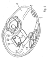
- the ear cup according to the invention has an inner cup portion 1 and an outer cup portion 2.
- the inner cup portion 1 has for its purpose to define an enclosed, noise-damping space 3 which outwardly (upwardly in the Figure) is closed by means of a partition 4.
- the partition 4 has an outside which, in its entirety, is free and readily accessible and which, depending on the embodiment, is intended for mounting of electronics, microphone, loudspeaker, battery or the like. The exact design of those details which is required for such mounting of components forms no germane part of the present invention and, as a result, will not be described in greater detail below. Further, to the extent the partition 4 has any opening, this is small and easy to close and seal.
- the purpose of the outer cup portion 2 is to realise a space for accommodating electronics and/or a current source or the like, in other words such components as may be mounted on the outside of the partition 4.
- the outer cup portion 2 In order to permit simple mounting and access of the components that may be mounted on the outside of the partition 4 of the inner cup portion 1, the outer cup portion 2 is so large that it covers the whole of the outside of the inner cup portion. Otherwise expressed, the outer cup portion 2 extends all the way out to the periphery 5 of the inner cp portion, for which reason the outside of the partition 4 is completely exposed when the outer cup portion 2 is dismounted.
- the outer cup portion 2 For mounting of the outer cup portion 2 on the inner cup portion 1, the outer cup portion 2 has a locking device by means of which the whole of the outer cup portion may be released from the inner cup portion.
- the locking device includes a locking member 6 which, in a guide on the outer cup portion, is movable between a locked position (according to Fig. 1 ) and an open position, which is not shown in Fig. 1 but rather in Fig. 5 .
- the locking device further includes mutually engaging catch means 7 and 8 on the outer cup portion 2 and the inner cup portion 1. These catch means are shown in the left-hand part of Fig. 1 .
- the outer cup portion 1 has an aperture 9 through which the locking member 6 is intended to extend.
- the locking member 6 has, as is most clearly apparent from Figs. 1 , 6 and 8 , an inner shank 10 and an outer shank 11, the inner shank being intended to be located on the inside of the outer cup portion 2, while the outer shank 11 is intended to be located in a guide on the outside of the outer cup portion 2.
- This guide is formed by a depression defined by two opposing walls 12 in the outside of the outer cup portion 2. Both of these walls 12 are intended to abut against opposing side edges 13 and 14 on the outer shank 11 of the locking member 6.
- the locking member will be reciprocally slidable parallel with the double arrow A in Fig. 1 .
- the inner cup portion 1 has a locking recess 15 into which the inner shank 10 is insertable with a locking portion 16.
- the locking member 6 On opening of the locking members, the locking member 6 is displaced in a direction to the right in Fig. 1 so far that the inner shank 10 departs from the locking recess 15. This implies that, in Fig. 1 , the outer cup portion 2 could be lifted upwards and then be displaced in a direction to the left, so that the catch means 7 and 8 release.
- the mounting of the outer cup portion 2 on the inner cup portion takes place in the reverse order.
- Figs. 3 to 5 show the outer cup portion from the inside, and it will be clearly apparent that the locking member in Fig. 3 is located in the open position, while in Fig. 4 it is located in an intermediate position in order, in Fig. 5 , to be located in the locking position.
- the catch means 7 on the inside of the outer cup portion 2 are also clearly apparent.
- the ear cup has no loose small parts that might possibly be lost in the event of careless handling.
- One example of such a small part could be the locking member 6.
- the locking member is provided with retainer means in the form of projections 18 projecting in opposing directions from the in inner shank of the locking member at its locking portion 16. These projections have such an extent beyond the width of the inner shank that this prevents withdrawal of the inner shank through the aperture 9 in the outer cup portion.
- the inner shank has two recesses 19 disposed in opposing edges in conjunction with the projections 18. It will be apparent from Fig. 7 that the depth of the recesses 19 in the width direction of the inner shank is larger than the extent of the projections 18 outside the opposing side edges 13 and 14 of the locking member. This implies that, by a lateral displacement of the locking member transversely of the extent of the walls 12, it is possible to cause a defining edge for the aperture 9 to be located in either of the recesses 19. Since the recess is deeper than the extent of the opposingly located projection 18, the locking member can "be wriggled into the aperture", but also be dismounted therefrom by a reverse movement pattern. In order for this to be possible, it is only necessary that the outer shank 11 is free from the guiding walls 12.
- the outer cup portion 2 has, on its inside and in association with the aperture 9, two depressions 23, one at each short end of the aperture. On lateral displacement of the locking member 6, its one projection 18 will be accommodated in the one depression 23.
- the locking member 6 is manufactured from a resilient material and has, at the free end of the outer shank 11, an inwardly directed bulge 20 which, under the action of the spring forces inherent in the locking member 6, may be snapped into a recess 21 on the outside of the outer cup portion 2 (see Fig. 1 ). In such a snapped-in position, the bulge 20 prevents unintentional displacement of the locking member 6 in the opening direction.
- the inherent resilient force in the locking member 6 also strives to keep the outer shank 11 in the guide 12. This spring force must be overcome before the locking member can be laterally displaced and dismounted.
- the outer cup portion 2 has, in association with its recess 21, a hollow 22 which permits access to the end surface of the outer shank 11 so that this, with the aid of a tool or a human nail, can be lifted out a sufficient distance in order that the bulge 20 will be free from the recess 21 and thereafter the whole of the locking member will be able to be displaced in the opening direction.
Landscapes
- Health & Medical Sciences (AREA)
- Life Sciences & Earth Sciences (AREA)
- Vascular Medicine (AREA)
- Animal Behavior & Ethology (AREA)
- Biophysics (AREA)
- Otolaryngology (AREA)
- Psychology (AREA)
- Engineering & Computer Science (AREA)
- Biomedical Technology (AREA)
- Heart & Thoracic Surgery (AREA)
- Physics & Mathematics (AREA)
- Acoustics & Sound (AREA)
- General Health & Medical Sciences (AREA)
- Public Health (AREA)
- Veterinary Medicine (AREA)
- Buckles (AREA)
- Prostheses (AREA)
- Purses, Travelling Bags, Baskets, Or Suitcases (AREA)
- Food-Manufacturing Devices (AREA)
- Connector Housings Or Holding Contact Members (AREA)
Claims (9)
- Coquille antibruit comprenant : une partie de coquille interne (1) pour former un espace insonorisant (3) et une partie de coquille externe (2) pour former un espace destiné à recevoir des composants électroniques, des connexions électriques et/ou une source de courant, la partie de coquille externe pouvant être fixée sur la partie interne, et un dispositif de verrouillage qui inclut un élément de verrouillage (6) disposé dans un guide (12) dans la partie de coquille externe (2), l'élément de verrouillage étant mobile entre une position verrouillée où la partie de coquille externe est fixée sur la partie interne (1) et une position ouverte où la partie de coquille externe peut être retirée de la partie interne ; l'élément de verrouillage et la partie de coquille externe comportent des moyens de retenue coopérant mutuellement (18) pour retenir fixement l'élément de verrouillage sur la partie de coquille externe également dans la position ouverte ; et la partie de coquille externe (2) couvre l'intégralité de l'extérieur de la partie de coquille interne (1), et des composants électroniques et/ou une source de courant sont montés sur celle-ci.
- Coquille antibruit selon la revendication 1, caractérisée en ce que le guide (12) est disposé pour guider l'élément de verrouillage (6) dans un mouvement de déplacement.
- Coquille antibruit selon la revendication 1 ou 2, caractérisée en ce que le guide (12) est disposé sur l'extérieur de la partie de coquille externe (2).
- Coquille antibruit selon l'une quelconque des revendications 1 à 3, caractérisée en ce que l'élément de verrouillage (6) a une partie de verrouillage (16) sur l'intérieur de la partie de coquille externe (2), la partie de verrouillage, dans la position verrouillée, étant située dans un évidement de verrouillage (15) sur la partie de coquille interne (1).
- Coquille antibruit selon l'une quelconque des revendications 1 à 4, caractérisée en ce que le dispositif de verrouillage inclut en outre des moyens de saisie (7, 8) venant en prise l'un avec l'autre dans la position verrouillée, un sur l'extérieur de la partie de coquille interne et un sur l'intérieur de la partie de coquille externe (2), les moyens de saisie étant libérables l'un de l'autre dans la position ouverte.
- Coquille antibruit selon l'une quelconque des revendications 1 à 5, caractérisée en ce que l'élément de verrouillage (6) a une tige interne (10) à l'intérieur dans la partie de coquille externe (2), et une tige externe (11) sur l'extérieur de celle-ci, l'élément de verrouillage s'étendant à travers une ouverture (9) dans la partie de coquille externe, en ce que les moyens de retenue incluent au moins une saillie (18) qui s'étend latéralement hors de la tige interne de sorte que la largeur de celle-ci au-dessus de la saillie est plus grande que la largeur de l'ouverture.
- Coquille antibruit selon la revendication 6, caractérisée en ce que la tige interne (10) comporte un évidement (19) dans le bord (13, 14) situé en alignement avec la saillie, l'évidement étant d'une profondeur qui est plus grande que l'étendue de dépassement de la saillie (18), moyennant quoi l'élément de verrouillage (6) peut être monté dans et démonté de l'ouverture (9) par un déplacement latéral de l'élément de verrouillage (6) de sorte que le bord de l'ouverture est situé dans l'évidement.
- Coquille antibruit selon la revendication 7, caractérisée en ce que l'élément de verrouillage (6) a deux saillies opposées (18) et deux évidements (19) disposés en association avec celles-ci.
- Coquille antibruit selon l'une quelconque des revendications 1 à 8, caractérisée en ce que l'élément de verrouillage (6) est produit à partir d'un matériau élastique, en ce qu'il comporte une protubérance (20) qui, sous l'action des forces élastiques inhérentes, peut être emboîtée dans un évidement (21) dans la partie de coquille externe (2) afin d'empêcher un déplacement involontaire de l'élément de verrouillage en position ouverte.
Priority Applications (1)
| Application Number | Priority Date | Filing Date | Title |
|---|---|---|---|
| PL06733353T PL1877015T3 (pl) | 2005-04-29 | 2006-04-26 | Muszla słuchawkowa |
Applications Claiming Priority (2)
| Application Number | Priority Date | Filing Date | Title |
|---|---|---|---|
| SE0500982A SE528519C2 (sv) | 2005-04-29 | 2005-04-29 | Hörselkåpa |
| PCT/SE2006/000497 WO2006118515A1 (fr) | 2005-04-29 | 2006-04-26 | Oreillette |
Publications (3)
| Publication Number | Publication Date |
|---|---|
| EP1877015A1 EP1877015A1 (fr) | 2008-01-16 |
| EP1877015A4 EP1877015A4 (fr) | 2013-05-22 |
| EP1877015B1 true EP1877015B1 (fr) | 2015-09-30 |
Family
ID=37308228
Family Applications (1)
| Application Number | Title | Priority Date | Filing Date |
|---|---|---|---|
| EP06733353.4A Active EP1877015B1 (fr) | 2005-04-29 | 2006-04-26 | Oreillette |
Country Status (6)
| Country | Link |
|---|---|
| US (1) | US8189801B2 (fr) |
| EP (1) | EP1877015B1 (fr) |
| CN (1) | CN100542508C (fr) |
| PL (1) | PL1877015T3 (fr) |
| SE (1) | SE528519C2 (fr) |
| WO (1) | WO2006118515A1 (fr) |
Families Citing this family (14)
| Publication number | Priority date | Publication date | Assignee | Title |
|---|---|---|---|---|
| US20050238181A1 (en) * | 2003-11-27 | 2005-10-27 | Sigvard Nilsson | Hearing protector |
| SE526944C2 (sv) | 2003-11-27 | 2005-11-22 | Peltor Ab | Hörselskydd |
| SE528514C2 (sv) | 2005-04-29 | 2006-12-05 | Peltor Ab | Hörselkåpa |
| SE528519C2 (sv) * | 2005-04-29 | 2006-12-05 | Peltor Ab | Hörselkåpa |
| WO2009131518A1 (fr) * | 2008-04-24 | 2009-10-29 | Sperian Hearing Protection, Llc | Oreillette |
| SE531656E5 (sv) * | 2008-05-12 | 2011-04-26 | 3M Svenska Ab | Hörselskydd |
| US9900735B2 (en) | 2015-12-18 | 2018-02-20 | Federal Signal Corporation | Communication systems |
| CN105534644A (zh) * | 2016-02-23 | 2016-05-04 | 徐漫 | 一种双海绵吸水耳罩 |
| USD877422S1 (en) | 2017-10-06 | 2020-03-03 | Galvion Ltd. | Ear cup |
| USD864901S1 (en) * | 2018-05-18 | 2019-10-29 | Gentex Corporation | Headset |
| USD968365S1 (en) * | 2019-10-18 | 2022-11-01 | Jsp Limited | Ear defender |
| EP4319700A1 (fr) * | 2021-04-09 | 2024-02-14 | Tecmen Electronics Co., Ltd. | Protège-oreilles et ensemble protège-oreilles |
| CN112972116A (zh) * | 2021-04-09 | 2021-06-18 | 泰克曼(南京)电子有限公司 | 防护耳罩及其组件 |
| CA214012S (en) * | 2021-11-08 | 2023-05-02 | ODM GmbH | Earcup for headphones |
Citations (2)
| Publication number | Priority date | Publication date | Assignee | Title |
|---|---|---|---|---|
| US2235372A (en) * | 1938-02-22 | 1941-03-18 | Siemens App Und Maschinen Gmbh | Receiver headband |
| US4066849A (en) * | 1976-06-11 | 1978-01-03 | Koss Corporation | Rotary-type control for headphone earpiece |
Family Cites Families (74)
| Publication number | Priority date | Publication date | Assignee | Title |
|---|---|---|---|---|
| DE1204272B (de) * | 1960-02-24 | 1965-11-04 | Louis Ernest Bonnin | Sprachgarnitur |
| US3306991A (en) * | 1963-06-04 | 1967-02-28 | Homer J Wood | Protective hearing aid |
| US3394226A (en) * | 1963-08-19 | 1968-07-23 | Daniel E. Andrews Jr. | Special purpose hearing aid |
| GB1160431A (en) | 1966-05-04 | 1969-08-06 | Mini Of Technology London | Ear Defenders. |
| US3456263A (en) * | 1967-05-09 | 1969-07-22 | Gentex Corp | Rigid shell helmet with ear cup |
| GB1289993A (fr) | 1969-08-07 | 1972-09-20 | ||
| US3579640A (en) * | 1970-02-11 | 1971-05-25 | American Optical Corp | Hearing protector headsets |
| US3890474A (en) * | 1972-05-17 | 1975-06-17 | Raymond C Glicksberg | Sound amplitude limiters |
| AT341009B (de) * | 1972-06-22 | 1978-01-10 | Int Standard Electric Corp | Hor-sprech-garnitur |
| US3833939A (en) * | 1972-11-03 | 1974-09-10 | American Optical Corp | Hearing protector headset |
| US3952158A (en) * | 1974-08-26 | 1976-04-20 | Kyle Gordon L | Ear protection and hearing device |
| US4027113A (en) * | 1974-09-12 | 1977-05-31 | Nippon Gakki Seizo Kabushiki Kaisha | Headphone |
| US4023209A (en) | 1975-12-17 | 1977-05-17 | Gentex Corporation | Protective helmet assembly with segmental outer shell |
| US4064362A (en) | 1976-09-13 | 1977-12-20 | David Richard Williams | Hearing protector |
| US4064653A (en) * | 1976-10-29 | 1977-12-27 | Three Rivers Aluminum Company | Sliding window |
| US4327257A (en) * | 1979-09-10 | 1982-04-27 | Schwartz Leslie H | Alignment device for electro-acoustical transducers |
| US4302635A (en) * | 1980-01-04 | 1981-11-24 | Koss Corporation | Headphone construction |
| JPS5711882U (fr) * | 1980-06-20 | 1982-01-21 | ||
| US4677678A (en) * | 1984-07-10 | 1987-06-30 | The United States Of America As Represented By The Department Of Health And Human Services | Active hearing protectors |
| US4867149A (en) * | 1985-03-29 | 1989-09-19 | Cabot Corporation | Earplugs |
| US4928311A (en) * | 1986-01-03 | 1990-05-22 | Trompler Lyle D | Noise limiting circuit for earmuffs |
| WO1987004065A1 (fr) | 1986-01-03 | 1987-07-16 | Trompler Lyle D | Circuit de limitation du bruit pour des casques de protection auriculaire |
| FR2595498B1 (fr) * | 1986-03-07 | 1989-06-02 | Centre Nat Rech Scient | Procedes et dispositifs pour attenuer les bruits d'origine externe parvenant au tympan et ameliorer l'intelligibilite des communications electro-acoustiques |
| US5181252A (en) * | 1987-12-28 | 1993-01-19 | Bose Corporation | High compliance headphone driving |
| US4985925A (en) * | 1988-06-24 | 1991-01-15 | Sensor Electronics, Inc. | Active noise reduction system |
| US5125032A (en) * | 1988-12-02 | 1992-06-23 | Erwin Meister | Talk/listen headset |
| US4965836A (en) * | 1989-01-19 | 1990-10-23 | Koss Corporation | Stereo headphone |
| DK576889D0 (da) | 1989-11-17 | 1989-11-17 | Per Rubak | Hoerevaern |
| CA2045241C (fr) | 1990-07-13 | 1997-03-25 | Lawrence H. Zuckerman | Casque protecteur a systeme de communication active par la voix a courte ou longue distance |
| US5251263A (en) * | 1992-05-22 | 1993-10-05 | Andrea Electronics Corporation | Adaptive noise cancellation and speech enhancement system and apparatus therefor |
| WO1994000089A1 (fr) * | 1992-06-19 | 1994-01-06 | Joseph Sylvester Chang | Protection antibruit pour les oreilles |
| JP3097340B2 (ja) * | 1992-08-19 | 2000-10-10 | ソニー株式会社 | ヘッドホン装置 |
| FR2695302B1 (fr) | 1992-09-08 | 1994-11-18 | Bolle G R M Ets | Casque anti-bruit à force d'application réglable. |
| JP3154214B2 (ja) * | 1992-09-25 | 2001-04-09 | ソニー株式会社 | ヘッドホン |
| DE69424419T2 (de) | 1993-06-23 | 2001-01-04 | Noise Cancellation Technologies, Inc. | Aktive lärmunterdrückungsanordnung mit variabler verstärkung und verbesserter restlärmmessung |
| US5357585A (en) * | 1993-07-09 | 1994-10-18 | Khyber Technologies Corporation | Headphone assembly |
| US5550923A (en) * | 1994-09-02 | 1996-08-27 | Minnesota Mining And Manufacturing Company | Directional ear device with adaptive bandwidth and gain control |
| US5675658A (en) * | 1995-07-27 | 1997-10-07 | Brittain; Thomas Paige | Active noise reduction headset |
| GB2305063A (en) * | 1995-09-07 | 1997-03-26 | Noise Cancellation Tech | Headset with means to limit cushion compression |
| EP0884974B1 (fr) | 1996-02-08 | 2007-04-18 | Hal Greenberger | Stethoscope a reduction de bruit |
| SE511947C2 (sv) | 1997-08-15 | 1999-12-20 | Peltor Ab | Hörselskydd med regleringsknappar nedsänkta i ena hörselkåpan |
| US7664282B2 (en) * | 1998-11-25 | 2010-02-16 | Insound Medical, Inc. | Sealing retainer for extended wear hearing devices |
| US6704428B1 (en) * | 1999-03-05 | 2004-03-09 | Michael Wurtz | Automatic turn-on and turn-off control for battery-powered headsets |
| JP4103267B2 (ja) * | 1999-10-12 | 2008-06-18 | ソニー株式会社 | ヘッドホン |
| US20020001391A1 (en) * | 2000-03-16 | 2002-01-03 | Resistance Technology, Inc. | Acoustic switch with electronic switching capability |
| US6965581B2 (en) * | 2000-04-14 | 2005-11-15 | Hughes Electronics Corp. | Transceiver in a two-way satellite system |
| US20020003889A1 (en) * | 2000-04-19 | 2002-01-10 | Fischer Addison M. | Headphone device with improved controls and/or removable memory |
| US20010046304A1 (en) * | 2000-04-24 | 2001-11-29 | Rast Rodger H. | System and method for selective control of acoustic isolation in headsets |
| US6631279B2 (en) * | 2000-05-05 | 2003-10-07 | Adrian Rivera | Pneumatic cell phone speaker assembly |
| NO312570B1 (no) | 2000-09-01 | 2002-05-27 | Sintef | Stöybeskyttelse med verifiseringsanordning |
| US6801629B2 (en) * | 2000-12-22 | 2004-10-05 | Sonic Innovations, Inc. | Protective hearing devices with multi-band automatic amplitude control and active noise attenuation |
| DE10117704C2 (de) | 2001-04-09 | 2002-08-01 | Hoergeraete Kind Gmbh U Co Kg | Kapselgehörschützer mit aktiver Schalldruckkompensation |
| US6970571B2 (en) * | 2002-02-02 | 2005-11-29 | Jackson Products, Inc. | Low cost hearing protection device |
| AU2003221710A1 (en) | 2002-04-08 | 2003-10-27 | Adam M. Faussett | Ear protection device |
| US6724906B2 (en) * | 2002-05-07 | 2004-04-20 | Alex Naksen | Adjustable headphone |
| TW547882U (en) * | 2002-12-13 | 2003-08-11 | Chang-Ning Hung | Earphone capable of automatically receiving the earphone wire |
| US20040125976A1 (en) * | 2002-12-30 | 2004-07-01 | Reneker Brian Scott | Headphones or earmuffs with a user operated mechanical device that controls the volume of exterior sound entering the ear of the user |
| US7327850B2 (en) * | 2003-07-15 | 2008-02-05 | Bose Corporation | Supplying electrical power |
| DE20312514U1 (de) | 2003-08-12 | 2003-11-13 | Agostino, Bruno, 50677 Köln | Variabler Gehörschutz |
| US8054985B2 (en) * | 2003-11-03 | 2011-11-08 | 3M Innovative Properties Company | Low sound attenuating hearing protection device with filter arrangement |
| SE526944C2 (sv) * | 2003-11-27 | 2005-11-22 | Peltor Ab | Hörselskydd |
| US7099485B2 (en) * | 2004-03-10 | 2006-08-29 | Phonak Ag | Housing for hearing devices or hearing aids |
| US7245735B2 (en) * | 2004-04-02 | 2007-07-17 | David Han | Earmuff structure for headset or ear protector |
| US7308106B2 (en) * | 2004-05-17 | 2007-12-11 | Adaptive Technologies, Inc. | System and method for optimized active controller design in an ANR system |
| EP1629808A1 (fr) | 2004-08-25 | 2006-03-01 | Phonak Ag | Bouchon d'oreille et son procédé de fabrication |
| US7391878B2 (en) * | 2005-01-12 | 2008-06-24 | Sheng-Hsin Liao | Earphone device having composite functions |
| EP1865745A4 (fr) * | 2005-04-01 | 2011-03-30 | Panasonic Corp | Combine, dispositif electronique et dispositif de communication |
| SE528519C2 (sv) * | 2005-04-29 | 2006-12-05 | Peltor Ab | Hörselkåpa |
| SE528514C2 (sv) | 2005-04-29 | 2006-12-05 | Peltor Ab | Hörselkåpa |
| GB2443989B (en) * | 2005-11-26 | 2008-11-05 | Wolfson Microelectronics Plc | Audio device and method |
| US7574917B2 (en) * | 2006-07-13 | 2009-08-18 | Phonak Ag | Method for in-situ measuring of acoustic attenuation and system therefor |
| GB2445984B (en) | 2007-01-25 | 2011-12-07 | Sonaptic Ltd | Ambient noise reduction |
| GB2445388B (en) | 2007-02-16 | 2009-01-07 | Sonaptic Ltd | Ear-worn speaker-carrying devices |
| DE102007013719B4 (de) | 2007-03-19 | 2015-10-29 | Sennheiser Electronic Gmbh & Co. Kg | Hörer |
-
2005
- 2005-04-29 SE SE0500982A patent/SE528519C2/sv unknown
-
2006
- 2006-04-26 WO PCT/SE2006/000497 patent/WO2006118515A1/fr active Application Filing
- 2006-04-26 PL PL06733353T patent/PL1877015T3/pl unknown
- 2006-04-26 CN CNB2006800147086A patent/CN100542508C/zh not_active Expired - Fee Related
- 2006-04-26 EP EP06733353.4A patent/EP1877015B1/fr active Active
- 2006-04-26 US US11/912,434 patent/US8189801B2/en active Active
Patent Citations (2)
| Publication number | Priority date | Publication date | Assignee | Title |
|---|---|---|---|---|
| US2235372A (en) * | 1938-02-22 | 1941-03-18 | Siemens App Und Maschinen Gmbh | Receiver headband |
| US4066849A (en) * | 1976-06-11 | 1978-01-03 | Koss Corporation | Rotary-type control for headphone earpiece |
Also Published As
| Publication number | Publication date |
|---|---|
| EP1877015A1 (fr) | 2008-01-16 |
| EP1877015A4 (fr) | 2013-05-22 |
| SE528519C2 (sv) | 2006-12-05 |
| PL1877015T3 (pl) | 2016-05-31 |
| CN101166489A (zh) | 2008-04-23 |
| WO2006118515A1 (fr) | 2006-11-09 |
| US8189801B2 (en) | 2012-05-29 |
| CN100542508C (zh) | 2009-09-23 |
| US20080192973A1 (en) | 2008-08-14 |
| SE0500982L (sv) | 2006-10-30 |
Similar Documents
| Publication | Publication Date | Title |
|---|---|---|
| EP1877015B1 (fr) | Oreillette | |
| EP3254075B1 (fr) | Serre-tête confortable amélioré pour protection auditive | |
| EP1355508B1 (fr) | Embout auriculaire pour la rétention améliorée d'un dispositif accouplé | |
| AU2022209238B2 (en) | Headset and headset coupling system | |
| EP0637896B1 (fr) | Dispositif d'écouteur | |
| US8695798B2 (en) | Case for electronic devices | |
| US20060212998A1 (en) | Ear protector for helmet, helmet and method for protecting ears | |
| US10104929B2 (en) | Helmet with externally positionable internal ear cups | |
| WO2007095572A3 (fr) | Support d'ecouteurs de type boutons | |
| CA2443580A1 (fr) | Coquille antibruit comportant un ecouteur | |
| CN214967652U (zh) | 防护耳罩及其组件 | |
| US20210128067A1 (en) | Enclosure | |
| US20120031404A1 (en) | Mask | |
| WO2014152698A1 (fr) | Dispositif de rangement d'écouteurs | |
| JP2007124022A (ja) | 補聴器 | |
| EP3169084B1 (fr) | Dispositif auditif comprenant un tiroir de batterie | |
| EP1838134B1 (fr) | Dispositif audio de type intra-auriculaire et méthode de fixation d'un module électronique dans une cavité d'un boîtier personnalisé pour un dispositif audio de type intra-auriculaire | |
| KR20150004606U (ko) | 휴대용 단말기 보호 및 수납 케이스 | |
| EP1968344A1 (fr) | Écouteur avec espace d'expansion dans chaque récepteur | |
| EP3945727B1 (fr) | Dispositif de communication sans fil avec un support pouvant être fixé à une sangle de casque | |
| GB2588327A (en) | Enclosure | |
| WO2000072632A3 (fr) | Dispositif combine de suspension de recepteur et de protection contre le cerumen pour prothese auditive dans le canal | |
| JP2007312343A (ja) | 送受話器保持具用ヘッドセット | |
| KR20140065737A (ko) | 이어폰 수납이 가능한 모바일 디바이스 케이스 | |
| KR20140065738A (ko) | 이어폰 수납이 가능한 모바일 디바이스 케이스 |
Legal Events
| Date | Code | Title | Description |
|---|---|---|---|
| PUAI | Public reference made under article 153(3) epc to a published international application that has entered the european phase |
Free format text: ORIGINAL CODE: 0009012 |
|
| 17P | Request for examination filed |
Effective date: 20071129 |
|
| AK | Designated contracting states |
Kind code of ref document: A1 Designated state(s): AT BE BG CH CY CZ DE DK EE ES FI FR GB GR HU IE IS IT LI LT LU LV MC NL PL PT RO SE SI SK TR |
|
| DAX | Request for extension of the european patent (deleted) | ||
| RAP1 | Party data changed (applicant data changed or rights of an application transferred) |
Owner name: 3M SVENSKA AKTIEBOLAG |
|
| A4 | Supplementary search report drawn up and despatched |
Effective date: 20130419 |
|
| RIC1 | Information provided on ipc code assigned before grant |
Ipc: A61F 11/14 20060101AFI20130415BHEP Ipc: H04R 1/10 20060101ALI20130415BHEP |
|
| 17Q | First examination report despatched |
Effective date: 20131212 |
|
| GRAP | Despatch of communication of intention to grant a patent |
Free format text: ORIGINAL CODE: EPIDOSNIGR1 |
|
| INTG | Intention to grant announced |
Effective date: 20150430 |
|
| GRAS | Grant fee paid |
Free format text: ORIGINAL CODE: EPIDOSNIGR3 |
|
| GRAA | (expected) grant |
Free format text: ORIGINAL CODE: 0009210 |
|
| AK | Designated contracting states |
Kind code of ref document: B1 Designated state(s): AT BE BG CH CY CZ DE DK EE ES FI FR GB GR HU IE IS IT LI LT LU LV MC NL PL PT RO SE SI SK TR |
|
| REG | Reference to a national code |
Ref country code: CH Ref legal event code: EP Ref country code: GB Ref legal event code: FG4D |
|
| REG | Reference to a national code |
Ref country code: AT Ref legal event code: REF Ref document number: 751944 Country of ref document: AT Kind code of ref document: T Effective date: 20151015 |
|
| REG | Reference to a national code |
Ref country code: IE Ref legal event code: FG4D |
|
| REG | Reference to a national code |
Ref country code: DE Ref legal event code: R096 Ref document number: 602006046807 Country of ref document: DE |
|
| PG25 | Lapsed in a contracting state [announced via postgrant information from national office to epo] |
Ref country code: LT Free format text: LAPSE BECAUSE OF FAILURE TO SUBMIT A TRANSLATION OF THE DESCRIPTION OR TO PAY THE FEE WITHIN THE PRESCRIBED TIME-LIMIT Effective date: 20150930 Ref country code: FI Free format text: LAPSE BECAUSE OF FAILURE TO SUBMIT A TRANSLATION OF THE DESCRIPTION OR TO PAY THE FEE WITHIN THE PRESCRIBED TIME-LIMIT Effective date: 20150930 Ref country code: GR Free format text: LAPSE BECAUSE OF FAILURE TO SUBMIT A TRANSLATION OF THE DESCRIPTION OR TO PAY THE FEE WITHIN THE PRESCRIBED TIME-LIMIT Effective date: 20151231 Ref country code: LV Free format text: LAPSE BECAUSE OF FAILURE TO SUBMIT A TRANSLATION OF THE DESCRIPTION OR TO PAY THE FEE WITHIN THE PRESCRIBED TIME-LIMIT Effective date: 20150930 |
|
| REG | Reference to a national code |
Ref country code: NL Ref legal event code: MP Effective date: 20150930 |
|
| REG | Reference to a national code |
Ref country code: LT Ref legal event code: MG4D |
|
| REG | Reference to a national code |
Ref country code: AT Ref legal event code: MK05 Ref document number: 751944 Country of ref document: AT Kind code of ref document: T Effective date: 20150930 |
|
| PG25 | Lapsed in a contracting state [announced via postgrant information from national office to epo] |
Ref country code: SE Free format text: LAPSE BECAUSE OF FAILURE TO SUBMIT A TRANSLATION OF THE DESCRIPTION OR TO PAY THE FEE WITHIN THE PRESCRIBED TIME-LIMIT Effective date: 20150930 |
|
| REG | Reference to a national code |
Ref country code: FR Ref legal event code: PLFP Year of fee payment: 11 |
|
| PG25 | Lapsed in a contracting state [announced via postgrant information from national office to epo] |
Ref country code: IS Free format text: LAPSE BECAUSE OF FAILURE TO SUBMIT A TRANSLATION OF THE DESCRIPTION OR TO PAY THE FEE WITHIN THE PRESCRIBED TIME-LIMIT Effective date: 20160130 Ref country code: SK Free format text: LAPSE BECAUSE OF FAILURE TO SUBMIT A TRANSLATION OF THE DESCRIPTION OR TO PAY THE FEE WITHIN THE PRESCRIBED TIME-LIMIT Effective date: 20150930 Ref country code: CZ Free format text: LAPSE BECAUSE OF FAILURE TO SUBMIT A TRANSLATION OF THE DESCRIPTION OR TO PAY THE FEE WITHIN THE PRESCRIBED TIME-LIMIT Effective date: 20150930 Ref country code: EE Free format text: LAPSE BECAUSE OF FAILURE TO SUBMIT A TRANSLATION OF THE DESCRIPTION OR TO PAY THE FEE WITHIN THE PRESCRIBED TIME-LIMIT Effective date: 20150930 Ref country code: ES Free format text: LAPSE BECAUSE OF FAILURE TO SUBMIT A TRANSLATION OF THE DESCRIPTION OR TO PAY THE FEE WITHIN THE PRESCRIBED TIME-LIMIT Effective date: 20150930 Ref country code: IT Free format text: LAPSE BECAUSE OF FAILURE TO SUBMIT A TRANSLATION OF THE DESCRIPTION OR TO PAY THE FEE WITHIN THE PRESCRIBED TIME-LIMIT Effective date: 20150930 Ref country code: NL Free format text: LAPSE BECAUSE OF FAILURE TO SUBMIT A TRANSLATION OF THE DESCRIPTION OR TO PAY THE FEE WITHIN THE PRESCRIBED TIME-LIMIT Effective date: 20150930 |
|
| PG25 | Lapsed in a contracting state [announced via postgrant information from national office to epo] |
Ref country code: RO Free format text: LAPSE BECAUSE OF FAILURE TO SUBMIT A TRANSLATION OF THE DESCRIPTION OR TO PAY THE FEE WITHIN THE PRESCRIBED TIME-LIMIT Effective date: 20150930 Ref country code: PT Free format text: LAPSE BECAUSE OF FAILURE TO SUBMIT A TRANSLATION OF THE DESCRIPTION OR TO PAY THE FEE WITHIN THE PRESCRIBED TIME-LIMIT Effective date: 20160201 Ref country code: AT Free format text: LAPSE BECAUSE OF FAILURE TO SUBMIT A TRANSLATION OF THE DESCRIPTION OR TO PAY THE FEE WITHIN THE PRESCRIBED TIME-LIMIT Effective date: 20150930 |
|
| REG | Reference to a national code |
Ref country code: DE Ref legal event code: R097 Ref document number: 602006046807 Country of ref document: DE |
|
| PLBE | No opposition filed within time limit |
Free format text: ORIGINAL CODE: 0009261 |
|
| STAA | Information on the status of an ep patent application or granted ep patent |
Free format text: STATUS: NO OPPOSITION FILED WITHIN TIME LIMIT |
|
| PG25 | Lapsed in a contracting state [announced via postgrant information from national office to epo] |
Ref country code: BE Free format text: LAPSE BECAUSE OF NON-PAYMENT OF DUE FEES Effective date: 20160430 Ref country code: DK Free format text: LAPSE BECAUSE OF FAILURE TO SUBMIT A TRANSLATION OF THE DESCRIPTION OR TO PAY THE FEE WITHIN THE PRESCRIBED TIME-LIMIT Effective date: 20150930 |
|
| 26N | No opposition filed |
Effective date: 20160701 |
|
| PG25 | Lapsed in a contracting state [announced via postgrant information from national office to epo] |
Ref country code: SI Free format text: LAPSE BECAUSE OF FAILURE TO SUBMIT A TRANSLATION OF THE DESCRIPTION OR TO PAY THE FEE WITHIN THE PRESCRIBED TIME-LIMIT Effective date: 20150930 |
|
| REG | Reference to a national code |
Ref country code: CH Ref legal event code: PL |
|
| REG | Reference to a national code |
Ref country code: DE Ref legal event code: R082 Ref document number: 602006046807 Country of ref document: DE Representative=s name: ISARPATENT - PATENT- UND RECHTSANWAELTE BEHNIS, DE Ref country code: DE Ref legal event code: R082 Ref document number: 602006046807 Country of ref document: DE Representative=s name: ISARPATENT - PATENT- UND RECHTSANWAELTE BARTH , DE Ref country code: DE Ref legal event code: R081 Ref document number: 602006046807 Country of ref document: DE Owner name: 3M INNOVATIVE PROPERTIES COMPANY, SAINT PAUL, US Free format text: FORMER OWNER: 3M SVENSKA AKTIEBOLAG, SOLLENTUNA, SE Ref country code: DE Ref legal event code: R082 Ref document number: 602006046807 Country of ref document: DE Representative=s name: ISARPATENT - PATENTANWAELTE- UND RECHTSANWAELT, DE |
|
| PG25 | Lapsed in a contracting state [announced via postgrant information from national office to epo] |
Ref country code: LU Free format text: LAPSE BECAUSE OF FAILURE TO SUBMIT A TRANSLATION OF THE DESCRIPTION OR TO PAY THE FEE WITHIN THE PRESCRIBED TIME-LIMIT Effective date: 20160426 Ref country code: BE Free format text: LAPSE BECAUSE OF FAILURE TO SUBMIT A TRANSLATION OF THE DESCRIPTION OR TO PAY THE FEE WITHIN THE PRESCRIBED TIME-LIMIT Effective date: 20150930 |
|
| REG | Reference to a national code |
Ref country code: IE Ref legal event code: MM4A |
|
| PG25 | Lapsed in a contracting state [announced via postgrant information from national office to epo] |
Ref country code: LI Free format text: LAPSE BECAUSE OF NON-PAYMENT OF DUE FEES Effective date: 20160430 Ref country code: CH Free format text: LAPSE BECAUSE OF NON-PAYMENT OF DUE FEES Effective date: 20160430 |
|
| REG | Reference to a national code |
Ref country code: GB Ref legal event code: 732E Free format text: REGISTERED BETWEEN 20170202 AND 20170208 |
|
| REG | Reference to a national code |
Ref country code: FR Ref legal event code: PLFP Year of fee payment: 12 |
|
| PG25 | Lapsed in a contracting state [announced via postgrant information from national office to epo] |
Ref country code: IE Free format text: LAPSE BECAUSE OF NON-PAYMENT OF DUE FEES Effective date: 20160426 |
|
| REG | Reference to a national code |
Ref country code: FR Ref legal event code: TP Owner name: 3M INNOVATIVE PROPERTIES CO., US Effective date: 20170512 |
|
| REG | Reference to a national code |
Ref country code: FR Ref legal event code: PLFP Year of fee payment: 13 |
|
| PG25 | Lapsed in a contracting state [announced via postgrant information from national office to epo] |
Ref country code: CY Free format text: LAPSE BECAUSE OF FAILURE TO SUBMIT A TRANSLATION OF THE DESCRIPTION OR TO PAY THE FEE WITHIN THE PRESCRIBED TIME-LIMIT Effective date: 20150930 Ref country code: HU Free format text: LAPSE BECAUSE OF FAILURE TO SUBMIT A TRANSLATION OF THE DESCRIPTION OR TO PAY THE FEE WITHIN THE PRESCRIBED TIME-LIMIT; INVALID AB INITIO Effective date: 20060426 |
|
| PG25 | Lapsed in a contracting state [announced via postgrant information from national office to epo] |
Ref country code: MC Free format text: LAPSE BECAUSE OF FAILURE TO SUBMIT A TRANSLATION OF THE DESCRIPTION OR TO PAY THE FEE WITHIN THE PRESCRIBED TIME-LIMIT Effective date: 20150930 |
|
| PG25 | Lapsed in a contracting state [announced via postgrant information from national office to epo] |
Ref country code: BG Free format text: LAPSE BECAUSE OF FAILURE TO SUBMIT A TRANSLATION OF THE DESCRIPTION OR TO PAY THE FEE WITHIN THE PRESCRIBED TIME-LIMIT Effective date: 20150930 |
|
| PGFP | Annual fee paid to national office [announced via postgrant information from national office to epo] |
Ref country code: TR Payment date: 20190410 Year of fee payment: 14 |
|
| PG25 | Lapsed in a contracting state [announced via postgrant information from national office to epo] |
Ref country code: TR Free format text: LAPSE BECAUSE OF NON-PAYMENT OF DUE FEES Effective date: 20200426 |
|
| P01 | Opt-out of the competence of the unified patent court (upc) registered |
Effective date: 20230530 |
|
| PGFP | Annual fee paid to national office [announced via postgrant information from national office to epo] |
Ref country code: GB Payment date: 20240320 Year of fee payment: 19 |
|
| PGFP | Annual fee paid to national office [announced via postgrant information from national office to epo] |
Ref country code: PL Payment date: 20240323 Year of fee payment: 19 Ref country code: FR Payment date: 20240320 Year of fee payment: 19 |
|
| PGFP | Annual fee paid to national office [announced via postgrant information from national office to epo] |
Ref country code: DE Payment date: 20240320 Year of fee payment: 19 |