EP1876510A2 - Method for controlling and system for charging a battery power supply unit - Google Patents
Method for controlling and system for charging a battery power supply unit Download PDFInfo
- Publication number
- EP1876510A2 EP1876510A2 EP07012164A EP07012164A EP1876510A2 EP 1876510 A2 EP1876510 A2 EP 1876510A2 EP 07012164 A EP07012164 A EP 07012164A EP 07012164 A EP07012164 A EP 07012164A EP 1876510 A2 EP1876510 A2 EP 1876510A2
- Authority
- EP
- European Patent Office
- Prior art keywords
- power supply
- supply unit
- temperature
- heating element
- casing
- Prior art date
- Legal status (The legal status is an assumption and is not a legal conclusion. Google has not performed a legal analysis and makes no representation as to the accuracy of the status listed.)
- Withdrawn
Links
Images


Classifications
-
- B—PERFORMING OPERATIONS; TRANSPORTING
- B60—VEHICLES IN GENERAL
- B60L—PROPULSION OF ELECTRICALLY-PROPELLED VEHICLES; SUPPLYING ELECTRIC POWER FOR AUXILIARY EQUIPMENT OF ELECTRICALLY-PROPELLED VEHICLES; ELECTRODYNAMIC BRAKE SYSTEMS FOR VEHICLES IN GENERAL; MAGNETIC SUSPENSION OR LEVITATION FOR VEHICLES; MONITORING OPERATING VARIABLES OF ELECTRICALLY-PROPELLED VEHICLES; ELECTRIC SAFETY DEVICES FOR ELECTRICALLY-PROPELLED VEHICLES
- B60L1/00—Supplying electric power to auxiliary equipment of vehicles
- B60L1/02—Supplying electric power to auxiliary equipment of vehicles to electric heating circuits
- B60L1/04—Supplying electric power to auxiliary equipment of vehicles to electric heating circuits fed by the power supply line
- B60L1/06—Supplying electric power to auxiliary equipment of vehicles to electric heating circuits fed by the power supply line using only one supply
- B60L1/08—Methods and devices for control or regulation
-
- B—PERFORMING OPERATIONS; TRANSPORTING
- B60—VEHICLES IN GENERAL
- B60L—PROPULSION OF ELECTRICALLY-PROPELLED VEHICLES; SUPPLYING ELECTRIC POWER FOR AUXILIARY EQUIPMENT OF ELECTRICALLY-PROPELLED VEHICLES; ELECTRODYNAMIC BRAKE SYSTEMS FOR VEHICLES IN GENERAL; MAGNETIC SUSPENSION OR LEVITATION FOR VEHICLES; MONITORING OPERATING VARIABLES OF ELECTRICALLY-PROPELLED VEHICLES; ELECTRIC SAFETY DEVICES FOR ELECTRICALLY-PROPELLED VEHICLES
- B60L50/00—Electric propulsion with power supplied within the vehicle
- B60L50/50—Electric propulsion with power supplied within the vehicle using propulsion power supplied by batteries or fuel cells
-
- B—PERFORMING OPERATIONS; TRANSPORTING
- B60—VEHICLES IN GENERAL
- B60L—PROPULSION OF ELECTRICALLY-PROPELLED VEHICLES; SUPPLYING ELECTRIC POWER FOR AUXILIARY EQUIPMENT OF ELECTRICALLY-PROPELLED VEHICLES; ELECTRODYNAMIC BRAKE SYSTEMS FOR VEHICLES IN GENERAL; MAGNETIC SUSPENSION OR LEVITATION FOR VEHICLES; MONITORING OPERATING VARIABLES OF ELECTRICALLY-PROPELLED VEHICLES; ELECTRIC SAFETY DEVICES FOR ELECTRICALLY-PROPELLED VEHICLES
- B60L50/00—Electric propulsion with power supplied within the vehicle
- B60L50/50—Electric propulsion with power supplied within the vehicle using propulsion power supplied by batteries or fuel cells
- B60L50/60—Electric propulsion with power supplied within the vehicle using propulsion power supplied by batteries or fuel cells using power supplied by batteries
- B60L50/64—Constructional details of batteries specially adapted for electric vehicles
-
- B—PERFORMING OPERATIONS; TRANSPORTING
- B60—VEHICLES IN GENERAL
- B60L—PROPULSION OF ELECTRICALLY-PROPELLED VEHICLES; SUPPLYING ELECTRIC POWER FOR AUXILIARY EQUIPMENT OF ELECTRICALLY-PROPELLED VEHICLES; ELECTRODYNAMIC BRAKE SYSTEMS FOR VEHICLES IN GENERAL; MAGNETIC SUSPENSION OR LEVITATION FOR VEHICLES; MONITORING OPERATING VARIABLES OF ELECTRICALLY-PROPELLED VEHICLES; ELECTRIC SAFETY DEVICES FOR ELECTRICALLY-PROPELLED VEHICLES
- B60L58/00—Methods or circuit arrangements for monitoring or controlling batteries or fuel cells, specially adapted for electric vehicles
- B60L58/10—Methods or circuit arrangements for monitoring or controlling batteries or fuel cells, specially adapted for electric vehicles for monitoring or controlling batteries
- B60L58/18—Methods or circuit arrangements for monitoring or controlling batteries or fuel cells, specially adapted for electric vehicles for monitoring or controlling batteries of two or more battery modules
- B60L58/21—Methods or circuit arrangements for monitoring or controlling batteries or fuel cells, specially adapted for electric vehicles for monitoring or controlling batteries of two or more battery modules having the same nominal voltage
-
- B—PERFORMING OPERATIONS; TRANSPORTING
- B60—VEHICLES IN GENERAL
- B60L—PROPULSION OF ELECTRICALLY-PROPELLED VEHICLES; SUPPLYING ELECTRIC POWER FOR AUXILIARY EQUIPMENT OF ELECTRICALLY-PROPELLED VEHICLES; ELECTRODYNAMIC BRAKE SYSTEMS FOR VEHICLES IN GENERAL; MAGNETIC SUSPENSION OR LEVITATION FOR VEHICLES; MONITORING OPERATING VARIABLES OF ELECTRICALLY-PROPELLED VEHICLES; ELECTRIC SAFETY DEVICES FOR ELECTRICALLY-PROPELLED VEHICLES
- B60L58/00—Methods or circuit arrangements for monitoring or controlling batteries or fuel cells, specially adapted for electric vehicles
- B60L58/10—Methods or circuit arrangements for monitoring or controlling batteries or fuel cells, specially adapted for electric vehicles for monitoring or controlling batteries
- B60L58/24—Methods or circuit arrangements for monitoring or controlling batteries or fuel cells, specially adapted for electric vehicles for monitoring or controlling batteries for controlling the temperature of batteries
- B60L58/27—Methods or circuit arrangements for monitoring or controlling batteries or fuel cells, specially adapted for electric vehicles for monitoring or controlling batteries for controlling the temperature of batteries by heating
-
- H—ELECTRICITY
- H02—GENERATION; CONVERSION OR DISTRIBUTION OF ELECTRIC POWER
- H02J—ELECTRIC POWER NETWORKS; CIRCUIT ARRANGEMENTS OR SYSTEMS FOR SUPPLYING OR DISTRIBUTING ELECTRIC POWER; SYSTEMS FOR STORING ELECTRIC ENERGY
- H02J7/00—Circuit arrangements for charging or discharging batteries or for supplying loads from batteries
- H02J7/14—Circuit arrangements for charging or discharging batteries or for supplying loads from batteries for charging batteries from dynamo-electric generators driven at varying speed, e.g. on vehicle
- H02J7/1407—Circuit arrangements for charging or discharging batteries or for supplying loads from batteries for charging batteries from dynamo-electric generators driven at varying speed, e.g. on vehicle on vehicles not being driven by a motor, e.g. bicycles
-
- B—PERFORMING OPERATIONS; TRANSPORTING
- B60—VEHICLES IN GENERAL
- B60L—PROPULSION OF ELECTRICALLY-PROPELLED VEHICLES; SUPPLYING ELECTRIC POWER FOR AUXILIARY EQUIPMENT OF ELECTRICALLY-PROPELLED VEHICLES; ELECTRODYNAMIC BRAKE SYSTEMS FOR VEHICLES IN GENERAL; MAGNETIC SUSPENSION OR LEVITATION FOR VEHICLES; MONITORING OPERATING VARIABLES OF ELECTRICALLY-PROPELLED VEHICLES; ELECTRIC SAFETY DEVICES FOR ELECTRICALLY-PROPELLED VEHICLES
- B60L2240/00—Control parameters of input or output; Target parameters
- B60L2240/40—Drive Train control parameters
- B60L2240/54—Drive Train control parameters related to batteries
- B60L2240/545—Temperature
-
- B—PERFORMING OPERATIONS; TRANSPORTING
- B60—VEHICLES IN GENERAL
- B60L—PROPULSION OF ELECTRICALLY-PROPELLED VEHICLES; SUPPLYING ELECTRIC POWER FOR AUXILIARY EQUIPMENT OF ELECTRICALLY-PROPELLED VEHICLES; ELECTRODYNAMIC BRAKE SYSTEMS FOR VEHICLES IN GENERAL; MAGNETIC SUSPENSION OR LEVITATION FOR VEHICLES; MONITORING OPERATING VARIABLES OF ELECTRICALLY-PROPELLED VEHICLES; ELECTRIC SAFETY DEVICES FOR ELECTRICALLY-PROPELLED VEHICLES
- B60L2240/00—Control parameters of input or output; Target parameters
- B60L2240/40—Drive Train control parameters
- B60L2240/54—Drive Train control parameters related to batteries
- B60L2240/549—Current
-
- B—PERFORMING OPERATIONS; TRANSPORTING
- B60—VEHICLES IN GENERAL
- B60L—PROPULSION OF ELECTRICALLY-PROPELLED VEHICLES; SUPPLYING ELECTRIC POWER FOR AUXILIARY EQUIPMENT OF ELECTRICALLY-PROPELLED VEHICLES; ELECTRODYNAMIC BRAKE SYSTEMS FOR VEHICLES IN GENERAL; MAGNETIC SUSPENSION OR LEVITATION FOR VEHICLES; MONITORING OPERATING VARIABLES OF ELECTRICALLY-PROPELLED VEHICLES; ELECTRIC SAFETY DEVICES FOR ELECTRICALLY-PROPELLED VEHICLES
- B60L2240/00—Control parameters of input or output; Target parameters
- B60L2240/60—Navigation input
- B60L2240/66—Ambient conditions
- B60L2240/662—Temperature
-
- Y—GENERAL TAGGING OF NEW TECHNOLOGICAL DEVELOPMENTS; GENERAL TAGGING OF CROSS-SECTIONAL TECHNOLOGIES SPANNING OVER SEVERAL SECTIONS OF THE IPC; TECHNICAL SUBJECTS COVERED BY FORMER USPC CROSS-REFERENCE ART COLLECTIONS [XRACs] AND DIGESTS
- Y02—TECHNOLOGIES OR APPLICATIONS FOR MITIGATION OR ADAPTATION AGAINST CLIMATE CHANGE
- Y02T—CLIMATE CHANGE MITIGATION TECHNOLOGIES RELATED TO TRANSPORTATION
- Y02T10/00—Road transport of goods or passengers
- Y02T10/60—Other road transportation technologies with climate change mitigation effect
- Y02T10/70—Energy storage systems for electromobility, e.g. batteries
-
- Y—GENERAL TAGGING OF NEW TECHNOLOGICAL DEVELOPMENTS; GENERAL TAGGING OF CROSS-SECTIONAL TECHNOLOGIES SPANNING OVER SEVERAL SECTIONS OF THE IPC; TECHNICAL SUBJECTS COVERED BY FORMER USPC CROSS-REFERENCE ART COLLECTIONS [XRACs] AND DIGESTS
- Y02—TECHNOLOGIES OR APPLICATIONS FOR MITIGATION OR ADAPTATION AGAINST CLIMATE CHANGE
- Y02T—CLIMATE CHANGE MITIGATION TECHNOLOGIES RELATED TO TRANSPORTATION
- Y02T10/00—Road transport of goods or passengers
- Y02T10/60—Other road transportation technologies with climate change mitigation effect
- Y02T10/7072—Electromobility specific charging systems or methods for batteries, ultracapacitors, supercapacitors or double-layer capacitors
-
- Y—GENERAL TAGGING OF NEW TECHNOLOGICAL DEVELOPMENTS; GENERAL TAGGING OF CROSS-SECTIONAL TECHNOLOGIES SPANNING OVER SEVERAL SECTIONS OF THE IPC; TECHNICAL SUBJECTS COVERED BY FORMER USPC CROSS-REFERENCE ART COLLECTIONS [XRACs] AND DIGESTS
- Y02—TECHNOLOGIES OR APPLICATIONS FOR MITIGATION OR ADAPTATION AGAINST CLIMATE CHANGE
- Y02T—CLIMATE CHANGE MITIGATION TECHNOLOGIES RELATED TO TRANSPORTATION
- Y02T10/00—Road transport of goods or passengers
- Y02T10/60—Other road transportation technologies with climate change mitigation effect
- Y02T10/72—Electric energy management in electromobility
-
- Y—GENERAL TAGGING OF NEW TECHNOLOGICAL DEVELOPMENTS; GENERAL TAGGING OF CROSS-SECTIONAL TECHNOLOGIES SPANNING OVER SEVERAL SECTIONS OF THE IPC; TECHNICAL SUBJECTS COVERED BY FORMER USPC CROSS-REFERENCE ART COLLECTIONS [XRACs] AND DIGESTS
- Y02—TECHNOLOGIES OR APPLICATIONS FOR MITIGATION OR ADAPTATION AGAINST CLIMATE CHANGE
- Y02T—CLIMATE CHANGE MITIGATION TECHNOLOGIES RELATED TO TRANSPORTATION
- Y02T90/00—Enabling technologies or technologies with a potential or indirect contribution to GHG emissions mitigation
- Y02T90/10—Technologies relating to charging of electric vehicles
- Y02T90/14—Plug-in electric vehicles
-
- Y—GENERAL TAGGING OF NEW TECHNOLOGICAL DEVELOPMENTS; GENERAL TAGGING OF CROSS-SECTIONAL TECHNOLOGIES SPANNING OVER SEVERAL SECTIONS OF THE IPC; TECHNICAL SUBJECTS COVERED BY FORMER USPC CROSS-REFERENCE ART COLLECTIONS [XRACs] AND DIGESTS
- Y02—TECHNOLOGIES OR APPLICATIONS FOR MITIGATION OR ADAPTATION AGAINST CLIMATE CHANGE
- Y02T—CLIMATE CHANGE MITIGATION TECHNOLOGIES RELATED TO TRANSPORTATION
- Y02T90/00—Enabling technologies or technologies with a potential or indirect contribution to GHG emissions mitigation
- Y02T90/10—Technologies relating to charging of electric vehicles
- Y02T90/16—Information or communication technologies improving the operation of electric vehicles
Definitions
- the charging of the battery at a temperature outside of a given closed characteristic temperature range -not necessarily coinciding with and usually more limited than the closed operating temperature range of the battery - can lead to the battery itself being damaged.
- said power supply unit comprises at least two batteries and at least one heating element is thermally associated with each battery.
- said heating element is of the resistive type, more preferably said heating element comprises at least one resistive sheet applied to at least one battery of said power supply unit, and even more preferably said at least one resistive sheet is interposed between two adjacent batteries of said power supply unit.
- said at least one heating element can be housed in said first casing and come into thermal contact with said power supply unit when the first casing and the second casing are connected, namely during charging.
- the heating element 5 and/or the temperature sensor 6 can be part of the battery charger 1 and come into thermal contact with the power supply unit 4 when connected to the battery charger 1, namely during charging.
- the power regulator 11 preferably consists of a MOSFET, but in different embodiments such a power regulator could, for example, consist of a transistor or even a relay.
- a first embodiment of the method according to the invention shall be described with reference to figure 5 and to the system of one of the embodiments described above.
Landscapes
- Engineering & Computer Science (AREA)
- Power Engineering (AREA)
- Transportation (AREA)
- Mechanical Engineering (AREA)
- Life Sciences & Earth Sciences (AREA)
- Sustainable Development (AREA)
- Sustainable Energy (AREA)
- Secondary Cells (AREA)
- Charge And Discharge Circuits For Batteries Or The Like (AREA)
Abstract
Description
- The present invention relates to a method for controlling and a system for charging a battery power supply unit, in particular for supplying power to electronic devices mounted on bicycles.
- Electronic devices mounted on bicycles, for example for controlling the electronic gearshift and/or for acquiring, displaying and controlling riding parameters and various functions, provide for the use of a power supply unit.
- The power supply unit typically consists of one or more batteries typically series connected, also called battery pack. When the batteries used for such electronic devices are of a rechargeable type, they need to be charged by an external energy source, for example the mains or an automobile battery through the cigarette lighter socket.
- The battery charging process should take into account some characteristic parameters of the battery itself, dependant upon its type and in particular its chemistry. Such characteristic parameters are supplied by the battery manufacturer.
- In particular, the charging of the battery at a temperature outside of a given closed characteristic temperature range -not necessarily coinciding with and usually more limited than the closed operating temperature range of the battery - can lead to the battery itself being damaged.
- In the rest of the present description and in the attached claims, such a closed range is indicated as closed charging temperature range.
-
EP 1 557 926 A1 - During the cold seasons, the battery power supply unit can reach temperature values lower than the lower limit of the aforementioned closed charging temperature range. Therefore, charging of the power supply unit on a bicycle parked outdoors or in a non-heated garage cannot take place; charging in heated areas of the power supply unit removed from the bicycle also cannot occur until the temperature of the power supply unit goes above such a lower temperature limit.
- The technical problem at the basis of the present invention is to make a method for controlling and a system for charging batteries that allow battery charging to also be carried out in critical temperature conditions.
- In a first aspect thereof, the invention concerns a method for controlling the charging of a rechargeable battery power supply unit for a bicycle electronic device, comprising the step of
- detecting at least one temperature of the power supply unit, and
- supplying heat energy to the power supply unit when the detected temperature is lower than or equal to a lower temperature threshold within a closed charging temperature range characteristic of said power supply unit.
- In the present description and in the attached claims, under the expression "closed temperature range" it is meant to indicate a closed temperature range comprising the extreme values.
- Through heating, charging can also occur when the ambient temperature is lower than the lower limit of the characteristic closed charging temperature range.
- Preferably, the steps of providing an external energy source and supplying electrical energy to the power supply unit from the external energy source are further provided.
- Preferably, the step of supplying electrical energy only occurs when the detected temperature is within such a closed charging temperature range, in this way safeguarding the power supply unit from the risk of damage.
- When an external energy source is provided, the method can comprise, alternatively or additionally, supplying said heat energy to the power supply unit from said external source.
- Preferably, the lower temperature threshold is higher than the lower limit of said closed charging temperature range. The consequent overlapping margin between when the step of supplying electrical energy or charging step can occur, and the step of supplying heat energy or heating step ensures that the charging step is also carried out in case of inaccuracies in temperature detection. It should be noted that in this case, the heating step can be preliminary to the charging step and/or simultaneous with at least part of the charging step.
- The value of the lower temperature threshold is preferably experimentally selected to provide an adequate safety margin in case of inaccuracy in detection by the temperature sensor or between two temperature sensors, the first intended for controlling the heating step and the second intended for controlling the charging step. More preferably, the lower temperature threshold is higher by a few degrees, even more preferably by about 5° C than the lower limit of said closed charging temperature range.
- In an embodiment, said step of supplying heat energy to the power supply unit is carried out until the detected temperature becomes higher than an upper temperature threshold. Through the provision of the double threshold it is possible to obtain a more continuative heating of the power supply unit, avoiding in particular a too high frequency of switching on and off of the element intended for heating and the risk of instability of the system should the temperature of the power supply unit change quickly about the lower temperature threshold.
- Preferably, the upper temperature threshold is lower, more preferably lower by about 25° C, than the upper limit of said closed charging temperature range.
- The value of the upper temperature threshold is determined experimentally also considering the maximum power that can be supplied by the element intended for heating. Preferably, the upper temperature threshold is higher by a few degrees, more preferably by about 15°C, than the lower temperature threshold.
- In an embodiment, said step of supplying heat energy comprises supplying heat power as a function of a difference between the lower temperature threshold and the detected temperature, in this way implementing a closed loop feedback control.
- Said function is preferably a function of the proportional, integrative and/or derivative type.
- Preferably, said step of supplying heat energy is carried out by voltage- or current-supplying a heating element of the resistive type, thermally coupled with the battery power supply unit.
- In an embodiment, said step of detecting at least one temperature of the power supply unit comprises detecting a first temperature for controlling the execution of said step of supplying electrical energy and a second temperature for controlling the execution of said step of supplying heat energy. The use of two sensors is advantageous when the step of supplying electrical energy and the step of supplying heat energy are controlled by two physically distinct control units and each can autonomously manage its own sensor.
- In an embodiment, at least one of the steps of detecting a temperature, supplying heat energy and supplying electrical energy is carried out independently for each of a plurality of batteries of said battery power supply unit. In this way it is possible to individually control the charging process and the final charging level in each battery, reducing the risk of damage of the power supply unit and extending its useful life.
- In an embodiment, said step of supplying energy provides a first temporal charging step at constant current and a second temporal charging step at constant voltage, in accordance with the teachings of the
aforementioned EP 1 557 926 A1 . - In a second aspect thereof, the invention concerns a power supply system for a bicycle electronic device, comprising
- a rechargeable battery power supply unit,
- at least one sensor of a temperature of the power supply unit,
- at least one selectively activatable heating element, that can be thermally associated with the power supply unit, and
- a heating controller that receives in input the output of said at least one temperature sensor and actuates said heating element when the detected temperature is lower than or equal to a lower temperature threshold within a closed charging temperature range characteristic of said power supply unit.
- Preferably, the system further comprises an electrical circuit for receiving energy from an external energy source and for selectively supplying electrical charging energy to the power supply unit.
- For the reasons outlined above, preferably the lower temperature threshold is higher, more preferably by about 5°C, than the lower limit of said closed charging temperature range.
- In an embodiment, said at least one heating element is deactivatable when the detected temperature is higher than an upper temperature threshold.
- Preferably, the upper temperature threshold is lower than the upper limit of said closed charging temperature range, and more preferably is about 15°C.
- In an embodiment, said power supply unit comprises at least two batteries and at least one heating element is thermally associated with each battery.
- Alternatively or additionally, said power supply unit comprises at least two batteries and at least one temperature sensor is thermally associated with each battery.
- For example, a temperature sensor and/or a heating element can be arranged between two adjacent batteries of the power supply unit.
- Said detected temperature can thus be the average temperature or the minimum temperature of those of the various batteries making up the power supply unit, or the various embodiments of the method of the invention described above can be implemented with respect to the individual temperatures should a plurality of heating elements also be provided.
- Preferably, the system comprises a power regulator connected between a power supply line of the system and the heating element, driven by the heating controller to selectively actuate said at least one heating element. The power regulator can also simply be an ON/OFF switch. More preferably, said power regulator is selected from the group consisting of relays and solid-state devices, preferably MOSFET and transistors.
- In an embodiment, said heating controller actuates said at least one heating element to supply heat power as a function of a difference between the lower temperature threshold and a temperature proportional to the detected temperature, thus implementing a closed loop feedback control. The function is preferably of the proportional, integrative and/or derivative type.
- More specifically, said heating controller can comprise a multiplier of the output signal of said at least one temperature sensor, a subtractor for subtracting the output of the multiplier from the lower temperature threshold and for obtaining an error signal, and a P.I.D. type regulator block - in other words having a transfer function of the proportional, derivative and/or integrative type - acting upon said error signal to output a driving signal for said power regulator, the driving of said power regulator regulating a voltage at the ends of said heating element or a current through said heating element.
- In an embodiment, said at least one heating element is of the resistive type and said P.I.D. regulator block causes a voltage value at the ends of said heating element or a current value that flowing through it that increases as the error signal increases.
- In an embodiment, said at least one heating element is of the resistive type and said P.I.D. regulator block causes a modulated voltage at the ends of said heating element, or a modulated current through said heating element, the duty cycle of which increases as the error signal increases.
- Preferably, said heating element is of the resistive type, more preferably said heating element comprises at least one resistive sheet applied to at least one battery of said power supply unit, and even more preferably said at least one resistive sheet is interposed between two adjacent batteries of said power supply unit.
- Preferably, said at least one temperature sensor comprises a thermistor, more preferably a negative temperature coefficient (NTC) thermistor.
- Preferably, the system further comprises a charge controller that receives in input an output of said at least one temperature sensor and controls said electrical circuit to actuate the supply of electrical charging energy only when the detected temperature is within said closed charging temperature range.
- In an embodiment, said at least one temperature sensor comprises at least one first temperature sensor connected to the charge controller, and at least one second temperature sensor connected to the heating controller.
- Preferably, said electrical circuit comprises at least one charge circuit of the linear or switching type.
- Said charge circuit can be controlled by the charge controller to carry out a first temporal charging step at constant current and a second temporal charging step at constant voltage.
- Said charge controller and said heating controller can be embodied in a common microprocessor.
- Preferably, said system further comprises a power supply and regulator circuit that can be connected to said external energy source to provide a regulated power supply to said system.
- Preferably, said system further comprises at least one user interface device. In this way it is possible to set suitable values for said closed characteristic temperature range and/or for said lower temperature threshold and/or for said upper temperature threshold.
- The system can further comprise at least one electronic device for controlling an electronic gearshift and/or for acquiring, displaying and controlling bicycle riding parameters and other functions.
- The components of the system can be housed in a single casing, which can be fixed to the bicycle frame.
- In other embodiments, the electrical charging circuit is housed in a first casing and the power supply unit is housed in a second casing, the first and the second casing being mechanically and electrically removably connectable. In this way it is possible to reduce the weight of the bicycle by detaching the first casing or battery charger from the second casing, comprising the power supply unit or battery pack and possibly the electronic device, during use of the bicycle.
- Preferably, the charge controller is housed in the first casing. By providing that the controller is part of the battery charger, the power supply device is lighter and more cost-effective, an advantageous aspect when two or more interchangeable removable power supply devices are provided.
- For similar reasons, preferably the interface device(s) is(are) housed in the first casing.
- Preferably, said at least one temperature sensor is housed in the second casing.
- Alternatively, said at least one temperature sensor can be housed in said first casing and come into thermal contact with said power supply unit when the first casing and the second casing are connected, namely during charging.
- Preferably, said at least one heating element is housed in said second casing.
- Alternatively, said at least one heating element can be housed in said first casing and come into thermal contact with said power supply unit when the first casing and the second casing are connected, namely during charging.
- Said at least one electronic device can be housed in the second casing.
- Alternatively, said at least one electronic device can be housed in a third casing, the second casing being mechanically and electrically connectable to the third casing. In this way, the power supply unit or battery pack can be removed from the bicycle during charging, possibly being replaced by a twin battery pack to allow the prolonged operation of the electronic device.
- Said heating controller can be housed in the first casing, in the second casing or in the third casing.
- Said power regulator can be housed in the first casing, in the second casing or in the third casing.
- When the heating controller and the electronic device are housed in the same casing, the heating controller can comprise an electronic circuit mounted on a printed circuit of the electronic device, or it can be embodied in a microprocessor of the electronic device.
- In another aspect thereof, the invention concerns a power supply device for a bicycle electronic device comprising
- a power supply unit comprising at least one rechargeable battery,
- a connector for a removable electrical power and data connection with a battery charger,
- at least one temperature sensor thermally coupled with said power supply unit,
- at least one selectively activatable heating element, thermally coupled with said power supply unit,
- The power supply device can further comprise a power regulator for the selective actuation of said heating element, said power regulator being controlled by said battery charger.
- Alternatively, the power supply device can further comprise a connector for a removable electrical power and data connection with an electronic device for controlling an electronic gearshift and/or for acquiring, displaying and controlling bicycle riding parameters and other functions, and a power regulator for the selective actuation of said heating element, said power regulator being controlled by said electronic device.
- In another aspect thereof, the invention concerns a battery charger for a bicycle electronic device, comprising
- a connector for a removable electrical power and data connection with a power supply unit of said electronic device,
- an electrical circuit for receiving energy from an external energy source and for selectively supplying charging energy to the power supply unit,
- a heating controller that receives in input a signal indicative of a detected temperature of said power supply unit and provides a signal for the actuation of a heating element of said power supply unit when the detected temperature is lower than or equal to a lower temperature threshold within a closed charging temperature range characteristic of said power supply unit.
- In another aspect thereof, the invention concerns a bicycle electronic device comprising
- a connector for a removable electrical power and data connection with a power supply unit,
- a heating controller that receives in input a signal indicative of a detected temperature of said power supply unit and provides a signal for the actuation of a heating element of said power supply unit when the detected temperature is lower than or equal to a lower temperature threshold within a closed charging temperature range characteristic of said power supply unit.
- The invention shall now be better described with reference to some embodiments thereof, illustrated merely as a non-limiting example in the attached drawings, wherein:
- fig. 1 is a block diagram of a first embodiment of the system of the invention, connected to an external energy source;
- fig. 2 is a block diagram of a second embodiment of the system of the invention, connected to an external energy source;
- fig. 3 is a block diagram of a third embodiment of the system of the invention, connected to an external energy source;
- fig. 4 is a block diagram of a fourth embodiment of the system of the invention, connected to an external energy source;
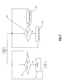
- fig. 5 is a block diagram of a first embodiment of the method of the invention;
- fig. 6 is a block diagram of a second embodiment of the method of the invention;
- fig. 7 is a block diagram of a third embodiment of the method of the invention;
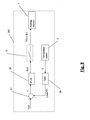
- fig. 8 represents a regulation block of fig. 7 in greater detail; and
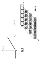
- figs. 9 and 10 show two preferred embodiments of power supply signals of a heater of the invention.
- The block diagram of a first embodiment of the system of the invention is shown in fig. 1.
- In this embodiment three functional blocks are identified, namely a
battery charger 1, a rechargeablepower supply device 2, and a bicycleelectronic device 3, which in the most general embodiment of the system of the invention is a device external to the system itself. - The bicycle
electronic device 3 and the rechargeablepower supply device 2 can indeed be housed in separate casings, indicated hereafter with thesame reference numerals electronic device 3 and thepower supply device 2 can be housed inside asame casing 2a. - The
battery charger 1 and thepower supply device 2 can be housed in separate casings as well, indicated hereafter with thesame reference numerals battery charger 1 and thepower supply device 2 can be housed inside asame casing 13. - Still alternatively, the
battery charger 1, thepower supply device 2 and the bicycleelectronic device 3 can be housed inside asame casing 14. - The
battery charger 1 is power supplied, in a per se known way, through connection to an external energy source P, like for example the mains, for example at 220V or 110V, or a cigarette lighter of an automobile. Thebattery charger 1 supplies power to thepower supply device 2 through aline 18 and thepower supply device 2 supplies power to the bicycleelectronic device 3 through aline 22. It should also be understood that in addition to the connections shown there is also a ground connection, not shown for the sake of simplicity. - In figure 1, the
electrical power connections battery charger 1, thepower supply device 2 and the bicycleelectronic device 3 are illustrated as removable, made through two pairs of multipolar connectors CN1, CN2. It is understood that one or both pairs of connectors CN1, CN2 will be missing in case only one or two casings are provided. - The rechargeable
power supply device 2 comprises apower supply unit 4, aheating element 5, and atemperature sensor 6. In the practical embodiment, thepower supply unit 4 could consist of many battery elements, for example series connected, to obtain an adequate voltage for the power supply of the bicycleelectronic device 3. Thepower supply unit 4 is of the rechargeable type, for example of the lithium-ion type with polymeric electrolyte. - The
heating element 5 preferably consists of a resistive sheet placed in contact with the outer surface of thepower supply unit 4. Thetemperature sensor 6 is arranged near to thepower supply unit 4, also preferably in contact with the outer surface of thepower supply unit 4, and it preferably consists of a passive element like an NTC (Negative Temperature Coefficient) thermistor. In different embodiments such a sensor could be of a different type, for example a PTC thermistor, an active (analogue or digital) sensor, etc. - Alternatively, the
heating element 5 and/or thetemperature sensor 6 can be part of thebattery charger 1 and come into thermal contact with thepower supply unit 4 when connected to thebattery charger 1, namely during charging. - The
battery charger 1 comprises a first, charging control, logic unit orcharge controller 7, of the known type, and a second, heating control, logic unit orheating controller 8. The first and thesecond logic units - The first, charging control,
logic unit 7 comprises aninput 19 connected to thetemperature sensor 6 of thepower supply device 2, and is connected to acharge circuit 9, for example of the linear or switching type, of thebattery charger 1. If thepower supply unit 4 consists of many battery elements, it can be provided to use asmany charge circuits 9 suitably connectable to the battery elements, for example as described in the citeddocument EP 1 557 926 A1 . - The second, heating control,
logic unit 8 comprises an input connected through adata line 20 to thetemperature sensor 6 of thepower supply device 2, and a drivingoutput 12 for aregulator 11 of the power of theheating element 5. Thepower regulator 11 can also be a simple ON/OFF switch. - The
power regulator 11 preferably consists of a MOSFET, but in different embodiments such a power regulator could, for example, consist of a transistor or even a relay. - In other embodiments, moreover, it can be provided to use two dedicated temperature sensors, one for the first, charging control,
logic unit 7 and one for the second, heating control,logic unit 8. - The first and the
second logic units charge circuit 9 are power supplied by the external energy source P through thepower supply line 21 through the interposition of power supply/regulator circuits 23 of a know type. - The
power regulator 11 is connected on one side to thepower supply line 21 and on the other side to theheating element 5 through theline 25. - The
battery charger 1 can advantageously be provided with one ormore interface devices 10, for example an input keyboard or keypad and a display. - The operation of the system of figure 1 shall be described hereafter with reference to figures 5-8.
- A second embodiment of the system according to the invention is illustrated in fig. 2.
- The embodiment of fig. 2 differs from the embodiment of fig. 1 in that the
power regulator 11 is associated with theheating element 5 inside thepower supply device 2. In this case, therefore, thecontrol output 12 of thepower regulator 11 comes out from thebattery charger 1 and reaches thepower supply device 2, through the pair of multipolar connectors CN1 when provided for. - Such an embodiment can be particularly advantageous when the
power regulator 11 is of the solid state type, for example of the MOSFET type, since during its actuation and deactuation, it undergoes heating caused by switching losses. The heat energy produced by such losses is advantageously exploited to heat the battery 4 (in addition to the heating produced by theheating element 6, as better described hereafter). - A third embodiment of the system according to the invention is illustrated in fig. 3.
- The embodiment of fig. 3 differs from the embodiment of fig. 1 in that the second
heating control unit 8 and thepower regulator 11 are housed in the casing of theelectronic device 3. In this case thepower supply line 21 comes out from thebattery charger 1 towards theelectronic device 3, through the pairs of multipolar connectors CN1 and CN2 when provided for, to power supply the second, heating control,logic unit 8. Thepower supply line 25 of theheater 5 and thedata line 20 between thetemperature sensor 6 and thetemperature controller 8 cross the pair of multipolar connectors CN2, when provided for. - In such an embodiment, moreover, the second
heating control unit 8 can consist of an electronic circuit mounted on the same printed circuit where the electronic circuits of theelectronic device 3 are arranged. - Alternatively, the
heating control unit 8 can belong to a microprocessor of theelectronic device 3, intended for other bicycle control functions, for example the management of an automatic or semiautomatic gearshift. - A fourth embodiment of the system according to the invention is illustrated in fig. 4.
- The embodiment of fig. 4 differs from the embodiment of fig. 3 in that the
power regulator 11 is associated with theheating element 5 inside the casing of thepower supply device 2. Thecontrol line 12 of theregulator 11 comes out from theelectronic device 3 towards thepower supply device 2 through the pair of multipolar connectors CN2, when provided for. - A first embodiment of the method according to the invention shall be described with reference to figure 5 and to the system of one of the embodiments described above.
- According to such a first embodiment of the method according to the invention different parameters are used, possibly settable by the user through the
interface devices 10 or through an interface device of theelectronic device 3 or computer cycle. - Such parameters comprise:
- T1 = lower limit charging temperature, typically a value set based upon the value provided by the manufacturer for the type of battery
power supply unit 4 used; for example T1=0°C for lithium-ion batteries with polymeric electrolyte; - T2 = upper limit charging temperature, typically a value set based upon the value provided by the manufacturer for the type of battery
power supply unit 4 used; for example T2=40°C for lithium-ion batteries with polymeric electrolyte; - Tlow = lower temperature threshold, a value selected upon experimental basis and based upon the type of battery
power supply unit 4 used; this lower temperature threshold is the temperature at which or above which one wishes to take or keep the temperature of thepower supply unit 4, and preferably it is selected a few degrees higher than the value of the lower limit charging temperature T1; for example Tlow=5°C for lithium-ion batteries with polymeric electrolyte. - The parameter Tlow can be omitted when the value of the lower limit charging temperature T1 is used instead.
- The range of temperatures between T1 and T2 is indicated, in the present description and in the attached claims, as closed charging temperature range.
- The values of T1 and T2 are stored in the first, charging control,
logic unit 7 whereas the value of Tlow is stored in the second, heating control,logic unit 8. - When the charging of the
power supply unit 4 needs to be carried out, thebattery charger 1 is connected to the external energy source P and, if necessary, to thepower supply device 2 through the pair of connectors CN1. - The first, charging control,
logic unit 7 detects inblock 90 the temperature value T of thepower supply unit 4 through thesensor 6. If the detected value T falls within the closed charging temperature range, i.e. T1<=T<=T2, the first, charging control,logic unit 7, inblock 91, enables thecharge circuit 9 to carry out the charging of thepower supply unit 4. If the detected value T falls outside the closed charging temperature range, i.e. T<T1 or T>T2, the first, charging control,logic unit 7 remains in inactive state and does not enable thecharge circuit 9 or else disables thecharge circuit 9 in case it had previously been enabled. The way of charging by thecharge circuit 9 can be of any type, for example as described in theaforementioned document EP 1 557 926 A1 , wherein charging provides for a first charging step at constant current and a second charging step at constant voltage. - Parallely to the described operation of the first, charging control,
logic unit 7, the second, heating control,logic unit 8 operates to carry out the "thermoregulation" of thepower supply unit 4 independently of the operation of the first, charging control,logic unit 7. - In
block 101, the heatingcontrol logic unit 8 detects the temperature value T of thepower supply unit 4 through thetemperature sensor 6. If the detected value T is lower than or equal to the lower limit temperature value Tlow, i.e. T <= Tlow, the heatingcontrol logic unit 8 inblock 102, through thecontrol output 12, actuates theheating element 5 driving thepower regulator 11, of the ON/OFF switch type, close. If, on the other hand, the detected value T is higher than the lower limit temperature value Tlow, i.e. T>Tlow, one proceeds to block 103 where the heatingcontrol logic unit 8, again through thecontrol output 12, deactuates theheating element 5 driving the power regulator or ON/OFF switch 11 open. - The regulation cycle thus implemented is therefore a temperature control performed on a threshold Tlow.
- The values of T1, T2 and Tlow are suitably selected to allow the correct operation of the apparatus. In particular, it has to be T1<=Tlow. In the case of use of a lithium-ion battery with polymeric electrolyte, the value of Tlow is advantageously selected a few degrees higher than the lower limit charging temperature T1, for example Tlow= 5°C. In this way the lower temperature threshold Tlow on which the temperature control is carried out is at a safety value that ensures the charging step by the first, charging control,
logic unit 7 taking possible inaccuracies in temperature detection by thesensor 6 into account, or of different readings, for whatever reason, by the twologic units - If in the initial charging step the temperature T of the
power supply unit 4 is lower than the lower limit temperature T1, theheating 102 consists of a preliminary operation with respect to the charging operation, which shall begin when the temperature of thepower supply unit 4 reaches the value T1. - On the other hand, if in the initial charging step the temperature T of the
power supply unit 4 is comprised between T1 and Tlow, obviously in case wherein T1>Tlow - for example T=3°C in the case described above with T1=0°C and Tlow=5°C - the heating and charging steps shall begin simultaneously. - In a second embodiment of the method according to the invention, in addition to the parameters T1, T2 and Tlow mentioned above a fourth parameter is used:
- Thigh = upper temperature threshold, a value selected on an experimental basis and based upon the type of battery
power supply unit 4 used, as well as the power of theheater 5; this upper temperature threshold is the temperature at which or above which one wishes to interrupt the heating of thepower supply unit 4; preferably, the upper temperature threshold is selected higher by a few degrees, more preferably by about 15°C, than the lower temperature threshold and lower, more preferably lower by about 25° C, than the upper limit of said closed charging temperature range; for example Thigh=15°C for lithium-ion batteries with polymeric electrolyte. - The value of Thigh is stored in the second, heating control,
logic unit 8. - With reference to fig. 6, parallely to the charging blocks 90, 91 described above, in
block 201 the heatingcontrol logic unit 8 detects the temperature value T of thepower supply unit 4 through thetemperature sensor 6. If the detected value T is lower than or equal to the lower limit temperature value Tlow, i.e. T <= Tlow, in ablock 202 the heatingcontrol logic unit 8, through the drivingoutput 12, actuates theheating element 5 closing thepower regulator 11, again of the ON/OFF switch type. If, on the other hand, the detected value T is higher than the lower limit temperature value Tlow, i.e. T>Tlow, one proceeds to block 203 where the detected temperature value T is compared with the upper temperature threshold Thigh. If the detected value T is higher than the upper temperature threshold Thigh, i.e. T > Thigh, inblock 204 the heatingcontrol logic unit 8 deactuates theheating element 5 opening thepower regulator 11 or ON/OFF switch. The regulation cycle thus implemented is therefore a temperature control performed on two thresholds Thigh and Tlow. - The temperature control performed on two thresholds Thigh and Tlow can be preferable with respect to the control with a single threshold Tlow since it allows the number of actuations and deactuations of the
power regulator 11 to be reduced with a reduction of the switching losses, especially when such a power regulator is a solid state power regulator (e.g. MOSFET). Moreover, this control performed on two thresholds Thigh and Tlow allows possible instability of the system to be avoided should the temperature T of thepower supply unit 4 quickly change about the temperature Tlow, which would involve continuous switching of thepower regulator 11 in case of control carried out on the lower temperature threshold Tlow only according to figure 5. - In a third embodiment of the method according to the invention the parameters T1 and T2 mentioned above, limits of the charging temperature range, and the lower temperature threshold, indicated here with Tref, are used.
- With reference to figure 7, parallely to the charging blocks 90, 91 described above, in
block 301 theheating control unit 8 detects the temperature value T of thepower supply unit 4 through thetemperature sensor 6. If the detected value T is higher than the lower temperature threshold or reference temperature Tref, theheating control unit 8 remains in inactive state, i.e. theheating element 5 is deactuated -block 302. If the detected value T is lower than or equal to the reference temperature Tref, theheating control unit 8 inblock 303, through the control output and theregulator 11, actuates theheating element 5 through a signal obtained with a closed loop feedback control system shown schematically in fig. 8, per se known. - The driving signal for the
heating element 5 is obtained as processing of an error signal suitably filtered by a P.I.D. regulator block, per se known. - More specifically, the temperature value T detected by the
temperature sensor 6 of thepower supply unit 4 is multiplied in amultiplier 26 by a gain value GAIN, which can also be unitary. The signal at the output of the multiplier, GAIN*T, is subtracted from the value Tref in asubtractor node 27. The output of thesubtractor node 27 is indicated as error signal ε = Tref-GAIN*T. - The error signal ε is sent to a P.I.D.
type regulator block 28, which has a transfer function of the proportional P, derivative D and/or integrative I type. - The output signal S(ε) of the
regulator block 28 is used to drive thepower regulator 11 so that the voltage V(t) at the ends of theheating element 5 or the current I(t) that flowing in theheating element 5 has the desired progression to provide the desired heat power. - For example, the drive signal S(ε) can be a signal that causes a voltage value V(t) at the ends of the
heating element 5, when of the resistive type, which increases as the error signal ε increases, as illustrated in the diagram of figure 9. - As a further example, the drive signal S(ε) can be a signal that causes a voltage value V(t) at the ends of the
heating element 5, or a current value I(t) through theheating element 5, when of the resistive type, pulse width modulated (PWM signal), wherein the duty cycle of the modulated signal increases as the error signal ε increases, as illustrated in fig. 10. - In the various embodiments described above, in case the
power supply unit 4 comprises many batteries, a plurality oftemperature sensors 6 can be provided for, to detect the respective temperatures. The various embodiments of the method of the invention described above can in this case be implemented with respect to the individual temperatures should a plurality ofheating elements 5 also be provided, or else with respect to the average temperature or to the minimum temperature among those of the various batteries making up thepower supply unit 4. - Those skilled in the art shall understand that several changes, additions, eliminations and replacements can be made to the embodiments described above without departing from the scope of protection of the invention defined by the attached claims.
Claims (56)
- Method for controlling the charging of a rechargeable battery power supply unit (4) for a bicycle electronic device (3), comprising the step of- detecting (6) at least one temperature (T) of the power supply unit (4), andcharacterised by the step of- supplying (102, 202, 303) heat energy (5) to the power supply unit (4) when the detected temperature (T) is lower than or equal to a lower temperature threshold (Tlow, Tref) within a closed charging temperature range (T1-T2) characteristic of said power supply unit (4).
- Method according to claim 1, further comprising the steps of providing an external energy source (P) and supplying electrical energy (91) to the power supply unit.
- Method according to claim 2, characterised in that the step of supplying electrical energy (91) only occurs when the detected temperature (T) is comprised within said closed charging temperature range (T1-T2).
- Method according to any of the previous claims, further comprising the step of providing an external energy source (P) and supplying said heat energy to the power supply unit (4) from said external source (P).
- Method according to any of the previous claims, characterised in that the lower temperature threshold (Tlow) is higher than the lower limit (T1) of said closed charging temperature range (T1-T2).
- Method according to claim 5, characterised in that the lower temperature threshold (Tlow) is higher by about 5° C than the lower limit (T1) of said closed charging temperature range (T1-T2).
- Method according to any of the previous claims, characterised in that said step of supplying heat energy (202) to the power supply unit (4) is carried out until the detected temperature (T) becomes higher (203) than an upper temperature threshold (Thigh).
- Method according to claim 7, characterised in that the upper temperature threshold (Thigh) is lower than the upper limit (T2) of said closed charging temperature range (T1-T2).
- Method according to claim 8, characterised in that the upper temperature threshold (Thigh) is about 25° C lower than the upper limit (T2) of said closed charging temperature range (T1-T2).
- Method according to any of claims 7-9, characterised in that the upper temperature threshold (Thigh) is about 15° C higher than the lower limit (T1) of said closed charging temperature range (T1-T2).
- Method according to any of the previous claims, characterised in that said step of supplying heat energy (303) comprises providing heat power as a function of a difference (ε) between the lower temperature threshold (Tref) and a temperature proportional to the detected temperature (T).
- Method according to any of the previous claims, characterised in that said step of supplying heat energy (102, 202, 303) is carried out by voltage- or current- supplying power to a heating element (5) of the resistive type thermally coupled with the power supply unit (4).
- Method according to any of claims 2-12, characterised in that said step of detecting (6) at least one temperature (T) of the power supply unit (4) comprises detecting a first temperature for controlling the execution of said step of supplying electrical energy (91) and a second temperature for controlling the execution of said step of supplying heat energy (102, 202, 303).
- Method according to any of the previous claims, characterised in that at least one of the steps of detecting (6) a temperature (T), supplying heat energy (102, 202, 303) and supplying electrical energy (91) is carried out independently for each of a plurality of batteries of said rechargeable battery power supply unit (4).
- Power supply system for a bicycle electronic device (3), comprising- a rechargeable battery power supply unit (4),- at least one sensor (6) of a temperature (T) of the power supply unit (2, 2a),characterised in that it further comprises- at least one selectively activatable (8, 11) heating element (5), that can be thermally associated with the power supply unit (4), and- a heating controller (8) that receives in input the output of said at least one temperature sensor (6) and actuates said heating element (5) when the detected temperature (T) is lower than or equal to a lower temperature threshold (Tlow, Tref) within a closed charging temperature range (T1-T2) characteristic of said power supply unit (4).
- System according to claim 15, further comprising an electrical circuit (9, 23) for receiving energy from an external energy source (P) and for selectively supplying (7) charging energy to the power supply unit (4) .
- System according to any of claims 15-16, characterised in that said power supply unit (4) comprises at least two batteries, and at least one heating element (5) is thermally associated with each battery.
- System according to any of claims 15-17, characterised in that said power supply unit (4) comprises at least two batteries, and at least one temperature sensor (6) is thermally associated with each battery.
- System according to any of claims 15-18, characterised by comprising a power regulator (11) connected between a power supply line (21) of the system and said heating element (5), and driven by said heating controller (8) to selectively actuate said at least one heating element (5).
- System according to claim 19, characterised in that said power regulator (11) is selected from the group consisting of relays and solid-state element devices.
- System according to any of claims 15-20, characterised in that said heating controller (8) comprises a multiplier (26) of the output signal (T) of said at least one temperature sensor (6), a subtractor (27) for subtracting the output of the multiplier (GAIN*T) from the lower temperature threshold (Tref) and for obtaining an error signal (ε), and a P.I.D. type regulator block (28) acting upon said error signal (ε) to output a driving signal (S(ε)) for said power regulator (11), the driving of said power regulator (11) regulating a voltage at the ends of or a current through said heating element (5).
- System according to claim 21, characterised in that said at least one heating element (5) is of the resistive type and said P.I.D. regulator block (28) causes a voltage value at the ends of or a current through said heating element (5) that increases as the error signal (ε) increases.
- System according to claim 21, characterised in that said at least one heating element (5) is of the resistive type and said P.I.D. regulator block (28) causes a modulated voltage (V(t)) at the ends of said heating element (5), or a modulated current (I(t)) through said heating element (5), the duty cycle of which increases as the error signal (ε) increases.
- System according to any of claims 15-23, characterised in that said heating element (5) comprises at least one resistive sheet applied to at least one battery of said power supply unit (4).
- System according to any of claims 15-24, characterised in that said at least one temperature sensor (6) comprises a thermistor.
- System according to any of claims 16-25, characterised by further comprising a charge controller (7) that receives in input an output of said at least one temperature sensor (6) and controls said electrical circuit (9) to actuate the supply of electrical charging energy only when the detected temperature (T) is within said closed charging temperature range (T1-T2).
- System according to claim 26, characterised in that said at least one temperature sensor (6) comprises at least one first temperature sensor connected to the charge controller (7) and at least one second temperature sensor connected to the heating controller (8) .
- System according to any of claims 16-27, characterised in that said electrical circuit (9, 23) comprises at least one charge circuit (9) of the linear or switching type.
- System according to claim 28, characterised in that said charge circuit (9) is controlled by the charge controller (7) for carrying out a first temporal charging step at constant current and a second temporal charging step at constant voltage.
- System according to any of claims 26-29, characterised in that said charge controller (7) and said heating controller (8) are embodied in a common microprocessor.
- System according to any of claims 16-30, further comprising a power supply and regulator circuit (23) that can be connected to said external energy source (P) to provide a regulated power supply (21) to said system.
- System according to any of claims 15-31, further comprising at least one user interface device (10).
- System according to any of claims 15-32, further comprising at least one electronic device (3) for controlling an electronic gearshift and/or for acquiring, displaying and controlling bicycle riding parameters and other functions.
- System according to any of claims 15-33, characterised in that its components are housed in a single casing (14), fixed to the bicycle frame.
- System according to any of claims 16-33, characterised in that the electrical charging circuit (9, 23) is housed in a first casing (1) and the power supply unit (4) is housed in a second casing (2, 2a), the first casing (1) and the second casing (2, 2a) being mechanically and electrically removably connectable.
- System according to claims 26 and 35, characterised in that the charge controller (7) is housed in the first casing (1).
- System according to claims 32 and 35, characterised in that said at least one interface device (10) is housed in the first casing (1).
- System according to any of claims 35-37, characterised in that said at least one temperature sensor (6) is housed in the second casing (2, 2a).
- System according to any of claims 35-38, characterised in that said at least one heating element (5) is housed in said second casing (2, 2a).
- System according to any of claims 35-39, characterised in that said heating controller (8) is housed in the first casing (1).
- System according to any of claims 35-39, characterised in that said heating controller (8) is housed in the second casing (1).
- System according to claims 33 and 35, characterised in that said at least one electronic device (3) is housed in the second casing (2a).
- System according to claims 41 and 42, characterised in that the heating controller (8) comprises an electronic circuit mounted on a printed circuit of the electronic device (3).
- System according to claims 41 and 42, characterised in that the heating controller (8) is embodied in a microprocessor of the electronic device (3).
- System according to claims 19 and 35, characterised in that said power regulator (11) is housed in the first casing (1).
- System according to claims 19 and 35, characterised in that said power regulator (11) is housed in the second casing (2, 2a).
- System according to any of claims 35-46, characterised in that said at least one electronic device (3) is housed in a third casing (3), the second casing (2, 2a) being mechanically and electrically connectable to the third casing (3).
- System according to claim 47, characterised in that said heating controller (8) is housed in the third casing (3).
- System according to claim 48, characterised in that the heating controller (8) comprises an electronic circuit mounted on a printed circuit of the electronic device (3).
- System according to claim 49, characterised in that the heating controller (8) is embodied in a microprocessor of the electronic device (3).
- System according to any of claims 47-50, characterised in that said power regulator (11) is housed in the third casing (3).
- Power supply device (2, 2a) for a bicycle electronic device comprising- a power supply unit (4) comprising at least one rechargeable battery,- a connector (CN1) for a removable electrical power and data connection with a battery charger,- at least one temperature sensor (6) thermally coupled with said power supply unit (4),- at least one selectively activatable heating element (5), thermally coupled with said power supply unit (4),wherein said heating element (5) is selectively actuated when said power supply device (2, 2a) is connected to said battery charger (1) and when the temperature (T) detected by said sensor is lower than or equal to a lower temperature threshold (Tlow, Tref) within a closed charging temperature range, characteristic of said power supply unit (4).
- Power supply device (2, 2a) according to claim 52, further comprising a power regulator (11) for the selective actuation of said heating element (5), said power regulator (11) being controlled by said battery charger (1).
- Power supply device (2, 2a) according to claim 52, further comprising a connector (CN2) for a removable electrical power and data connection with an electronic device (3) for controlling an electronic gearshift and/or for acquiring, displaying and controlling bicycle riding parameters and other functions, and a power regulator (11) for the selective actuation of said heating element (5), said power regulator (11) being controlled by said electronic device (3).
- Battery charger (1) for a bicycle electronic device (3), comprising- a connector (CN1) for a removable electrical power and data connection with a power supply unit (4) of said electronic device (3),- an electrical circuit (9, 23) for receiving energy from an external energy source (P) and for selectively supplying (7) charging energy to the power supply unit (4),- a heating controller (8) that receives in input a signal (6) indicative of a detected temperature (T) of said power supply unit (4) and provides a signal for actuating a heating element (5) of said power supply unit (4) when the detected temperature (T) is lower than or equal to a lower temperature threshold (Tlow, Tref) within a closed charging temperature range characteristic of said power supply unit (4).
- Bicycle electronic device, comprising- a connector (CN2) for a removable electrical power and data connection with a power supply unit (4),- a heating controller (8) that receives in input a signal (6) indicative of a detected temperature (T) of said power supply unit (4) and provides a signal for actuating a heating element (5) of said power supply unit (4) when the detected temperature (T) is lower than or equal to a lower temperature threshold (Tlow, Tref) within a closed charging temperature range characteristic of said power supply unit (4).
Applications Claiming Priority (1)
| Application Number | Priority Date | Filing Date | Title |
|---|---|---|---|
| IT001296A ITMI20061296A1 (en) | 2006-07-04 | 2006-07-04 | METHOD OF CONTROL AND SYSTEM OF CHARGING A BATTERY POWER UNIT |
Publications (2)
| Publication Number | Publication Date |
|---|---|
| EP1876510A2 true EP1876510A2 (en) | 2008-01-09 |
| EP1876510A3 EP1876510A3 (en) | 2011-07-27 |
Family
ID=37499558
Family Applications (1)
| Application Number | Title | Priority Date | Filing Date |
|---|---|---|---|
| EP07012164A Withdrawn EP1876510A3 (en) | 2006-07-04 | 2007-06-21 | Method for controlling and system for charging a battery power supply unit |
Country Status (6)
| Country | Link |
|---|---|
| US (2) | US20080042621A1 (en) |
| EP (1) | EP1876510A3 (en) |
| JP (1) | JP2008061490A (en) |
| CN (1) | CN101102054B (en) |
| IT (1) | ITMI20061296A1 (en) |
| TW (1) | TWI441370B (en) |
Cited By (5)
| Publication number | Priority date | Publication date | Assignee | Title |
|---|---|---|---|---|
| CN102738840A (en) * | 2011-04-12 | 2012-10-17 | 河南科隆集团有限公司 | Low temperature charging device of lithium ion battery |
| EP2149958A3 (en) * | 2008-07-11 | 2014-01-22 | Sony Corporation | Battery pack, information processing apparatus, charge control system, charge control method by battery pack, and charge control method by charge control system |
| WO2013170980A3 (en) * | 2012-05-14 | 2014-02-27 | Robert Bosch Gmbh | Charging system for motor vehicles |
| FR2997232A1 (en) * | 2012-10-23 | 2014-04-25 | Renault Sa | Method for recharging lithium-ion battery of e.g. electric car, involves utilizing discharge current output from traction battery to heat traction battery, and providing charging current from distribution network to charge electric battery |
| EP3188341A4 (en) * | 2014-09-01 | 2018-07-25 | Guangdong Oppo Mobile Telecommunications Corp., Ltd. | Terminal |
Families Citing this family (40)
| Publication number | Priority date | Publication date | Assignee | Title |
|---|---|---|---|---|
| ITMI20061296A1 (en) | 2006-07-04 | 2008-01-05 | Campagnolo Srl | METHOD OF CONTROL AND SYSTEM OF CHARGING A BATTERY POWER UNIT |
| ITMI20061295A1 (en) * | 2006-07-04 | 2008-01-05 | Campagnolo Srl | MEDOTO AND ELECTRICAL ENERGY DELIVERY SYSTEM FROM A BATTERY POWER UNIT |
| US8134462B1 (en) * | 2008-08-08 | 2012-03-13 | The United States Of America As Represented By The Secretary Of The Navy | Self-contained sensor package for water security and safety |
| JP5363143B2 (en) * | 2009-03-02 | 2013-12-11 | オリンパス株式会社 | Data communication system and receiving apparatus |
| CN202997003U (en) * | 2009-12-04 | 2013-06-12 | 三洋电机株式会社 | Power storage unit, power generation system and charging and discharging system |
| US9431688B2 (en) * | 2010-05-21 | 2016-08-30 | GM Global Technology Operations LLC | Method for heating a high voltage vehicle battery |
| CN102244306B (en) * | 2010-07-30 | 2013-12-11 | 惠州Tcl移动通信有限公司 | Method for charging mobile phone under low temperature |
| US8957543B2 (en) * | 2010-10-15 | 2015-02-17 | Nextek Power Systems, Inc. | Arrangement for and method of dynamically managing electrical power between an electrical power source and an electrical load |
| CN102139646B (en) * | 2011-02-18 | 2012-11-28 | 奇瑞汽车股份有限公司 | Power battery thermal management system and control method thereof |
| JP5736859B2 (en) * | 2011-03-11 | 2015-06-17 | 日産自動車株式会社 | Battery pack heater module connection structure |
| US8890467B2 (en) * | 2011-03-28 | 2014-11-18 | Continental Automotive Systems, Inc. | System for controlling battery conditions |
| CN102694404B (en) * | 2012-06-07 | 2014-10-22 | 中国科学技术大学 | Control method, control module and control system for power lithium battery pack |
| WO2014003085A1 (en) | 2012-06-27 | 2014-01-03 | Semiconductor Energy Laboratory Co., Ltd. | Power storage unit and solar power generation unit |
| CN102842935A (en) * | 2012-09-20 | 2012-12-26 | 上海广为美线电源电器有限公司 | Lithium battery emergency starting power supply with low temperature automatic pre-heating function |
| CN104124482B (en) * | 2013-04-28 | 2017-10-10 | 华为终端有限公司 | A kind of charging method, device and electronic equipment |
| TWI644194B (en) * | 2013-08-06 | 2018-12-11 | 睿能創意公司 | Electrical energy storage device thermal profile adjustment controller, method and electric vehicle system thereof |
| ITMI20131902A1 (en) * | 2013-11-15 | 2015-05-16 | Campagnolo Srl | ELECTRONIC BICYCLE SYSTEM |
| CN106104959B (en) * | 2014-03-14 | 2019-04-12 | 吉瑞高新科技股份有限公司 | Electronic cigarette charger |
| CN106532186B (en) * | 2014-09-01 | 2019-10-22 | Oppo广东移动通信有限公司 | A charging method, charging circuit and mobile terminal |
| CA2963392A1 (en) | 2014-10-03 | 2016-04-07 | Elitise Llc | Battery module architecture with horizontal and vertical expandability |
| DE102015102345A1 (en) | 2015-02-19 | 2016-08-25 | Dr. Ing. H.C. F. Porsche Aktiengesellschaft | Method for charging a rechargeable battery |
| US10377251B2 (en) * | 2015-03-26 | 2019-08-13 | Proterra Inc. | Electric vehicle charging interface |
| US20170054187A1 (en) * | 2015-08-18 | 2017-02-23 | Emerson Network Power, Energy Systems, North America, Inc. | Battery heater controllers and infrastructure cabinets including battery heater controllers |
| CN106207295A (en) * | 2016-08-19 | 2016-12-07 | 北汽福田汽车股份有限公司 | Charging method, battery system and vehicle for battery system |
| JP6775117B2 (en) * | 2016-10-26 | 2020-10-28 | パナソニックIpマネジメント株式会社 | Power storage device |
| CN106787043B (en) * | 2016-12-21 | 2019-02-01 | 北京新能源汽车股份有限公司 | Control method and device for temperature protection device, charging gun, and vehicle-mounted charger |
| EP3566259B1 (en) * | 2017-01-09 | 2023-03-08 | Milwaukee Electric Tool Corporation | Battery pack |
| US10263443B2 (en) * | 2017-01-13 | 2019-04-16 | Hand Held Products, Inc. | Power capacity indicator |
| CN207265713U (en) * | 2017-07-28 | 2018-04-20 | 特斯拉公司 | Charging system with thermal protection |
| US11493967B2 (en) * | 2018-06-01 | 2022-11-08 | Interdigital Madison Patent Holdings, Sas | Thermal shutdown with hysteresis |
| CN110077281B (en) * | 2019-04-30 | 2020-12-15 | 浙江吉利控股集团有限公司 | A method and system for charging and heating a power battery of a plug-in hybrid electric vehicle |
| CN112440790B (en) * | 2019-09-05 | 2024-11-08 | 国创移动能源创新中心(江苏)有限公司 | Charging pile and heating, heat dissipation and heat recovery device and method thereof |
| KR102851396B1 (en) | 2019-10-10 | 2025-08-26 | 주식회사 엘지에너지솔루션 | Apparatus for controlling heating pad |
| CN111682618B (en) * | 2020-06-23 | 2022-04-29 | 维沃移动通信有限公司 | Electronic equipment, charging method and device |
| KR102726227B1 (en) * | 2021-01-28 | 2024-11-05 | 컨템포러리 엠퍼렉스 테크놀로지 (홍콩) 리미티드 | Charging method, battery management system of power battery and charging file |
| KR102644606B1 (en) * | 2021-01-28 | 2024-03-08 | 컨템포러리 엠퍼렉스 테크놀로지 씨오., 리미티드 | Charging method and power conversion device |
| KR102893180B1 (en) * | 2021-01-28 | 2025-12-01 | 컨템포러리 엠퍼렉스 테크놀로지 (홍콩) 리미티드 | Charging method, battery management system of power battery and charging file |
| WO2022261910A1 (en) * | 2021-06-17 | 2022-12-22 | 宁德时代新能源科技股份有限公司 | Charging control method and apparatus, battery management system, and readable storage medium |
| KR102675297B1 (en) * | 2021-12-24 | 2024-06-13 | 에스케이씨 주식회사 | Moviing apparatus capable of wireless charging, wireless cahrging apparatus and method for controlling wireless charging system |
| CN115589048B (en) * | 2022-11-07 | 2025-07-11 | 深圳慧能泰半导体科技有限公司 | A protection system, charging cable and charging device |
Citations (1)
| Publication number | Priority date | Publication date | Assignee | Title |
|---|---|---|---|---|
| DE4017475A1 (en) * | 1990-05-31 | 1991-12-05 | Standard Elektrik Lorenz Ag | ARRANGEMENT WITH AN ELECTRIC BATTERY |
Family Cites Families (58)
| Publication number | Priority date | Publication date | Assignee | Title |
|---|---|---|---|---|
| US2516048A (en) * | 1946-02-27 | 1950-07-18 | Willard Storage Battery Co | Heated battery |
| US3895283A (en) | 1973-11-26 | 1975-07-15 | Vapor Corp | Temperature responsive battery charging circuit |
| DE3617439A1 (en) * | 1985-11-14 | 1987-11-26 | Messerschmitt Boelkow Blohm | Method and arrangement for defrosting a solar cell panel on a motor vehicle |
| US5339018A (en) * | 1989-06-30 | 1994-08-16 | Analog Devices, Inc. | Integrated circuit monitor for storage battery voltage and temperature |
| DE4142628C1 (en) * | 1991-12-21 | 1993-05-06 | Dieter Braun | |
| DE4216045A1 (en) | 1992-05-15 | 1993-11-18 | Bosch Gmbh Robert | Multiple charger |
| JP3567473B2 (en) * | 1993-09-24 | 2004-09-22 | カシオ計算機株式会社 | Charging device and traveling vehicle computer |
| TW259901B (en) | 1994-10-26 | 1995-10-11 | Ind Tech Res Inst | Charging method and device thereof |
| JP3414004B2 (en) * | 1994-11-22 | 2003-06-09 | 日産自動車株式会社 | Electric vehicle battery temperature controller |
| US5795664A (en) * | 1995-12-05 | 1998-08-18 | Norand Corporation | Rechargeable battery system having intelligent temperature control |
| TW314668B (en) | 1996-01-31 | 1997-09-01 | Tay-Her Yang | Engine-driven auxiliary battery charger system with automatic monitoring function |
| US6451041B1 (en) * | 1996-02-29 | 2002-09-17 | Stephen P. Moenning | Apparatus for protecting a port site opening in the wall of a body cavity and reducing electrosurgical injuries |
| US5710507A (en) * | 1996-04-26 | 1998-01-20 | Lucent Technologies Inc. | Temperature-controlled battery reserve system and method of operation thereof |
| JPH10201124A (en) * | 1997-01-09 | 1998-07-31 | Takashi Toyomura | Charging system of power storing means |
| JPH10284133A (en) * | 1997-04-08 | 1998-10-23 | Sony Corp | Battery pack and battery pack charging method |
| US5834131A (en) * | 1997-05-02 | 1998-11-10 | Itt Manufacturing Enterprises, Inc. | Self warming low cost tactical electronics battery |
| US6181103B1 (en) * | 1997-05-27 | 2001-01-30 | Shu-Chin Chen | Advanced intelligent computer power management system |
| JPH1155869A (en) * | 1997-07-29 | 1999-02-26 | Matsushita Electric Ind Co Ltd | Battery temperature automatic adjustment charger |
| JP3765913B2 (en) | 1997-09-15 | 2006-04-12 | 本田技研工業株式会社 | Battery rental equipment |
| CA2225585A1 (en) | 1997-12-12 | 1999-06-12 | Hydro-Quebec | Battery control system |
| US6002240A (en) * | 1997-12-12 | 1999-12-14 | Dell Usa, L.P. | Self heating of batteries at low temperatures |
| JP3563965B2 (en) * | 1998-06-29 | 2004-09-08 | 本田技研工業株式会社 | Battery charger |
| CN1205720C (en) * | 1998-10-15 | 2005-06-08 | 雅马哈发动机株式会社 | Power system for electric vehicle |
| CN1182986C (en) * | 1998-12-28 | 2005-01-05 | 雅马哈发动机株式会社 | Power supply system for electric vehicles |
| JP2000228230A (en) * | 1999-02-08 | 2000-08-15 | Nec Corp | Battery pack |
| JP2001021628A (en) * | 1999-07-02 | 2001-01-26 | Yazaki Corp | Battery capacity measurement device with chargeable capacity calculation function using temperature sensor |
| US6246600B1 (en) * | 2000-07-28 | 2001-06-12 | Motorola, Inc. | Multi-use battery |
| US6271648B1 (en) * | 2000-09-27 | 2001-08-07 | Ford Global Tech., Inc. | Method of preconditioning a battery to improve cold temperature starting of a vehicle |
| JP2002125326A (en) * | 2000-10-12 | 2002-04-26 | Honda Motor Co Ltd | Battery charge control method |
| JP3936179B2 (en) | 2001-11-30 | 2007-06-27 | パナソニック・イーブイ・エナジー株式会社 | Battery power supply device and current detection method thereof |
| JP4340020B2 (en) * | 2001-04-10 | 2009-10-07 | パナソニック株式会社 | Charge control method for secondary battery for automatic guided vehicle |
| US20050007406A1 (en) * | 2001-04-19 | 2005-01-13 | Haas William S. | Controllable thermal warming devices |
| JP3772765B2 (en) | 2001-05-11 | 2006-05-10 | トヨタ自動車株式会社 | Refresh charge control device |
| US6624611B2 (en) * | 2001-10-30 | 2003-09-23 | Taw Security Concepts, Inc. | Sensing vehicle battery charging and/or engine block heating to trigger pre-heating of a mobile electronic device |
| JP2003168491A (en) * | 2001-11-29 | 2003-06-13 | Fuji Photo Film Co Ltd | Secondary battery unit, temperature control equipment for secondary battery, charging equipment, charging program, and charging method |
| JP4020650B2 (en) | 2002-01-30 | 2007-12-12 | 三洋電機株式会社 | Battery device for vehicle |
| JP4030331B2 (en) * | 2002-03-28 | 2008-01-09 | 日本碍子株式会社 | Control device for sodium-sulfur battery |
| US7096727B2 (en) | 2002-05-10 | 2006-08-29 | Michelin Recherche Et Technique S.A. | System and method for generating electric power from a rotating tire's mechanical energy |
| US6725713B2 (en) * | 2002-05-10 | 2004-04-27 | Michelin & Recherche Et Technique S.A. | System for generating electric power from a rotating tire's mechanical energy using reinforced piezoelectric materials |
| US6861824B1 (en) * | 2002-07-10 | 2005-03-01 | Arquesttechnology, Inc. | Charger system with dual-level current regulation and dual-level thermal regulation |
| US7327122B2 (en) | 2002-07-17 | 2008-02-05 | Mathews Associates, Inc. | Battery heating circuit |
| US20060012342A1 (en) * | 2002-07-17 | 2006-01-19 | Mathews Associates, Inc. | Self-heating battery that automatically adjusts its heat setting |
| US6781510B2 (en) * | 2002-07-24 | 2004-08-24 | Shimano, Inc. | Bicycle computer control arrangement and method |
| EP1384659B1 (en) * | 2002-07-24 | 2009-12-23 | Shimano Inc. | Bicycle computer control arrangement and method |
| KR100471249B1 (en) * | 2002-08-23 | 2005-03-10 | 현대자동차주식회사 | Battery temperature management method of electric vehicle |
| JP2004362949A (en) * | 2003-06-05 | 2004-12-24 | Sony Corp | Battery device, battery heating method, and electric assist bicycle |
| JP4263052B2 (en) * | 2003-08-01 | 2009-05-13 | 日産ディーゼル工業株式会社 | Temperature control device for electric double layer capacitor |
| JP4072476B2 (en) * | 2003-08-01 | 2008-04-09 | 日産ディーゼル工業株式会社 | Power storage device |
| US20060028182A1 (en) * | 2004-07-23 | 2006-02-09 | Jihui Yang | Thermoelectric methods to control temperature of batteries |
| ATE538525T1 (en) | 2004-01-20 | 2012-01-15 | Campagnolo Srl | RECHARGEABLE POWER SUPPLY UNIT FOR A BICYCLE |
| JP4390609B2 (en) * | 2004-03-31 | 2009-12-24 | 三洋電機株式会社 | Power supply for vehicle |
| US7154068B2 (en) * | 2004-05-26 | 2006-12-26 | Ford Global Technologies, Llc | Method and system for a vehicle battery temperature control |
| JP2006127920A (en) | 2004-10-29 | 2006-05-18 | Sanyo Electric Co Ltd | Power supply device |
| JP4768273B2 (en) * | 2005-01-12 | 2011-09-07 | Necエナジーデバイス株式会社 | Battery pack |
| CN100372169C (en) | 2005-10-17 | 2008-02-27 | 李慧琪 | Thermal balance treating method and device for lithium ion power battery group |
| ITMI20061296A1 (en) | 2006-07-04 | 2008-01-05 | Campagnolo Srl | METHOD OF CONTROL AND SYSTEM OF CHARGING A BATTERY POWER UNIT |
| ITMI20061295A1 (en) * | 2006-07-04 | 2008-01-05 | Campagnolo Srl | MEDOTO AND ELECTRICAL ENERGY DELIVERY SYSTEM FROM A BATTERY POWER UNIT |
| US10279684B2 (en) * | 2008-12-08 | 2019-05-07 | Ford Global Technologies, Llc | System and method for controlling heating in a hybrid vehicle using a power source external to the hybrid vehicle |
-
2006
- 2006-07-04 IT IT001296A patent/ITMI20061296A1/en unknown
-
2007
- 2007-06-21 EP EP07012164A patent/EP1876510A3/en not_active Withdrawn
- 2007-06-26 JP JP2007167835A patent/JP2008061490A/en active Pending
- 2007-07-02 US US11/772,712 patent/US20080042621A1/en not_active Abandoned
- 2007-07-04 CN CN2007101271509A patent/CN101102054B/en not_active Expired - Fee Related
- 2007-07-04 TW TW096124365A patent/TWI441370B/en not_active IP Right Cessation
-
2015
- 2015-12-28 US US14/980,569 patent/US9469202B2/en not_active Expired - Fee Related
Patent Citations (1)
| Publication number | Priority date | Publication date | Assignee | Title |
|---|---|---|---|---|
| DE4017475A1 (en) * | 1990-05-31 | 1991-12-05 | Standard Elektrik Lorenz Ag | ARRANGEMENT WITH AN ELECTRIC BATTERY |
Cited By (7)
| Publication number | Priority date | Publication date | Assignee | Title |
|---|---|---|---|---|
| EP2149958A3 (en) * | 2008-07-11 | 2014-01-22 | Sony Corporation | Battery pack, information processing apparatus, charge control system, charge control method by battery pack, and charge control method by charge control system |
| CN102738840A (en) * | 2011-04-12 | 2012-10-17 | 河南科隆集团有限公司 | Low temperature charging device of lithium ion battery |
| WO2013170980A3 (en) * | 2012-05-14 | 2014-02-27 | Robert Bosch Gmbh | Charging system for motor vehicles |
| US9511673B2 (en) | 2012-05-14 | 2016-12-06 | Robert Bosch Gmbh | Heated connection for charging electric vehicles |
| FR2997232A1 (en) * | 2012-10-23 | 2014-04-25 | Renault Sa | Method for recharging lithium-ion battery of e.g. electric car, involves utilizing discharge current output from traction battery to heat traction battery, and providing charging current from distribution network to charge electric battery |
| EP3188341A4 (en) * | 2014-09-01 | 2018-07-25 | Guangdong Oppo Mobile Telecommunications Corp., Ltd. | Terminal |
| US10826309B2 (en) | 2014-09-01 | 2020-11-03 | Guangdong Oppo Mobile Telecommunications Corp., Ltd. | Terminal, heating apparatus and charging method for battery |
Also Published As
| Publication number | Publication date |
|---|---|
| CN101102054A (en) | 2008-01-09 |
| US20080042621A1 (en) | 2008-02-21 |
| US9469202B2 (en) | 2016-10-18 |
| EP1876510A3 (en) | 2011-07-27 |
| TWI441370B (en) | 2014-06-11 |
| CN101102054B (en) | 2012-09-05 |
| TW200824168A (en) | 2008-06-01 |
| ITMI20061296A1 (en) | 2008-01-05 |
| US20160185234A1 (en) | 2016-06-30 |
| JP2008061490A (en) | 2008-03-13 |
Similar Documents
| Publication | Publication Date | Title |
|---|---|---|
| EP1876510A2 (en) | Method for controlling and system for charging a battery power supply unit | |
| US9634518B2 (en) | Method and system for supplying electrical energy from a battery power supply unit to a heating element | |
| US12114401B2 (en) | Electrically heated jacket | |
| EP3855555B1 (en) | Battery pack | |
| EP2244349A1 (en) | Battery charger and method for charging a battery | |
| US20050218136A1 (en) | Car power source apparatus | |
| EP2058915A3 (en) | Mobile phone terminal and charging system | |
| JP2000040536A (en) | Battery warming device | |
| JP6577658B2 (en) | Drive device for electrically assisted vehicle, electrically assisted vehicle, and power storage device | |
| JP2001224140A (en) | Charging device | |
| WO2021215572A1 (en) | Heater system for heating battery for electric vehicle and battery for electric vehicle having same | |
| JP2008204867A (en) | Battery pack | |
| EP1517091B1 (en) | Electric cooking apparatus and method of controlling the same | |
| JP5486518B2 (en) | Battery pack | |
| JP2009213196A (en) | Device for adjusting capacity of battery pack | |
| CN106299547B (en) | Lithium-ions battery power supply automatic equalization heating system and heating method | |
| JP7742034B2 (en) | power supply | |
| US20260005325A1 (en) | Battery pack terminal temperature monitoring | |
| JP2006196256A (en) | Battery pack | |
| JP2008104349A (en) | Charger | |
| CN109907875A (en) | A kind of itch stopping apparatus and its method of multi-temperature zone gradient-controllable heating | |
| JP4936807B2 (en) | Image forming apparatus having power storage device | |
| JPH08113186A (en) | Lamp control device for motor-driven bicycle | |
| KR20060015902A (en) | Composite heater device and composite heater heating device using the same |
Legal Events
| Date | Code | Title | Description |
|---|---|---|---|
| PUAI | Public reference made under article 153(3) epc to a published international application that has entered the european phase |
Free format text: ORIGINAL CODE: 0009012 |
|
| AK | Designated contracting states |
Kind code of ref document: A2 Designated state(s): AT BE BG CH CY CZ DE DK EE ES FI FR GB GR HU IE IS IT LI LT LU LV MC MT NL PL PT RO SE SI SK TR |
|
| AX | Request for extension of the european patent |
Extension state: AL BA HR MK YU |
|
| PUAL | Search report despatched |
Free format text: ORIGINAL CODE: 0009013 |
|
| AK | Designated contracting states |
Kind code of ref document: A3 Designated state(s): AT BE BG CH CY CZ DE DK EE ES FI FR GB GR HU IE IS IT LI LT LU LV MC MT NL PL PT RO SE SI SK TR |
|
| AX | Request for extension of the european patent |
Extension state: AL BA HR MK RS |
|
| 17P | Request for examination filed |
Effective date: 20120127 |
|
| AKX | Designation fees paid |
Designated state(s): AT BE BG CH CY CZ DE DK EE ES FI FR GB GR HU IE IS IT LI LT LU LV MC MT NL PL PT RO SE SI SK TR |
|
| STAA | Information on the status of an ep patent application or granted ep patent |
Free format text: STATUS: EXAMINATION IS IN PROGRESS |
|
| 17Q | First examination report despatched |
Effective date: 20170719 |
|
| STAA | Information on the status of an ep patent application or granted ep patent |
Free format text: STATUS: THE APPLICATION IS DEEMED TO BE WITHDRAWN |
|
| 18D | Application deemed to be withdrawn |
Effective date: 20190815 |