EP1874629B1 - Device for packaging items, in particular confectionery - Google Patents
Device for packaging items, in particular confectionery Download PDFInfo
- Publication number
- EP1874629B1 EP1874629B1 EP06725550A EP06725550A EP1874629B1 EP 1874629 B1 EP1874629 B1 EP 1874629B1 EP 06725550 A EP06725550 A EP 06725550A EP 06725550 A EP06725550 A EP 06725550A EP 1874629 B1 EP1874629 B1 EP 1874629B1
- Authority
- EP
- European Patent Office
- Prior art keywords
- heating
- heat
- packaging
- heating body
- sheet
- Prior art date
- Legal status (The legal status is an assumption and is not a legal conclusion. Google has not performed a legal analysis and makes no representation as to the accuracy of the status listed.)
- Expired - Lifetime
Links
Images



Classifications
-
- B—PERFORMING OPERATIONS; TRANSPORTING
- B65—CONVEYING; PACKING; STORING; HANDLING THIN OR FILAMENTARY MATERIAL
- B65B—MACHINES, APPARATUS OR DEVICES FOR, OR METHODS OF, PACKAGING ARTICLES OR MATERIALS; UNPACKING
- B65B51/00—Devices for, or methods of, sealing or securing package folds or closures; Devices for gathering or twisting wrappers, or necks of bags
- B65B51/10—Applying or generating heat or pressure or combinations thereof
- B65B51/22—Applying or generating heat or pressure or combinations thereof by friction or ultrasonic or high-frequency electrical means
- B65B51/227—Applying or generating heat or pressure or combinations thereof by friction or ultrasonic or high-frequency electrical means by induction welding
-
- B—PERFORMING OPERATIONS; TRANSPORTING
- B29—WORKING OF PLASTICS; WORKING OF SUBSTANCES IN A PLASTIC STATE IN GENERAL
- B29C—SHAPING OR JOINING OF PLASTICS; SHAPING OF MATERIAL IN A PLASTIC STATE, NOT OTHERWISE PROVIDED FOR; AFTER-TREATMENT OF THE SHAPED PRODUCTS, e.g. REPAIRING
- B29C65/00—Joining or sealing of preformed parts, e.g. welding of plastics materials; Apparatus therefor
- B29C65/02—Joining or sealing of preformed parts, e.g. welding of plastics materials; Apparatus therefor by heating, with or without pressure
- B29C65/18—Joining or sealing of preformed parts, e.g. welding of plastics materials; Apparatus therefor by heating, with or without pressure using heated tools
- B29C65/24—Joining or sealing of preformed parts, e.g. welding of plastics materials; Apparatus therefor by heating, with or without pressure using heated tools characterised by the means for heating the tool
- B29C65/30—Electrical means
- B29C65/32—Induction
-
- B—PERFORMING OPERATIONS; TRANSPORTING
- B29—WORKING OF PLASTICS; WORKING OF SUBSTANCES IN A PLASTIC STATE IN GENERAL
- B29C—SHAPING OR JOINING OF PLASTICS; SHAPING OF MATERIAL IN A PLASTIC STATE, NOT OTHERWISE PROVIDED FOR; AFTER-TREATMENT OF THE SHAPED PRODUCTS, e.g. REPAIRING
- B29C65/00—Joining or sealing of preformed parts, e.g. welding of plastics materials; Apparatus therefor
- B29C65/78—Means for handling the parts to be joined, e.g. for making containers or hollow articles, e.g. means for handling sheets, plates, web-like materials, tubular articles, hollow articles or elements to be joined therewith; Means for discharging the joined articles from the joining apparatus
- B29C65/7858—Means for handling the parts to be joined, e.g. for making containers or hollow articles, e.g. means for handling sheets, plates, web-like materials, tubular articles, hollow articles or elements to be joined therewith; Means for discharging the joined articles from the joining apparatus characterised by the feeding movement of the parts to be joined
- B29C65/7879—Means for handling the parts to be joined, e.g. for making containers or hollow articles, e.g. means for handling sheets, plates, web-like materials, tubular articles, hollow articles or elements to be joined therewith; Means for discharging the joined articles from the joining apparatus characterised by the feeding movement of the parts to be joined said parts to be joined moving in a closed path, e.g. a rectangular path
- B29C65/7882—Means for handling the parts to be joined, e.g. for making containers or hollow articles, e.g. means for handling sheets, plates, web-like materials, tubular articles, hollow articles or elements to be joined therewith; Means for discharging the joined articles from the joining apparatus characterised by the feeding movement of the parts to be joined said parts to be joined moving in a closed path, e.g. a rectangular path said parts to be joined moving in a circular path
- B29C65/7885—Rotary turret joining machines, i.e. having several joining tools moving around an axis
-
- B—PERFORMING OPERATIONS; TRANSPORTING
- B29—WORKING OF PLASTICS; WORKING OF SUBSTANCES IN A PLASTIC STATE IN GENERAL
- B29C—SHAPING OR JOINING OF PLASTICS; SHAPING OF MATERIAL IN A PLASTIC STATE, NOT OTHERWISE PROVIDED FOR; AFTER-TREATMENT OF THE SHAPED PRODUCTS, e.g. REPAIRING
- B29C66/00—General aspects of processes or apparatus for joining preformed parts
- B29C66/01—General aspects dealing with the joint area or with the area to be joined
- B29C66/02—Preparation of the material, in the area to be joined, prior to joining or welding
- B29C66/024—Thermal pre-treatments
- B29C66/0242—Heating, or preheating, e.g. drying
-
- B—PERFORMING OPERATIONS; TRANSPORTING
- B29—WORKING OF PLASTICS; WORKING OF SUBSTANCES IN A PLASTIC STATE IN GENERAL
- B29C—SHAPING OR JOINING OF PLASTICS; SHAPING OF MATERIAL IN A PLASTIC STATE, NOT OTHERWISE PROVIDED FOR; AFTER-TREATMENT OF THE SHAPED PRODUCTS, e.g. REPAIRING
- B29C66/00—General aspects of processes or apparatus for joining preformed parts
- B29C66/01—General aspects dealing with the joint area or with the area to be joined
- B29C66/05—Particular design of joint configurations
- B29C66/10—Particular design of joint configurations particular design of the joint cross-sections
- B29C66/11—Joint cross-sections comprising a single joint-segment, i.e. one of the parts to be joined comprising a single joint-segment in the joint cross-section
- B29C66/112—Single lapped joints
- B29C66/1122—Single lap to lap joints, i.e. overlap joints
-
- B—PERFORMING OPERATIONS; TRANSPORTING
- B29—WORKING OF PLASTICS; WORKING OF SUBSTANCES IN A PLASTIC STATE IN GENERAL
- B29C—SHAPING OR JOINING OF PLASTICS; SHAPING OF MATERIAL IN A PLASTIC STATE, NOT OTHERWISE PROVIDED FOR; AFTER-TREATMENT OF THE SHAPED PRODUCTS, e.g. REPAIRING
- B29C66/00—General aspects of processes or apparatus for joining preformed parts
- B29C66/40—General aspects of joining substantially flat articles, e.g. plates, sheets or web-like materials; Making flat seams in tubular or hollow articles; Joining single elements to substantially flat surfaces
- B29C66/41—Joining substantially flat articles ; Making flat seams in tubular or hollow articles
- B29C66/43—Joining a relatively small portion of the surface of said articles
- B29C66/431—Joining the articles to themselves
- B29C66/4312—Joining the articles to themselves for making flat seams in tubular or hollow articles, e.g. transversal seams
- B29C66/43121—Closing the ends of tubular or hollow single articles, e.g. closing the ends of bags
-
- B—PERFORMING OPERATIONS; TRANSPORTING
- B29—WORKING OF PLASTICS; WORKING OF SUBSTANCES IN A PLASTIC STATE IN GENERAL
- B29C—SHAPING OR JOINING OF PLASTICS; SHAPING OF MATERIAL IN A PLASTIC STATE, NOT OTHERWISE PROVIDED FOR; AFTER-TREATMENT OF THE SHAPED PRODUCTS, e.g. REPAIRING
- B29C66/00—General aspects of processes or apparatus for joining preformed parts
- B29C66/80—General aspects of machine operations or constructions and parts thereof
- B29C66/81—General aspects of the pressing elements, i.e. the elements applying pressure on the parts to be joined in the area to be joined, e.g. the welding jaws or clamps
- B29C66/818—General aspects of the pressing elements, i.e. the elements applying pressure on the parts to be joined in the area to be joined, e.g. the welding jaws or clamps characterised by the cooling constructional aspects, or by the thermal or electrical insulating or conducting constructional aspects of the welding jaws or of the clamps ; comprising means for compensating for the thermal expansion of the welding jaws or of the clamps
- B29C66/8181—General aspects of the pressing elements, i.e. the elements applying pressure on the parts to be joined in the area to be joined, e.g. the welding jaws or clamps characterised by the cooling constructional aspects, or by the thermal or electrical insulating or conducting constructional aspects of the welding jaws or of the clamps ; comprising means for compensating for the thermal expansion of the welding jaws or of the clamps characterised by the cooling constructional aspects
-
- B—PERFORMING OPERATIONS; TRANSPORTING
- B29—WORKING OF PLASTICS; WORKING OF SUBSTANCES IN A PLASTIC STATE IN GENERAL
- B29C—SHAPING OR JOINING OF PLASTICS; SHAPING OF MATERIAL IN A PLASTIC STATE, NOT OTHERWISE PROVIDED FOR; AFTER-TREATMENT OF THE SHAPED PRODUCTS, e.g. REPAIRING
- B29C66/00—General aspects of processes or apparatus for joining preformed parts
- B29C66/80—General aspects of machine operations or constructions and parts thereof
- B29C66/82—Pressure application arrangements, e.g. transmission or actuating mechanisms for joining tools or clamps
- B29C66/822—Transmission mechanisms
- B29C66/8221—Scissor or lever mechanisms, i.e. involving a pivot point
-
- B—PERFORMING OPERATIONS; TRANSPORTING
- B29—WORKING OF PLASTICS; WORKING OF SUBSTANCES IN A PLASTIC STATE IN GENERAL
- B29C—SHAPING OR JOINING OF PLASTICS; SHAPING OF MATERIAL IN A PLASTIC STATE, NOT OTHERWISE PROVIDED FOR; AFTER-TREATMENT OF THE SHAPED PRODUCTS, e.g. REPAIRING
- B29C66/00—General aspects of processes or apparatus for joining preformed parts
- B29C66/80—General aspects of machine operations or constructions and parts thereof
- B29C66/82—Pressure application arrangements, e.g. transmission or actuating mechanisms for joining tools or clamps
- B29C66/822—Transmission mechanisms
- B29C66/8222—Pinion or rack mechanisms
-
- B—PERFORMING OPERATIONS; TRANSPORTING
- B29—WORKING OF PLASTICS; WORKING OF SUBSTANCES IN A PLASTIC STATE IN GENERAL
- B29C—SHAPING OR JOINING OF PLASTICS; SHAPING OF MATERIAL IN A PLASTIC STATE, NOT OTHERWISE PROVIDED FOR; AFTER-TREATMENT OF THE SHAPED PRODUCTS, e.g. REPAIRING
- B29C66/00—General aspects of processes or apparatus for joining preformed parts
- B29C66/80—General aspects of machine operations or constructions and parts thereof
- B29C66/83—General aspects of machine operations or constructions and parts thereof characterised by the movement of the joining or pressing tools
- B29C66/832—Reciprocating joining or pressing tools
- B29C66/8324—Joining or pressing tools pivoting around one axis
- B29C66/83241—Joining or pressing tools pivoting around one axis cooperating pivoting tools
-
- B—PERFORMING OPERATIONS; TRANSPORTING
- B29—WORKING OF PLASTICS; WORKING OF SUBSTANCES IN A PLASTIC STATE IN GENERAL
- B29C—SHAPING OR JOINING OF PLASTICS; SHAPING OF MATERIAL IN A PLASTIC STATE, NOT OTHERWISE PROVIDED FOR; AFTER-TREATMENT OF THE SHAPED PRODUCTS, e.g. REPAIRING
- B29C66/00—General aspects of processes or apparatus for joining preformed parts
- B29C66/90—Measuring or controlling the joining process
- B29C66/91—Measuring or controlling the joining process by measuring or controlling the temperature, the heat or the thermal flux
- B29C66/912—Measuring or controlling the joining process by measuring or controlling the temperature, the heat or the thermal flux by measuring the temperature, the heat or the thermal flux
- B29C66/9121—Measuring or controlling the joining process by measuring or controlling the temperature, the heat or the thermal flux by measuring the temperature, the heat or the thermal flux by measuring the temperature
- B29C66/91211—Measuring or controlling the joining process by measuring or controlling the temperature, the heat or the thermal flux by measuring the temperature, the heat or the thermal flux by measuring the temperature with special temperature measurement means or methods
- B29C66/91216—Measuring or controlling the joining process by measuring or controlling the temperature, the heat or the thermal flux by measuring the temperature, the heat or the thermal flux by measuring the temperature with special temperature measurement means or methods enabling contactless temperature measurements, e.g. using a pyrometer
-
- B—PERFORMING OPERATIONS; TRANSPORTING
- B29—WORKING OF PLASTICS; WORKING OF SUBSTANCES IN A PLASTIC STATE IN GENERAL
- B29C—SHAPING OR JOINING OF PLASTICS; SHAPING OF MATERIAL IN A PLASTIC STATE, NOT OTHERWISE PROVIDED FOR; AFTER-TREATMENT OF THE SHAPED PRODUCTS, e.g. REPAIRING
- B29C66/00—General aspects of processes or apparatus for joining preformed parts
- B29C66/90—Measuring or controlling the joining process
- B29C66/91—Measuring or controlling the joining process by measuring or controlling the temperature, the heat or the thermal flux
- B29C66/912—Measuring or controlling the joining process by measuring or controlling the temperature, the heat or the thermal flux by measuring the temperature, the heat or the thermal flux
- B29C66/9121—Measuring or controlling the joining process by measuring or controlling the temperature, the heat or the thermal flux by measuring the temperature, the heat or the thermal flux by measuring the temperature
- B29C66/91231—Measuring or controlling the joining process by measuring or controlling the temperature, the heat or the thermal flux by measuring the temperature, the heat or the thermal flux by measuring the temperature of the joining tool
-
- B—PERFORMING OPERATIONS; TRANSPORTING
- B29—WORKING OF PLASTICS; WORKING OF SUBSTANCES IN A PLASTIC STATE IN GENERAL
- B29C—SHAPING OR JOINING OF PLASTICS; SHAPING OF MATERIAL IN A PLASTIC STATE, NOT OTHERWISE PROVIDED FOR; AFTER-TREATMENT OF THE SHAPED PRODUCTS, e.g. REPAIRING
- B29C66/00—General aspects of processes or apparatus for joining preformed parts
- B29C66/90—Measuring or controlling the joining process
- B29C66/91—Measuring or controlling the joining process by measuring or controlling the temperature, the heat or the thermal flux
- B29C66/914—Measuring or controlling the joining process by measuring or controlling the temperature, the heat or the thermal flux by controlling or regulating the temperature, the heat or the thermal flux
- B29C66/9141—Measuring or controlling the joining process by measuring or controlling the temperature, the heat or the thermal flux by controlling or regulating the temperature, the heat or the thermal flux by controlling or regulating the temperature
- B29C66/91421—Measuring or controlling the joining process by measuring or controlling the temperature, the heat or the thermal flux by controlling or regulating the temperature, the heat or the thermal flux by controlling or regulating the temperature of the joining tools
-
- B—PERFORMING OPERATIONS; TRANSPORTING
- B29—WORKING OF PLASTICS; WORKING OF SUBSTANCES IN A PLASTIC STATE IN GENERAL
- B29C—SHAPING OR JOINING OF PLASTICS; SHAPING OF MATERIAL IN A PLASTIC STATE, NOT OTHERWISE PROVIDED FOR; AFTER-TREATMENT OF THE SHAPED PRODUCTS, e.g. REPAIRING
- B29C66/00—General aspects of processes or apparatus for joining preformed parts
- B29C66/90—Measuring or controlling the joining process
- B29C66/91—Measuring or controlling the joining process by measuring or controlling the temperature, the heat or the thermal flux
- B29C66/914—Measuring or controlling the joining process by measuring or controlling the temperature, the heat or the thermal flux by controlling or regulating the temperature, the heat or the thermal flux
- B29C66/9141—Measuring or controlling the joining process by measuring or controlling the temperature, the heat or the thermal flux by controlling or regulating the temperature, the heat or the thermal flux by controlling or regulating the temperature
- B29C66/91431—Measuring or controlling the joining process by measuring or controlling the temperature, the heat or the thermal flux by controlling or regulating the temperature, the heat or the thermal flux by controlling or regulating the temperature the temperature being kept constant over time
-
- B—PERFORMING OPERATIONS; TRANSPORTING
- B29—WORKING OF PLASTICS; WORKING OF SUBSTANCES IN A PLASTIC STATE IN GENERAL
- B29C—SHAPING OR JOINING OF PLASTICS; SHAPING OF MATERIAL IN A PLASTIC STATE, NOT OTHERWISE PROVIDED FOR; AFTER-TREATMENT OF THE SHAPED PRODUCTS, e.g. REPAIRING
- B29C66/00—General aspects of processes or apparatus for joining preformed parts
- B29C66/90—Measuring or controlling the joining process
- B29C66/91—Measuring or controlling the joining process by measuring or controlling the temperature, the heat or the thermal flux
- B29C66/914—Measuring or controlling the joining process by measuring or controlling the temperature, the heat or the thermal flux by controlling or regulating the temperature, the heat or the thermal flux
- B29C66/9161—Measuring or controlling the joining process by measuring or controlling the temperature, the heat or the thermal flux by controlling or regulating the temperature, the heat or the thermal flux by controlling or regulating the heat or the thermal flux, i.e. the heat flux
- B29C66/91641—Measuring or controlling the joining process by measuring or controlling the temperature, the heat or the thermal flux by controlling or regulating the temperature, the heat or the thermal flux by controlling or regulating the heat or the thermal flux, i.e. the heat flux the heat or the thermal flux being non-constant over time
-
- B—PERFORMING OPERATIONS; TRANSPORTING
- B29—WORKING OF PLASTICS; WORKING OF SUBSTANCES IN A PLASTIC STATE IN GENERAL
- B29C—SHAPING OR JOINING OF PLASTICS; SHAPING OF MATERIAL IN A PLASTIC STATE, NOT OTHERWISE PROVIDED FOR; AFTER-TREATMENT OF THE SHAPED PRODUCTS, e.g. REPAIRING
- B29C66/00—General aspects of processes or apparatus for joining preformed parts
- B29C66/90—Measuring or controlling the joining process
- B29C66/91—Measuring or controlling the joining process by measuring or controlling the temperature, the heat or the thermal flux
- B29C66/914—Measuring or controlling the joining process by measuring or controlling the temperature, the heat or the thermal flux by controlling or regulating the temperature, the heat or the thermal flux
- B29C66/9161—Measuring or controlling the joining process by measuring or controlling the temperature, the heat or the thermal flux by controlling or regulating the temperature, the heat or the thermal flux by controlling or regulating the heat or the thermal flux, i.e. the heat flux
- B29C66/91651—Measuring or controlling the joining process by measuring or controlling the temperature, the heat or the thermal flux by controlling or regulating the temperature, the heat or the thermal flux by controlling or regulating the heat or the thermal flux, i.e. the heat flux by controlling or regulating the heat generated by Joule heating or induction heating
-
- B—PERFORMING OPERATIONS; TRANSPORTING
- B29—WORKING OF PLASTICS; WORKING OF SUBSTANCES IN A PLASTIC STATE IN GENERAL
- B29C—SHAPING OR JOINING OF PLASTICS; SHAPING OF MATERIAL IN A PLASTIC STATE, NOT OTHERWISE PROVIDED FOR; AFTER-TREATMENT OF THE SHAPED PRODUCTS, e.g. REPAIRING
- B29C66/00—General aspects of processes or apparatus for joining preformed parts
- B29C66/90—Measuring or controlling the joining process
- B29C66/96—Measuring or controlling the joining process characterised by the method for implementing the controlling of the joining process
- B29C66/961—Measuring or controlling the joining process characterised by the method for implementing the controlling of the joining process involving a feedback loop mechanism, e.g. comparison with a desired value
-
- B—PERFORMING OPERATIONS; TRANSPORTING
- B65—CONVEYING; PACKING; STORING; HANDLING THIN OR FILAMENTARY MATERIAL
- B65B—MACHINES, APPARATUS OR DEVICES FOR, OR METHODS OF, PACKAGING ARTICLES OR MATERIALS; UNPACKING
- B65B25/00—Packaging other articles presenting special problems
- B65B25/005—Packaging other articles presenting special problems packaging of confectionery
- B65B25/006—Packaging other articles presenting special problems packaging of confectionery packaging of lollipops
-
- B—PERFORMING OPERATIONS; TRANSPORTING
- B29—WORKING OF PLASTICS; WORKING OF SUBSTANCES IN A PLASTIC STATE IN GENERAL
- B29C—SHAPING OR JOINING OF PLASTICS; SHAPING OF MATERIAL IN A PLASTIC STATE, NOT OTHERWISE PROVIDED FOR; AFTER-TREATMENT OF THE SHAPED PRODUCTS, e.g. REPAIRING
- B29C66/00—General aspects of processes or apparatus for joining preformed parts
- B29C66/90—Measuring or controlling the joining process
- B29C66/91—Measuring or controlling the joining process by measuring or controlling the temperature, the heat or the thermal flux
- B29C66/914—Measuring or controlling the joining process by measuring or controlling the temperature, the heat or the thermal flux by controlling or regulating the temperature, the heat or the thermal flux
- B29C66/9141—Measuring or controlling the joining process by measuring or controlling the temperature, the heat or the thermal flux by controlling or regulating the temperature, the heat or the thermal flux by controlling or regulating the temperature
- B29C66/91421—Measuring or controlling the joining process by measuring or controlling the temperature, the heat or the thermal flux by controlling or regulating the temperature, the heat or the thermal flux by controlling or regulating the temperature of the joining tools
- B29C66/91423—Measuring or controlling the joining process by measuring or controlling the temperature, the heat or the thermal flux by controlling or regulating the temperature, the heat or the thermal flux by controlling or regulating the temperature of the joining tools using joining tools having different temperature zones or using several joining tools with different temperatures
-
- B—PERFORMING OPERATIONS; TRANSPORTING
- B65—CONVEYING; PACKING; STORING; HANDLING THIN OR FILAMENTARY MATERIAL
- B65B—MACHINES, APPARATUS OR DEVICES FOR, OR METHODS OF, PACKAGING ARTICLES OR MATERIALS; UNPACKING
- B65B51/00—Devices for, or methods of, sealing or securing package folds or closures; Devices for gathering or twisting wrappers, or necks of bags
- B65B51/10—Applying or generating heat or pressure or combinations thereof
- B65B2051/105—Heat seal temperature control
Definitions
- the invention relates to a device and a method for packaging items, in particular confectionery, such as lollipops.
- lollipops in sheets of packaging material, such as plastic film.
- the lollipops are held in stick clamps which are arranged on a rotatable drum.
- a sheet is positioned at the head side of the lollipops, then folded over and around the head and wrapped and heat-sealed on the stick side of the head.
- two rotatable arms provided with heated pressing ends, the arm ends, as well as a stick clamp which rotates the lollipop together with the folded sheet.
- the heating of the arms is effected by means of a supply conductor, which is connected by means of a movable coupling to a power supply which is fixed to the machine.
- a device for packaging items in particular confectionery, such as for example lollipops
- a packaging conveyor such as a rotatably driven drum, having a series of holders rotating along a movement path for holding each item and its associated packaging sheet securely while conveying, a feed station for feeding the items and the packaging sheets to the packaging conveyor and a discharge station for discharging the items packaged on the conveyor
- the packaging conveyor being provided with means for closing the packaging sheet on the respective item and with a series of heat-sealing means co-rotating with the holders for heat-sealing the closed packaging by supplying heat
- each of the heat-sealing means comprising a sheet gripper which is provided with a heating body
- the device furthermore comprising means for heating each heating body and means for controlling the heating means, the control means being designed for controlling the heating means for each heating body separately.
- control means are provided with a first memory for storing a desired value for the temperature of the heating bodies, the device furthermore comprising means for measuring the temperature of each heating body, the control means being designed for controlling the heating means for that heating body based on the result of a comparison between the desired value and the last measured value of a heating body.
- control means comprise a control system and a second memory for discrete storage of values which are indicative of the historic state of the control system of a heating element, the control system being designed for controlling the heating means for said heating body based on the values for the historic state of the control system for the relevant heating body, the desired value and the last measured value of the relevant heating body.
- control means comprise a separate control system for each heating body, which allows each heating body to be controlled in an optimum manner.
- control means comprise one control system for discretely and sequentially controlling the various heating bodies.
- the second memory is in this case designed for discrete storage of the values for the historic state of the control system for the various heating bodies, the second memory making the values of the historic state of each individual heating body sequentially available to the control system for sequentially controlling the various heating bodies.
- the measuring means are stationary relative to the movement path of the holders, in particular on the outside of this path.
- the measuring means may be designed for contactless measurement of the temperature of the heating bodies.
- the heating means are designed for contactless heating, from outside, of the heating bodies.
- the heating means may be stationary relative to the movement path of the holders.
- the heating means and the measuring means are placed at regular intervals along the movement path of the holders. This makes it possible to at least reduce a possible interference between the heating by the heating means and the temperature measurement by the measuring means.
- each sheet gripper with heating body can be moved between a non-operating position and an operating position, the heating means being arranged such that heat is supplied to the heating body when the sheet gripper is in the non-operating position.
- the measuring means may in this case be arranged such that they measure the temperature of the heating body when the sheet grippers are in the non-operating position.
- the packaging conveyor may be provided with wrapping means for forming a twisted end section of the packaging sheet while packaging the respective item and the heat-sealing means are arranged such that they heat-seal the twisted section or an adjoining region of the packaging sheet by supplying heat.
- wrapping means and heat-sealing means may be provided for each holder, the wrapping means and heat-sealing means preferably being designed such that they can operate during conveying thereof through the packaging conveyor.
- the sheet grippers may comprise pairs of clamping arms which are arranged on the packaging conveyor so as to be able to rotate about an individual rotation shaft, the path of the rotation shaft being situated at a shortest distance from the heating means which is smaller than the clamping arm length.
- the clamping arms can in this case be moved between an operating or clamping position directed at the rotation shaft and a projecting position or non-operating position directed away from the rotation shaft, the heating means being arranged in a section of the heat-sealing means, in which the clamping arms are in the projecting position, in which they extend preferably radially relative to the rotation shaft.
- only one of the clamping arms is provided with a heating body.
- the clamping arms may be rotatable about their rotation shaft in a direction counter to the direction of rotation of the packaging conveyor.
- the heating means may comprise induction means for heating the heating body by means of induction.
- the induction means may comprise a stationary induction coil which is arranged in the movement path of the sheet gripper.
- the induction coil may be arranged such that the coil shaft is transverse to the movement path of the holders.
- the sheet gripper also forms part of the wrapping means.
- the sheet gripper may be provided with a layer of heat-insulating material which protects the heating body in a direction other than the clamping direction.
- the holders are designed for holding lollipops provided with a stick and a head.
- the sheet gripper may be arranged such that it operates on the side of the lollipop head facing the stick, such as for a bunchwrap-machine.
- the device is suitable for double twist-wraps.
- the invention provides a device for packaging items, in particular confectionery, such as for example lollipops, comprising a packaging conveyor having a series of holders for holding each item and its associated packaging sheet securely during conveying, a feed station for feeding the items and the packaging sheets to the packaging conveyor and a discharge station for discharging the items packaged on the conveyor, the packaging conveyor being provided with means for closing the packaging sheet on the respective item and with a series of heat-sealing means co-rotating with the holders for heat-sealing the closed packaging by supplying heat, each of the heat-sealing means comprising a sheet gripper which is provided with a heating body, the device furthermore comprising means for heating each heating body as well as means for measuring the temperature of each heating body and means for controlling the heating means based on the measuring means, the measuring means being designed for contactlessly measuring the temperature of each heating body.
- a packaging conveyor having a series of holders for holding each item and its associated packaging sheet securely during conveying, a feed station for feeding the items and the packaging sheets to the packaging conveyor
- the temperature can be measured without deformation and/or friction, thus making it possible to increase a fault-free period of operation.
- the invention provides a device for packaging items, in particular confectionery, such as for example lollipops, comprising a packaging conveyor having a series of holders for holding each item and its associated packaging sheet securely during conveying, a feed station for feeding the items and the packaging sheets to the packaging conveyor and a discharge station for discharging the items packaged on the conveyor, the packaging conveyor being provided with means for closing the packaging sheet on the respective item and with a series of heat-sealing means co-rotating with the holders for heat-sealing the closed packaging by supplying heat, each of the heat-sealing means comprising a sheet gripper which is provided with a heating body, the device furthermore comprising means for heating the heating body of at least one of the heat-sealing means, as well as means for measuring the temperature of that heating body and means for controlling the heating means based on the measuring means, the measuring means being arranged in a stationary position relative to the packaging means.
- a packaging conveyor having a series of holders for holding each item and its associated packaging sheet securely during conveying,
- the measuring means can be arranged, for example outside the moving parts of the packaging conveyor, which measuring means are generally accommodated on a rotation drum. Fewer components are required for measuring the temperature. Measuring the temperature can be effected in a relatively simple manner using relatively stationary components which are thus simpler and less susceptible to failure.
- the measuring means may be designed for contactlessly measuring the temperature of the heating body.
- the invention provides a device for packaging items, in particular confectionery, such as for example lollipops, comprising a packaging conveyor having a series of holders for holding each item and its associated packaging sheet securely during conveying, a feed station for feeding the items and the packaging sheets to the packaging conveyor and a discharge station for discharging the items packaged on the conveyor, the packaging conveyor being provided with means for closing the packaging sheet on the respective item and with a series of heat-sealing means co-rotating with the holders for heat-sealing the closed packaging by supplying heat, each of the heat-sealing means comprising a sheet gripper which is provided with a heating body, the device furthermore comprising means for heating each heating body and means for controlling the heating means, the control means being provided with a memory for storing a desired value of the temperature of the heating bodies, the device furthermore comprising means for measuring the temperature of each heating body, the control means furthermore comprising a memory for discrete storage of the measured values of the heating bodies, the control means being designed for
- the packaging device 1 in Figures 1 et seq. comprises a frame 2 which is placed on a base 100.
- the device 1 comprises a supply container 3 for lollipops provided with a stick and a head, supplied in bulk in the direction A.
- the container changes into a passage which has a shaking slope 5/6 on its bottom side which passes the lollipops in a stream in the direction B to a distribution disc 7 rotatable in the direction C along a vertical centre line S1.
- the distribution disc 7 has a relatively large surface, on which the lollipops supplied in bulk can be spread out.
- the distribution disc 7 is provided on the edge with holding spaces for the head of the lollipops and with radially outwardly extending slots for the sticks thereof.
- the lollipops with lollipop sticks are brought into an orientation with the sticks directed radially outwardly and then retained with the aid of means (not shown), which are known per se.
- Stick clamps are arranged on the second process wheel, which grasp the lollipops by their sticks and lift them from the distribution disc 7.
- a third process wheel 9 Downstream of the second process wheel 8, a third process wheel 9 is arranged which rotates in the direction E about the centre axis S3.
- a series of lollipop holders is arranged on the third process wheel 9, at each of which a film/foil sheet clamp is positioned.
- a film/foil feed station 10 is positioned at the third process wheel 9, in which a roll of film/foil sheet material can be placed and unwound and can be cut into separate sheets F 1 , delivered intermittently to the third process wheel 9.
- a fourth process wheel 11 Downstream of the third process wheel 9, viewed in processing direction, a fourth process wheel 11 is disposed, which is rotatably driven in the direction F about the centre axis S4.
- the fourth process wheel 11 is provided with a series of co-rotating lollipop holders 50 and a series of co-rotating wrappers, as well as heat-sealing means for heat-sealing the two twisted ends of the film/foil packaging sheet on the lollipop.
- Lollipops packaged in the fourth process wheel 11 are passed on to a discharge wheel 12, which rotates in the direction G and can deliver the lollipops to a discharge 14 in order for them to be discharged in the direction J.
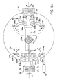
- Fig. 1A one of the pairs of wrappers 20/30 of the fourth process wheel 11 is illustrated in side view. It will be understood that the fourth process wheel 11 is situated at right angles to the plane of the drawing, the illustrated lollipop L with the stick S 1 being situated parallel to the centre axis S4.
- the lollipop holders 50 are illustrated diagrammatically and are clamped radially on the lollipop head K 1 by means of clamping jaws 50a, 50b while clamping the film/foil sheet F 1 present in tubular form in between.
- the longitudinal seam of the film/foil sheet runs parallel to the stick S 1 .
- the left-hand wrapper 20 comprises a holder 28 with two arms 21a, 21b, which are pivotably attached to the holder 28 at 22a, 22b and are provided with toothings 23a, 23b at that end. In a manner known per se, these toothings are in engagement with a toothed rack (not shown), which can be moved to and fro in the direction parallel to the stick S 1 . As a result of this movement, the arms 21a, 21b will rotate in the direction L, between a radially projecting, non-operating position, illustrated in the figure, and a closed, operating position.
- the wrapping arms 21a, 21b are provided with clamping panels 24a, 24b, with which a film/foil tube can be clamped flat.
- the wrapper 30 is constructed in a similar way and has a holder 38 with two wrapping arms 31a, 31b, which are pivotably attached to the holder 38 at the location of pivots 32a, 32b, and are there provided with toothings 33a, 33b, which engage again in a toothed rack in a manner known per se, which toothed rack can be moved to and fro in a direction parallel to the stick S 1 .
- the wrapping arms 31a, 31b are provided with clamping panels 34a, 34b, with which a film/foil tube can be clamped flat.
- Both holders 28, 38 are rotatable in the direction K, about a centre axis parallel to the stick S 1 , and to this end are provided with toothed wheels 25, 35, the teeth 26, 36 of which are in permanent engagement with an inner toothing 41 on a fixedly arranged ring 40, see Fig. 2A (for toothed wheel 25: toothed wheel 35 is driven in a similar fashion).
- the holders 28, 38 are mounted so as to be rotatable about their centre axes in the rotating section of the fourth process wheel 11. During rotation of the fourth process wheel 11, the teeth 26, 36 of the toothed wheels 25, 35 will therefore run along the fixed annular toothing 41, so that the holders 28, 38 and thus the wrappers 20, 30 are rotated in the direction K.
- twisting arms 21a, 21b remain in the projecting position, they will follow a garland-like path V during the rotation, as is illustrated diagrammatically in Fig. 2 .
- the number of such turning positions can be larger or smaller, depending on the ratio of the diameter of the toothings 41 and 26, 36.
- a coil 62 is arranged at the location of one of these turning positions of arms 21b.
- This coil 62 forms part of a heating device 60, placed in a stationary position near the fourth process wheel 11, as illustrated diagrammatically in Fig. 1 .
- the coil 62 forms part of an induction heating device 60, illustrated in more detail in Fig. 2 , comprising an induction heating unit 67, controlled by a control unit 66, from where a tube 63a,b runs which forms a coil 62 with turns 64.
- the coil 62 is directed exactly radially relative to the fourth process wheel 11.
- the tube 63 is made of copper, electrically conductive material, and is of hollow construction, so that a coolant flow can run via tube leg 63a, the coil 62 and back via tube leg 63b.
- the tubes 63a, 63b continue on the other end of the induction device 60, with tubes 65a, 65b, which lead to an induction device 61, where the coolant is cooled in the tube.
- the cooling unit 61 is electrically insulated from the induction heating unit 67.
- the coil 62 is positioned such that it can accommodate the clamping panel 24b of the wrapper 20 in its entirety, without contacting it. This is illustrated in more detail in Fig. 2B .
- the clamping panel 24b attached to the wrapping arm 21b, is provided with a metal insert 27b, fixedly clamped in a slot 29 made in the clamping panel 24b.
- the clamping panel 24b is furthermore made from a suitable plastic material.
- the metal insert 27b can be made from RVS430, ferritic stainless steel.
- the insert 27b is provided with a slot 27c for a lollipop stick, similar to the clamping panel 24a opposite.
- the metal is surrounded by the plastic of the clamping panel 24b in the lateral and backward direction and thus insulated.
- the packaging device 1 furthermore comprises a fixedly arranged infrared sensor 80, which is positioned on the periphery of the movement path such that the clamping panel 24b comes within its measuring range.
- the infrared sensor 80 is connected by a line 81 to the control unit 66 in order to emit measurement signals thereto which are indicative of the temperature of the insert 27b of the clamping panel 24b. These are stored in a shift register 82 in the control unit 66.
- the infrared sensor 80 is arranged four positions upstream of the heating coil 62.
- the infrared sensor 80 could for example also be arranged two positions further downstream if that does not impede the introduction of the packaging film/foil and the lollipop.
- the number of positions of the shift register 82 is equal to that number of positions, in this example therefore four positions.
- Fig. 5A shows the - in this case 10 - pairs of clamping panels 24a,b (positions a-j), with the direction of movement F being shown by way of indication.
- the clamping panel pair 24a,b of position f is then at the coil 62.
- a new measurement is taken on a clamping panel 24b.
- the control unit 66 is connected via input 72 to a control panel 71 with which the desired value for the temperature for the insert 27b, the heating body can be input into the control unit 66.
- the control unit 66 furthermore comprises a port 69a, for the line 81 leading from the infrared sensor 80 to the shift register 82.
- the port 69b is connected to an induction heating unit 67 which activates the coil 62 via line 63a,b.
- control unit 66 in which every measured value can be stored, at least until the next heating cycle of the respective clamping jaw, it is thus in principle possible to heat each clamping jaw separately up to a desired temperature according to an individually adapted control of the heating means, in this case using the induction coil.
- the induction heating unit 67 in order to energize the induction coil 62 at the observed differential temperature, based on a comparison of the measured value stored in the shift register 82 for position b and the desired value, for example 130°C, proportionally, according to power and/or time.
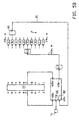
- Fig. 5B is identical to Fig. 5A except that it has been extended by a shift register 70, in which one or more values can be stored via port 68b for each position a-j relating to the state of the control unit, in particular the history of the state of the control system.
- the control unit 66 is able to read out the relevant information via port 68a and use it for the control of the induction heating device 67, also on the basis of the most recent measured value of infrared sensor 80 for the relevant position. Value(s) representative of the respective control of the induction heating device 67 are stored in the shift register 70, for use in later cycles for the relevant position.
- each separate clamping panel 24b with an insert 27b can be achieved, not only with minimum deviations between the positions themselves, but also for each position over time.
- the lollipops with film/foil sheet hanging from the head are received in the holders 50a,b of the fourth process wheel 11.
- the film/foil sheet can be folded around the head to form a tube.
- the two wrappers 20, 30 are not yet active, but hot air pressed into section II, which, using means (not shown), such as pipes bent in accordance with the path of the film/foil sheet around the head, will be delivered in a directed manner to the portion of the film/foil sheet which protrudes from the head on the end remote from the stick, will ensure that the film/foil sheet is heated on the side of the head remote from the sticks.
- the clamping panel 24b of the wrapper 20, which follows the path V, will move into and out of the coil 62.
- the induction coil 62 is energized electrically by the induction heating device 60, as a result of which a magnetic field is generated within the coil 62.
- the magnetic field will heat the metal insert 27b sufficiently for sealing purposes.
- the wrappers 20 and 30 are moved to the operating position by means which are not shown (the aforementioned toothed racks), the clamping panels 24a, 24b and 34a, 34b clamping the film/foil sheet F 1 such that it is flat.
- the clamping panels 24a, 24b and 34a, 34b clamping the film/foil sheet F 1 such that it is flat.
- the preheated film/foil material will ensure that the twisted film/foil material between the clamping panels 34a, 34b and the head K 1 is heat-sealed. This is the end of the sealing and wrapping section III, and the double-twisted, packaged lollipop can be dispensed in section IV.
- the metal insert 27b is insulated by the plastic material against the clamping panel 24b towards the sides which are not to be used, it will be possible to retain the heat in the insert 27b to a large degree and during the next insertion in the induction coil 62, it will only need to be reheated, as has been explained above.
- the diffusion of heat in the drum is in this case limited to a minimum.
Landscapes
- Engineering & Computer Science (AREA)
- Mechanical Engineering (AREA)
- Physics & Mathematics (AREA)
- Thermal Sciences (AREA)
- Package Closures (AREA)
- Basic Packing Technique (AREA)
Description
- The invention relates to a device and a method for packaging items, in particular confectionery, such as lollipops.
- It is known to package lollipops in sheets of packaging material, such as plastic film. In one embodiment, which is known as bunch-wrap packaging, the lollipops are held in stick clamps which are arranged on a rotatable drum. A sheet is positioned at the head side of the lollipops, then folded over and around the head and wrapped and heat-sealed on the stick side of the head. In this case, two rotatable arms provided with heated pressing ends, the arm ends, as well as a stick clamp which rotates the lollipop together with the folded sheet. The heating of the arms is effected by means of a supply conductor, which is connected by means of a movable coupling to a power supply which is fixed to the machine.
- Furthermore, it is known, from
WO-A-03/086871 - It is an object of the invention to provide a device and a method of the type mentioned in the preamble with which the heat-sealing of the packaging can be controlled to a large degree.
- It is an object of the invention to provide a device and a method of the type mentioned in the preamble with which the heat-sealing of the packaging can be carried out with a substantially low degree of malfunction.
- It is an object of the invention to provide a device and a method of the type mentioned in the preamble with which the heat-sealing of the packaging can be carried out in an efficient manner.
- In order to achieve at least one of these objects, the invention provides, according to one aspect, a device for packaging items, in particular confectionery, such as for example lollipops, comprising a packaging conveyor, such as a rotatably driven drum, having a series of holders rotating along a movement path for holding each item and its associated packaging sheet securely while conveying, a feed station for feeding the items and the packaging sheets to the packaging conveyor and a discharge station for discharging the items packaged on the conveyor, the packaging conveyor being provided with means for closing the packaging sheet on the respective item and with a series of heat-sealing means co-rotating with the holders for heat-sealing the closed packaging by supplying heat, each of the heat-sealing means comprising a sheet gripper which is provided with a heating body, the device furthermore comprising means for heating each heating body and means for controlling the heating means, the control means being designed for controlling the heating means for each heating body separately.
- By measuring the temperature of the heating means separately for each heating means and controlling the temperature on the basis of the separate measurement, it is possible to achieve a temperature which is as optimum as possible for each packaging step while taking individual circumstances into account. It is not necessary to use a single, possibly non-representative selection measurement for a plurality of heat-sealing means, as with the known device. This makes it possible to prevent differences in the quality of the closures of successive articles to a large degree.
- In one embodiment, the control means are provided with a first memory for storing a desired value for the temperature of the heating bodies, the device furthermore comprising means for measuring the temperature of each heating body, the control means being designed for controlling the heating means for that heating body based on the result of a comparison between the desired value and the last measured value of a heating body.
- In a further embodiment thereof, the control means comprise a control system and a second memory for discrete storage of values which are indicative of the historic state of the control system of a heating element, the control system being designed for controlling the heating means for said heating body based on the values for the historic state of the control system for the relevant heating body, the desired value and the last measured value of the relevant heating body. Thus, the reaction of that heating body to the heating can be taken into account when controlling the heating body, and therefore specific features of that heating body can be allowed for, such as a different weight.
- In one embodiment, the control means comprise a separate control system for each heating body, which allows each heating body to be controlled in an optimum manner.
- In one alternative embodiment, the control means comprise one control system for discretely and sequentially controlling the various heating bodies. When sequentially controlling the various heating bodies, it is thus possible to make considerable savings in the number of control systems. In one embodiment, the second memory is in this case designed for discrete storage of the values for the historic state of the control system for the various heating bodies, the second memory making the values of the historic state of each individual heating body sequentially available to the control system for sequentially controlling the various heating bodies.
- In one embodiment, the measuring means are stationary relative to the movement path of the holders, in particular on the outside of this path.
- The measuring means may be designed for contactless measurement of the temperature of the heating bodies. In one embodiment, the heating means are designed for contactless heating, from outside, of the heating bodies.
- The heating means may be stationary relative to the movement path of the holders. In one embodiment, the heating means and the measuring means are placed at regular intervals along the movement path of the holders. This makes it possible to at least reduce a possible interference between the heating by the heating means and the temperature measurement by the measuring means.
- In one embodiment, each sheet gripper with heating body can be moved between a non-operating position and an operating position, the heating means being arranged such that heat is supplied to the heating body when the sheet gripper is in the non-operating position. The measuring means may in this case be arranged such that they measure the temperature of the heating body when the sheet grippers are in the non-operating position.
- The packaging conveyor may be provided with wrapping means for forming a twisted end section of the packaging sheet while packaging the respective item and the heat-sealing means are arranged such that they heat-seal the twisted section or an adjoining region of the packaging sheet by supplying heat. Such wrapping means and heat-sealing means may be provided for each holder, the wrapping means and heat-sealing means preferably being designed such that they can operate during conveying thereof through the packaging conveyor.
- The sheet grippers may comprise pairs of clamping arms which are arranged on the packaging conveyor so as to be able to rotate about an individual rotation shaft, the path of the rotation shaft being situated at a shortest distance from the heating means which is smaller than the clamping arm length. The clamping arms can in this case be moved between an operating or clamping position directed at the rotation shaft and a projecting position or non-operating position directed away from the rotation shaft, the heating means being arranged in a section of the heat-sealing means, in which the clamping arms are in the projecting position, in which they extend preferably radially relative to the rotation shaft. In one embodiment, only one of the clamping arms is provided with a heating body.
- The clamping arms may be rotatable about their rotation shaft in a direction counter to the direction of rotation of the packaging conveyor.
- The heating means may comprise induction means for heating the heating body by means of induction. The induction means may comprise a stationary induction coil which is arranged in the movement path of the sheet gripper. The induction coil may be arranged such that the coil shaft is transverse to the movement path of the holders.
- In one embodiment, the sheet gripper also forms part of the wrapping means.
- The sheet gripper may be provided with a layer of heat-insulating material which protects the heating body in a direction other than the clamping direction.
- In one embodiment, the holders are designed for holding lollipops provided with a stick and a head.
- The sheet gripper may be arranged such that it operates on the side of the lollipop head facing the stick, such as for a bunchwrap-machine.
- If wrapping means and heat-sealing means are also positioned on the side of the head remote from the stick, the device is suitable for double twist-wraps.
- According to a preferred aspect, the invention provides a device for packaging items, in particular confectionery, such as for example lollipops, comprising a packaging conveyor having a series of holders for holding each item and its associated packaging sheet securely during conveying, a feed station for feeding the items and the packaging sheets to the packaging conveyor and a discharge station for discharging the items packaged on the conveyor, the packaging conveyor being provided with means for closing the packaging sheet on the respective item and with a series of heat-sealing means co-rotating with the holders for heat-sealing the closed packaging by supplying heat, each of the heat-sealing means comprising a sheet gripper which is provided with a heating body, the device furthermore comprising means for heating each heating body as well as means for measuring the temperature of each heating body and means for controlling the heating means based on the measuring means, the measuring means being designed for contactlessly measuring the temperature of each heating body.
- Thereby, the temperature can be measured without deformation and/or friction, thus making it possible to increase a fault-free period of operation.
- According to a further preferred aspect, the invention provides a device for packaging items, in particular confectionery, such as for example lollipops, comprising a packaging conveyor having a series of holders for holding each item and its associated packaging sheet securely during conveying, a feed station for feeding the items and the packaging sheets to the packaging conveyor and a discharge station for discharging the items packaged on the conveyor, the packaging conveyor being provided with means for closing the packaging sheet on the respective item and with a series of heat-sealing means co-rotating with the holders for heat-sealing the closed packaging by supplying heat, each of the heat-sealing means comprising a sheet gripper which is provided with a heating body, the device furthermore comprising means for heating the heating body of at least one of the heat-sealing means, as well as means for measuring the temperature of that heating body and means for controlling the heating means based on the measuring means, the measuring means being arranged in a stationary position relative to the packaging means.
- Thus, the measuring means can be arranged, for example outside the moving parts of the packaging conveyor, which measuring means are generally accommodated on a rotation drum. Fewer components are required for measuring the temperature. Measuring the temperature can be effected in a relatively simple manner using relatively stationary components which are thus simpler and less susceptible to failure.
- In this case as well, the measuring means may be designed for contactlessly measuring the temperature of the heating body.
- According to a further preferred aspect, the invention provides a device for packaging items, in particular confectionery, such as for example lollipops, comprising a packaging conveyor having a series of holders for holding each item and its associated packaging sheet securely during conveying, a feed station for feeding the items and the packaging sheets to the packaging conveyor and a discharge station for discharging the items packaged on the conveyor, the packaging conveyor being provided with means for closing the packaging sheet on the respective item and with a series of heat-sealing means co-rotating with the holders for heat-sealing the closed packaging by supplying heat, each of the heat-sealing means comprising a sheet gripper which is provided with a heating body, the device furthermore comprising means for heating each heating body and means for controlling the heating means, the control means being provided with a memory for storing a desired value of the temperature of the heating bodies, the device furthermore comprising means for measuring the temperature of each heating body, the control means furthermore comprising a memory for discrete storage of the measured values of the heating bodies, the control means being designed for controlling the heating means for that heating body based on the result of a comparison between the desired value and the last measured value of a heating body.
- The invention will be explained with reference to a number of exemplary embodiments illustrated in the attached drawings, in which:
-
Fig. 1 shows a diagrammatic front view of a device for the double-twist packaging of lollipops, provided with a device according to the invention, in an exemplary embodiment; -
Fig. 1A shows a diagrammatic side view of a unit for double-twist packaging a lollipop in the device fromFig. 1 ; -
Fig. 2 shows a diagrammatic view of a measuring and heating device for the device fromFig. 1 ; -
Fig. 2A shows a cross section of the illustration inFig. 2 ; -
Fig. 2B shows a detail of the illustration inFig. 2 ; -
Figs. 3A-C shows successive views in three directions of a twist clamp in the device fromFig. 1 ; -
Fig. 4 shows a diagrammatic view of a measuring and heating device for the device according toFig. 2 ; and -
Figs. 5A and5B show diagrammatic representations of two possible setups for the temperature measurement and heating control in the device from the preceding figures. - The
packaging device 1 inFigures 1 et seq. comprises aframe 2 which is placed on abase 100. Thedevice 1 comprises asupply container 3 for lollipops provided with a stick and a head, supplied in bulk in the direction A. At its bottom end, the container changes into a passage which has a shakingslope 5/6 on its bottom side which passes the lollipops in a stream in the direction B to adistribution disc 7 rotatable in the direction C along a vertical centre line S1. Thedistribution disc 7 has a relatively large surface, on which the lollipops supplied in bulk can be spread out. Thedistribution disc 7 is provided on the edge with holding spaces for the head of the lollipops and with radially outwardly extending slots for the sticks thereof. The lollipops with lollipop sticks are brought into an orientation with the sticks directed radially outwardly and then retained with the aid of means (not shown), which are known per se. On the edge of thedistribution disc 7, there is a second process wheel 8, which is rotatable in the direction D about a horizontal centre axis S2. Stick clamps are arranged on the second process wheel, which grasp the lollipops by their sticks and lift them from thedistribution disc 7. - Downstream of the second process wheel 8, a
third process wheel 9 is arranged which rotates in the direction E about the centre axis S3. A series of lollipop holders is arranged on thethird process wheel 9, at each of which a film/foil sheet clamp is positioned. A film/foil feed station 10 is positioned at thethird process wheel 9, in which a roll of film/foil sheet material can be placed and unwound and can be cut into separate sheets F1, delivered intermittently to thethird process wheel 9. - Downstream of the
third process wheel 9, viewed in processing direction, afourth process wheel 11 is disposed, which is rotatably driven in the direction F about the centre axis S4. Thefourth process wheel 11 is provided with a series ofco-rotating lollipop holders 50 and a series of co-rotating wrappers, as well as heat-sealing means for heat-sealing the two twisted ends of the film/foil packaging sheet on the lollipop. - Lollipops packaged in the
fourth process wheel 11 are passed on to adischarge wheel 12, which rotates in the direction G and can deliver the lollipops to adischarge 14 in order for them to be discharged in the direction J. - In
Fig. 1A , one of the pairs ofwrappers 20/30 of thefourth process wheel 11 is illustrated in side view. It will be understood that thefourth process wheel 11 is situated at right angles to the plane of the drawing, the illustrated lollipop L with the stick S1 being situated parallel to the centre axis S4. - The
lollipop holders 50 are illustrated diagrammatically and are clamped radially on the lollipop head K1 by means of clampingjaws - The left-
hand wrapper 20 comprises aholder 28 with twoarms holder 28 at 22a, 22b and are provided withtoothings arms - At their ends, the wrapping
arms panels - The
wrapper 30 is constructed in a similar way and has aholder 38 with two wrappingarms holder 38 at the location ofpivots toothings - At their ends, the wrapping
arms panels - Both
holders toothed wheels teeth inner toothing 41 on a fixedly arrangedring 40, seeFig. 2A (for toothed wheel 25:toothed wheel 35 is driven in a similar fashion). - The
holders fourth process wheel 11. During rotation of thefourth process wheel 11, theteeth toothed wheels annular toothing 41, so that theholders wrappers - If the twisting
arms Fig. 2 . In the radially outermost positions, there will be a short moment where they will not move in the peripheral direction, but instead their radially outward movement will change into a radially inward movement. It should be noted that the number of such turning positions can be larger or smaller, depending on the ratio of the diameter of thetoothings - As can be seen in
Fig. 2 , acoil 62 is arranged at the location of one of these turning positions ofarms 21b. Thiscoil 62 forms part of aheating device 60, placed in a stationary position near thefourth process wheel 11, as illustrated diagrammatically inFig. 1 . - The
coil 62 forms part of aninduction heating device 60, illustrated in more detail inFig. 2 , comprising aninduction heating unit 67, controlled by acontrol unit 66, from where atube 63a,b runs which forms acoil 62 withturns 64. Thecoil 62 is directed exactly radially relative to thefourth process wheel 11. Thetube 63 is made of copper, electrically conductive material, and is of hollow construction, so that a coolant flow can run viatube leg 63a, thecoil 62 and back viatube leg 63b. Thetubes induction device 60, withtubes induction device 61, where the coolant is cooled in the tube. The coolingunit 61 is electrically insulated from theinduction heating unit 67. - The
coil 62 is positioned such that it can accommodate theclamping panel 24b of thewrapper 20 in its entirety, without contacting it. This is illustrated in more detail inFig. 2B . - As can be seen in
Figs. 3A-C , the clampingpanel 24b, attached to thewrapping arm 21b, is provided with ametal insert 27b, fixedly clamped in aslot 29 made in theclamping panel 24b. The clampingpanel 24b is furthermore made from a suitable plastic material. Themetal insert 27b can be made from RVS430, ferritic stainless steel. In this case, theinsert 27b is provided with aslot 27c for a lollipop stick, similar to theclamping panel 24a opposite. - The metal is surrounded by the plastic of the
clamping panel 24b in the lateral and backward direction and thus insulated. - The
packaging device 1 furthermore comprises a fixedly arrangedinfrared sensor 80, which is positioned on the periphery of the movement path such that the clampingpanel 24b comes within its measuring range. Theinfrared sensor 80 is connected by aline 81 to thecontrol unit 66 in order to emit measurement signals thereto which are indicative of the temperature of theinsert 27b of theclamping panel 24b. These are stored in ashift register 82 in thecontrol unit 66. - As illustrated in
Fig. 5 , theinfrared sensor 80 is arranged four positions upstream of theheating coil 62. Theinfrared sensor 80 could for example also be arranged two positions further downstream if that does not impede the introduction of the packaging film/foil and the lollipop. The number of positions of theshift register 82 is equal to that number of positions, in this example therefore four positions. -
Fig. 5A shows the - in this case 10 - pairs of clampingpanels 24a,b (positions a-j), with the direction of movement F being shown by way of indication. The clampingpanel pair 24a,b of position f is then at thecoil 62. At the location of position b, a new measurement is taken on aclamping panel 24b. - The
control unit 66 is connected viainput 72 to acontrol panel 71 with which the desired value for the temperature for theinsert 27b, the heating body can be input into thecontrol unit 66. - The
control unit 66 furthermore comprises aport 69a, for theline 81 leading from theinfrared sensor 80 to theshift register 82. Theport 69b is connected to aninduction heating unit 67 which activates thecoil 62 vialine 63a,b. - Using the
control unit 66, in which every measured value can be stored, at least until the next heating cycle of the respective clamping jaw, it is thus in principle possible to heat each clamping jaw separately up to a desired temperature according to an individually adapted control of the heating means, in this case using the induction coil. Thus, it is possible to store the measured value for position b, for example, and when position b has arrived at thecoil 62, to control theinduction heating unit 67 in order to energize theinduction coil 62 at the observed differential temperature, based on a comparison of the measured value stored in theshift register 82 for position b and the desired value, for example 130°C, proportionally, according to power and/or time. In a similar manner, the other clamps of the positions a and c-j are heated in turn, depending on the temperature measured for these individual clamping jaws thereof byinfrared sensor 80 on therelevant inserts 27b. Such an arrangement may be feasible if theinserts 27b of all clampingpanels 24b are exactly identical to one another. -
Fig. 5B is identical toFig. 5A except that it has been extended by ashift register 70, in which one or more values can be stored viaport 68b for each position a-j relating to the state of the control unit, in particular the history of the state of the control system. Thecontrol unit 66 is able to read out the relevant information viaport 68a and use it for the control of theinduction heating device 67, also on the basis of the most recent measured value ofinfrared sensor 80 for the relevant position. Value(s) representative of the respective control of theinduction heating device 67 are stored in theshift register 70, for use in later cycles for the relevant position. - This makes a control system using a kind of learning process possible for each position; if the measured temperature in one rotation for a specific position is lower or higher than in the previous rotation, this may be noticed by the
control device 66 and the control of theinduction heating device 67 can subsequently be adjusted. - As a result thereof, an accurate heating of each
separate clamping panel 24b with aninsert 27b can be achieved, not only with minimum deviations between the positions themselves, but also for each position over time. - In use, as diagrammatically illustrated in
Fig. 2 , the lollipops with film/foil sheet hanging from the head, the bending axis of which is parallel to the stick S1, at the beginning of the section I, are received in theholders 50a,b of thefourth process wheel 11. - Using means not shown in any more detail, the film/foil sheet can be folded around the head to form a tube. In the meantime, the two
wrappers panel 24b of thewrapper 20, which follows the path V, will move into and out of thecoil 62. Theinduction coil 62 is energized electrically by theinduction heating device 60, as a result of which a magnetic field is generated within thecoil 62. By suitable choice of the components of the induction heating device, the magnetic field will heat themetal insert 27b sufficiently for sealing purposes. - As soon as the clamping
panel 24b is moved out of thecoil 62 again, thewrappers panels clamps heated insert 27b ensuring that the film/foil material is heat-sealed locally at the stick S1. On the other side, the preheated film/foil material will ensure that the twisted film/foil material between the clampingpanels - As the
metal insert 27b is insulated by the plastic material against the clampingpanel 24b towards the sides which are not to be used, it will be possible to retain the heat in theinsert 27b to a large degree and during the next insertion in theinduction coil 62, it will only need to be reheated, as has been explained above. The diffusion of heat in the drum is in this case limited to a minimum.
Claims (27)
- Device for packaging items, in particular confectionery, such as for example lollipops, comprising a packaging conveyor (11) having a series of holders (50) rotating along a movement path for holding each item and its associated packaging sheet (F1) securely during conveying, a feed station for feeding the items and the packaging sheets to the packaging conveyor and a discharge station (12) for discharging the items packaged on the conveyor, the packaging conveyor (11)being provided with means (20, 30) for closing the packaging sheet on the respective item and with a series of heat-sealing means co-rotating with the holders (50) for heat-sealing the closed packaging by supplying heat, each of the heat-sealing means comprising a sheet gripper which is provided with a heating body (27b), the device furthermore comprising means (60) for heating each heating body, characterized in, that it comprises means (66) for controlling the heating means (60), the control means (66)being designed for controlling the heating means (60) for each heating body (27b).
- Device according to Claim 1, in which the control means (66)are provided with a first memory for storing a desired value for the temperature of the heating bodies, the device furthermore comprising means for measuring the temperature of each heating body, the control means (66) being designed for controlling the heating means (60) for that heating body (27b) based on the result of a comparison between the desired value and the last measured value of a heating body.
- Device according to Claim 2, in which the control means (66) comprise a control system and a second memory for discrete storage of values which are indicative of the historic state of the control system of an individual heating body, the control system being designed for controlling the heating means for said heating body (27b)based on the values for the previous state of the control system for the relevant heating body, the desired value and the last measured value of the relevant heating body.
- Device according to Claim 3, in which the control means (60) comprise a separate control system for each heating body.
- Device according to Claim 3, in which the control means (60) comprise one control system for discretely and sequentially controlling the various heating bodies.
- Device according to Claim 3, 4 or 5, in which the measuring means (80)are stationary relative to the movement path of the holders.
- Device according to one of Claims 3, 6, in which the measuring means (80)are designed for contactless measurement of the temperature of the heating bodies (27b).
- Device according to one of the preceding claims, in which the heating means (60) are designed for contactless heating, from outside, of the heating bodies (27b).
- Device according to one of the preceding claims, in which the heating means (60)are stationary relative to the movement path of the holders (50).
- Device according to Claim 9 if dependent on Claim 6, in which the heating means (60) and the measuring means (80)are placed at regular intervals along the movement path of the holders.
- Device according to one of the preceding claims, in which each sheet gripper with heating body (27b)can be moved between a non-operating position and an operating position, the heat-supplying means (60)being arranged such that heat is supplied to the heating body when the sheet gripper is in the non-operating position, measuring means (80)preferably being arranged such that they measure the temperature of the heating body (27b)when the sheet grippers are in the non-operating position.
- Device according to one of the preceding claims, in which the packaging conveyor is provided with wrapping means (20, 30) for forming a twisted end section of the packaging sheet while packaging the respective item and the heat-sealing means are arranged such that they heat-seal the twisted section or an adjoining region of the packaging sheet by supplying heat.
- Device according to Claim 12, in which wrapping means (20, 30)and heat-sealing means are provided for each holder (50), the wrapping means (20, 30)and heat-sealing means preferably being designed such that they operate during conveying thereof through by the packaging conveyor.
- Device according to one of the preceding claims, in which the heat-supplying means (60)are placed on the outside of the movement path.
- Device according to one of the preceding claims, in which the sheet grippers comprise pairs of clamping arms (21a, 21b, 31a, 31b) which are arranged on the packaging conveyor so as to be able to rotate about an individual rotation shaft, the path of the rotation shaft being situated at a shortest distance from the heat-supplying means which is smaller than the clamping arm length.
- Device according to Claim 15, in which the clamping arms (21a, 21b, 31a, 31b) can be moved between an operating or clamping position directed at the rotation shaft and a projecting position or non-operating position directed away from the rotation shaft, the heat-supplying means (60)being arranged in a section of the heat-sealing means, in which the clamping arms (21a, 21b, 31a, 31b) are in the projecting position, in which they extend preferably radially relative to the rotation shaft.
- Device according to Claim 15 or 16, in which only one of the clamping arms (21a, 21b, 31a, 31b) is provided with a heating body (27b).
- Device according to Claim 15, 16 or 17, in which the clamping arms (21a, 21b, 31a, 31b) are rotatable about their rotation shaft in a direction counter to the direction of rotation of the packaging conveyor.
- Device according to one of the preceding claims, in which the heating means (60) comprise induction means for heating the heating body by means of induction.
- Device according to Claim 19, in which the induction means comprise a stationary induction coil (62)which is arranged in the movement path of the sheet gripper.
- Device according to Claim 20, in which the induction coil (62)is arranged such that the coil shaft is transverse to the movement path of the holders.
- Device according to one of the preceding claims, in which the sheet gripper also forms part of the wrapping means.
- Device according to one of the preceding claims, in which the packaging conveyor is a rotating driven drum.
- Devise according to one of the preceding claims, in which the sheet gripper may be provided with a layer of heat-insulating material which protects the heating body (27b) in a direction other than the clamping direction.
- Device according to one of the preceding claims, in which the holders (50) are designed for holding lollipops provided with a stick and a head.
- Device according to Claim 25, in which the sheet gripper is arranged such that it operates on the side of the lollipop head facing the stick.
- Device according to Claim 26, in which wrapping means and heat-sealing means are also positioned on the side of the head remote from the stick.
Applications Claiming Priority (3)
| Application Number | Priority Date | Filing Date | Title |
|---|---|---|---|
| NL1028769A NL1028769C2 (en) | 2005-04-14 | 2005-04-14 | Packaging device for confectionery, has sealing apparatus using pair of grippers and heating system provided with control unit |
| NL1031139A NL1031139C2 (en) | 2005-04-14 | 2006-02-13 | Device for packaging articles. |
| PCT/EP2006/061314 WO2006108781A1 (en) | 2005-04-14 | 2006-04-04 | Device for packaging items, in particular confectionery |
Publications (2)
| Publication Number | Publication Date |
|---|---|
| EP1874629A1 EP1874629A1 (en) | 2008-01-09 |
| EP1874629B1 true EP1874629B1 (en) | 2010-09-22 |
Family
ID=36572217
Family Applications (1)
| Application Number | Title | Priority Date | Filing Date |
|---|---|---|---|
| EP06725550A Expired - Lifetime EP1874629B1 (en) | 2005-04-14 | 2006-04-04 | Device for packaging items, in particular confectionery |
Country Status (9)
| Country | Link |
|---|---|
| US (1) | US7739860B2 (en) |
| EP (1) | EP1874629B1 (en) |
| AR (1) | AR053219A1 (en) |
| AT (1) | ATE482144T1 (en) |
| BR (1) | BRPI0610630B1 (en) |
| DE (1) | DE602006017051D1 (en) |
| NL (1) | NL1031139C2 (en) |
| TW (1) | TW200702241A (en) |
| WO (1) | WO2006108781A1 (en) |
Families Citing this family (12)
| Publication number | Priority date | Publication date | Assignee | Title |
|---|---|---|---|---|
| NL1026780C2 (en) * | 2004-08-04 | 2006-02-13 | Cfs Weert Bv | Transfer device for lollipops. |
| NL1028768C2 (en) | 2005-04-14 | 2006-10-17 | Cfs Weert Bv | Packing machine for lollipops and other confectionery. |
| ES2325090T5 (en) | 2006-04-20 | 2013-06-12 | Cfs Weert B.V. | Machine for the individualization of stick candies |
| DE602006015440D1 (en) | 2006-05-22 | 2010-08-26 | Cfs Weert Bv | Packaging machine for objects |
| EP1908573A1 (en) * | 2006-10-05 | 2008-04-09 | CFS Weert B.V. | Packaging machine with induction heated sealing body |
| DE102006050039A1 (en) * | 2006-10-24 | 2008-04-30 | Robert Bosch Gmbh | Packing machine for packing small-sized articles e.g. e.g. hard caramel, has heat-generating device provided for fixing twist wrap in region of constriction of packaging to prevent accidental opening of wrap |
| EP2228306B1 (en) * | 2009-03-12 | 2012-08-01 | CFS Weert B.V. | Packaging machine with induction heating and flux guide means |
| BR112016027134B1 (en) | 2014-05-20 | 2021-08-24 | Gea Food Solutions Weert B.V. | APPARATUS FOR THE PRODUCTION AND WRAPPING OF LOOPYS |
| JP6724426B2 (en) * | 2016-03-04 | 2020-07-15 | 澁谷工業株式会社 | Seal material welding device |
| DE102018209185B3 (en) | 2018-06-08 | 2019-10-02 | Theegarten-Pactec Gmbh & Co. Kg | Method and device for packaging small-sized articles in heat-sealable packaging material with a heatable holding element |
| DE102019220426A1 (en) | 2019-12-20 | 2021-06-24 | Theegarten-Pactec Gmbh & Co. Kg | Inductor for multi-lane packaging machines |
| CN117125296B (en) * | 2022-10-28 | 2026-03-03 | 浙江智味轩食品科技有限公司 | Lollipop binding and twisting packaging machine |
Family Cites Families (57)
| Publication number | Priority date | Publication date | Assignee | Title |
|---|---|---|---|---|
| US1809358A (en) * | 1928-02-23 | 1931-06-09 | Edward S Savage | Molding machine |
| GB328145A (en) | 1929-05-29 | 1930-04-24 | Alfred German Rose | Improvements in or relating to wrapping machines |
| GB374653A (en) | 1931-07-03 | 1932-06-16 | John Mackintosh And Sons Ltd | A new or improved fringing appliance applicable to machines for wrapping or parcelling confectionery or the like |
| GB406220A (en) | 1933-08-24 | 1934-02-22 | Albert Henkel Junior | Improvements in machines for moulding plastic substances |
| US2246243A (en) * | 1938-09-26 | 1941-06-17 | Package Machinery Co | Machine for wrapping lollipops |
| US2705857A (en) | 1953-07-28 | 1955-04-12 | F & F Lab Inc | Method of and apparatus for making wrapped candy suckers |
| US3038635A (en) * | 1959-03-20 | 1962-06-12 | Marlin B Rasmusson | Stick inserter for frozen confection machines |
| GB998643A (en) | 1962-11-05 | 1965-07-21 | Jack Oldham | Improvements in or relating to conveyor apparatus |
| GB1214983A (en) | 1967-12-02 | 1970-12-09 | Ben Edward Rasmusson | Improvements in or relating to non-refrigerator food products |
| US3741698A (en) | 1971-06-16 | 1973-06-26 | Dbm Industries Ltd | Stick injector with paper feed |
| US3851440A (en) | 1972-11-13 | 1974-12-03 | Fmc Corp | Packaging method |
| GB1469129A (en) * | 1974-06-12 | 1977-03-30 | Baker Perkins Holdings Ltd | Wrapping apparatus |
| US4008812A (en) * | 1975-09-15 | 1977-02-22 | Forster Mfg. Co., Inc. | Stick storage apparatus with automatic reject system for misaligned sticks |
| US4130936A (en) * | 1977-08-11 | 1978-12-26 | Champion International Corporation | Stick handling and inserting method and apparatus |
| US4459792A (en) * | 1981-05-13 | 1984-07-17 | Derckx Henricus A J M | Device for twisting a packing wrapping |
| BE890180A (en) | 1981-09-02 | 1982-03-02 | Aquarius Coenrardus H | IMPROVEMENTS IN MACHINERY FOR MOLDING CANDY, MORE SPECIAL LOLLIES |
| IT1156648B (en) | 1982-08-18 | 1987-02-04 | Risvin Ricerche Sviluppo Ind | CONTINUOUS MOVING WRAPPING EQUIPMENT CANDIES OR SIMILAR ITEMS IN THE SO-CALLED DOUBLE-FLAP WRAPPING LEAF |
| DK153663C (en) | 1983-04-14 | 1988-12-27 | Gram Brdr As | APPARATUS FOR USE BY RECOVERING ITEMS FROZEN IN FORMS IN A FREEZER |
| US4714419A (en) * | 1984-03-30 | 1987-12-22 | Nielsen A Lamont | Candy dispensing apparatus |
| US4729501A (en) * | 1987-04-10 | 1988-03-08 | Lowrance Thomas F | Flat stick automatic feeder apparatus |
| GB8814080D0 (en) | 1988-06-14 | 1988-07-20 | Baker Perkins Plc | Improvements in/relating to manufacture of lollipops |
| ES2010460A6 (en) | 1989-03-20 | 1989-11-01 | Escola Gallart Ramon | Confection filled with gasified caramel and method of producing same |
| US5715645A (en) | 1993-03-24 | 1998-02-10 | Ishida Co., Ltd. | Device for setting seal temperatures and packaging machine provided with same |
| US5108279A (en) | 1991-03-11 | 1992-04-28 | Apv Rosista, Inc. | Stick confection extraction apparatus |
| US5117613A (en) * | 1991-04-11 | 1992-06-02 | Tocco, Inc. | Induction heating and package sealing system and method |
| US5241807A (en) | 1992-02-26 | 1993-09-07 | Quick Howard E | Method and apparatus for wrapping lollipops and similar articles |
| DE4213830A1 (en) | 1992-04-28 | 1993-11-04 | Ahlbrandt Andreas | Induction heating for heating plastic coated metal foil lid of plastic container, e.g. bottle - using electric winding for prodn. of electromagnetic alternating field for welding or sealing of coating with wall of container outlet |
| US5450706A (en) * | 1993-05-24 | 1995-09-19 | Latini Machine Company, Inc. | Single twist bunch wrapping machine |
| JP2621016B2 (en) * | 1993-09-06 | 1997-06-18 | テンチ機械株式会社 | Twist packing machine |
| DE19502562A1 (en) | 1995-01-27 | 1996-08-01 | Pactec Verpackungsmaschinen Fa | Continuous system for wrapping goods in sheet material |
| IT1280413B1 (en) | 1995-04-13 | 1998-01-20 | Azionaria Costruzioni Acma Spa | METHOD AND UNIT FOR WELDING THE HEAD OF ELONGATED ENCLOSURES |
| IT1278193B1 (en) | 1995-05-10 | 1997-11-17 | Azionaria Costruzioni Acma Spa | METHOD AND UNIT FOR LONGITUDINAL WELDING OF TUBULAR ENVELOPES |
| JP3333925B2 (en) * | 1995-07-26 | 2002-10-15 | 株式会社フジキカイ | Vertical sealing device in bag making and filling machine |
| US5678390A (en) | 1995-10-17 | 1997-10-21 | Food Machinery Sales, Inc. | Horizontal form, fill, and seal packaging machine |
| DE19616989C1 (en) | 1996-04-27 | 1997-10-02 | Bosch Gmbh Robert | Device for separating and picking up sweets |
| ES2156353T3 (en) | 1996-11-15 | 2001-06-16 | Auto Mate Technologies Llc | SEALING UNIT OF INDUCTION COUPLINGS AND SEALING METHOD. |
| IT1292614B1 (en) * | 1997-06-10 | 1999-02-08 | Gd Spa | METHOD AND DEVICE FOR THE WELDING OF CERTAIN PORTIONS OF PACKAGING OF HEAT-SEALABLE MATERIAL OF PRODUCTS. |
| US6633480B1 (en) * | 1997-11-07 | 2003-10-14 | Kenneth J. Herzog | Air-cooled induction foil cap sealer |
| DE69820028T2 (en) * | 1998-04-15 | 2004-08-26 | Tetra Laval Holding & Finance S.A. | Method for monitoring the transverse welds in a packaging unit for the continuous forming of packages with liquid foods and packaging unit |
| EP0956776B1 (en) | 1998-05-13 | 2005-04-20 | Societe Des Produits Nestle S.A. | Process and apparatus for shaping of ice-confections |
| WO2000021835A1 (en) | 1998-10-15 | 2000-04-20 | Carugil, S.L. | Machine for wrapping lollipops |
| US6238616B1 (en) * | 1998-12-14 | 2001-05-29 | Timecaps Inc. | Method of manufacturing gelatin capsule containing powder or time release pellets |
| AU1968699A (en) | 1999-01-13 | 2000-08-01 | Carugil, S.L. | Refrigeration system for candy forming machines |
| GB0108682D0 (en) | 2001-04-06 | 2001-05-30 | Apv Uk | Lollipop manufacture |
| BR0309351B1 (en) * | 2002-04-18 | 2012-09-18 | machine for packing products. | |
| DE10217898A1 (en) | 2002-04-22 | 2003-11-06 | Theegarten Pactec Gmbh & Co Kg | Device and method for separating small items |
| DE10303726B3 (en) | 2003-01-30 | 2004-05-27 | Hosokawa Bepex Gmbh | Equipment inserting lollipop sticks in molds, includes rotor with internal stick ejector carrying pegs which first enter radial channels, then retract before rotor turns |
| DE10319829A1 (en) | 2003-05-03 | 2004-11-18 | Manfred Haiss | Machine supplying handles for e.g. lollipops, includes separator between magazine and conveyor, with holders for sticks |
| NL1023733C2 (en) | 2003-06-24 | 2004-12-28 | C F S Weert B V | Packing machine. |
| NL1024700C2 (en) | 2003-11-04 | 2005-05-09 | C F S Weert B V | Lolly machine. |
| US7210926B2 (en) * | 2003-11-10 | 2007-05-01 | General Electric Company | Formable sheets for medical applications and methods of manufacture thereof |
| DE102004033338B4 (en) * | 2004-07-09 | 2010-12-09 | Airbus Deutschland Gmbh | Spray device with droplet retention and method |
| NL1028768C2 (en) | 2005-04-14 | 2006-10-17 | Cfs Weert Bv | Packing machine for lollipops and other confectionery. |
| NL1028769C2 (en) | 2005-04-14 | 2006-10-17 | Cfs Weert Bv | Packaging device for confectionery, has sealing apparatus using pair of grippers and heating system provided with control unit |
| NL1029303C2 (en) | 2005-06-21 | 2010-07-27 | C F S Weert B V | APPARATUS AND METHOD FOR MAKING CAST LOLLIES. |
| WO2007121930A1 (en) | 2006-04-20 | 2007-11-01 | Cfs Weert B.V. | Singling machine for lollipops |
| DE602006015440D1 (en) | 2006-05-22 | 2010-08-26 | Cfs Weert Bv | Packaging machine for objects |
-
2006
- 2006-02-13 NL NL1031139A patent/NL1031139C2/en not_active IP Right Cessation
- 2006-04-04 WO PCT/EP2006/061314 patent/WO2006108781A1/en not_active Ceased
- 2006-04-04 BR BRPI0610630-7A patent/BRPI0610630B1/en not_active IP Right Cessation
- 2006-04-04 DE DE602006017051T patent/DE602006017051D1/en not_active Expired - Lifetime
- 2006-04-04 AT AT06725550T patent/ATE482144T1/en not_active IP Right Cessation
- 2006-04-04 EP EP06725550A patent/EP1874629B1/en not_active Expired - Lifetime
- 2006-04-04 US US11/911,293 patent/US7739860B2/en not_active Expired - Lifetime
- 2006-04-12 AR ARP060101475A patent/AR053219A1/en active IP Right Grant
- 2006-04-12 TW TW095112933A patent/TW200702241A/en unknown
Also Published As
| Publication number | Publication date |
|---|---|
| TW200702241A (en) | 2007-01-16 |
| US7739860B2 (en) | 2010-06-22 |
| NL1031139A1 (en) | 2006-10-17 |
| NL1031139C2 (en) | 2007-11-14 |
| BRPI0610630B1 (en) | 2018-12-26 |
| WO2006108781A1 (en) | 2006-10-19 |
| DE602006017051D1 (en) | 2010-11-04 |
| EP1874629A1 (en) | 2008-01-09 |
| BRPI0610630A2 (en) | 2010-07-13 |
| US20090241476A1 (en) | 2009-10-01 |
| AR053219A1 (en) | 2007-04-25 |
| ATE482144T1 (en) | 2010-10-15 |
Similar Documents
| Publication | Publication Date | Title |
|---|---|---|
| US8397476B2 (en) | Device for packaging items | |
| US7739860B2 (en) | Device for packaging items, in particular confectionery | |
| EP2228306B1 (en) | Packaging machine with induction heating and flux guide means | |
| US9309016B2 (en) | Automatic container orientation systems and methods | |
| ES2340635T3 (en) | PROCEDURE AND DEVICE FOR PACKING ARTICLES OF SMALL DIMENSIONS. | |
| CN104781146A (en) | High-efficiency packaging method for packaging, especially small-sized products, and high-efficiency packaging plant for, inter alia, carrying out the method | |
| CA1224754A (en) | Method of applying plastic labels on glass containers | |
| JPS6028732B2 (en) | Equipment for heat sealing packaging materials and similar items | |
| CN111295338A (en) | Machine for forming filter bags for infused products | |
| CN107934515A (en) | Container production plant with diverter wheel at coating station | |
| MXPA04010286A (en) | Machine for packaging products. | |
| RU2314236C2 (en) | Packet making and sealing device | |
| WO2008040480A2 (en) | Packaging machine with induction heated sealing body | |
| US20190009937A1 (en) | An apparatus and a method for packaging piece goods and in particular containers | |
| NL1028769C2 (en) | Packaging device for confectionery, has sealing apparatus using pair of grippers and heating system provided with control unit | |
| JP2019202831A (en) | Article conveying device | |
| JP2013209156A (en) | Method and unit for forming tubular length of web material in labelling machine | |
| EP1201599A1 (en) | System for conveying objects to be processed | |
| JP4704183B2 (en) | Strip bag equipment | |
| JP4323030B2 (en) | Cartoning equipment | |
| KR200171045Y1 (en) | Winding packing apparatus in an automatic packaging machine | |
| JP2018144847A (en) | Packaging equipment | |
| KR20010007938A (en) | Supply apparatus of straw packing machine | |
| WO2018193485A1 (en) | A filling machine and a process for filling thermoplastic containers | |
| JP2006143349A (en) | Operating device and packaging equipment |
Legal Events
| Date | Code | Title | Description |
|---|---|---|---|
| PUAI | Public reference made under article 153(3) epc to a published international application that has entered the european phase |
Free format text: ORIGINAL CODE: 0009012 |
|
| 17P | Request for examination filed |
Effective date: 20071114 |
|
| AK | Designated contracting states |
Kind code of ref document: A1 Designated state(s): AT BE BG CH CY CZ DE DK EE ES FI FR GB GR HU IE IS IT LI LT LU LV MC NL PL PT RO SE SI SK TR |
|
| DAX | Request for extension of the european patent (deleted) | ||
| 17Q | First examination report despatched |
Effective date: 20090401 |
|
| GRAP | Despatch of communication of intention to grant a patent |
Free format text: ORIGINAL CODE: EPIDOSNIGR1 |
|
| RIN1 | Information on inventor provided before grant (corrected) |
Inventor name: VAN RENS, JOSEPH, JOHAN, MARIA |
|
| GRAS | Grant fee paid |
Free format text: ORIGINAL CODE: EPIDOSNIGR3 |
|
| GRAA | (expected) grant |
Free format text: ORIGINAL CODE: 0009210 |
|
| AK | Designated contracting states |
Kind code of ref document: B1 Designated state(s): AT BE BG CH CY CZ DE DK EE ES FI FR GB GR HU IE IS IT LI LT LU LV MC NL PL PT RO SE SI SK TR |
|
| REG | Reference to a national code |
Ref country code: GB Ref legal event code: FG4D |
|
| REG | Reference to a national code |
Ref country code: CH Ref legal event code: EP |
|
| REG | Reference to a national code |
Ref country code: IE Ref legal event code: FG4D |
|
| REF | Corresponds to: |
Ref document number: 602006017051 Country of ref document: DE Date of ref document: 20101104 Kind code of ref document: P |
|
| PG25 | Lapsed in a contracting state [announced via postgrant information from national office to epo] |
Ref country code: LT Free format text: LAPSE BECAUSE OF FAILURE TO SUBMIT A TRANSLATION OF THE DESCRIPTION OR TO PAY THE FEE WITHIN THE PRESCRIBED TIME-LIMIT Effective date: 20100922 Ref country code: AT Free format text: LAPSE BECAUSE OF FAILURE TO SUBMIT A TRANSLATION OF THE DESCRIPTION OR TO PAY THE FEE WITHIN THE PRESCRIBED TIME-LIMIT Effective date: 20100922 Ref country code: FI Free format text: LAPSE BECAUSE OF FAILURE TO SUBMIT A TRANSLATION OF THE DESCRIPTION OR TO PAY THE FEE WITHIN THE PRESCRIBED TIME-LIMIT Effective date: 20100922 |
|
| REG | Reference to a national code |
Ref country code: NL Ref legal event code: VDEP Effective date: 20100922 |
|
| REG | Reference to a national code |
Ref country code: ES Ref legal event code: FG2A Effective date: 20110208 |
|
| LTIE | Lt: invalidation of european patent or patent extension |
Effective date: 20100922 |
|
| PG25 | Lapsed in a contracting state [announced via postgrant information from national office to epo] |
Ref country code: SI Free format text: LAPSE BECAUSE OF FAILURE TO SUBMIT A TRANSLATION OF THE DESCRIPTION OR TO PAY THE FEE WITHIN THE PRESCRIBED TIME-LIMIT Effective date: 20100922 Ref country code: PL Free format text: LAPSE BECAUSE OF FAILURE TO SUBMIT A TRANSLATION OF THE DESCRIPTION OR TO PAY THE FEE WITHIN THE PRESCRIBED TIME-LIMIT Effective date: 20100922 |
|
| PG25 | Lapsed in a contracting state [announced via postgrant information from national office to epo] |
Ref country code: GR Free format text: LAPSE BECAUSE OF FAILURE TO SUBMIT A TRANSLATION OF THE DESCRIPTION OR TO PAY THE FEE WITHIN THE PRESCRIBED TIME-LIMIT Effective date: 20101223 Ref country code: SE Free format text: LAPSE BECAUSE OF FAILURE TO SUBMIT A TRANSLATION OF THE DESCRIPTION OR TO PAY THE FEE WITHIN THE PRESCRIBED TIME-LIMIT Effective date: 20100922 Ref country code: LV Free format text: LAPSE BECAUSE OF FAILURE TO SUBMIT A TRANSLATION OF THE DESCRIPTION OR TO PAY THE FEE WITHIN THE PRESCRIBED TIME-LIMIT Effective date: 20100922 |
|
| PG25 | Lapsed in a contracting state [announced via postgrant information from national office to epo] |
Ref country code: CZ Free format text: LAPSE BECAUSE OF FAILURE TO SUBMIT A TRANSLATION OF THE DESCRIPTION OR TO PAY THE FEE WITHIN THE PRESCRIBED TIME-LIMIT Effective date: 20100922 Ref country code: NL Free format text: LAPSE BECAUSE OF FAILURE TO SUBMIT A TRANSLATION OF THE DESCRIPTION OR TO PAY THE FEE WITHIN THE PRESCRIBED TIME-LIMIT Effective date: 20100922 Ref country code: PT Free format text: LAPSE BECAUSE OF FAILURE TO SUBMIT A TRANSLATION OF THE DESCRIPTION OR TO PAY THE FEE WITHIN THE PRESCRIBED TIME-LIMIT Effective date: 20110124 Ref country code: IS Free format text: LAPSE BECAUSE OF FAILURE TO SUBMIT A TRANSLATION OF THE DESCRIPTION OR TO PAY THE FEE WITHIN THE PRESCRIBED TIME-LIMIT Effective date: 20110122 Ref country code: RO Free format text: LAPSE BECAUSE OF FAILURE TO SUBMIT A TRANSLATION OF THE DESCRIPTION OR TO PAY THE FEE WITHIN THE PRESCRIBED TIME-LIMIT Effective date: 20100922 Ref country code: EE Free format text: LAPSE BECAUSE OF FAILURE TO SUBMIT A TRANSLATION OF THE DESCRIPTION OR TO PAY THE FEE WITHIN THE PRESCRIBED TIME-LIMIT Effective date: 20100922 Ref country code: SK Free format text: LAPSE BECAUSE OF FAILURE TO SUBMIT A TRANSLATION OF THE DESCRIPTION OR TO PAY THE FEE WITHIN THE PRESCRIBED TIME-LIMIT Effective date: 20100922 |
|
| PG25 | Lapsed in a contracting state [announced via postgrant information from national office to epo] |
Ref country code: BE Free format text: LAPSE BECAUSE OF FAILURE TO SUBMIT A TRANSLATION OF THE DESCRIPTION OR TO PAY THE FEE WITHIN THE PRESCRIBED TIME-LIMIT Effective date: 20100922 |
|
| PLBE | No opposition filed within time limit |
Free format text: ORIGINAL CODE: 0009261 |
|
| STAA | Information on the status of an ep patent application or granted ep patent |
Free format text: STATUS: NO OPPOSITION FILED WITHIN TIME LIMIT |
|
| 26N | No opposition filed |
Effective date: 20110623 |
|
| PG25 | Lapsed in a contracting state [announced via postgrant information from national office to epo] |
Ref country code: DK Free format text: LAPSE BECAUSE OF FAILURE TO SUBMIT A TRANSLATION OF THE DESCRIPTION OR TO PAY THE FEE WITHIN THE PRESCRIBED TIME-LIMIT Effective date: 20100922 |
|
| REG | Reference to a national code |
Ref country code: DE Ref legal event code: R097 Ref document number: 602006017051 Country of ref document: DE Effective date: 20110623 |
|
| PG25 | Lapsed in a contracting state [announced via postgrant information from national office to epo] |
Ref country code: MC Free format text: LAPSE BECAUSE OF NON-PAYMENT OF DUE FEES Effective date: 20110430 |
|
| REG | Reference to a national code |
Ref country code: CH Ref legal event code: PL |
|
| REG | Reference to a national code |
Ref country code: FR Ref legal event code: ST Effective date: 20111230 |
|
| PG25 | Lapsed in a contracting state [announced via postgrant information from national office to epo] |
Ref country code: CH Free format text: LAPSE BECAUSE OF NON-PAYMENT OF DUE FEES Effective date: 20110430 Ref country code: LI Free format text: LAPSE BECAUSE OF NON-PAYMENT OF DUE FEES Effective date: 20110430 Ref country code: FR Free format text: LAPSE BECAUSE OF NON-PAYMENT OF DUE FEES Effective date: 20110502 |
|
| REG | Reference to a national code |
Ref country code: IE Ref legal event code: MM4A |
|
| PG25 | Lapsed in a contracting state [announced via postgrant information from national office to epo] |
Ref country code: IE Free format text: LAPSE BECAUSE OF NON-PAYMENT OF DUE FEES Effective date: 20110404 |
|
| PG25 | Lapsed in a contracting state [announced via postgrant information from national office to epo] |
Ref country code: CY Free format text: LAPSE BECAUSE OF FAILURE TO SUBMIT A TRANSLATION OF THE DESCRIPTION OR TO PAY THE FEE WITHIN THE PRESCRIBED TIME-LIMIT Effective date: 20100922 Ref country code: LU Free format text: LAPSE BECAUSE OF NON-PAYMENT OF DUE FEES Effective date: 20110404 |
|
| PG25 | Lapsed in a contracting state [announced via postgrant information from national office to epo] |
Ref country code: TR Free format text: LAPSE BECAUSE OF FAILURE TO SUBMIT A TRANSLATION OF THE DESCRIPTION OR TO PAY THE FEE WITHIN THE PRESCRIBED TIME-LIMIT Effective date: 20100922 Ref country code: BG Free format text: LAPSE BECAUSE OF FAILURE TO SUBMIT A TRANSLATION OF THE DESCRIPTION OR TO PAY THE FEE WITHIN THE PRESCRIBED TIME-LIMIT Effective date: 20101222 |
|
| PG25 | Lapsed in a contracting state [announced via postgrant information from national office to epo] |
Ref country code: HU Free format text: LAPSE BECAUSE OF FAILURE TO SUBMIT A TRANSLATION OF THE DESCRIPTION OR TO PAY THE FEE WITHIN THE PRESCRIBED TIME-LIMIT Effective date: 20100922 |
|
| PGFP | Annual fee paid to national office [announced via postgrant information from national office to epo] |
Ref country code: GB Payment date: 20140423 Year of fee payment: 9 |
|
| GBPC | Gb: european patent ceased through non-payment of renewal fee |
Effective date: 20150404 |
|
| PG25 | Lapsed in a contracting state [announced via postgrant information from national office to epo] |
Ref country code: GB Free format text: LAPSE BECAUSE OF NON-PAYMENT OF DUE FEES Effective date: 20150404 |
|
| P01 | Opt-out of the competence of the unified patent court (upc) registered |
Effective date: 20230523 |
|
| PGFP | Annual fee paid to national office [announced via postgrant information from national office to epo] |
Ref country code: DE Payment date: 20240418 Year of fee payment: 19 |
|
| PGFP | Annual fee paid to national office [announced via postgrant information from national office to epo] |
Ref country code: ES Payment date: 20240517 Year of fee payment: 19 |
|
| PGFP | Annual fee paid to national office [announced via postgrant information from national office to epo] |
Ref country code: IT Payment date: 20240419 Year of fee payment: 19 |
|
| REG | Reference to a national code |
Ref country code: DE Ref legal event code: R119 Ref document number: 602006017051 Country of ref document: DE |
|
| PG25 | Lapsed in a contracting state [announced via postgrant information from national office to epo] |
Ref country code: DE Free format text: LAPSE BECAUSE OF NON-PAYMENT OF DUE FEES Effective date: 20251104 |
|
| PG25 | Lapsed in a contracting state [announced via postgrant information from national office to epo] |
Ref country code: IT Free format text: LAPSE BECAUSE OF NON-PAYMENT OF DUE FEES Effective date: 20250404 |
|
| REG | Reference to a national code |
Ref country code: ES Ref legal event code: FD2A Effective date: 20260526 |
|
| PG25 | Lapsed in a contracting state [announced via postgrant information from national office to epo] |
Ref country code: ES Free format text: LAPSE BECAUSE OF NON-PAYMENT OF DUE FEES Effective date: 20250405 |