EP1873418B1 - Drum brake with ceramic friction surfaces - Google Patents
Drum brake with ceramic friction surfaces Download PDFInfo
- Publication number
- EP1873418B1 EP1873418B1 EP07007064A EP07007064A EP1873418B1 EP 1873418 B1 EP1873418 B1 EP 1873418B1 EP 07007064 A EP07007064 A EP 07007064A EP 07007064 A EP07007064 A EP 07007064A EP 1873418 B1 EP1873418 B1 EP 1873418B1
- Authority
- EP
- European Patent Office
- Prior art keywords
- brake
- drum
- brake shoes
- wedge
- drum brake
- Prior art date
- Legal status (The legal status is an assumption and is not a legal conclusion. Google has not performed a legal analysis and makes no representation as to the accuracy of the status listed.)
- Expired - Fee Related
Links
Images

Classifications
-
- F—MECHANICAL ENGINEERING; LIGHTING; HEATING; WEAPONS; BLASTING
- F16—ENGINEERING ELEMENTS AND UNITS; GENERAL MEASURES FOR PRODUCING AND MAINTAINING EFFECTIVE FUNCTIONING OF MACHINES OR INSTALLATIONS; THERMAL INSULATION IN GENERAL
- F16D—COUPLINGS FOR TRANSMITTING ROTATION; CLUTCHES; BRAKES
- F16D65/00—Parts or details
- F16D65/02—Braking members; Mounting thereof
- F16D65/10—Drums for externally- or internally-engaging brakes
-
- F—MECHANICAL ENGINEERING; LIGHTING; HEATING; WEAPONS; BLASTING
- F16—ENGINEERING ELEMENTS AND UNITS; GENERAL MEASURES FOR PRODUCING AND MAINTAINING EFFECTIVE FUNCTIONING OF MACHINES OR INSTALLATIONS; THERMAL INSULATION IN GENERAL
- F16D—COUPLINGS FOR TRANSMITTING ROTATION; CLUTCHES; BRAKES
- F16D51/00—Brakes with outwardly-movable braking members co-operating with the inner surface of a drum or the like
- F16D51/10—Brakes with outwardly-movable braking members co-operating with the inner surface of a drum or the like shaped as exclusively radially-movable brake-shoes
-
- F—MECHANICAL ENGINEERING; LIGHTING; HEATING; WEAPONS; BLASTING
- F16—ENGINEERING ELEMENTS AND UNITS; GENERAL MEASURES FOR PRODUCING AND MAINTAINING EFFECTIVE FUNCTIONING OF MACHINES OR INSTALLATIONS; THERMAL INSULATION IN GENERAL
- F16D—COUPLINGS FOR TRANSMITTING ROTATION; CLUTCHES; BRAKES
- F16D69/00—Friction linings; Attachment thereof; Selection of coacting friction substances or surfaces
- F16D69/02—Compositions of linings; Methods of manufacturing
- F16D69/023—Composite materials containing carbon and carbon fibres or fibres made of carbonizable material
-
- F—MECHANICAL ENGINEERING; LIGHTING; HEATING; WEAPONS; BLASTING
- F16—ENGINEERING ELEMENTS AND UNITS; GENERAL MEASURES FOR PRODUCING AND MAINTAINING EFFECTIVE FUNCTIONING OF MACHINES OR INSTALLATIONS; THERMAL INSULATION IN GENERAL
- F16D—COUPLINGS FOR TRANSMITTING ROTATION; CLUTCHES; BRAKES
- F16D2125/00—Components of actuators
- F16D2125/18—Mechanical mechanisms
- F16D2125/20—Mechanical mechanisms converting rotation to linear movement or vice versa
- F16D2125/22—Mechanical mechanisms converting rotation to linear movement or vice versa acting transversely to the axis of rotation
- F16D2125/28—Cams; Levers with cams
- F16D2125/30—Cams; Levers with cams acting on two or more cam followers, e.g. S-cams
-
- F—MECHANICAL ENGINEERING; LIGHTING; HEATING; WEAPONS; BLASTING
- F16—ENGINEERING ELEMENTS AND UNITS; GENERAL MEASURES FOR PRODUCING AND MAINTAINING EFFECTIVE FUNCTIONING OF MACHINES OR INSTALLATIONS; THERMAL INSULATION IN GENERAL
- F16D—COUPLINGS FOR TRANSMITTING ROTATION; CLUTCHES; BRAKES
- F16D2200/00—Materials; Production methods therefor
- F16D2200/0034—Materials; Production methods therefor non-metallic
- F16D2200/0039—Ceramics
- F16D2200/0047—Ceramic composite, e.g. C/C composite infiltrated with Si or B, or ceramic matrix infiltrated with metal
Definitions
- the present invention relates to drum brakes with ceramic friction surfaces.
- disc brakes are preferred for higher braking performance because of better heat dissipation and easier way to check and change the brake pads
- drum brakes are preferred for lower braking performance because of their simpler design and insensitivity to contamination.
- Drum brakes contain as essential components a cylindrical rotating housing (drum) to which when braking from the inside (used in vehicles) or from the outside (used for example in engine brakes) rotatably or pivotally mounted, otherwise fixed brake shoes are pressed.
- drum cylindrical rotating housing
- the actuation (positioning) of the brake shoes is usually carried out by hydraulic cylinders inside the drum or via rotatable eccentric from the outside.
- drum brakes appear attractive, if it succeeds to overcome the immanent disadvantages compared to the disc brakes, in particular the lower braking power.
- the invention therefore relates to a drum brake with the features of claim 1.
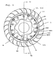
- the shows Fig. 1 a section perpendicular to the axis by an arrangement comprising a drum inner surface 11 and the cooperating with them brake shoes 14, wherein in this preferred embodiment, both the drum inner surface and the brake shoes with ceramic friction layers 111, 141 are executed.
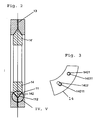
- the brake shoes 14 are formed at least on the peripheral part 142 with a wedge-shaped cross-section and engage in a wedge-shaped groove 112 in the drum inner surface ( Fig. 2 ).
- the brake shoes 14 have a crescent-shaped cross-section.
- the actuator 151 is here designed as a cam disk, which, in cooperation with the brake shoes 14 by rotating the cam disk 151, the brake shoes 14 outwardly in the direction of Drum inner surface 11 presses.
- the ceramic material of the friction layers 111, 141 is a carbon fiber reinforced silicon carbide ceramic ("C-SiC").
- C-SiC carbon fiber reinforced silicon carbide ceramic
- the closed design allows for the latter case, the use of inert gases, which eliminates the obstacle to the oxidative sensitivity of such systems.
- the drum brake 1 has at least one ceramic friction layer on one of the cooperating friction surfaces selected from the drum inner surface acting as a rotor 11 and cooperating with it as a stator brake shoes 14. Preferred embodiments will become apparent from the dependent claims.
- At least one outwardly open channel 13 is introduced, which has radially outwardly and preferably has a circular cross-section; it is particularly preferred to distribute such channels 13 over the entire circumference of the wedge-shaped groove.
- the Fig. 2 shows the section II-II according to Fig. 1 , wherein for the sake of clarity here only the brake shoes 14, 14 'and the brake drum 13 are shown.
- the drum inner surface 11 has the profile of a "V" directed outwards with the tip outwards from the center, into which the wedge-shaped cross-section of the off-axis peripheral region 142 of the brake shoe 14 engages.
- IV, V Various embodiments of the detailed area designated as "IV, V" are disclosed in US Pat FIGS. 4 and 5 shown, wherein a lumen for receiving dust and abrasion once according to Fig.
- FIG. 4 is formed by breaking the tip of the wedge-shaped portion 142 of the brake shoe 14 together with the V-shaped bottom of the profile of the wedge-shaped groove 112 of the brake drum, and in another embodiment according to Fig. 5 by deepening the bottom of the V-shaped profile of the brake drum 13 with an additional rectangular or rounded recess.
- the recess according to Fig. 5 and the broken edge according to Fig. 4 Of course, extend over the entire circumference of the drum inner surface or the length of the brake shoe.
- the rectangular recess as in Fig. 5 shown preferred a shape in which the edges at the bottom of the recess are rounded, as well as a rounded profile of the brake shoe 14 according to Fig. 4 , In the Fig.
- FIG. 3 an embodiment of the guide of a brake shoe 14 by a combination of a bolt 14011 with a circular hole 1401 on the one hand and a bolt 14011 in cooperation with a slot 1402 is shown.
- At least two brake shoes 14 are preferably provided. For manufacturing and actuation reasons, a maximum of 12 brake shoes are preferred in the case of the brake shoes shown in the drawings. Particularly favorable are odd numbers of brake shoes, with odd numbers, the noise is lower than in straight.
- the brake shoes 14 are guided by at least two guides 1401, 14011, 1402, 14011, wherein at least one of the guides is formed by a combination of a bolt 14011 and a slot 1402.
- both guides are executed with slots, so it is further preferred in the case of mechanical actuation by a cam to provide more than one, in particular at least two cams for each brake shoe, which can be ensured by the plurality of cams that the peripheral edge and the peripheral surfaces of the brake shoes are always concentric with the axis at the latest during frictional engagement with the drum inner surface.
- a guide through webs is possible and advantageous.
- drum brakes problem of the different effect of the two brake shoes (running and running brake shoes) in the design with two jaws can be avoided in the construction according to the invention, if both or in versions with more than two brake shoes, preferably all brake shoes as tapered jaws are arranged. In such an embodiment, however, these jaws then act as running brake shoes when reversing, with correspondingly reduced braking effect, but this can be tolerated for this mode of operation.
- the brake shoes are each moved back by one or more return springs 12, 152 in the rest position when the actuation actuator 151 returns to its original position or the pressure decreases, with the aid of the actuator 151 is provided.
- a common spring 12, 152 can be used, as in the Fig. 1 is shown, wherein the spring is stored at bases 121.
- brake shoes it is of course also possible within the scope of the invention to actuate the brake shoes directly and individually by electromechanical actuators, such as piezoelectric or electromagnetic actuators, or by pneumatic or hydraulic actuators. If the brake shoes are designed in the form of pins or flat cuboids according to claim 15, a guide through bushes is preferred. Due to the smaller space requirement in this case, especially in the case of brake pins, significantly larger numbers of these brake pins can be realized, for example, up to 100 brake pins.
- the channels can be machined in the radial direction by hard machining (drilling, in conductive ceramic materials such as silicon-bonded silicon carbide (SiSiC) and by radio erosion).
- hard machining drilling, in conductive ceramic materials such as silicon-bonded silicon carbide (SiSiC) and by radio erosion.
- Another possibility is to form the channels in the production of the drum inner lining of two half-slices, by processing the half-slices in the parting plane, in which case it is not limited to radial channels, but these, as in the Fig. 1 shown, can perform with involute contour.
- drum brakes according to the invention are preferable to the more sensitive disc brakes with ceramic brake rings, especially in harsh operating conditions.
Description
Die vorliegende Erfindung betrifft Trommelbremsen mit keramischen Reibflächen.The present invention relates to drum brakes with ceramic friction surfaces.
Derzeit werden in Fahrzeugen zwei unterschiedliche Systeme von Bremsen eingesetzt, Scheibenbremsen und Trommelbremsen. Während Scheibenbremsen für höhere Bremsleistungen bevorzugt eingesetzt werden wegen der besseren Wärmeabführung und der einfacheren Möglichkeit, die Bremsbeläge zu überprüfen und zu wechseln, werden Trommelbremsen für geringere Bremsleistungen wegen ihrer einfacheren Konstruktion und ihrer Unempfindlichkeit gegenüber Verschmutzung bevorzugt.Currently, vehicles use two different systems of brakes, disc brakes and drum brakes. While disc brakes are preferred for higher braking performance because of better heat dissipation and easier way to check and change the brake pads, drum brakes are preferred for lower braking performance because of their simpler design and insensitivity to contamination.
Trommelbremsen enthalten als wesentliche Komponenten ein zylinderförmiges umlaufendes Gehäuse (Trommel), an das beim Bremsen von innen (so verwendet in Fahrzeugen) oder von außen (verwendet beispielsweise bei Maschinenbremsen) drehbar oder schwenkbar gelagerte, ansonsten feststehende Bremsbacken gepreßt werden. Bei großer Wärmeentwicklung dehnt sich die Trommel aus, wobei bei innenliegenden Bremsbacken in üblicher Bauart diese an der Innenwand der Trommel nicht mehr vollständig anliegen und die Bremse daher an Wirkung verliert. Das Betätigen (Stellen) der Bremsbacken erfolgt üblicherweise durch Hydraulikzylinder im Inneren der Trommel oder über drehbare Exzenter von außen.Drum brakes contain as essential components a cylindrical rotating housing (drum) to which when braking from the inside (used in vehicles) or from the outside (used for example in engine brakes) rotatably or pivotally mounted, otherwise fixed brake shoes are pressed. At high heat development, the drum expands, with inner brake shoes in the usual design, these no longer completely rest against the inner wall of the drum and therefore the brake loses its effect. The actuation (positioning) of the brake shoes is usually carried out by hydraulic cylinders inside the drum or via rotatable eccentric from the outside.
Das Dokument
Die robustere Ausführungsform läßt Trommelbremsen attraktiv erscheinen, wenn es gelingt, die immanenten Nachteile gegenüber den Scheibenbremsen wie insbesondere die geringere Bremsleistung zu überwinden.The more robust embodiment makes drum brakes appear attractive, if it succeeds to overcome the immanent disadvantages compared to the disc brakes, in particular the lower braking power.
Es wurde nun gefunden, daß die Verwendung von keramischen Reibmaterialien zu einer erheblichen Verbesserung der Bremsleistung führt, ohne daß die bisher bei Trommelbremsen als gegeben erachteten Nachteile der schlechteren Wärmeabführung für die Eignung prohibitiv wären.It has now been found that the use of ceramic friction materials results in a significant improvement in braking performance without the disadvantages of poorer heat dissipation previously believed in drum brakes being prohibitive for suitability.
Die Erfindung betrifft daher eine Trommelbremse mit den Merkmalen des Anspruchs 1.The invention therefore relates to a drum brake with the features of
Die Erfindung wird durch die angelegten Zeichnungen erläutert. Dabei zeigen die
- Fig. 1
- eine Draufsicht auf einen Schnitt senkrecht zur Achse durch eine
Trommelbremse 1 mit mindestens einer keramischen Reibschicht an einer der zusammenwirkenden Reibflächen, nämlich der als Rotorwirkenden Trommelinnenfläche 11 und/oder den mit ihr als Stator zusammenwirkenden Bremsbacken 14, - Fig. 2
- einen Schnitt längs der Linie II-II durch eine
Trommelbremse 1 in einer die in der Zeichnung nicht dargestellten Achse enthaltenden Ebene, wobei zur Verbesserung der Übersichtlichkeit der Aktuator ebenfalls nicht dargestellt ist, - Fig. 3
- eine Draufsicht in Richtung der Achse auf eine
Bremsbacke 14 mit einer Lagerung durch eine Kombination von Bolzen und Rundloch und eine Kombination von Bolzen und Langloch, - Fig.4
- ein Detail IV eines Schnitts gemäß
Fig. 2 , wobei in dieser Ausführung die Spitze derBremsbacke 14 gebrochen ist, wodurch an der Berührungsstelle der Spitze derBremsbacke 14 und derkeilförmigen Nut 112 der Bremstrommel ein Lumen entsteht, und - Fig. 5
- ein Detail V eines Schnitts gemäß
Fig. 2 , wobei in dieser Ausführung der achsferne Grund derkeilförmigen Nut 112 der Bremstrommel eine zusätzliche Ausnehmung mit rechteckförmigem oder verrundetem Querschnitt aufweist, wodurch an der Berührungsstelle der Spitze derBremsbacke 14 und derkeilförmigen Nut 112 der Bremstrommel ein Lumen entsteht.
- Fig. 1
- a top view of a section perpendicular to the axis by a
drum brake 1 with at least one ceramic friction layer on one of the cooperating friction surfaces, namely acting as a rotor druminner surface 11 and / or cooperating with her as astator brake shoes 14, - Fig. 2
- 3 shows a section along the line II-II through a
drum brake 1 in a plane which does not show the axis shown in the drawing, the actuator also not being shown for the sake of clarity; - Fig. 3
- a plan view in the direction of the axis on a
brake shoe 14 with a bearing by a combination of bolt and round hole and a combination of bolt and slot, - Figure 4
- a detail IV of a section according to
Fig. 2 , wherein in this embodiment, the tip of thebrake shoe 14 is broken, whereby at the point of contact of the tip of thebrake shoe 14 and the wedge-shaped groove 112 of the brake drum, a lumen is formed, and - Fig. 5
- a detail V of a section according to
Fig. 2 , In this embodiment, the off-axis base of the wedge-shaped groove 112 of the brake drum has an additional recess with a rectangular or rounded cross-section, whereby at the point of contact of the tip of thebrake shoe 14 and the wedge-shaped groove 112 of the brake drum, a lumen is formed.
Im einzelnen zeigt die
Die Trommelbremse 1 gemäß der Erfindung weist mindestens eine keramische Reibschicht auf an einer der zusammenwirkenden Reibflächen ausgewählt aus der als Rotor wirkenden Trommelinnenfläche 11 und den mit ihr als Stator zusammenwirkenden Bremsbacken 14. Bevorzugte Ausführungsformen ergeben sich aus den Unteransprüchen.The
In einer bevorzugten Ausführungsform ist in der Mitte der keilförmigen Nut 112 mindestens ein nach außen offener Kanal 13 eingebracht, der radial nach außen weist und bevorzugt einen kreisförmigen Querschnitt aufweist; es ist besonders bevorzugt, derartige Kanäle 13 über den gesamten Umfang der keilförmigen Nut zu verteilen.In a preferred embodiment, in the middle of the wedge-
Die
Es werden bevorzugt mindestens zwei Bremsbacken 14 vorgesehen. Aus fertigungs- und betätigungstechnischen Gründen werden im Fall der in den Zeichnungen dargestellten Bremsbacken maximal 12 Bremsbacken bevorzugt. Besonders günstig sind ungerade Anzahlen von Bremsbacken, wobei bei ungeraden Anzahlen die Geräuschentwicklung niedriger ist als bei geraden. Die Bremsbacken 14 werden durch jeweils mindestens zwei Führungen 1401, 14011, 1402, 14011 geführt, wobei mindestens eine der Führungen durch eine Kombination von einem Bolzen 14011 und einem Langloch 1402 gebildet wird. Werden beide Führungen mit Langlöchern ausgeführt, so ist es weiter im Fall der mechanischen Betätigung durch eine Nockenscheibe bevorzugt, mehr als eine, insbesondere mindestens zwei Nocken für je eine Bremsbacke vorzusehen, wobei durch die Vielzahl an Nocken sichergestellt werden kann, daß die umfangsseitige Kante und die umfangsseitigen Flächen der Bremsbacken spätestens beim reibenden Eingriff mit der Trommelinnenfläche stets konzentrisch zur Achse stehen. Anstelle der in den Zeichnungen dargestellten Führung ist auch eine Führung durch Stege möglich und vorteilhaft.At least two
Das für Trommelbremsen charakteristische Problem der unterschiedlichen Wirkung der beiden Bremsbacken (auflaufender und ablaufender Bremsbacken) in der Ausführung mit zwei Backen läßt sich in der Bauweise gemäß der Erfindung vermeiden, wenn beide oder in Ausführungen mit mehr als zwei Bremsbacken, bevorzugt alle Bremsbacken als auflaufende Backen angeordnet sind. In einer solchen Ausführung wirken allerdings beim Rückwärtsfahren dann diese Backen als ablaufende Bremsbacken, mit entsprechend verminderter Bremswirkung, was aber für diese Betriebsweise toleriert werden kann.The characteristic of drum brakes problem of the different effect of the two brake shoes (running and running brake shoes) in the design with two jaws can be avoided in the construction according to the invention, if both or in versions with more than two brake shoes, preferably all brake shoes as tapered jaws are arranged. In such an embodiment, however, these jaws then act as running brake shoes when reversing, with correspondingly reduced braking effect, but this can be tolerated for this mode of operation.
Die Bremsbacken werden jeweils durch eine oder mehrere Rückholfedern 12, 152 in die Ruhestellung zurückbewegt, wenn der sie betätigende Aktuator 151 in seine Ausgangslage zurückkehrt oder der Druck nachläßt, mit dessen Hilfe der Aktuator 151 gestellt wird. Vorteilhafterweise kann auch eine gemeinsame Feder 12, 152 verwendet werden, so wie dies in der
Es ist im Rahmen der Erfindung selbstverständlich auch möglich, die Bremsbacken durch elektromechanische Aktuatoren, wie piezoelektrische oder elektromagnetische Aktuatoren, oder durch pneumatische oder hydraulische Aktuatoren direkt und einzeln zu betätigen. Werden die Bremsbacken in Form von Stiften oder flachen Quadern gemäß Anspruch 15 ausgeführt, so ist eine Führung durch Buchsen bevorzugt. Durch den geringeren Raumbedarf in diesem Fall, insbesondere im Fall von Bremsstiften, lassen sich erheblich größere Anzahlen dieser Bremsstifte realisieren, beispielsweise bis zu 100 Bremsstiften.It is of course also possible within the scope of the invention to actuate the brake shoes directly and individually by electromechanical actuators, such as piezoelectric or electromagnetic actuators, or by pneumatic or hydraulic actuators. If the brake shoes are designed in the form of pins or flat cuboids according to claim 15, a guide through bushes is preferred. Due to the smaller space requirement in this case, especially in the case of brake pins, significantly larger numbers of these brake pins can be realized, for example, up to 100 brake pins.
Die Kanäle können in radialer Richtung durch Hartbearbeitung (Bohren, in leitfähigen Keramikwerkstoffen wie mit Silicium gebundenem Siliciumcarbid (SiSiC) auch durch Funkerosion) eingearbeitet werden. Eine andere Möglichkeit ist bei der Fertigung des Trommelinnenbelags aus zwei Halbscheiben, durch Bearbeitung der Halbscheiben in der Trennebene die Kanäle zu formen, wobei man in diesem Fall nicht auf radiale Kanäle beschränkt ist, sondern diese auch, wie in der
Bei Betriebsversuchen mit einer Trommelbremse gemäß der Ausführungsform von
Es hat sich bei diesen Betriebsversuchen weiter in überraschender Weise ergeben, daß bei Betrieb einer Trommelbremse gemäß der vorliegenden Erfindung, wobei mindestens eine der zusammenwirkenden Reibflächen aus einem keramischen Werkstoff ausgeführt ist, keine störende Geräuschentwicklung auftrat, im Gegensatz zu Scheibenbremsen mit keramischen Reibpaarungen.It has also been surprisingly found in these operating experiments that when operating a drum brake according to the present invention, wherein at least one of the cooperating friction surfaces is made of a ceramic material, no disturbing noise occurred, in contrast to disc brakes with ceramic friction pairings.
- 11
- Trommelbremsedrum brake
- 1111
- TrommelinnenflächeDrum inner surface
- 111111
- keramische Reibschichtceramic friction layer
- 112112
- keilförmige Nut in der Trommelinnenflächewedge-shaped groove in the drum inner surface
- 12, 15212, 152
- Rückholfederreturn spring
- 121121
- Befestigungspunkt für RückholfederAttachment point for return spring
- 1313
- Kanalchannel
- 14, 14'14, 14 '
- Bremsbackenbrake shoes
- 14011401
- Führungslochhole
- 1401114011
- Bolzenbolt
- 14021402
- Führungs-LanglochGuide slot
- 141141
- keramische Reibschichtceramic friction layer
- 142142
-
keilförmiger Bereich der Bremsbacke 14wedge-shaped region of the
brake shoe 14 - 151151
- Aktuator, NockenscheibeActuator, cam disc
- 1616
- Führungguide
Claims (14)
- Drum brake (1) having at least one friction layer on one of the interacting friction surfaces selected from the drum inner surface (11), which acts as a rotor, and the brake shoes (14) which interact therewith as a stator, the brake shoes (14) being formed, at least on the peripheral part (142), with a wedge-shaped cross section and engaging into a wedge-shaped groove (112) in the drum inner surface, and a lumen for receiving dust and abraded material being formed by breaking the tip of the wedge-shaped region (142) of the brake shoe (14) together with the V-shaped base of the profile of the wedge-shaped groove (112) of the brake drum, or being formed by deepening the base of the V-shaped profile of the brake drum (13) with an additional rectangular or rounded recess, characterized in that the friction layer is a ceramic friction layer and at least two outwardly open ducts (13) are formed in the centre of the wedge-shaped groove (112).
- Drum brake (1) according to Claim 1, characterized in that both the drum inner surface (11) and also the brake shoes (14) which interact therewith have ceramic friction layers (111, 141).
- Drum brake (1) according to Claim 1, characterized in that at least two brake shoes (14, 14') are provided which are placed in engagement with the drum inner surface, and released again, by means of an activation device comprising an actuator (151) and a restoring device (12, 152).
- Drum brake (1) according to Claim 1, characterized in that the ceramic friction layer (111, 141) is a carbon-fibre-reinforced silicon carbide ceramic.
- Drum brake (1) according to Claim 3, characterized in that the actuator (151) presses mechanically on the brake shoes (14) outwards in the direction of the drum inner surface (11).
- Drum brake (1) according to Claim 3, characterized in that the actuator (151) is activated by an electromechanical control element selected from a piezoelectric and an electromagnetic control element.
- Drum brake (1) according to Claim 3, characterized in that the actuator (151) is activated by a mechanical control element selected from a pneumatic and a hydraulic control element.
- Drum brake (1) according to Claim 3, characterized in that the actuator is designed as a cam disc (151) having at least one cam per brake shoe, the brake shoes (14) being pressed in the direction of the drum inner surface (11) by means of a rotation of the cam disc (151).
- Drum brake (1) according to Claim 8, characterized in that the brake shoes (14) have a sickle-shaped cross section.
- Drum brake (1) according to Claim 1, characterized in that the outwardly open ducts (13) formed in the centre of the wedge-shaped groove (112) are distributed rotationally symmetrically over the entire circumference.
- Drum brake (1) according to Claim 1, characterized in that an uneven number of brake shoes (14) are provided.
- Drum brake (1) according to Claim 8, characterized in that the brake shoes (14) are guided in the radial direction by in each case at least two guides (1401, 14011, 1402, 14011), at least one of the guides being formed by a combination of a pin (14011) and a slot (1402).
- Drum brake (1) according to Claim 3, characterized in that the brake shoes are guided by webs or bushes.
- Drum brake according to Claim 13, characterized in that the brake shoes are designed in the form of pins which are rounded at the engagement surface with the drum inner surface or as or flat cuboids, and are guided in bushes.
Applications Claiming Priority (1)
| Application Number | Priority Date | Filing Date | Title |
|---|---|---|---|
| DE102006030301A DE102006030301A1 (en) | 2006-06-30 | 2006-06-30 | Drum brake with ceramic friction surfaces |
Publications (3)
| Publication Number | Publication Date |
|---|---|
| EP1873418A2 EP1873418A2 (en) | 2008-01-02 |
| EP1873418A3 EP1873418A3 (en) | 2009-11-11 |
| EP1873418B1 true EP1873418B1 (en) | 2011-09-14 |
Family
ID=38704717
Family Applications (1)
| Application Number | Title | Priority Date | Filing Date |
|---|---|---|---|
| EP07007064A Expired - Fee Related EP1873418B1 (en) | 2006-06-30 | 2007-04-04 | Drum brake with ceramic friction surfaces |
Country Status (3)
| Country | Link |
|---|---|
| US (1) | US20080000736A1 (en) |
| EP (1) | EP1873418B1 (en) |
| DE (1) | DE102006030301A1 (en) |
Families Citing this family (10)
| Publication number | Priority date | Publication date | Assignee | Title |
|---|---|---|---|---|
| DE102010003250B4 (en) * | 2010-03-25 | 2012-06-14 | Saf-Holland Gmbh | Actuation system for a drum brake |
| KR101607335B1 (en) * | 2010-04-14 | 2016-03-29 | 현대모비스 주식회사 | Friction device of drum brake |
| CN102338096B (en) * | 2010-07-28 | 2015-09-09 | 温州市康而达实业有限公司 | Vertical self-sucking pump |
| US9475342B2 (en) * | 2012-01-20 | 2016-10-25 | Chengdu Youyang Electromechanical Product Design Co., Ltd. | Wheel hub, wheel hub motor wheel, and electric vehicle |
| CN104373488B (en) * | 2014-12-09 | 2016-08-17 | 叶雪峰 | Elastomeric brakes |
| DE102018004897A1 (en) | 2018-06-16 | 2019-12-19 | Psa Automobiles Sa | Drum brake and motor vehicle |
| CN112377541B (en) * | 2020-12-21 | 2022-05-06 | 北京安声科技有限公司 | Noise-reducing brake beam with remarkable noise-reducing effect for vehicle |
| DE102021115785B3 (en) * | 2021-06-18 | 2022-09-15 | Knorr-Bremse Systeme für Nutzfahrzeuge GmbH | drum brake |
| DE102022104343A1 (en) | 2022-02-23 | 2023-08-24 | Zf Cv Systems Global Gmbh | Vehicle drum brake, in particular for commercial vehicles |
| DE102022210296A1 (en) | 2022-09-28 | 2024-03-28 | Psa Automobiles Sa | Drum brake for a vehicle |
Family Cites Families (14)
| Publication number | Priority date | Publication date | Assignee | Title |
|---|---|---|---|---|
| US1909034A (en) * | 1930-07-22 | 1933-05-16 | Joseph H Durst | Brake |
| US1908228A (en) * | 1931-04-30 | 1933-05-09 | Dotson Leroy | Automotive brake |
| US2167297A (en) * | 1935-09-07 | 1939-07-25 | Fitts George Mckinley | Brake |
| US2260340A (en) * | 1940-01-18 | 1941-10-28 | Detroit Hydrostatic Brake Corp | Hydrostatic brake |
| US2582755A (en) * | 1947-05-08 | 1952-01-15 | Kenny Richard Joseph | Internal expanding brake |
| DE1193745B (en) * | 1958-09-24 | 1965-05-26 | Fijn Mechanische Ind Becker S | Inner shoe brake |
| DE3515512A1 (en) * | 1985-04-30 | 1986-10-30 | Bayerische Motoren Werke AG, 8000 München | FRICTION RING, ESPECIALLY FOR DISC OR DRUM BRAKES |
| DE3640212A1 (en) * | 1986-11-25 | 1988-06-01 | Didier Werke Ag | Brake disc or drum |
| US5782324A (en) * | 1995-12-27 | 1998-07-21 | Dayton Walther Corporation | Composite brake drum and method for producing same |
| US6196359B1 (en) * | 1998-04-10 | 2001-03-06 | Hayes Lemmerz International, Inc. | Vehicle braking system and braking method using a plurality of two-state actuators |
| US6458466B1 (en) * | 1998-04-24 | 2002-10-01 | Dow Global Technologies Inc. | Brake or clutch components having a ceramic-metal composite friction material |
| JP3441392B2 (en) * | 1999-02-12 | 2003-09-02 | 本田技研工業株式会社 | Method of manufacturing rotary friction member |
| JP3715125B2 (en) * | 1999-02-12 | 2005-11-09 | 本田技研工業株式会社 | Brake drum |
| US20060278484A1 (en) * | 2005-06-10 | 2006-12-14 | Slavo Antolovic | Radially expanding braking device |
-
2006
- 2006-06-30 DE DE102006030301A patent/DE102006030301A1/en not_active Withdrawn
-
2007
- 2007-04-04 EP EP07007064A patent/EP1873418B1/en not_active Expired - Fee Related
- 2007-06-26 US US11/819,233 patent/US20080000736A1/en not_active Abandoned
Also Published As
| Publication number | Publication date |
|---|---|
| EP1873418A3 (en) | 2009-11-11 |
| US20080000736A1 (en) | 2008-01-03 |
| DE102006030301A1 (en) | 2008-01-10 |
| EP1873418A2 (en) | 2008-01-02 |
Similar Documents
| Publication | Publication Date | Title |
|---|---|---|
| EP1873418B1 (en) | Drum brake with ceramic friction surfaces | |
| DE60116094T2 (en) | HARD SADDLE PART LINING DISC BRAKE | |
| DE69824731T2 (en) | IMPROVEMENTS ON DISC BRAKES | |
| EP1832777B1 (en) | Disc brake | |
| DE60216212T2 (en) | Safety blocking device for an electromechanical device and brake of an aircraft equipped therewith | |
| EP0472495B1 (en) | Key and rotary cylinder for a safety lock | |
| DE60009238T2 (en) | Interchangeable brake disc set in three stages and procedures for assembly | |
| WO2019204844A1 (en) | Friction plate | |
| EP2138279A1 (en) | Electric hand tool device with braking mechanism | |
| WO2004099642A1 (en) | Lining for disc brakes | |
| EP1530686A1 (en) | Disc brake having at least two friction rings | |
| EP0822351B1 (en) | Brake system,in particular floating caliper-type disc brake,for a motor vehicle | |
| DE60021651T2 (en) | Interchangeable brake disc set in three stages and procedures for assembly | |
| EP1256287A2 (en) | Rotating cylinder for an epilator | |
| DE69909294T2 (en) | DISC BRAKE SYSTEM | |
| DE3027139C2 (en) | Disc brake | |
| EP2112395B1 (en) | Braking and/or clamping device for shafts | |
| DE10296458T5 (en) | Compact disc holder | |
| DE102019206736A1 (en) | Depending on the direction of rotation, assembled disc brake pad for a fixed caliper disc brake | |
| AT524801B1 (en) | Electromechanical spindle drive | |
| DE10125211A1 (en) | Disc brake unit for a vehicle wheel | |
| DE2629211C3 (en) | Self-energizing full disc brake, especially of the wet-running type | |
| DE2557439A1 (en) | VEHICLE DISC BRAKE | |
| DE19928747A1 (en) | Brake disc for a disc brake | |
| DE2726741C3 (en) | Brake disc |
Legal Events
| Date | Code | Title | Description |
|---|---|---|---|
| PUAI | Public reference made under article 153(3) epc to a published international application that has entered the european phase |
Free format text: ORIGINAL CODE: 0009012 |
|
| AK | Designated contracting states |
Kind code of ref document: A2 Designated state(s): AT BE BG CH CY CZ DE DK EE ES FI FR GB GR HU IE IS IT LI LT LU LV MC MT NL PL PT RO SE SI SK TR |
|
| AX | Request for extension of the european patent |
Extension state: AL BA HR MK YU |
|
| PUAL | Search report despatched |
Free format text: ORIGINAL CODE: 0009013 |
|
| AK | Designated contracting states |
Kind code of ref document: A3 Designated state(s): AT BE BG CH CY CZ DE DK EE ES FI FR GB GR HU IE IS IT LI LT LU LV MC MT NL PL PT RO SE SI SK TR |
|
| AX | Request for extension of the european patent |
Extension state: AL BA HR MK RS |
|
| 17P | Request for examination filed |
Effective date: 20100511 |
|
| 17Q | First examination report despatched |
Effective date: 20100610 |
|
| AKX | Designation fees paid |
Designated state(s): DE FR GB IT |
|
| GRAP | Despatch of communication of intention to grant a patent |
Free format text: ORIGINAL CODE: EPIDOSNIGR1 |
|
| GRAS | Grant fee paid |
Free format text: ORIGINAL CODE: EPIDOSNIGR3 |
|
| GRAA | (expected) grant |
Free format text: ORIGINAL CODE: 0009210 |
|
| AK | Designated contracting states |
Kind code of ref document: B1 Designated state(s): DE FR GB IT |
|
| REG | Reference to a national code |
Ref country code: DE Ref legal event code: R096 Ref document number: 502007008126 Country of ref document: DE Effective date: 20111208 |
|
| PLBE | No opposition filed within time limit |
Free format text: ORIGINAL CODE: 0009261 |
|
| STAA | Information on the status of an ep patent application or granted ep patent |
Free format text: STATUS: NO OPPOSITION FILED WITHIN TIME LIMIT |
|
| 26N | No opposition filed |
Effective date: 20120615 |
|
| REG | Reference to a national code |
Ref country code: DE Ref legal event code: R097 Ref document number: 502007008126 Country of ref document: DE Effective date: 20120615 |
|
| PGFP | Annual fee paid to national office [announced via postgrant information from national office to epo] |
Ref country code: GB Payment date: 20140422 Year of fee payment: 8 |
|
| PGFP | Annual fee paid to national office [announced via postgrant information from national office to epo] |
Ref country code: DE Payment date: 20140430 Year of fee payment: 8 Ref country code: FR Payment date: 20140424 Year of fee payment: 8 Ref country code: IT Payment date: 20140419 Year of fee payment: 8 |
|
| REG | Reference to a national code |
Ref country code: DE Ref legal event code: R119 Ref document number: 502007008126 Country of ref document: DE |
|
| GBPC | Gb: european patent ceased through non-payment of renewal fee |
Effective date: 20150404 |
|
| PG25 | Lapsed in a contracting state [announced via postgrant information from national office to epo] |
Ref country code: GB Free format text: LAPSE BECAUSE OF NON-PAYMENT OF DUE FEES Effective date: 20150404 Ref country code: IT Free format text: LAPSE BECAUSE OF NON-PAYMENT OF DUE FEES Effective date: 20150404 Ref country code: DE Free format text: LAPSE BECAUSE OF NON-PAYMENT OF DUE FEES Effective date: 20151103 |
|
| REG | Reference to a national code |
Ref country code: FR Ref legal event code: ST Effective date: 20151231 |
|
| PG25 | Lapsed in a contracting state [announced via postgrant information from national office to epo] |
Ref country code: FR Free format text: LAPSE BECAUSE OF NON-PAYMENT OF DUE FEES Effective date: 20150430 |