US1908228A - Automotive brake - Google Patents
Automotive brake Download PDFInfo
- Publication number
- US1908228A US1908228A US533885A US53388531A US1908228A US 1908228 A US1908228 A US 1908228A US 533885 A US533885 A US 533885A US 53388531 A US53388531 A US 53388531A US 1908228 A US1908228 A US 1908228A
- Authority
- US
- United States
- Prior art keywords
- brake
- cam
- shoes
- ring
- shoe
- Prior art date
- Legal status (The legal status is an assumption and is not a legal conclusion. Google has not performed a legal analysis and makes no representation as to the accuracy of the status listed.)
- Expired - Lifetime
Links
- 239000002184 metal Substances 0.000 description 2
- 241000239290 Araneae Species 0.000 description 1
- 230000032683 aging Effects 0.000 description 1
- 230000004048 modification Effects 0.000 description 1
- 238000012986 modification Methods 0.000 description 1
Images

Classifications
-
- F—MECHANICAL ENGINEERING; LIGHTING; HEATING; WEAPONS; BLASTING
- F16—ENGINEERING ELEMENTS AND UNITS; GENERAL MEASURES FOR PRODUCING AND MAINTAINING EFFECTIVE FUNCTIONING OF MACHINES OR INSTALLATIONS; THERMAL INSULATION IN GENERAL
- F16D—COUPLINGS FOR TRANSMITTING ROTATION; CLUTCHES; BRAKES
- F16D51/00—Brakes with outwardly-movable braking members co-operating with the inner surface of a drum or the like
- F16D51/16—Brakes with outwardly-movable braking members co-operating with the inner surface of a drum or the like shaped as brake-shoes pivoted on a fixed or nearly-fixed axis
- F16D51/32—Brakes with outwardly-movable braking members co-operating with the inner surface of a drum or the like shaped as brake-shoes pivoted on a fixed or nearly-fixed axis with three or more brake shoes
- F16D51/40—Brakes with outwardly-movable braking members co-operating with the inner surface of a drum or the like shaped as brake-shoes pivoted on a fixed or nearly-fixed axis with three or more brake shoes all extending in the same direction from their pivots
- F16D51/42—Brakes with outwardly-movable braking members co-operating with the inner surface of a drum or the like shaped as brake-shoes pivoted on a fixed or nearly-fixed axis with three or more brake shoes all extending in the same direction from their pivots mechanically actuated
Definitions
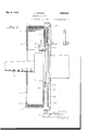
- igure 1 is a front elevation with the axle in section of a brake drum and my braking mechanism.
- Figure 2 is a section on the line 2-2 of Figre 1.
- 1 is an axle of a: vehicle carrying the brake drum 2 having a brake lining 3.
- This lin- 3o ing is engaged by a plurality of shoes which may be very cheaply made of ressed metal, if desired, comprising the vertical shoe body 4 and a shoe face 5.
- the shoe body is piv- I, oted atfitothe plate 7.
- a detachable cam plate 8 engaging with the, cam roller 9 which is mounted on a shaft 10 upon the ring disk or spider 11 which is rotatably mounted upon the axle 1.
- This ring 11 is provided with an arm v12 that is normally yieldingly held in its inoperative position by the helical spring 13,
- the brake shoe itself is restrained normally by the helical spring 16, against centrifugal force.
- This spring 16 is connected to the brake shoe at 17 and plate 7 at 18.
- the brake shoes themselves ma bekmade of cast or dead weig cuted. i
- the ring 11' is substantiallya floating 1 a clearance between it and 1 y the sup orting ub. This enables the wear 70. on the rake shoes to be compensated for ring, there bei by the movement of this ring; i I desire to comprehend wit in my invention such modifications as may be embraced within my claims and the scope of my in- "IQ- vention.
- cam actuating means mounted in floatin re ation centrally of the brake shoes and a jacent said cam faces and in en agement therewith, means for actuating sai cams to actuate said shoes, yielding means to restrain 90 the outward movement of said shoes until positively actuated by said cam means, and yielding means to restrain the inward movement until positively actuated by the 'cam means,
- a brake drum having a 'flange, a plurality of shoes en aging substantially the entire area of the ange means of pivotally mountressed metal so that t e cost or 05 t may be very;materially: re.-
- a brake drum In combination, a brake drum, a brake shoe pivoted thereto adjacent its rear end, a an operating cam on the interior of the brake shoe located centrally thereof and a floating 1 ring having a cam roller adapted to engage said cam-andactuate said brake shoe against the. brake drum progressively from ad acent thee-pivot end) towards theifree end of the brakeshoe;
- a brake drum In combination, a brake drum, a brake shoe pivoted thereto adjacent its rear end, an operating-mam on-the interior of the brake shoe located centrally thereof, and a floatingring having a cam roller adapted to engagewsaid cam. andv actuate said brake shoe against the brake drum progressively from adjacent the pivot and towards the free end of-the Eblilke shoe, said cam being arranged so thatits face diverges in a curved path in r 1 wardly from the curvature of the brake shoe engagin'gface and the brake drum from the pigot end of the brake shoe toward its free 611 l Intestimony whereof, I afiix my signa ture. I I a 35 I a LEROY DOTSON.
Landscapes
- Engineering & Computer Science (AREA)
- General Engineering & Computer Science (AREA)
- Mechanical Engineering (AREA)
- Braking Arrangements (AREA)
Description
L. DOTSO N AUTOMOT IVE BRAKE May 9, 1933,
2 Sheets-Sheet 1 Filed April 50, 1931 11v VENTOR A4 TTORNE VJ L. DOTSON AUTOMOTIVE BRAKE May 9, 1933.
2 Shets-Sheet 2 Filed April 30, 1931 A Q. L. M)
Patented May 9, 1933 UNITED I STATES minor person, or cor-fonds, if],
auroxonva s m? l Application nee Ami 30,1031: Serial at. mass] My invention relates to an automotive brake.
It is an object of my invention to provide operating mechanism, while at the same time providing uniform braking action,
an easily adjusted, and brake shoes engaging substantially all of the brakin surface.
Referring to the drawings, igure 1 is a front elevation with the axle in section of a brake drum and my braking mechanism. as Figure 2 is a section on the line 2-2 of Figre 1. I
ferring to the drawings in detail, 1 is an axle of a: vehicle carrying the brake drum 2 having a brake lining 3. This lin- 3o ing is engaged by a plurality of shoes which may be very cheaply made of ressed metal, if desired, comprising the vertical shoe body 4 and a shoe face 5. The shoe body is piv- I, oted atfitothe plate 7.
as Mounted on the inner side of the brake shoe body 4 is a detachable cam plate 8 engaging with the, cam roller 9 which is mounted on a shaft 10 upon the ring disk or spider 11 which is rotatably mounted upon the axle 1. I
This ring 11 is provided with an arm v12 that is normally yieldingly held in its inoperative position by the helical spring 13,
which is attached to it at 14 and to a stationary support such as the plate 7 at 15.
The brake shoe itself is restrained normally by the helical spring 16, against centrifugal force. This spring 16 is connected to the brake shoe at 17 and plate 7 at 18. I
The actuating means for the brakes, not
which. is carried by the wheel. f
It is a further object to provide a braking shown for: the purpose of clearnes, is 'conf-'- nected to the lever 12. By thevrotation of; the ring 11.,with t hecam rollers 9 against: Y the cam faces 8, thebrake shoes 14'have their brakin faces '5' moved outwardly against 86 the bra e lining?) to rotate the brakedrum It will. be noted. hat for'adjustmen "and repair, either-the rollers 9 orthe cam-plates Smay be replaced. Suchan operatiomis a (0.. y
simple one by detaching thescrewsand nuts I I indicated ,in the drawings. Anyone-without mechanical skill can perform this operation,
The brake shoes themselves ma bekmade of cast or dead weig duced. i
The ring 11' is substantiallya floating 1 a clearance between it and 1 y the sup orting ub. This enables the wear 70. on the rake shoes to be compensated for ring, there bei by the movement of this ring; i I desire to comprehend wit in my invention such modifications as may be embraced within my claims and the scope of my in- "IQ- vention.
Having thus full described my invention,
what I claim as new and desire to secure by Letters Patent, is:
1. In a braking mechanism, a brake "drum, so,
a plurality of inwardly disposed brake shoes, means for pivotal y shoes at one end, cam faces having rtions of greatest depth near the free en ofsaid shoes and located near the center thereof cam actuating means mounted in floatin re ation centrally of the brake shoes and a jacent said cam faces and in en agement therewith, means for actuating sai cams to actuate said shoes, yielding means to restrain 90 the outward movement of said shoes until positively actuated by said cam means, and yielding means to restrain the inward movement until positively actuated by the 'cam means,
2. In an automotive braking mechanism, a brake drum having a 'flange, a plurality of shoes en aging substantially the entire area of the ange means of pivotally mountressed metal so that t e cost or 05 t may be very;materially: re.-
s Said-w 'ng said shoes ad acent the ends thereof and I within said liner, a floating ring pivotally mounted upon the axle, cam rollers on said ring adapted to engage cam faces on the interior of said brake shoes substantially centrally of the shoes and movable in the 5 operation of applying the shoes; toward the free ends thereof wherebysaid brake shoes are simultaneously ogerated equally, said cam faces comprising etachable cam plates.
3. In combination, a brake drum, a brake shoe pivoted thereto adjacent its rear end, a an operating cam on the interior of the brake shoe located centrally thereof and a floating 1 ring having a cam roller adapted to engage said cam-andactuate said brake shoe against the. brake drum progressively from ad acent thee-pivot end) towards theifree end of the brakeshoe;
a a 1,, n :4.- In combination, a brake drum, a brake shoe pivoted thereto adjacent its rear end, an operating-mam on-the interior of the brake shoe located centrally thereof, and a floatingring having a cam roller adapted to engagewsaid cam. andv actuate said brake shoe against the brake drum progressively from adjacent the pivot and towards the free end of-the Eblilke shoe, said cam being arranged so thatits face diverges in a curved path in r 1 wardly from the curvature of the brake shoe engagin'gface and the brake drum from the pigot end of the brake shoe toward its free 611 l Intestimony whereof, I afiix my signa ture. I I a 35 I a LEROY DOTSON.
Priority Applications (1)
| Application Number | Priority Date | Filing Date | Title |
|---|---|---|---|
| US533885A US1908228A (en) | 1931-04-30 | 1931-04-30 | Automotive brake |
Applications Claiming Priority (1)
| Application Number | Priority Date | Filing Date | Title |
|---|---|---|---|
| US533885A US1908228A (en) | 1931-04-30 | 1931-04-30 | Automotive brake |
Publications (1)
| Publication Number | Publication Date |
|---|---|
| US1908228A true US1908228A (en) | 1933-05-09 |
Family
ID=24127832
Family Applications (1)
| Application Number | Title | Priority Date | Filing Date |
|---|---|---|---|
| US533885A Expired - Lifetime US1908228A (en) | 1931-04-30 | 1931-04-30 | Automotive brake |
Country Status (1)
| Country | Link |
|---|---|
| US (1) | US1908228A (en) |
Cited By (8)
| Publication number | Priority date | Publication date | Assignee | Title |
|---|---|---|---|---|
| US2606036A (en) * | 1945-11-01 | 1952-08-05 | Six Wheels Inc | Mounting for wheel brake operating mechanism |
| US6290028B1 (en) * | 2000-05-09 | 2001-09-18 | Liu Jen-Chih | Bike brake |
| EP1157920A1 (en) * | 2000-05-23 | 2001-11-28 | Jen-Chih Liu | Bicycle brake |
| EP1293423A1 (en) * | 2001-09-14 | 2003-03-19 | Jen-Chih Liu | Bicycle brake |
| US20060278484A1 (en) * | 2005-06-10 | 2006-12-14 | Slavo Antolovic | Radially expanding braking device |
| US20080000736A1 (en) * | 2006-06-30 | 2008-01-03 | Audi Ag | Drum brake with ceramic friction surfaces |
| US20080296011A1 (en) * | 2005-12-14 | 2008-12-04 | Oil Lift Technology Inc. | Cam-Actuated Centrifugal Brake for Preventing Backspin |
| US20150152927A1 (en) * | 2012-06-07 | 2015-06-04 | Ts Tech Co., Ltd. | Brake device |
-
1931
- 1931-04-30 US US533885A patent/US1908228A/en not_active Expired - Lifetime
Cited By (10)
| Publication number | Priority date | Publication date | Assignee | Title |
|---|---|---|---|---|
| US2606036A (en) * | 1945-11-01 | 1952-08-05 | Six Wheels Inc | Mounting for wheel brake operating mechanism |
| US6290028B1 (en) * | 2000-05-09 | 2001-09-18 | Liu Jen-Chih | Bike brake |
| EP1157920A1 (en) * | 2000-05-23 | 2001-11-28 | Jen-Chih Liu | Bicycle brake |
| EP1293423A1 (en) * | 2001-09-14 | 2003-03-19 | Jen-Chih Liu | Bicycle brake |
| US20060278484A1 (en) * | 2005-06-10 | 2006-12-14 | Slavo Antolovic | Radially expanding braking device |
| US20080296011A1 (en) * | 2005-12-14 | 2008-12-04 | Oil Lift Technology Inc. | Cam-Actuated Centrifugal Brake for Preventing Backspin |
| US9027717B2 (en) * | 2005-12-14 | 2015-05-12 | Oil Lift Technology Inc. | Cam-actuated centrifugal brake for preventing backspin |
| US20080000736A1 (en) * | 2006-06-30 | 2008-01-03 | Audi Ag | Drum brake with ceramic friction surfaces |
| US20150152927A1 (en) * | 2012-06-07 | 2015-06-04 | Ts Tech Co., Ltd. | Brake device |
| US9599174B2 (en) * | 2012-06-07 | 2017-03-21 | Ts Tech Co., Ltd. | Brake device |
Similar Documents
| Publication | Publication Date | Title |
|---|---|---|
| US1908228A (en) | Automotive brake | |
| US2118188A (en) | Brake | |
| US2406201A (en) | Brake mechanism | |
| US2278144A (en) | Disk brake | |
| US2757761A (en) | Self-energizing disc type wheel brake | |
| US1915857A (en) | Three-piece brake shoe | |
| US3186516A (en) | Brake installation for motor vehicles | |
| US2130857A (en) | Brake | |
| US1984348A (en) | Brake | |
| US2241479A (en) | Brake mechanism | |
| US2016875A (en) | Vehicle brake | |
| US3285370A (en) | Disk brakes | |
| US2365726A (en) | Electromagnetically actuated brake | |
| US1673713A (en) | Automobile brake | |
| US1482816A (en) | Brake mechanism for motor vehicles | |
| US2055330A (en) | Vehicle brake | |
| US2196137A (en) | Automatic brake adjuster | |
| US1635571A (en) | Brake | |
| US1896452A (en) | Brake mechanism | |
| US2259835A (en) | Compensating means for brake drum distortion | |
| US2020578A (en) | Brake | |
| US2059913A (en) | Vehicle brake | |
| US1372166A (en) | Vehicle-brake | |
| GB1339664A (en) | Vehicle brakes | |
| US1750611A (en) | Internal brake |