EP1873065A1 - Apparatus for separating interconnected cushions, and assembly of such an apparatus and an apparatus for manufacturing interconnected cushions - Google Patents
Apparatus for separating interconnected cushions, and assembly of such an apparatus and an apparatus for manufacturing interconnected cushions Download PDFInfo
- Publication number
- EP1873065A1 EP1873065A1 EP20070111483 EP07111483A EP1873065A1 EP 1873065 A1 EP1873065 A1 EP 1873065A1 EP 20070111483 EP20070111483 EP 20070111483 EP 07111483 A EP07111483 A EP 07111483A EP 1873065 A1 EP1873065 A1 EP 1873065A1
- Authority
- EP
- European Patent Office
- Prior art keywords
- cushions
- separating apparatus
- circulating
- conveying means
- separating
- Prior art date
- Legal status (The legal status is an assumption and is not a legal conclusion. Google has not performed a legal analysis and makes no representation as to the accuracy of the status listed.)
- Granted
Links
Images


Classifications
-
- B—PERFORMING OPERATIONS; TRANSPORTING
- B65—CONVEYING; PACKING; STORING; HANDLING THIN OR FILAMENTARY MATERIAL
- B65B—MACHINES, APPARATUS OR DEVICES FOR, OR METHODS OF, PACKAGING ARTICLES OR MATERIALS; UNPACKING
- B65B61/00—Auxiliary devices, not otherwise provided for, for operating on sheets, blanks, webs, binding material, containers or packages
- B65B61/04—Auxiliary devices, not otherwise provided for, for operating on sheets, blanks, webs, binding material, containers or packages for severing webs, or for separating joined packages
- B65B61/12—Auxiliary devices, not otherwise provided for, for operating on sheets, blanks, webs, binding material, containers or packages for severing webs, or for separating joined packages by tearing along perforations or lines of weakness
-
- B—PERFORMING OPERATIONS; TRANSPORTING
- B31—MAKING ARTICLES OF PAPER, CARDBOARD OR MATERIAL WORKED IN A MANNER ANALOGOUS TO PAPER; WORKING PAPER, CARDBOARD OR MATERIAL WORKED IN A MANNER ANALOGOUS TO PAPER
- B31D—MAKING ARTICLES OF PAPER, CARDBOARD OR MATERIAL WORKED IN A MANNER ANALOGOUS TO PAPER, NOT PROVIDED FOR IN SUBCLASSES B31B OR B31C
- B31D5/00—Multiple-step processes for making three-dimensional articles ; Making three-dimensional articles
- B31D5/0039—Multiple-step processes for making three-dimensional articles ; Making three-dimensional articles for making dunnage or cushion pads
- B31D5/0073—Multiple-step processes for making three-dimensional articles ; Making three-dimensional articles for making dunnage or cushion pads including pillow forming
-
- B—PERFORMING OPERATIONS; TRANSPORTING
- B31—MAKING ARTICLES OF PAPER, CARDBOARD OR MATERIAL WORKED IN A MANNER ANALOGOUS TO PAPER; WORKING PAPER, CARDBOARD OR MATERIAL WORKED IN A MANNER ANALOGOUS TO PAPER
- B31D—MAKING ARTICLES OF PAPER, CARDBOARD OR MATERIAL WORKED IN A MANNER ANALOGOUS TO PAPER, NOT PROVIDED FOR IN SUBCLASSES B31B OR B31C
- B31D2205/00—Multiple-step processes for making three-dimensional articles
- B31D2205/0005—Multiple-step processes for making three-dimensional articles for making dunnage or cushion pads
- B31D2205/0011—Multiple-step processes for making three-dimensional articles for making dunnage or cushion pads including particular additional operations
- B31D2205/0052—Perforating; Forming lines of weakness
-
- B—PERFORMING OPERATIONS; TRANSPORTING
- B31—MAKING ARTICLES OF PAPER, CARDBOARD OR MATERIAL WORKED IN A MANNER ANALOGOUS TO PAPER; WORKING PAPER, CARDBOARD OR MATERIAL WORKED IN A MANNER ANALOGOUS TO PAPER
- B31D—MAKING ARTICLES OF PAPER, CARDBOARD OR MATERIAL WORKED IN A MANNER ANALOGOUS TO PAPER, NOT PROVIDED FOR IN SUBCLASSES B31B OR B31C
- B31D2205/00—Multiple-step processes for making three-dimensional articles
- B31D2205/0005—Multiple-step processes for making three-dimensional articles for making dunnage or cushion pads
- B31D2205/0011—Multiple-step processes for making three-dimensional articles for making dunnage or cushion pads including particular additional operations
- B31D2205/0058—Cutting; Individualising the final products
-
- Y—GENERAL TAGGING OF NEW TECHNOLOGICAL DEVELOPMENTS; GENERAL TAGGING OF CROSS-SECTIONAL TECHNOLOGIES SPANNING OVER SEVERAL SECTIONS OF THE IPC; TECHNICAL SUBJECTS COVERED BY FORMER USPC CROSS-REFERENCE ART COLLECTIONS [XRACs] AND DIGESTS
- Y10—TECHNICAL SUBJECTS COVERED BY FORMER USPC
- Y10T—TECHNICAL SUBJECTS COVERED BY FORMER US CLASSIFICATION
- Y10T225/00—Severing by tearing or breaking
- Y10T225/30—Breaking or tearing apparatus
- Y10T225/336—Conveyor diverter for moving work
-
- Y—GENERAL TAGGING OF NEW TECHNOLOGICAL DEVELOPMENTS; GENERAL TAGGING OF CROSS-SECTIONAL TECHNOLOGIES SPANNING OVER SEVERAL SECTIONS OF THE IPC; TECHNICAL SUBJECTS COVERED BY FORMER USPC CROSS-REFERENCE ART COLLECTIONS [XRACs] AND DIGESTS
- Y10—TECHNICAL SUBJECTS COVERED BY FORMER USPC
- Y10T—TECHNICAL SUBJECTS COVERED BY FORMER US CLASSIFICATION
- Y10T225/00—Severing by tearing or breaking
- Y10T225/30—Breaking or tearing apparatus
- Y10T225/35—Work-parting pullers [bursters]
Definitions
- the invention relates to an apparatus for separating interconnected cushions, by breaking weakening lines provided between these cushions.
- Such cushions may, for instance, be manufactured from tubular film material which is divided into chambers by means of cross sealing seams. These chambers are filled with air or another gas or gas mixture and then closed, for instance by sealing. After this, the cushions are separated from one another by the piece or by string, by breaking weakening lines provided in the film material. The separated cushions may, for instance, be used as filling and/or protective material in packagings.
- a drawback of this known apparatus is that the clamping elements need to carry out a relatively complicated movement, in which they are first displaced in the direction of the film material, substantially at right angles to a conveying direction of this film material, are then moved apart, parallel to this conveying direction, and are finally withdrawn again, substantially at right angles to the conveying direction.
- This requires complex drive means taking up relatively much space.
- an apparatus according to the invention is characterized by use of a circulating element having a circulating speed or peripheral speed which is considerably higher than a conveying speed of the interconnected cushions.
- a 'circulating element' is understood to mean an element or element part which is arranged for carrying out a revolution or a circulating movement, such as for instance a belt guided around a number of drive and/or guide rollers or a wheel which can rotate about an axis.
- the respective cushion By temporarily bringing such a circulating element into engagement with one of the cushions, the respective cushion will be carried along at a carrying speed which is much higher than the conveying speed of the adjacent cushions. As a result, the weakening line between this cushion and the adjacent cushions will be subject to a tensile force, which causes the line to break.
- Temporarily bringing the circulating element into engagement can be done relatively simply, for instance by providing the circulating element with a local thickening or cam. With such a circulating element, one rotary engine is sufficient and complex drive mechanisms can be omitted.
- the circulating element may be designed as an endless belt, provided with at least one carrying cam.
- the conveying means which guide the cushions to the circulating element may also comprise an endless belt. Both belts may be driven by one drive apparatus, in combination with suitable transmission means.
- the endless belts may be arranged in a compact manner, by arranging the endless belt of the circulating element inside the path of travel of the conveyor belt.
- the invention further relates to an assembly of a separating apparatus according to the invention and an apparatus preceding it for inflating and sealing chambers formed in film material.
- both apparatuses are preferably arranged with respect to each other such that their feed-through directions include an angle.
- This angle may, for instance, be between about 25° and 45°. Thanks to such an angle, the feed-through direction in the assembly adequately matches the natural movement the film material makes during inflation of the chambers. As a result, undesired (tensile) forces on and/or creasing of the film material can be avoided or reduced.
- the separating apparatus at least a feed-through direction thereof, is operatively oriented substantially vertically.
- Figs. 1 and 2 show an assembly 1 for manufacturing air cushions from film material 2.
- This film material 2 may, for instance, be prepared as shown in Fig. 3, where tubular film material is provided with cross sealing seams 22 which divide the film into chambers 20.
- the cross sealing seams 22 do not extend over the whole width of the film 2, but end at a short distance from one of the longitudinal edges 24, thereby leaving a passage 25 between this longitudinal edge 24 and the cross sealing seams 22.
- Each cross sealing seam 22 in fact consists of two sealing seams extending substantially parallel at a short distance from each other between which a weakening line 23 is provided, for instance a perforation line. These weakening lines 23 preferably do extend over the whole width of the tube film 2.
- the assembly 1 comprises a supply provision 3 for supply of the film material 2, an apparatus 5 for inflating and sealing the cushions and a separating apparatus 10 for separating the cushions 20, by the piece or by string.
- the assembly 1 further comprises conveying and guide means for guiding the film material 2 along above-mentioned apparatuses.
- the supply provision 3 comprises a spindle 4, suitable for unwinding a roll 6 of film material.
- the film material 2 may be supplied in a different manner, for instance in a stacked manner, in which case the supply provision 3 may have a matching shape (not shown).
- the apparatus 5 for inflating and sealing the cushions comprises (as can perhaps most clearly be seen in Fig. 3) a rod-shaped guide element 11 which can extend through the passage 25 in the film material 2, a knife 12 with which a longitudinal edge 24 of the film material 2 can be cut open and a blow nozzle 13 and pumping means 14 connected thereto, with which the chambers 20 in the film material 2 can be filled with compressed air or another gaseous medium, for instance nitrogen or helium, via the cut-open longitudinal edge 24.
- the apparatus 5 further comprises a sealing unit 15, with which the chambers 20 can be sealed with a longitudinal sealing seam 21 directly after filling. To this end, this sealing unit 15 comprises two elongated sealing blocks 16, which are placed against each other by their large sides.
- a heating element 19 for instance a sealing thread (as shown in Fig. 3).
- a circulating belt 17 may be provided, which is driven in opposite directions (see arrows R 1,2 ) by pulleys 18 and first drive means M1.
- the circulating belts 17 can carry the film material 2 along, clamped between them, in a conveying direction A.
- the circulating belts 17 can protect the film material 2 from direct contact with the heating element 19.
- the separating apparatus 10 comprises circulating elements 35 for breaking the weakening lines 23 between cushions 20 to be separated, and conveying means 30 for guiding the film material 2 from the preceding apparatus 5 along these circulating elements 35.
- the conveying means 30 may, for instance, comprise two endless cords 32, which are each guided along a guide roller 33 and a drive roller 18, and directly abut each other along a part of their circulating paths.
- the cords 32 are driven in opposite directions and can thus carry along the film material 2 between them at a conveying speed v 1 .
- the cords 32 preferably engage the edge part of the film material 2 between the longitudinal sealing seam 21 and the longitudinal edge 24, as can be seen in Figs. 4B and 4C.
- the cords 32 are driven by the same pulleys 18 as the circulating belts 17 of the inflating and sealing apparatus 5. This limits the number of parts required and, in addition, ensures that a conveying speed v 1 of the cords 32 is equal to that of the circulating belts 17. As a result, the taking over of the film material 2 by the cords 32 can proceed smoothly, without creasing or undesired tensile forces.
- the circulating elements 35 comprise two circulating belts 36, which are each guided around an elongated guide block 37 and two guide rollers 38, 39, arranged near opposite ends of the guide block 37.
- the circulating belts 36 are driven by the lower guide rollers 38 and second drive means M2 engaging them.
- the drive is such that the belts 36 are driven in opposite directions, at a speed v 2 which is considerably higher than the speed v 1 of the conveying means 30.
- the afore-described guide roller 33 of the conveying cords 32 may, as shown, be bearing-mounted on the drive shaft of the second drive means M2 via clearance means suitable for this purpose.
- Each belt 36 is provided with two carrying cams 40, which can temporarily come into engagement with each other and the film material during circulation of the belts 36, and can thus carry along this film material.
- the mutual distance between the guide blocks 37 is set such that the carrying cams 40 between these blocks 37 are pressed against each other, so that the film material 2 can be clamped tightly.
- at least one of these guide blocks 37 is preferably adjustably suspended (as shown in Fig. 1 for the left guide block 37).
- the afore-described assembly operates as follows.
- the tubular film material 2 is slid over the guide element 11 by opening 25, after which longitudinal edge 24 is cut open by knife 12.
- the chambers 20 are filled with air via the just cut-open longitudinal edge 24 with the aid of the blow nozzle 13.
- the chambers 20 will bulge slightly as shown in broken lines in Fig. 4A.
- the chambers 20 are then sealed between the sealing blocks 16 of the sealing unit 15, with the formed longitudinal sealing seam 21 crossing the cross sealing seams 22.
- a chain of air cushions 20 is obtained. This chain is then fed between the cords 32 to the circulating elements 35 of the separating apparatus 10. Figs.
- FIGS. 4A and 4B show, in front view and side elevational view, respectively, the moment when the carrying cams 40 engage a longitudinal edge of a cushion 20A to be separated. Because the conveying speed v 2 of the carrying cams 40 is much higher than the conveying speed v 1 of the cords 32, a tensile force will be exerted on the weakening line 23 so that it will be broken on the side of the cams 40. With the cams 40 moving further, the cushion 20A will be pulled loose further and further, as shown in Fig. 4C, until the weakening line 23 is completely broken. In the meanwhile, the film material 2 is moved by the cords 32, at speed v 1 , so that a new cushion 20B comes between the circulating elements 35, ready to be separated by the second pair of circulating cams 40.
- the circulating speed of the circulating elements 35 is preferably geared to the conveying speed v 1 of the conveying means 30 and the dimension of the cushions 20 (measured between successive weakening lines 23) such that the cams 40 engage a cushion 20 to be separated at a short distance from the weakening line 23 to be broken (as can clearly be seen in Fig. 4B).
- the most effective tensile force can be exerted on the respective weakening line 23 and tensile forces on the cushion itself are minimized. This helps to prevent damage of the cushion.
- the circulating elements 35 may comprise only one carrying cam 40 or comprise more than two carrying cams 40, while the circulating speed may be adjusted accordingly, in order to make the point of application of the cams 40 occur near a weakening line 23.
- string of multiple cushions 20 may be separated.
- the circulating elements 35 may be stopped temporarily, so that none of the cams 40 is in engagement with the film material 2 until the desired number of cushions has passed.
- the counting of these cushions may take place automatically, with the aid of detection means known per se, such as a photocell or a counting wheel.
- detection means may also be used to accurately control the circulating speed of circulating elements, so that the carrying cams 40 always engage the film material at a desired moment.
- the carrying cams 40 may be formed integrally with the belts 36, as local thickenings, or as separate elements, for instance plastic blocks, which may be fixedly connected with the belts 36.
- the cams 40 are preferably provided with an antiskid surface, in order to increase their grip on the film material 2.
- the filling and sealing apparatus 5 and the separating apparatus are placed one below the other, next to the supply provision 3.
- the film material 2 can be guided obliquely upwards from the supply provision 3 and be guided substantially vertically downwards via a diversion rod 42, to the filling and sealing apparatus 5 and the separating apparatus 10.
- the filling and sealing apparatus 5 inclines slightly forward with respect to the separating apparatus 10.
- the conveying direction A of the film material 2 when passing through the filling and sealing apparatus 5 includes an angle ⁇ with the conveying direction B when passing through the separating apparatus 10. It has been found that such a bend in the conveying direction adequately fits to a 'natural' path that the film material 2 wants to follow during passing through the assembly 1.
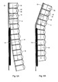
- Fig. 5A This is schematically illustrated in Fig. 5A.
- the chambers 20 can bulge more on their free side remote from the filling apparatus 5 than on their clamped side.
- the free side will shorten more than the clamped side and the string of film material 2 will tend to become warped.
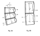
- the angle ⁇ is about 30°. In alternative embodiments, this angle ⁇ may of course be chosen to be larger or smaller, depending on the anticipated warping behavior of the chambers 20 to be filled. This warping behavior inter alia depends on the degree of filling and the dimensions of the chambers 20 to be filled, in particular the width thereof, measured between successive cross sealing seams 22. This is shown in Figs. 6A,B, which clearly show that the angle of curvature ⁇ is larger as the chambers 20 have a smaller width (which can simply be attributed to the afore-described bulging effect).
- the separating apparatus may be equipped with only one circulating element.
- the other circulating element may be replaced by a stationary counter block, along which the film material is moved with the aid of the one circulating element.
- the circulating elements may comprise a driven pressure roller, which may intermittently be brought into and out of contact with the passing film, with the pressure roller being driven at a higher speed than the conveying speed of the film material.
Abstract
Description
- The invention relates to an apparatus for separating interconnected cushions, by breaking weakening lines provided between these cushions.
- Such cushions may, for instance, be manufactured from tubular film material which is divided into chambers by means of cross sealing seams. These chambers are filled with air or another gas or gas mixture and then closed, for instance by sealing. After this, the cushions are separated from one another by the piece or by string, by breaking weakening lines provided in the film material. The separated cushions may, for instance, be used as filling and/or protective material in packagings.
- It is important that the separation of the cushions takes place carefully, in order to prevent them from becoming damaged or springing a leak. In practice, the tearing off is therefore often done manually. This is labor-intensive and therefore undesirable. Further, it is known to separate the cushions mechanically. Here, the edge of the film material is, on both sides of a weakening line to be broken, clamped between two clamping elements, which are then moved apart. Thereby, the weakening line is broken. A drawback of this known apparatus is that the clamping elements need to carry out a relatively complicated movement, in which they are first displaced in the direction of the film material, substantially at right angles to a conveying direction of this film material, are then moved apart, parallel to this conveying direction, and are finally withdrawn again, substantially at right angles to the conveying direction. This requires complex drive means taking up relatively much space.
- The invention contemplates providing an apparatus of the above-described type, where the drawbacks of the known separating apparatus are at least partly obviated. To this end, an apparatus according to the invention is characterized by use of a circulating element having a circulating speed or peripheral speed which is considerably higher than a conveying speed of the interconnected cushions. In this specification, a 'circulating element' is understood to mean an element or element part which is arranged for carrying out a revolution or a circulating movement, such as for instance a belt guided around a number of drive and/or guide rollers or a wheel which can rotate about an axis.
- By temporarily bringing such a circulating element into engagement with one of the cushions, the respective cushion will be carried along at a carrying speed which is much higher than the conveying speed of the adjacent cushions. As a result, the weakening line between this cushion and the adjacent cushions will be subject to a tensile force, which causes the line to break.
- Temporarily bringing the circulating element into engagement can be done relatively simply, for instance by providing the circulating element with a local thickening or cam. With such a circulating element, one rotary engine is sufficient and complex drive mechanisms can be omitted.
- According to an advantageous embodiment, the circulating element may be designed as an endless belt, provided with at least one carrying cam. The conveying means which guide the cushions to the circulating element may also comprise an endless belt. Both belts may be driven by one drive apparatus, in combination with suitable transmission means. Thus, a still simpler arrangement can be obtained. In addition, the endless belts may be arranged in a compact manner, by arranging the endless belt of the circulating element inside the path of travel of the conveyor belt.
- The invention further relates to an assembly of a separating apparatus according to the invention and an apparatus preceding it for inflating and sealing chambers formed in film material. Here, both apparatuses are preferably arranged with respect to each other such that their feed-through directions include an angle. This angle may, for instance, be between about 25° and 45°. Thanks to such an angle, the feed-through direction in the assembly adequately matches the natural movement the film material makes during inflation of the chambers. As a result, undesired (tensile) forces on and/or creasing of the film material can be avoided or reduced.
- According to a further advantageous aspect of the invention, the separating apparatus, at least a feed-through direction thereof, is operatively oriented substantially vertically. As a result, a very compact arrangement can be obtained, at least an apparatus which takes up little space.
- In the further subclaims, further advantageous embodiments of an apparatus according to the invention are described. By way of explanation of the invention, exemplary embodiments of a separating apparatus according to the invention, and the use thereof, will be elucidated with reference to the drawing, in which:
- Fig. 1 shows, in front view, an assembly of an apparatus for manufacturing interconnected air cushions, and a separating apparatus according to the invention;
- Fig. 2 shows the assembly according to Fig. 1, in side elevational view;
- Fig. 3 shows, in top plan view, an example of a specially prepared film material, suitable for use in an assembly according to Figs. 1 and 2;
- Figs. 4A,B show, in more detail, the separating apparatus according to the invention, in front view and side elevational view, respectively, at the moment when the carrying cams engage a cushion to be separated;
- Fig. 4C shows, in side elevational view, the separating apparatus according to Fig. 4B, at a slightly later point in time, where the cushion is partly separated;
- Figs. 5A,B schematically show the assembly according to Fig. 2, without and with bend in the feed-through direction, respectively; and
- Figs. 6A,B schematically show the influence of the cushion dimensions on the curve in the path of travel of the cushions, after they have been filled.
- Figs. 1 and 2 show an
assembly 1 for manufacturing air cushions fromfilm material 2. Thisfilm material 2 may, for instance, be prepared as shown in Fig. 3, where tubular film material is provided withcross sealing seams 22 which divide the film intochambers 20. Thecross sealing seams 22 do not extend over the whole width of thefilm 2, but end at a short distance from one of thelongitudinal edges 24, thereby leaving apassage 25 between thislongitudinal edge 24 and thecross sealing seams 22. Eachcross sealing seam 22 in fact consists of two sealing seams extending substantially parallel at a short distance from each other between which aweakening line 23 is provided, for instance a perforation line. These weakeninglines 23 preferably do extend over the whole width of thetube film 2. - The
assembly 1 comprises asupply provision 3 for supply of thefilm material 2, anapparatus 5 for inflating and sealing the cushions and a separatingapparatus 10 for separating thecushions 20, by the piece or by string. Theassembly 1 further comprises conveying and guide means for guiding thefilm material 2 along above-mentioned apparatuses. - In the exemplary embodiment shown, the
supply provision 3 comprises aspindle 4, suitable for unwinding aroll 6 of film material. Of course, thefilm material 2 may be supplied in a different manner, for instance in a stacked manner, in which case thesupply provision 3 may have a matching shape (not shown). - The
apparatus 5 for inflating and sealing the cushions comprises (as can perhaps most clearly be seen in Fig. 3) a rod-shaped guide element 11 which can extend through thepassage 25 in thefilm material 2, aknife 12 with which alongitudinal edge 24 of thefilm material 2 can be cut open and ablow nozzle 13 and pumping means 14 connected thereto, with which thechambers 20 in thefilm material 2 can be filled with compressed air or another gaseous medium, for instance nitrogen or helium, via the cut-openlongitudinal edge 24. Theapparatus 5 further comprises asealing unit 15, with which thechambers 20 can be sealed with alongitudinal sealing seam 21 directly after filling. To this end, thissealing unit 15 comprises twoelongated sealing blocks 16, which are placed against each other by their large sides. At least one of these large sides is provided with aheating element 19, for instance a sealing thread (as shown in Fig. 3). Around each of theblocks 16, a circulatingbelt 17 may be provided, which is driven in opposite directions (see arrows R1,2) bypulleys 18 and first drive means M1. Thus, the circulatingbelts 17 can carry thefilm material 2 along, clamped between them, in a conveying direction A. In addition, the circulatingbelts 17 can protect thefilm material 2 from direct contact with theheating element 19. - The separating
apparatus 10 comprises circulatingelements 35 for breaking the weakeninglines 23 betweencushions 20 to be separated, and conveying means 30 for guiding thefilm material 2 from the precedingapparatus 5 along these circulatingelements 35. To this end, the conveying means 30 may, for instance, comprise twoendless cords 32, which are each guided along aguide roller 33 and adrive roller 18, and directly abut each other along a part of their circulating paths. Thecords 32 are driven in opposite directions and can thus carry along thefilm material 2 between them at a conveying speed v1. In order to not unnecessarily load thecushions 20 formed in thefilm material 2, thecords 32 preferably engage the edge part of thefilm material 2 between thelongitudinal sealing seam 21 and thelongitudinal edge 24, as can be seen in Figs. 4B and 4C. - In the exemplary embodiment shown, the
cords 32 are driven by thesame pulleys 18 as the circulatingbelts 17 of the inflating and sealingapparatus 5. This limits the number of parts required and, in addition, ensures that a conveying speed v1 of thecords 32 is equal to that of the circulatingbelts 17. As a result, the taking over of thefilm material 2 by thecords 32 can proceed smoothly, without creasing or undesired tensile forces. - In the exemplary embodiment shown, the circulating
elements 35 comprise two circulatingbelts 36, which are each guided around anelongated guide block 37 and twoguide rollers guide block 37. In the exemplary embodiment shown, the circulatingbelts 36 are driven by thelower guide rollers 38 and second drive means M2 engaging them. The drive is such that thebelts 36 are driven in opposite directions, at a speed v2 which is considerably higher than the speed v1 of the conveyingmeans 30. The afore-describedguide roller 33 of the conveyingcords 32 may, as shown, be bearing-mounted on the drive shaft of the second drive means M2 via clearance means suitable for this purpose. - Each
belt 36 is provided with two carryingcams 40, which can temporarily come into engagement with each other and the film material during circulation of thebelts 36, and can thus carry along this film material. Here, the mutual distance between the guide blocks 37 is set such that the carryingcams 40 between theseblocks 37 are pressed against each other, so that thefilm material 2 can be clamped tightly. In order to be able to accurately gear this mutual distance between the guide blocks 37 to the thickness of the carryingcams 40 and thefilm material 2, at least one of these guide blocks 37 is preferably adjustably suspended (as shown in Fig. 1 for the left guide block 37). - The afore-described assembly operates as follows. The
tubular film material 2 is slid over theguide element 11 by opening 25, after whichlongitudinal edge 24 is cut open byknife 12. Then thechambers 20 are filled with air via the just cut-openlongitudinal edge 24 with the aid of theblow nozzle 13. As a result, thechambers 20 will bulge slightly as shown in broken lines in Fig. 4A. Thechambers 20 are then sealed between the sealing blocks 16 of the sealingunit 15, with the formedlongitudinal sealing seam 21 crossing the cross sealing seams 22. Thus, a chain ofair cushions 20 is obtained. This chain is then fed between thecords 32 to the circulatingelements 35 of the separatingapparatus 10. Figs. 4A and 4B show, in front view and side elevational view, respectively, the moment when the carryingcams 40 engage a longitudinal edge of acushion 20A to be separated. Because the conveying speed v2 of the carryingcams 40 is much higher than the conveying speed v1 of thecords 32, a tensile force will be exerted on the weakeningline 23 so that it will be broken on the side of thecams 40. With thecams 40 moving further, thecushion 20A will be pulled loose further and further, as shown in Fig. 4C, until the weakeningline 23 is completely broken. In the meanwhile, thefilm material 2 is moved by thecords 32, at speed v1, so that anew cushion 20B comes between the circulatingelements 35, ready to be separated by the second pair of circulatingcams 40. - The circulating speed of the circulating
elements 35 is preferably geared to the conveying speed v1 of the conveyingmeans 30 and the dimension of the cushions 20 (measured between successive weakening lines 23) such that thecams 40 engage acushion 20 to be separated at a short distance from the weakeningline 23 to be broken (as can clearly be seen in Fig. 4B). Thus, the most effective tensile force can be exerted on therespective weakening line 23 and tensile forces on the cushion itself are minimized. This helps to prevent damage of the cushion. - It goes without saying that, in an alternative embodiment, the circulating
elements 35 may comprise only one carryingcam 40 or comprise more than two carryingcams 40, while the circulating speed may be adjusted accordingly, in order to make the point of application of thecams 40 occur near a weakeningline 23. - Further, with the separating
apparatus 10, string ofmultiple cushions 20 may be separated. To this end, the circulatingelements 35 may be stopped temporarily, so that none of thecams 40 is in engagement with thefilm material 2 until the desired number of cushions has passed. The counting of these cushions may take place automatically, with the aid of detection means known per se, such as a photocell or a counting wheel. Such detection means may also be used to accurately control the circulating speed of circulating elements, so that the carryingcams 40 always engage the film material at a desired moment. - The carrying
cams 40 may be formed integrally with thebelts 36, as local thickenings, or as separate elements, for instance plastic blocks, which may be fixedly connected with thebelts 36. Thecams 40 are preferably provided with an antiskid surface, in order to increase their grip on thefilm material 2. - As can be seen in Figs. 1 and 2, the filling and sealing
apparatus 5 and the separating apparatus are placed one below the other, next to thesupply provision 3. Thus, a very compact arrangement can be obtained. Thefilm material 2 can be guided obliquely upwards from thesupply provision 3 and be guided substantially vertically downwards via adiversion rod 42, to the filling and sealingapparatus 5 and the separatingapparatus 10. As can be seen in the side elevational view of Fig. 2, the filling and sealingapparatus 5 inclines slightly forward with respect to the separatingapparatus 10. As a result, the conveying direction A of thefilm material 2 when passing through the filling and sealingapparatus 5 includes an angle α with the conveying direction B when passing through the separatingapparatus 10. It has been found that such a bend in the conveying direction adequately fits to a 'natural' path that thefilm material 2 wants to follow during passing through theassembly 1. - This is schematically illustrated in Fig. 5A. In this Figure, it can be seen how, during filling, the
chambers 20 can bulge more on their free side remote from the fillingapparatus 5 than on their clamped side. As a result, the free side will shorten more than the clamped side and the string offilm material 2 will tend to become warped. - If this is not taken into account, there is a risk of the string with filled chambers running out of the separating
apparatus 10. In order to prevent this, the clamping force between the conveyingcords 32 can be increased. However, this will cause the forces required for the drive of thesecords 32 to increase as well, which results in a higher energy consumption and a larger load on parts. In addition, this will cause undesired tensile forces to be exerted on thecushions 20, so that they may, for instance, tear or may be separated from each other prematurely. - With the embodiment according to Fig. 2, above behavior is taken into account by placing the respective conveying directions A, B of the filling and sealing
apparatus 5 and the separatingapparatus 10 at an angle α with each other, this angle α preferably corresponding as well as possible with the natural angle of curvature α of the string, as shown in Fig. 5B. - In the exemplary embodiment shown, the angle α is about 30°. In alternative embodiments, this angle α may of course be chosen to be larger or smaller, depending on the anticipated warping behavior of the
chambers 20 to be filled. This warping behavior inter alia depends on the degree of filling and the dimensions of thechambers 20 to be filled, in particular the width thereof, measured between successive cross sealing seams 22. This is shown in Figs. 6A,B, which clearly show that the angle of curvature α is larger as thechambers 20 have a smaller width (which can simply be attributed to the afore-described bulging effect). - The invention is by no means limited to the exemplary embodiments shown in the description and the drawing. All combinations of (parts of) embodiments described and/or shown are understood to fall within the inventive concept. In addition, many variations thereof are possible within the framework of the invention set forth in the claims.
- Thus, the separating apparatus may be equipped with only one circulating element. In that case, the other circulating element may be replaced by a stationary counter block, along which the film material is moved with the aid of the one circulating element. Alternatively, the circulating elements may comprise a driven pressure roller, which may intermittently be brought into and out of contact with the passing film, with the pressure roller being driven at a higher speed than the conveying speed of the film material.
- These and many variations are understood to be within the framework of the invention as set forth in the following claims.
Claims (14)
- A separating apparatus for separating interconnected cushions, by breaking weakening lines provided between these cushions, wherein the apparatus comprises a circulating element and conveying means for carrying the interconnected cushions along this circulating element, wherein the circulating element is arranged for engaging the interconnected cushions at least once during a circulating movement, thereby carrying the engaged cushion along over a part of the circulating movement at a carrying speed which is higher than a conveying speed of the conveying means.
- A separating apparatus according to claim 1, wherein the carrying direction of the circulating element substantially corresponds with the conveying direction of the conveying means.
- A separating apparatus according to claim 1 or 2, wherein the apparatus comprises two circulating elements driven in opposite directions, between which the interconnected cushions can be carried along.
- A separating apparatus according to any one of the preceding claims, wherein the or each circulating element is arranged for engaging a longitudinal edge of the interconnected cushions.
- A separating apparatus according to any one of the preceding claims, wherein the or each circulating element comprises an endless belt, provided with at least one carrying cam, arranged for being in temporary engagement with a cushion to be separated during a circulating movement of the belt.
- A separating apparatus according to any one of the preceding claims, wherein the or each circulating element comprises a driven roller or wheel, arranged for intermittently being brought into and out of contact with cushions to be separated.
- A separating apparatus according to any one of the preceding claims, wherein the conveying means comprise at least one endless belt, arranged for carrying along a longitudinal edge of the interconnected cushions.
- A separating apparatus according to any one of the preceding claims, wherein the conveying means and the at least one circulating element are driven by common drive means.
- An assembly of a separating apparatus according to any one of the preceding claims and an apparatus for inflating and sealing chambers formed in film material, wherein a main feed-through direction along these apparatuses bends where the chambers are inflated or at a short distance thereof.
- An assembly according to claim 9, wherein a feed-through direction of the separating apparatus includes an angle α with a feed-through direction of the apparatus for inflating and sealing the chambers, wherein this angle α is between about 25° and about 45° and is preferably about 30°.
- An assembly according to claim 9 or 10, wherein a feed-through direction of the separating apparatus operatively extends approximately vertically.
- An assembly according to any one of claims 9-11, wherein the separating apparatus is designed as an autonomous module.
- An assembly according to any one of claims 9-11, wherein conveying means of the separating apparatus and conveying means of the apparatus for inflating and sealing the chambers use common drive means.
- An assembly according to any one of claims 9-11, wherein the separating apparatus and the apparatus for inflating and sealing the chambers comprise common conveying means.
Applications Claiming Priority (1)
| Application Number | Priority Date | Filing Date | Title |
|---|---|---|---|
| NL1032097A NL1032097C2 (en) | 2006-06-30 | 2006-06-30 | Device for separating cushions connected to each other, as well as assembly of such a device and a device for manufacturing mutually connected cushions. |
Publications (2)
| Publication Number | Publication Date |
|---|---|
| EP1873065A1 true EP1873065A1 (en) | 2008-01-02 |
| EP1873065B1 EP1873065B1 (en) | 2009-09-09 |
Family
ID=37685071
Family Applications (1)
| Application Number | Title | Priority Date | Filing Date |
|---|---|---|---|
| EP20070111483 Not-in-force EP1873065B1 (en) | 2006-06-30 | 2007-06-29 | Apparatus for separating interconnected cushions, and assembly of such an apparatus and an apparatus for manufacturing interconnected cushions |
Country Status (6)
| Country | Link |
|---|---|
| US (1) | US8100308B2 (en) |
| EP (1) | EP1873065B1 (en) |
| AT (1) | ATE442303T1 (en) |
| DE (1) | DE602007002332D1 (en) |
| ES (1) | ES2333372T3 (en) |
| NL (1) | NL1032097C2 (en) |
Families Citing this family (6)
| Publication number | Priority date | Publication date | Assignee | Title |
|---|---|---|---|---|
| US9994343B2 (en) * | 2013-03-15 | 2018-06-12 | Pregis Innovative Packaging Llc | Replaceable blade |
| JP6329098B2 (en) * | 2015-03-27 | 2018-05-23 | 東洋自動機株式会社 | Bag filling and packaging method and apparatus using double bags |
| JP6896379B2 (en) * | 2015-07-02 | 2021-06-30 | シールド・エアー・コーポレイション(ユーエス) | A system that provides an inflatable cushion |
| CN108820385A (en) * | 2018-07-13 | 2018-11-16 | 武汉智能装备工业技术研究院有限公司 | A kind of intelligent filling device of buffering pneumatic cushion material |
| US11542086B2 (en) | 2018-08-06 | 2023-01-03 | Better Packages, Inc. | Packaging apparatus for film inflation and method thereof |
| CN111820801A (en) * | 2019-04-19 | 2020-10-27 | 韩彪 | Machine for manufacturing roll toilet seat paper and using method thereof |
Citations (3)
| Publication number | Priority date | Publication date | Assignee | Title |
|---|---|---|---|---|
| DE4302567C1 (en) * | 1993-01-29 | 1994-03-17 | Spang & Brands Maschf | Separator for filled bags in filling station - has pairs of conveyor belts, overlapping on transport path with pairs of rollers |
| EP1563987A1 (en) | 2004-02-17 | 2005-08-17 | Sealed Air Corporation (US) | Packaging cushion delivery system |
| WO2006019773A1 (en) * | 2004-07-15 | 2006-02-23 | Storopack, Inc. | Apparatus for and method of producing and/or separating a string of interconnected packing cushions |
Family Cites Families (7)
| Publication number | Priority date | Publication date | Assignee | Title |
|---|---|---|---|---|
| US3675542A (en) * | 1969-07-05 | 1972-07-11 | Yasuhiro Torigoe | Method of manufacturing bags |
| US3938298A (en) * | 1974-05-20 | 1976-02-17 | Minnesota Mining And Manufacturing Company | System for inflation and sealing of air cushions |
| DE3220892A1 (en) * | 1982-06-03 | 1983-12-08 | Icoma Packtechnik GmbH, 7590 Achern | DISCONNECTOR FOR SEPARATING PERFORATED PAPER HOSE SECTIONS |
| US5064408A (en) * | 1990-08-22 | 1991-11-12 | Bridgeman Daniel N P | Method and apparatus for producing a plurality of continuous bags |
| DE4243105C2 (en) * | 1992-12-18 | 1997-08-28 | Windmoeller & Hoelscher | Separating device for separating perforated hose sections |
| US5552003A (en) * | 1994-10-04 | 1996-09-03 | Hoover; Gregory A. | Method for producing inflated dunnage |
| JP2801881B2 (en) * | 1996-02-01 | 1998-09-21 | 日立電子サービス株式会社 | Equipment for manufacturing cushioning members |
-
2006
- 2006-06-30 NL NL1032097A patent/NL1032097C2/en not_active IP Right Cessation
-
2007
- 2007-06-29 DE DE200760002332 patent/DE602007002332D1/en active Active
- 2007-06-29 EP EP20070111483 patent/EP1873065B1/en not_active Not-in-force
- 2007-06-29 AT AT07111483T patent/ATE442303T1/en not_active IP Right Cessation
- 2007-06-29 ES ES07111483T patent/ES2333372T3/en active Active
- 2007-07-02 US US11/772,298 patent/US8100308B2/en not_active Expired - Fee Related
Patent Citations (3)
| Publication number | Priority date | Publication date | Assignee | Title |
|---|---|---|---|---|
| DE4302567C1 (en) * | 1993-01-29 | 1994-03-17 | Spang & Brands Maschf | Separator for filled bags in filling station - has pairs of conveyor belts, overlapping on transport path with pairs of rollers |
| EP1563987A1 (en) | 2004-02-17 | 2005-08-17 | Sealed Air Corporation (US) | Packaging cushion delivery system |
| WO2006019773A1 (en) * | 2004-07-15 | 2006-02-23 | Storopack, Inc. | Apparatus for and method of producing and/or separating a string of interconnected packing cushions |
Also Published As
| Publication number | Publication date |
|---|---|
| DE602007002332D1 (en) | 2009-10-22 |
| NL1032097C2 (en) | 2008-01-02 |
| US20080093407A1 (en) | 2008-04-24 |
| US8100308B2 (en) | 2012-01-24 |
| ATE442303T1 (en) | 2009-09-15 |
| ES2333372T3 (en) | 2010-02-19 |
| EP1873065B1 (en) | 2009-09-09 |
Similar Documents
| Publication | Publication Date | Title |
|---|---|---|
| US8100308B2 (en) | Apparatus for separating interconnected cushions, and assembly of such an apparatus and an apparatus for manufacturing interconnected cushions | |
| JP4327725B2 (en) | Method and apparatus for manufacturing buffer package with packaged article | |
| EP0798249B1 (en) | Method and apparatus for separating a web at a line of weakness | |
| US9434086B2 (en) | Automated air pillow dispenser | |
| US4870802A (en) | Machines and methods for doubling the capacity of packaging machines | |
| US3665673A (en) | Packaging machine and method | |
| ES2738675T3 (en) | Packing machine | |
| US20150069106A1 (en) | Web for making fluid filled units | |
| WO2007144920A1 (en) | Machine and method for packaging groups of products | |
| CN102358445B (en) | The equipment of wrap film and method around stack of articles | |
| ITBO20000733A1 (en) | PILE PACKAGING MACHINE FOR MULTI ITEMS - PAPER PITCH OR SIMILAR WITHIN THE RELATED ENVELOPES OBTAINED FROM WRAPPING SHEETS | |
| US9505189B2 (en) | Apparatus for forming a plurality of flexible pouches from a continuous web of film | |
| RU2697271C1 (en) | Device and method of package degassing | |
| JP4390800B2 (en) | Twist packaging machine | |
| ITPI20080059A1 (en) | MACHINE FOR THE PRODUCTION OF MATERIAL FOR PACKAGING IN THE FORM OF AIR CUSHIONS, OR OTHER GAS, AND ITS METHOD | |
| WO2006036270A2 (en) | Method and apparatus for pre-tearing strings of air-filled packing materials | |
| EP2507049B1 (en) | Blow unit for an apparatus for making air-filled bags, apparatus comprising such a blow unit, system comprising such an apparatus and a method for making air-filled bags | |
| JP7088540B2 (en) | Bag making machine | |
| CN115258299A (en) | Automatic film sleeving machine | |
| WO2014147422A1 (en) | Apparatus to feed a collation of deformable packets to a form/fill/seal machine | |
| CN113924261B (en) | Feeding unit for feeding plastic film | |
| CN210653789U (en) | Continuous stable guiding inflation heat sealing device | |
| KR200290978Y1 (en) | Packing machine using packing film | |
| KR20030080411A (en) | Packing machine using packing film | |
| JPS6212085B2 (en) |
Legal Events
| Date | Code | Title | Description |
|---|---|---|---|
| PUAI | Public reference made under article 153(3) epc to a published international application that has entered the european phase |
Free format text: ORIGINAL CODE: 0009012 |
|
| AK | Designated contracting states |
Kind code of ref document: A1 Designated state(s): AT BE BG CH CY CZ DE DK EE ES FI FR GB GR HU IE IS IT LI LT LU LV MC MT NL PL PT RO SE SI SK TR |
|
| AX | Request for extension of the european patent |
Extension state: AL BA HR MK YU |
|
| 17P | Request for examination filed |
Effective date: 20080523 |
|
| 17Q | First examination report despatched |
Effective date: 20080711 |
|
| AKX | Designation fees paid |
Designated state(s): AT BE BG CH CY CZ DE DK EE ES FI FR GB GR HU IE IS IT LI LT LU LV MC MT NL PL PT RO SE SI SK TR |
|
| GRAP | Despatch of communication of intention to grant a patent |
Free format text: ORIGINAL CODE: EPIDOSNIGR1 |
|
| GRAS | Grant fee paid |
Free format text: ORIGINAL CODE: EPIDOSNIGR3 |
|
| GRAA | (expected) grant |
Free format text: ORIGINAL CODE: 0009210 |
|
| AK | Designated contracting states |
Kind code of ref document: B1 Designated state(s): AT BE BG CH CY CZ DE DK EE ES FI FR GB GR HU IE IS IT LI LT LU LV MC MT NL PL PT RO SE SI SK TR |
|
| REG | Reference to a national code |
Ref country code: GB Ref legal event code: FG4D |
|
| REG | Reference to a national code |
Ref country code: CH Ref legal event code: EP |
|
| REG | Reference to a national code |
Ref country code: IE Ref legal event code: FG4D |
|
| REF | Corresponds to: |
Ref document number: 602007002332 Country of ref document: DE Date of ref document: 20091022 Kind code of ref document: P |
|
| PG25 | Lapsed in a contracting state [announced via postgrant information from national office to epo] |
Ref country code: FI Free format text: LAPSE BECAUSE OF FAILURE TO SUBMIT A TRANSLATION OF THE DESCRIPTION OR TO PAY THE FEE WITHIN THE PRESCRIBED TIME-LIMIT Effective date: 20090909 Ref country code: LT Free format text: LAPSE BECAUSE OF FAILURE TO SUBMIT A TRANSLATION OF THE DESCRIPTION OR TO PAY THE FEE WITHIN THE PRESCRIBED TIME-LIMIT Effective date: 20090909 Ref country code: SE Free format text: LAPSE BECAUSE OF FAILURE TO SUBMIT A TRANSLATION OF THE DESCRIPTION OR TO PAY THE FEE WITHIN THE PRESCRIBED TIME-LIMIT Effective date: 20090909 |
|
| REG | Reference to a national code |
Ref country code: ES Ref legal event code: FG2A Ref document number: 2333372 Country of ref document: ES Kind code of ref document: T3 |
|
| LTIE | Lt: invalidation of european patent or patent extension |
Effective date: 20090909 |
|
| PG25 | Lapsed in a contracting state [announced via postgrant information from national office to epo] |
Ref country code: LV Free format text: LAPSE BECAUSE OF FAILURE TO SUBMIT A TRANSLATION OF THE DESCRIPTION OR TO PAY THE FEE WITHIN THE PRESCRIBED TIME-LIMIT Effective date: 20090909 Ref country code: PL Free format text: LAPSE BECAUSE OF FAILURE TO SUBMIT A TRANSLATION OF THE DESCRIPTION OR TO PAY THE FEE WITHIN THE PRESCRIBED TIME-LIMIT Effective date: 20090909 Ref country code: SI Free format text: LAPSE BECAUSE OF FAILURE TO SUBMIT A TRANSLATION OF THE DESCRIPTION OR TO PAY THE FEE WITHIN THE PRESCRIBED TIME-LIMIT Effective date: 20090909 |
|
| REG | Reference to a national code |
Ref country code: CH Ref legal event code: NV Representative=s name: E. BLUM & CO. AG PATENT- UND MARKENANWAELTE VSP |
|
| PG25 | Lapsed in a contracting state [announced via postgrant information from national office to epo] |
Ref country code: CY Free format text: LAPSE BECAUSE OF FAILURE TO SUBMIT A TRANSLATION OF THE DESCRIPTION OR TO PAY THE FEE WITHIN THE PRESCRIBED TIME-LIMIT Effective date: 20090909 |
|
| PG25 | Lapsed in a contracting state [announced via postgrant information from national office to epo] |
Ref country code: CZ Free format text: LAPSE BECAUSE OF FAILURE TO SUBMIT A TRANSLATION OF THE DESCRIPTION OR TO PAY THE FEE WITHIN THE PRESCRIBED TIME-LIMIT Effective date: 20090909 Ref country code: IS Free format text: LAPSE BECAUSE OF FAILURE TO SUBMIT A TRANSLATION OF THE DESCRIPTION OR TO PAY THE FEE WITHIN THE PRESCRIBED TIME-LIMIT Effective date: 20100109 Ref country code: PT Free format text: LAPSE BECAUSE OF FAILURE TO SUBMIT A TRANSLATION OF THE DESCRIPTION OR TO PAY THE FEE WITHIN THE PRESCRIBED TIME-LIMIT Effective date: 20100111 Ref country code: EE Free format text: LAPSE BECAUSE OF FAILURE TO SUBMIT A TRANSLATION OF THE DESCRIPTION OR TO PAY THE FEE WITHIN THE PRESCRIBED TIME-LIMIT Effective date: 20090909 Ref country code: RO Free format text: LAPSE BECAUSE OF FAILURE TO SUBMIT A TRANSLATION OF THE DESCRIPTION OR TO PAY THE FEE WITHIN THE PRESCRIBED TIME-LIMIT Effective date: 20090909 |
|
| PG25 | Lapsed in a contracting state [announced via postgrant information from national office to epo] |
Ref country code: SK Free format text: LAPSE BECAUSE OF FAILURE TO SUBMIT A TRANSLATION OF THE DESCRIPTION OR TO PAY THE FEE WITHIN THE PRESCRIBED TIME-LIMIT Effective date: 20090909 |
|
| PG25 | Lapsed in a contracting state [announced via postgrant information from national office to epo] |
Ref country code: AT Free format text: LAPSE BECAUSE OF FAILURE TO SUBMIT A TRANSLATION OF THE DESCRIPTION OR TO PAY THE FEE WITHIN THE PRESCRIBED TIME-LIMIT Effective date: 20090909 |
|
| PLBE | No opposition filed within time limit |
Free format text: ORIGINAL CODE: 0009261 |
|
| STAA | Information on the status of an ep patent application or granted ep patent |
Free format text: STATUS: NO OPPOSITION FILED WITHIN TIME LIMIT |
|
| PG25 | Lapsed in a contracting state [announced via postgrant information from national office to epo] |
Ref country code: DK Free format text: LAPSE BECAUSE OF FAILURE TO SUBMIT A TRANSLATION OF THE DESCRIPTION OR TO PAY THE FEE WITHIN THE PRESCRIBED TIME-LIMIT Effective date: 20090909 |
|
| 26N | No opposition filed |
Effective date: 20100610 |
|
| PG25 | Lapsed in a contracting state [announced via postgrant information from national office to epo] |
Ref country code: GR Free format text: LAPSE BECAUSE OF FAILURE TO SUBMIT A TRANSLATION OF THE DESCRIPTION OR TO PAY THE FEE WITHIN THE PRESCRIBED TIME-LIMIT Effective date: 20091210 |
|
| PG25 | Lapsed in a contracting state [announced via postgrant information from national office to epo] |
Ref country code: MC Free format text: LAPSE BECAUSE OF NON-PAYMENT OF DUE FEES Effective date: 20100630 |
|
| PG25 | Lapsed in a contracting state [announced via postgrant information from national office to epo] |
Ref country code: IT Free format text: LAPSE BECAUSE OF NON-PAYMENT OF DUE FEES Effective date: 20100629 |
|
| PG25 | Lapsed in a contracting state [announced via postgrant information from national office to epo] |
Ref country code: IE Free format text: LAPSE BECAUSE OF NON-PAYMENT OF DUE FEES Effective date: 20100629 Ref country code: MT Free format text: LAPSE BECAUSE OF FAILURE TO SUBMIT A TRANSLATION OF THE DESCRIPTION OR TO PAY THE FEE WITHIN THE PRESCRIBED TIME-LIMIT Effective date: 20090909 |
|
| PG25 | Lapsed in a contracting state [announced via postgrant information from national office to epo] |
Ref country code: HU Free format text: LAPSE BECAUSE OF FAILURE TO SUBMIT A TRANSLATION OF THE DESCRIPTION OR TO PAY THE FEE WITHIN THE PRESCRIBED TIME-LIMIT Effective date: 20100310 Ref country code: BG Free format text: LAPSE BECAUSE OF FAILURE TO SUBMIT A TRANSLATION OF THE DESCRIPTION OR TO PAY THE FEE WITHIN THE PRESCRIBED TIME-LIMIT Effective date: 20090909 |
|
| PG25 | Lapsed in a contracting state [announced via postgrant information from national office to epo] |
Ref country code: TR Free format text: LAPSE BECAUSE OF FAILURE TO SUBMIT A TRANSLATION OF THE DESCRIPTION OR TO PAY THE FEE WITHIN THE PRESCRIBED TIME-LIMIT Effective date: 20090909 |
|
| REG | Reference to a national code |
Ref country code: FR Ref legal event code: PLFP Year of fee payment: 9 |
|
| REG | Reference to a national code |
Ref country code: FR Ref legal event code: PLFP Year of fee payment: 10 |
|
| REG | Reference to a national code |
Ref country code: FR Ref legal event code: PLFP Year of fee payment: 11 |
|
| REG | Reference to a national code |
Ref country code: FR Ref legal event code: PLFP Year of fee payment: 12 |
|
| PGFP | Annual fee paid to national office [announced via postgrant information from national office to epo] |
Ref country code: LU Payment date: 20180620 Year of fee payment: 12 Ref country code: CH Payment date: 20180621 Year of fee payment: 12 Ref country code: DE Payment date: 20180625 Year of fee payment: 12 |
|
| PGFP | Annual fee paid to national office [announced via postgrant information from national office to epo] |
Ref country code: BE Payment date: 20180620 Year of fee payment: 12 Ref country code: FR Payment date: 20180620 Year of fee payment: 12 Ref country code: NL Payment date: 20180522 Year of fee payment: 12 |
|
| PGFP | Annual fee paid to national office [announced via postgrant information from national office to epo] |
Ref country code: IT Payment date: 20180627 Year of fee payment: 12 Ref country code: ES Payment date: 20180724 Year of fee payment: 12 Ref country code: GB Payment date: 20180620 Year of fee payment: 12 |
|
| REG | Reference to a national code |
Ref country code: DE Ref legal event code: R119 Ref document number: 602007002332 Country of ref document: DE |
|
| REG | Reference to a national code |
Ref country code: CH Ref legal event code: PL |
|
| REG | Reference to a national code |
Ref country code: NL Ref legal event code: MM Effective date: 20190701 |
|
| GBPC | Gb: european patent ceased through non-payment of renewal fee |
Effective date: 20190629 |
|
| REG | Reference to a national code |
Ref country code: BE Ref legal event code: MM Effective date: 20190630 |
|
| PG25 | Lapsed in a contracting state [announced via postgrant information from national office to epo] |
Ref country code: NL Free format text: LAPSE BECAUSE OF NON-PAYMENT OF DUE FEES Effective date: 20190701 Ref country code: IT Free format text: LAPSE BECAUSE OF NON-PAYMENT OF DUE FEES Effective date: 20190629 Ref country code: GB Free format text: LAPSE BECAUSE OF NON-PAYMENT OF DUE FEES Effective date: 20190629 Ref country code: DE Free format text: LAPSE BECAUSE OF NON-PAYMENT OF DUE FEES Effective date: 20200101 |
|
| PG25 | Lapsed in a contracting state [announced via postgrant information from national office to epo] |
Ref country code: LI Free format text: LAPSE BECAUSE OF NON-PAYMENT OF DUE FEES Effective date: 20190630 Ref country code: CH Free format text: LAPSE BECAUSE OF NON-PAYMENT OF DUE FEES Effective date: 20190630 Ref country code: BE Free format text: LAPSE BECAUSE OF NON-PAYMENT OF DUE FEES Effective date: 20190630 Ref country code: LU Free format text: LAPSE BECAUSE OF NON-PAYMENT OF DUE FEES Effective date: 20190629 |
|
| PG25 | Lapsed in a contracting state [announced via postgrant information from national office to epo] |
Ref country code: FR Free format text: LAPSE BECAUSE OF NON-PAYMENT OF DUE FEES Effective date: 20190630 |
|
| REG | Reference to a national code |
Ref country code: ES Ref legal event code: FD2A Effective date: 20201029 |
|
| PG25 | Lapsed in a contracting state [announced via postgrant information from national office to epo] |
Ref country code: ES Free format text: LAPSE BECAUSE OF NON-PAYMENT OF DUE FEES Effective date: 20190630 |