EP1872706A1 - Verfahren zum Herstellen eines Endoskops sowie derartiges Endoskop - Google Patents
Verfahren zum Herstellen eines Endoskops sowie derartiges Endoskop Download PDFInfo
- Publication number
- EP1872706A1 EP1872706A1 EP07012791A EP07012791A EP1872706A1 EP 1872706 A1 EP1872706 A1 EP 1872706A1 EP 07012791 A EP07012791 A EP 07012791A EP 07012791 A EP07012791 A EP 07012791A EP 1872706 A1 EP1872706 A1 EP 1872706A1
- Authority
- EP
- European Patent Office
- Prior art keywords
- endoscope
- tube
- endoscope head
- distal end
- proximal end
- Prior art date
- Legal status (The legal status is an assumption and is not a legal conclusion. Google has not performed a legal analysis and makes no representation as to the accuracy of the status listed.)
- Granted
Links
Images




Classifications
-
- A—HUMAN NECESSITIES
- A61—MEDICAL OR VETERINARY SCIENCE; HYGIENE
- A61B—DIAGNOSIS; SURGERY; IDENTIFICATION
- A61B1/00—Instruments for performing medical examinations of the interior of cavities or tubes of the body by visual or photographical inspection, e.g. endoscopes; Illuminating arrangements therefor
- A61B1/00064—Constructional details of the endoscope body
- A61B1/0011—Manufacturing of endoscope parts
-
- A—HUMAN NECESSITIES
- A61—MEDICAL OR VETERINARY SCIENCE; HYGIENE
- A61B—DIAGNOSIS; SURGERY; IDENTIFICATION
- A61B1/00—Instruments for performing medical examinations of the interior of cavities or tubes of the body by visual or photographical inspection, e.g. endoscopes; Illuminating arrangements therefor
-
- A—HUMAN NECESSITIES
- A61—MEDICAL OR VETERINARY SCIENCE; HYGIENE
- A61B—DIAGNOSIS; SURGERY; IDENTIFICATION
- A61B1/00—Instruments for performing medical examinations of the interior of cavities or tubes of the body by visual or photographical inspection, e.g. endoscopes; Illuminating arrangements therefor
- A61B1/00064—Constructional details of the endoscope body
-
- A—HUMAN NECESSITIES
- A61—MEDICAL OR VETERINARY SCIENCE; HYGIENE
- A61B—DIAGNOSIS; SURGERY; IDENTIFICATION
- A61B1/00—Instruments for performing medical examinations of the interior of cavities or tubes of the body by visual or photographical inspection, e.g. endoscopes; Illuminating arrangements therefor
- A61B1/00064—Constructional details of the endoscope body
- A61B1/00071—Insertion part of the endoscope body
-
- A—HUMAN NECESSITIES
- A61—MEDICAL OR VETERINARY SCIENCE; HYGIENE
- A61B—DIAGNOSIS; SURGERY; IDENTIFICATION
- A61B1/00—Instruments for performing medical examinations of the interior of cavities or tubes of the body by visual or photographical inspection, e.g. endoscopes; Illuminating arrangements therefor
- A61B1/00064—Constructional details of the endoscope body
- A61B1/00071—Insertion part of the endoscope body
- A61B1/0008—Insertion part of the endoscope body characterised by distal tip features
-
- A—HUMAN NECESSITIES
- A61—MEDICAL OR VETERINARY SCIENCE; HYGIENE
- A61B—DIAGNOSIS; SURGERY; IDENTIFICATION
- A61B1/00—Instruments for performing medical examinations of the interior of cavities or tubes of the body by visual or photographical inspection, e.g. endoscopes; Illuminating arrangements therefor
- A61B1/00064—Constructional details of the endoscope body
- A61B1/00071—Insertion part of the endoscope body
- A61B1/0008—Insertion part of the endoscope body characterised by distal tip features
- A61B1/00096—Optical elements
-
- A—HUMAN NECESSITIES
- A61—MEDICAL OR VETERINARY SCIENCE; HYGIENE
- A61B—DIAGNOSIS; SURGERY; IDENTIFICATION
- A61B1/00—Instruments for performing medical examinations of the interior of cavities or tubes of the body by visual or photographical inspection, e.g. endoscopes; Illuminating arrangements therefor
- A61B1/002—Instruments for performing medical examinations of the interior of cavities or tubes of the body by visual or photographical inspection, e.g. endoscopes; Illuminating arrangements therefor having rod-lens arrangements
-
- F—MECHANICAL ENGINEERING; LIGHTING; HEATING; WEAPONS; BLASTING
- F16—ENGINEERING ELEMENTS AND UNITS; GENERAL MEASURES FOR PRODUCING AND MAINTAINING EFFECTIVE FUNCTIONING OF MACHINES OR INSTALLATIONS; THERMAL INSULATION IN GENERAL
- F16L—PIPES; JOINTS OR FITTINGS FOR PIPES; SUPPORTS FOR PIPES, CABLES OR PROTECTIVE TUBING; MEANS FOR THERMAL INSULATION IN GENERAL
- F16L13/00—Non-disconnectable pipe joints, e.g. soldered, adhesive, or caulked joints
- F16L13/14—Non-disconnectable pipe joints, e.g. soldered, adhesive, or caulked joints made by plastically deforming the material of the pipe, e.g. by flanging, rolling
- F16L13/147—Non-disconnectable pipe joints, e.g. soldered, adhesive, or caulked joints made by plastically deforming the material of the pipe, e.g. by flanging, rolling by radially expanding the inner part
-
- G—PHYSICS
- G02—OPTICS
- G02B—OPTICAL ELEMENTS, SYSTEMS OR APPARATUS
- G02B23/00—Telescopes, e.g. binoculars; Periscopes; Instruments for viewing the inside of hollow bodies; Viewfinders; Optical aiming or sighting devices
- G02B23/24—Instruments or systems for viewing the inside of hollow bodies, e.g. fibrescopes
- G02B23/2476—Non-optical details, e.g. housings, mountings, supports
Definitions
- the invention relates to a method for producing an endoscope, the endoscope having an endoscope head and an optic tube, with the steps of providing the endoscope head, providing the optics tube and inserting a proximal end region of the optic tube into a distal end region of the endoscope head.
- the invention further relates to an endoscope with an endoscope head and an optics tube.
- an endoscope is used primarily in minimally invasive surgery to examine body cavities or hollow organs.
- an endoscope has an endoscope head, on whose distal end an elongate endoscope shaft is arranged, which has an optical tube. Connections for an external illumination source and irrigation / suction lines and an eyecup can be provided on the endoscope head. It is coupled via the connection for the illumination source light in a light guide system, which extends through the endoscope head and the endoscope shaft, and guided to the distal end of the endoscope shaft.
- the endoscope has an optical system for imaging.
- the imaging optics may consist of optical fibers, rod lenses o.a. be manufactured, but also have an image sensor with electrical signal transmission.
- Endoscopes may be rigid or flexible depending on the material of the endoscope.
- a rigid endoscope has a shaft made of a non-flexible material, such as. Stainless steel or metal on.
- a distal end portion of the endoscope is inserted therein while the endoscope head and the portion of the endoscope shaft that is not inserted into the body cavity remain outside the body.
- the manufacture of an endoscope includes, among other things, connecting a proximal end portion of the shaft to a distal end portion of the endoscope head.
- Known methods are based on providing the endoscope head and the optics tube of the endoscope and inserting both into one another such that the optic tube is received with its proximal end region in the distal end region of the endoscope head.
- the contact surfaces of both end regions are joined together by soldering, welding or gluing.
- a disadvantage of these known methods is that the connection of the endoscope head and the optics tube is technically very complicated. In the manufacturing process of the endoscope corresponding machinery must be provided, which allow a welding, soldering or bonding of the contact surfaces of the endoscope head and the optics tube. Furthermore, these known methods to connect the endoscope head with the optics tube, very time consuming. In particular, when gluing both endoscope components care must be taken that the optics tube and the endoscope head are held in position until the adhesive has dried.
- a further disadvantage of these methods is the difficulty of keeping the optics tube and the endoscope head exactly positioned relative to one another during the production process, so that the length of the endoscope can be reproduced. If the resulting total length of the manufactured endoscope deviates minimally from the desired nominal length, this difference in length must be taken into account when forming the light guidance system and the imaging optics.
- the object with regard to the method mentioned at the outset is achieved by compressing the distal end region of the endoscope head with the proximal end region of the optic tube.
- the object with regard to the endoscope mentioned above is achieved according to the invention in that a proximal end region of the optic tube is pressed with a distal end region of the endoscope head.
- the inventive method and the endoscope according to the invention enable a technically very simple connection between the endoscope head and the optics tube.
- a pressing of the two endoscope components advantageously requires no further aids, such as e.g. Solder or glue.
- the method according to the invention can be carried out more time-saving than soldering, welding or gluing the endoscope head to the optics tube. Therefore, during the manufacture of the endoscope, process steps such as cooling or drying of the connection between the endoscope head and the optics tube are eliminated.
- connection between the optics tube and the endoscope head is stable and time-resistant. Since both endoscope components are pressed together, the endoscope is insensitive to external influences, such as water. Consequently, the optic tube does not loosen after many cleaning processes of the endoscope, so that costly repairs are avoided.
- the compression of the endoscope head with the optics tube allows a stable connection of both components.
- the endoscope advantageously also withstands strong bending stresses on the optics tube, which generate a high level of leverage on the optics tube.
- the proximal end region of the optic tube is compressed by upsetting.
- This measure represents a structurally easy to implement compression of the optic tube with the endoscope head. Since the wall thickness of the optic tube is less than that of the endoscope head, the optic tube is better for a compression process than the endoscope head for a squeezing.
- the optic tube is held axially fixed during pressing, and an axial force is exerted in the direction of a distal end region of the optic tube on the proximal end region of the optic tube.
- This measure has the advantage that the compression of the optic tube with the endoscope head is achieved in a simple manner in that the inserted optic tube is held distally on the endoscope head and at the same time an axial force acting in the direction of the distal end of the optic tube, this is applied , The proximal end portion of the optic tube is thereby compressed and pressed with the endoscope head.
- the axial force is provided by a pressing tool, in particular a mandrel.
- the distal end region of the endoscope head is provided on the inside with a circumferential puncture into which material of the optic tube flows in a positive fit during pressing.
- This measure has the advantage that the optics tube in the endoscope head is kept axially particularly secure by engaging material of the optics tube into the groove of the endoscope head. Tensile and compressive forces on the optics tube in the axial direction do not lead to a change in position of the optics tube with respect to the endoscope head.
- the circumferential recess is provided as a full circumferential groove.
- the distal end region of the endoscope head is provided with at least one circumferentially delimited bulge into which material of the optic tube flows in a form-fitting manner during pressing.
- This measure has the advantage that the material inserted into the circumferentially limited recess prevents the optics tube from becoming relative to the endoscope head can twist around its longitudinal axis. This results in a simple way a rotation of the optics tube.
- a proximal end of the optics tube is widened in a trumpet-like manner.
- This measure has the advantage that the proximal end of the optic tube points away from the longitudinal axis of the optic tube. If light guides are introduced through the optics tube and the endoscope head during a further assembly, it is advantageously prevented that they are damaged, for example, buckling or breaking.
- the distal end region of the endoscope head is adhesively bonded to the proximal end region of the optical tube after the compression.
- This measure has the advantage that the endoscope is protected against external influences, such as e.g. Water, being sealed.
- the adhesive does not have to apply the holding force for the firm connection between the optic tube and the endoscope head, as in the known methods, so that the adhesive point does not constitute a predetermined breaking point.
- FIG. 1 an endoscope provided with the general reference numeral 10 is shown.
- the endoscope 10 has an endoscope head 12 and an endoscope shaft 14.
- Such an endoscope 10 is used, for example, in minimally invasive surgery for the examination of body cavities or hollow organs.
- the endoscope 10 is inserted distally into a body opening, so that at least the endoscope head 12 remains outside the body.
- the endoscope shaft 14 has an elongated optical tube 16, the proximal end region 18 of which is connected to a distal end region 20 of the endoscope head 12.
- the optical tube 16 is preferably designed as a cylindrical hollow cylinder with a small wall thickness.
- a connection 22 for an external illumination source and an eyecup 24 are arranged at the endoscope head 12.
- a light guide system is further included, which extends from the terminal 22 to a distal end portion 26 of the optical tube 16 and is made of optical fibers.
- the light guide system is used to illuminate an operating area within the body opening.
- an imaging system is received that extends from the eyecup 24 to the distal end portion 26 of the optic tube 16.
- the imaging system may comprise optical fibers, rod lenses or even an image sensor with electrical signal transmission.
- the endoscope 10 is preferably rigid, wherein the optical tube 16 is made of non-flexible materials, such as steel or metal.
- the optic tube 16 and the endoscope head 12 are provided in a first method step (see FIG. 2).
- the endoscope head 12 has an inner side at its distal end portion 20 a circumferential groove 28 and at least one circumferentially limited bulge 30 on.
- the recess 28 is preferably formed as a full circumferential groove 32 in the distal end portion 20 of the endoscope head 12.
- the bulge 30 can either be arranged directly on a part of the recess 28 or be spatially separated from it in the distal end area 20 of the endoscope head 12. Furthermore, the bulge 30 seen in the radial direction of the distal end portion 20 of the endoscope head 12 can be recessed relative to the groove 28.
- An outer diameter 34 of the optic tube 16 is sized to be slightly smaller than an inner diameter 36 of the distal end portion 20 of the endoscope head 12.
- the proximal end region 18 of the optic tube 16 is inserted along a direction of an arrow 38 into the distal end region 20 of the endoscope head 12.
- an outer surface 40 of the optic tube 16 contacts an inner surface 42 of the endoscope head 12 or the outer surface 40 of the optic tube 16 is slightly spaced from the inner surface 42 of the distal end portion 20 of the Endoskopfkopfs 12.
- the proximal end portion 18 of the optic tube 16 so far in the distal Inserted end portion 20 of the endoscope head 12 that at least one proximal end 44 of the optical tube 16 extends beyond the puncture 28 and the bulge 30.
- FIGS. 4-8 show the compression of the distal end region 20 of the endoscope head 12 with the proximal end region 18 of the optic tube 16.
- the optic tube 16, the proximal end portion 18 of which is inserted into the distal end region 20 of the endoscope head 12, is held in an axially fixed position with respect to tensile and compressive forces pointing in the axial direction of the optic tube 16 (see FIG. 4).
- the optical tube 16 is clamped in a holding device 46.
- a Holding device 46 may, for example, two jaws 48, 50 which engage the outer surface 40 of the inserted optical tube 16 distal side of the distal end portion 20 of the endoscope head 12.
- the two jaws 48, 50 either touch the distal end portion 20 of the endoscope head 12 or are slightly spaced therefrom.
- the jaws 48, 50 of the holding device 46 are shown in Fig. 4, while they are not shown in FIG. 5-8 for the sake of clarity.
- An axial force is exerted on the proximal end region 18 of the optical tube 16 in the direction of an arrow 52.
- the axial force is generated by means of a pressing tool 54, which is introduced into the optical tube 16 on the proximal side by the endoscope head 12.
- the pressing tool 54 may preferably be formed as a cylindrical mandrel 56.
- the pressing tool 54 tapers at a distal end 58, so that an outer diameter 60 of the distal end 58 of the pressing tool 54 is slightly smaller than an inner diameter 62 of the optical tube 16 is formed.
- the pressing tool 54 has a preferably full-circumference planar surface 64, which is formed transversely to a longitudinal axis 66 of the pressing tool 54, on which the proximal end 44 of the optical tube 16 comes to rest completely.
- the distal end 58 of the grooving tool 54 is formed so long that the grooving tool 54 is in a fully retracted condition, i. when the planar surface 64 contacts the proximal end 44 of the optic tube 16, passes over the puncture 28 and the bulge 30.
- the proximal end portion 18 of the optical tube 16 is compressed by the axial force such that compressed material is displaced radially outward. This is the case, in particular, when the distal end 58 of the pressing tool 54 extends beyond the puncture 28 and the bulge 30 and thus prevents a radially inwardly directed displacement of the compressed material.
- material of the proximal end region 18 of the optical tube 16 engages positively in the puncture 28, while the optical tube 16 with the endoscope head 12th is pressed.
- the engagement of the material of the optic tube 16 in the groove 28 allows a secure axial positional fixation of the optic tube 16 with respect to the endoscope head 12th
- the proximal end 44 of the optical tube 16 is widened like a trumpet, so that the outer diameter 34 of the optical tube 16 increases at this point.
- the proximal end 44 of the optic tube 16 faces outward from a longitudinal axis of the optic tube 16.
- the pressing tool 54 is removed from the optics tube 16 and the endoscope head 12.
- a further pressing tool 68 is inserted in the direction of the arrow 52 through the endoscope head 12 into the compressed optical tube 16, with which an axial force is generated on the proximal end region 18 of the optical tube 16.
- the further pressing tool 68 also tapers distally, wherein the taper is not stepped, but extends over a concavely curved portion of a distal end 70.
- a smallest outer diameter 72 of the distal end 70 of the further pressing tool 68 is likewise formed slightly smaller than the inner diameter 62 of the optical tube 16.
- the tapered distal end 70 of the further grooving tool 68 expands the proximal end 44 of the optic tube 16 such that a shape of the proximal end 44 of the optic tube 16 conforms to a shape of the distal end 70 of the further grout 68.
- the pressing tool 54 and the pressing tool 68 can also be designed as a pressing tool with which the proximal end region 18 of the optic tube 16 can both be compressed and the proximal end 44 of the optic tube 16 can be widened.
- the flared proximal end 44 of the optic tube 16 prevents subsequent damage to the latter when optical fibers are inserted into the endoscope 10 later.
- the proximal end region 18 of the optic tube 16 is further adhesively bonded to the distal end region 20 of the endoscope head 12 after the compression.
- an adhesive is applied to the outer surface 40 of the optic tube 16 and / or on the inner surface 42 of the distal end portion 20 of the endoscope head 12-
- the bonding of the optic tube 16 with the endoscope head 12 serves to seal the junction of both endoscope parts against external influences, such as. Water.
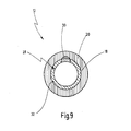
- FIG. 9 shows a cross-sectional drawing of the distal end region 20 of the endoscope head 12 along the line I-I in FIG. 8.
- the proximal end region 18 of the optic tube 16 is pressed with the distal end region 20 of the endoscope head 12.
- Material of the optical tube 16 engages positively in the fully circumferential groove 32 formed recess 28 and in the bulge 30 a.
Landscapes
- Health & Medical Sciences (AREA)
- Life Sciences & Earth Sciences (AREA)
- Surgery (AREA)
- Engineering & Computer Science (AREA)
- Physics & Mathematics (AREA)
- Optics & Photonics (AREA)
- Medical Informatics (AREA)
- General Health & Medical Sciences (AREA)
- Pathology (AREA)
- Nuclear Medicine, Radiotherapy & Molecular Imaging (AREA)
- Biomedical Technology (AREA)
- Heart & Thoracic Surgery (AREA)
- Biophysics (AREA)
- Molecular Biology (AREA)
- Animal Behavior & Ethology (AREA)
- Radiology & Medical Imaging (AREA)
- Public Health (AREA)
- Veterinary Medicine (AREA)
- General Engineering & Computer Science (AREA)
- Manufacturing & Machinery (AREA)
- Mechanical Engineering (AREA)
- Astronomy & Astrophysics (AREA)
- General Physics & Mathematics (AREA)
- Endoscopes (AREA)
Abstract
Description
- Die Erfindung betrifft ein Verfahren zum Herstellen eines Endoskops, wobei das Endoskop einen Endoskopkopf und ein Optikrohr aufweist, mit den Schritten Bereitstellen des Endoskopkopfs, Bereitstellen des Optikrohrs und Einschieben eines proximalen Endbereichs des Optikrohrs in einen distalen Endbereich des Endoskopkopfs.
- Die Erfindung betrifft ferner ein Endoskop mit einem Endoskopkopf und einem Optikrohr.
- Ein derartiges Verfahren sowie ein Endoskop, das durch dieses Verfahren hergestellt ist, sind allgemein bekannt.
- Endoskope werden vor allem in der minimal-invasiven Chirurgie verwendet, um Körperhohlräume oder Hohlorgane zu untersuchen. Hierzu weist ein Endoskop einen Endoskopkopf auf, an dessen distalen Ende ein langerstreckter Endoskopschaft angeordnet ist, der ein Optikrohr aufweist. Am Endoskopkopf können Anschlüsse für eine externe Beleuchtungsquelle und Spül-/Saugleitungen sowie eine Augenmuschel vorgesehen sein. Es wird über den Anschluss für die Beleuchtungsquelle Licht in ein Lichtleitsystem, das durch den Endoskopkopf und den Endoskopschaft reicht, eingekoppelt und zu dem distalen Ende des Endoskopschafts geführt. Ferner weist das Endoskop eine Optik zur Bildgebung auf. Die Bildgebungsoptik kann aus Lichtleitfasern, Stablinsen o.a. gefertigt sein, aber auch einen Bildsensor mit elektrischer Signalübertragung aufweisen.
- Endoskope können je nach Material des Endoskopschafts starr oder flexibel ausgebildet sein. Ein starres Endoskop weist einen Schaft aus einem nicht biegsamen Material, wie bspw. Edelstahl oder Metall, auf.
- Zur Untersuchung eines Körperhohlraums wird ein distaler Endbereich des Endoskops in diesen eingeführt, während der Endoskopkopf und der Teil des Endoskopschafts, der nicht in den Körperhohlraum eingeführt ist, außerhalb des Körpers verbleibt.
- Die Herstellung eines Endoskops umfasst unter anderem das Verbinden eines proximalen Endbereichs des Schafts mit einem distalen Endbereich des Endoskopkopfs.
- Bekannte Verfahren gehen davon aus, den Endoskopkopf und das Optikrohr des Endoskops bereitzustellen und beide derart ineinander einzuschieben, dass das Optikrohr mit seinem proximalen Endbereich in dem distalen Endbereich des Endoskopkopfs aufgenommen ist. Die Berührflächen beider Endbereiche werden durch Löten, Schweißen oder Verkleben miteinander verbunden.
- Nachteilig an diesen bekannten Verfahren ist, dass das Verbinden des Endoskopkopfs und des Optikrohrs technisch sehr aufwändig ist. Im Fertigungsprozess des Endoskops müssen entsprechende Maschinen bereitgestellt werden, die ein Verschweißen, Verlöten oder verkleben der Berührflächen des Endoskopkopfs und des Optikrohrs ermöglichen. Ferner sind diese bekannten Verfahren, den Endoskopkopf mit dem Optikrohr zu verbinden, sehr zeitaufwändig. Insbesondere muss beim Verkleben beider Endoskopbauteile darauf geachtet werden, dass das Optikrohr und der Endoskopkopf so lange lagefest gehalten werden, bis der Klebstoff getrocknet ist.
- Ein weiterer Nachteil dieser Verfahren ist die Schwierigkeit, das Optikrohr und den Endoskopkopf beim Herstellungsprozess zueinander exakt positioniert zu halten, so dass die Länge des Endoskops reproduzierbar ist. Weicht die sich ergebende Gesamtlänge des hergestellten Endoskops minimal von der gewünschten Solllänge ab, muss dieser Längenunterschied beim Ausbilden des Lichtleitsystems und der Bildgebungsoptik berücksichtigt werden.
- Ferner ist es bei den bekannten Herstellungsverfahren mittels Schweißen und Löten nachteilig, dass während des Herstellungsprozesses Wärme im Bereich der Verbindungsstelle beider Endoskopbauteile entsteht. Durch die Erwärmung des Materials des Optikrohrs kann dieses spröde werden, wodurch die Festigkeit des Optikrohrs im Bereich der Wärmeinwirkung herabgesetzt wird, so dass das Optikrohr bereits bei leichten Biegebeanspruchungen brechen kann,
- Ferner erweist es sich als Nachteil, dass bei Endoskopen, die mittels der bekannten Verfahren hergestellt sind, die Verbindung zwischen dem Endoskopkopf und dem Optikrohr nicht stabil ausgebildet ist. Wird das Optikrohr während einer Operation infolge einer Biegebeanspruchung einer starken Hebelkraft ausgesetzt, ist es möglich, dass das Endoskop an der Verbindungsstelle, d.h. der Sch`weiß-, Löt- oder Klebestelle, zwischen dem Endoskopkopf und dem Optikrohr bricht.
- Es ist daher eine Aufgabe der vorliegenden Erfindung, hier Abhilfe zu schaffen und ein Verfahren der eingangs genannten Art bereitzustellen, das eine technisch einfach realisierbare und stabile Verbindung zwischen dem Endoskopkopf und dem Optikrohr ermöglicht.
- Es ist ferner eine Aufgabe der vorliegenden Erfindung, ein Endoskop der eingangs genannten Art bereitzustellen, bei dem der Endoskopkopf konstruktiv einfach und stabil mit dem Optikrohr verbunden ist.
- Erfindungsgemäß wird die Aufgabe hinsichtlich des eingangs genannten Verfahrens dadurch gelöst, dass der distale Endbereich des Endoskopkopfs mit dem proximalen Endbereich des Optikrohrs verpresst wird.
- Des Weiteren wird die Aufgabe hinsichtlich des eingangs genannten Endoskops erfindungsgemäß dadurch gelöst, dass ein proximaler Endbereich des Optikrohrs mit einem distalen Endbereich des Endoskopkopfs verpresst ist.
- Das erfindungsgemäße Verfahren und das erfindungsgemäße Endoskop ermöglichen eine technisch sehr einfache Verbindung zwischen dem Endoskopkopf und dem Optikrohr. Ein Verpressen der beiden Endoskopbauteile bedarf vorteilhafterweise keiner weiteren Hilfsmittel, wie z.B. Lötzinn oder Klebstoff. Ferner kann das erfindungsgemäße Verfahren zeitsparender als ein Verlöten, Verschweißen oder Verkleben des Endoskopkopfs mit dem Optikrohr durchgeführt werden. Daher entfallen bei der Fertigung des Endoskops Prozessschritte wie Abkühlen oder Trocknen der Verbindungsstelle zwischen dem Endoskopkopf und dem Optikrohr.
- Durch das Verpressen des Optikrohrs mit dem Endoskopkopf, das kalt bzw. ohne Erwärmung durchgeführt werden kann, entstehen auch keine Materialschwächungen durch Wärmeeinflüsse, wie dies beim Schweißen oder Löten der Fall ist.
- Ein weiterer Vorteil des erfindungsgemäßen Verfahrens gegenüber den bekannten Verfahren ergibt sich aus der Tatsache, dass die Verbindung zwischen dem Optikrohr und dem Endoskopkopf stabil und zeitlich beständig ausgebildet ist. Da beide Endoskopbauteile miteinander verpresst sind, ist das Endoskop gegenüber äußeren Einflüssen, wie zum Beispiel Wasser, unempfindlich. Folglich lockert sich das Optikrohr auch nicht nach vielen Reinigungsprozessen des Endoskops, so dass kostenintensive Reparaturen vermieden werden.
- Ferner ermöglicht das Verpressen des Endoskopkopfs mit dem Optikrohr eine stabile Verbindung beider Bauteile. Hierdurch hält das Endoskop vorteilhafterweise auch starken Biegebeanspruchungen des Optikrohrs stand, die eine große Hebelkraft auf das Optikrohr erzeugen.
- In einer bevorzugten Ausgestaltung wird der proximale Endbereich des Optikrohrs durch Stauchen verpresst.
- Diese Maßnahme stellt eine konstruktiv einfach zu realisierende Verpressung des Optikrohrs mit dem Endoskopkopf dar. Da die Wandstärke des Optikrohrs geringer ist als derjenige des Endoskopkopfs, eignet sich das Optikrohr für einen Stauchungsvorgang besser als der Endoskopkopf für einen Quetschvorgang.
- In einer weiteren bevorzugten Ausgestaltung wird das Optikrohr beim Verpressen axial lagefest gehalten, und es wird eine axiale Kraft in Richtung eines distalen Endbereichs des Optikrohrs auf den proximalen Endbereich des Optikrohrs ausgeübt.
- Diese Maßnahme hat den Vorteil, dass das Verpressen des Optikrohrs mit dem Endoskopkopf auf einfache Weise dadurch erreicht wird, dass das eingeschobene Optikrohr distalseitig des Endoskopkopfs gehalten wird und gleichzeitig eine axiale Kraft, die in Richtung des distalen Endes des Optikrohrs wirkt, auf dieses beaufschlagt wird. Der proximale Endbereich des Optikrohrs wird dadurch gestaucht und mit dem Endoskopkopf verpresst.
- In einer weiteren bevorzugten Ausgestaltung wird die axiale Kraft durch ein Verpresswerkzeug, insbesondere einen Dorn, bereitgestellt.
- Diese Maßnahme stellt eine technisch einfache Möglichkeit dar, wie die axiale Kraft auf das Optikrohr erzeugt wird. Im Unterschied zu den bekannten Verfahren ist der Werkzeugaufwand wesentlich geringer.
- In einer weiteren bevorzugten Ausgestaltung wird der distale Endbereich des Endoskopkopfs innenseitig mit einem umfänglichen Einstich bereitgestellt, in den beim Verpressen Material des Optikrohrs formschlüssig einfließt.
- Diese Maßnahme hat den Vorteil, dass das Optikrohr in dem Endoskopkopf axial besonders sicher gehalten wird, indem Material des Optikrohrs in den Einstich des Endoskopkopfs eingreift. Zug- und Druckkräfte auf das Optikrohr in axialer Richtung führen nicht zu einer Lageänderung des Optikrohrs bezüglich des Endoskopkopfs.
- In einer weiteren bevorzugten Ausgestaltung wird der umfängliche Einstich als vollumfängliche Nut bereitgestellt.
- Diese Maßnahme hat den Vorteil, dass aufgrund dieser Formgebung des Einstichs besonders viel Material in den Einstich eingreifen kann. Die Verbindung des Endoskopkopfs mit dem Optikrohr ist daher besonders stabil ausgebildet.
- In einer weiteren bevorzugten Ausgestaltung wird der distale Endbereich des Endoskopkopfs mit zumindest einer umfänglich begrenzten Ausbuchtung bereitgestellt, in die beim Verpressen Material des Optikrohrs formschlüssig einfließt.
- Diese Maßnahme hat den Vorteil, dass das in die umfänglich begrenzte Ausbuchtung eingeschobene Material verhindert, dass sich das Optikrohr relativ zum Endoskopkopf um seine Längsachse verdrehen kann. Hierdurch ergibt sich auf einfache Weise eine Verdrehsicherung des Optikrohrs.
- In einer weiteren bevorzugten Ausgestaltung wird zusätzlich ein proximales Ende des Optikrohrs trompetenartig aufgeweitet.
- Diese Maßnahme hat den Vorteil, dass das proximale Ende des Optikrohrs von der Längsachse des Optikrohrs aus gesehen wegweist. Werden während einer weiteren Montage Lichtleiter durch das Optikrohr und den Endoskopkopf eingebracht, wird vorteilhafterweise verhindert, dass diese beschädigt werden, bspw. knicken oder brechen.
- In einer weiteren bevorzugten Ausgestaltung wird der distale Endbereich des Endoskopkopfs nach dem Verpressen mit dem proximalen Endbereich des Optikrohrs verklebt.
- Diese Maßnahme hat den Vorteil, dass das Endoskop gegenüber äußeren Einflüssen, wie z.B. Wasser, abgedichtet wird. Der Klebstoff muss aber nicht wie bei den bekannten Verfahren die Haltekraft für die feste Verbindung zwischen Optikrohr und Endoskopkopf aufbringen, so dass die Klebstelle keine Sollbruchstelle darstellt.
- Weitere Vorteile und Merkmale ergeben sich aus der nachfolgenden Beschreibung und der beigefügten Zeichnung.
- Es versteht sich, dass die vorstehend genannten und die nachfolgend noch zu erläuternden Merkmale nicht nur in den angegebenen Kombinationen, sondern auch in anderen Kombinationen oder in Alleinstellung einsetzbar sind, ohne den Rahmen der vorliegenden Erfindung zu verlassen.
- Die Erfindung wird nachfolgend anhand einiger ausgewählter Ausführungsbeispiele im Zusammenhang mit der beiliegenden Zeichnung näher beschrieben und erläutert.
Es zeigen: - Fig. 1 eine
- Seitenansicht eines Endoskops;
- Fig. 2
- ein Optikrohr (ausschnittsweise) und einen Endoskopkopf im Längsschnitt zu Beginn eines Verfahrens zum Herstellen des Endoskops;
- Fig.3
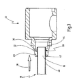
- das Optikrohr und den Endoskopkopf in Fig. 2 in einem weiteren Verfahrensschritt des Herstellungsverfahrens;
- Fig. 4
- den Endoskopkopf und das Optikrohr in Fig. 3 mit einem Verpresswerkzeug in einem weiteren Verfahrensschritt des Herstellungsverfahrens;
- Fig. 5
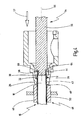
- den Endoskopkopf und das Optikrohr sowie das Verpresswerkzeug in Fig. 4 in einem weiteren Verfahrensstadium des Herstellungsverfahrens;
- Fig. 6
- den Endoskopkopf, das Optikrohr und das Verpresswerkzeug in Fig. 5 in einem weiteren Verfahrensstadium des Herstellungsverfahrens;
- Fig. 7
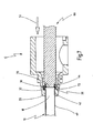
- den Endoskopkopf und das Optikrohr in Fig. 6 und ein weiteres Verpresswerkzeug in einem weiteren Verfahrensstadium des Herstellungsverfahrens;
- Fig. 8
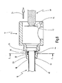
- den Endoskopkopf, das Optikrohr und das weitere Verpresswerkzeug in Fig. 7 in einem weiteren Verfahrensschritt des Herstellungsverfahrens; und
- Fig. 9
- den Endoskopkopf in einem Querschnitt entlang der Linie I-I in Fig. 8.
- In Fig. 1 ist ein mit dem allgemeinen Bezugszeichen 10 versehenes Endoskop dargestellt. Das Endoskop 10 weist einen Endoskopkopf 12 und einen Endoskopschaft 14 auf.
- Ein derartiges Endoskop 10 wird bspw. in der minimal-invasiven Chirurgie zur Untersuchung von Körperhohlräumen oder Hohlorganen verwendet. Hierbei wird das Endoskop 10 distalseitig in eine Körperöffnung eingeführt, so dass zumindest der Endoskopkopf 12 außerhalb des Körpers verbleibt.
- Der Endoskopschaft 14 weist ein langerstrecktes Optikrohr 16 auf, dessen proximaler Endbereich 18 mit einem distalen Endbereich 20 des Endoskopkopfs 12 verbunden ist. Das Optikrohr 16 ist vorzugsweise als zylinderförmiger Hohlzylinder mit geringer Wandstärke ausgebildet.
- Am Endoskopkopf 12 sind ein Anschluss 22 für eine externe Beleuchtungsquelle und eine Augenmuschel 24 angeordnet. Im Endoskop 10 ist ferner ein Lichtleitsystem aufgenommen, das sich ausgehend von dem Anschluss 22 zu einem distalen Endbereich 26 des Optikrohrs 16 erstreckt und aus Lichtleitfasern gefertigt ist. Das Lichtleitsystem wird zur Beleuchtung eines Operationsgebietes innerhalb der Körperöffnung verwendet. Ferner ist in dem Endoskop 10 ein Bildgebungssystem aufgenommen, das sich von der Augenmuschel 24 bis zu dem distalen Endbereich 26 des Optikrohrs 16 erstreckt. Das Bildgebungssystem kann Lichtleitfasern, Stablinsen oder auch einen Bildsensor mit elektrischer Signalübertragung aufweisen.
- Das Endoskop 10 ist vorzugsweise starr ausgebildet, wobei das Optikrohr 16 aus nicht biegsamen Materialien, wie beispielsweise Stahl oder Metall, gefertigt ist.
- Bei einem Verfahren zum Herstellen des Endoskops 10 wird in einem ersten Verfahrensschritt das Optikrohr 16 sowie der Endoskopkopf 12 bereitgestellt (siehe Fig. 2). Der Endoskopkopf 12 weist innenseitig an seinem distalen Endbereich 20 einen umfänglichen Einstich 28 sowie zumindest eine umfänglich begrenzte Ausbuchtung 30 auf.
- Der Einstich 28 ist vorzugsweise als vollumfängliche Nut 32 in dem distalen Endbereich 20 des Endoskopkopfs 12 ausgebildet. Die Ausbuchtung 30 kann entweder direkt an einem Teil des Einstichs 28 angeordnet oder von diesem räumlich beabstandet in dem distalen Endbereich 20 des Endoskopkopfs 12 ausgebildet sein. Ferner kann die Ausbuchtung 30 in radialer Richtung des distalen Endbereichs 20 des Endoskopkopfs 12 gesehen gegenüber dem Einstich 28 vertieft sein.
- Ein Außendurchmesser 34 des Optikrohrs 16 ist derart bemessen, dass er geringfügig kleiner als ein Innendurchmesser 36 des distalen Endbereichs 20 des Endoskopkopfs 12 ist.
- Wie in Fig. 3 dargestellt, wird in einem weiteren Verfahrensschritt der proximale Endbereich 18 des Optikrohrs 16 entlang einer Richtung eines Pfeils 38 in den distalen Endbereich 20 des Endoskopkopfs 12 eingeschoben. Hierbei berührt eine Außenfläche 40 des Optikrohrs 16 eine Innenfläche 42 des Endoskopkopfs 12 oder die Außenfläche 40 des Optikrohrs 16 ist geringfügig beabstandet zu der Innenfläche 42 des distalen Endbereichs 20 des Endoskopfkopfs 12. Ferner wird der proximale Endbereich 18 des Optikrohrs 16 so weit in den distalen Endbereich 20 des Endoskopkopfs 12 eingeschoben, dass zumindest ein proximales Ende 44 des Optikrohrs 16 über den Einstich 28 und die Ausbuchtung 30 hinausreicht.
- Fig. 4-8 zeigen das Verpressen des distalen Endbereichs 20 des Endoskopkopfs 12 mit dem proximalen Endbereich 18 des Optikrohrs 16.
- Das Optikrohr 16, dessen proximaler Endbereich 18 in dem distalen Endbereich 20 des Endoskopkopfs 12 eingeschoben ist, wird axial lagefest gegenüber Zug- und Druckkräften, die in axialer Richtung des Optikrohrs 16 weisen, gehalten (siehe Fig. 4). Hierzu wird das Optikrohr 16 in eine Haltevorrichtung 46 eingespannt. Solch eine Haltevorrichtung 46 kann bspw. zwei Backen 48, 50 aufweisen, die an der Außenfläche 40 des eingeschobenen Optikrohrs 16 distalseitig des distalen Endbereichs 20 des Endoskopkopfs 12 angreifen. Die beiden Backen 48, 50 berühren entweder den distalen Endbereich 20 des Endoskopkopfs 12 oder sie sind zu diesem geringfügig beabstandet. Die Backen 48, 50 der Haltevorrichtung 46 sind in Fig. 4 dargestellt, während sie übersichtshalber in Fig. 5-8 nicht gezeigt sind.
- Es wird in Richtung eines Pfeils 52 eine axiale Kraft auf den proximalen Endbereich 18 des Optikrohrs 16 ausgeübt, Die axiale Kraft wird mittels eines Verpresswerkzeugs 54 erzeugt, das proximalseitig durch den Endoskopkopf 12 in das Optikrohr 16 eingeführt wird.
- Das Verpresswerkzeug 54 kann vorzugsweie als zylinderförmiger Dorn 56 ausgebildet sein. Das Verpresswerkzeug 54 verjüngt sich an einem distalen Ende 58 stufenförmig, so dass ein Außendurchmesser 60 des distalen Endes 58 des Verpresswerkzeugs 54 geringfügig kleiner als ein Innendurchmesser 62 des Optikrohrs 16 ausgebildet ist. Ferner weist das Verpresswerkzeug 54 im Bereich der stufenförmigen Verjüngung eine vorzugsweise vollumfängliche Planfläche 64 auf, die quer zu einer Längsachse 66 des Verpresswerkzeugs 54 ausgebildet ist, an der das proximale Ende 44 des Optikrohrs 16 vollumfänglich zur Anlage kommt. Vorzugsweise ist das distale Ende 58 des Verpresswerkzeugs 54 derart lang ausgebildet, dass das Verpresswerkzeug 54 in einem vollständig eingeschobenen Zustand, d.h. wenn die Planfläche 64 das proximale Ende 44 des Optikrohrs 16 berührt, über den Einstich 28 und die Ausbuchtung 30 reicht.
- Wie in Fig. 5 dargestellt, wird der proximale Endbereich 18 des Optikrohrs 16 derart durch die axiale Kraft gestaucht, dass gestauchtes Material radial nach außen verschoben wird. Dies ist insbesondere der Fall, wenn das distale Ende 58 des Verpresswerkzeugs 54 über den Einstich 28 und die Ausbuchtung 30 reicht und somit ein radial nach innen gerichtetes Verschieben des gestauchten Materials verhindert, Hierbei greift Material des proximalen Endbereichs 18 des Optikrohrs 16 formschlüssig in den Einstich 28 ein, während das Optikrohr 16 mit dem Endoskopkopf 12 verpresst wird. Das Eingreifen des Materials des Optikrohrs 16 in den Einstich 28 ermöglicht eine sichere axiale Lagefixierung des Optikrohrs 16 bezüglich des Endoskopkopfs 12.
- Durch das Verpressen greift ferner Material des Optikrohrs 16 in die Ausbuchtung 30 ein (siehe Fig. 6). Hierdurch wird verhindert, dass sich das Optikrohr 16 relativ zum Endoskopkopf 12 um seine Längsachse verdrehen kann.
- Wie in Fig. 7 dargestellt, wird zusätzlich das proximale Ende 44 des Optikrohrs 16 trompetenartig aufgeweitet, so dass sich der Außendurchmesser 34 des Optikrohrs 16 an dieser Stelle vergrößert. Das proximale Ende 44 des Optikrohrs 16 weist von einer Längsachse des Optikrohrs 16 aus gesehen nach außen weg. Hierzu wird das Verpresswerkzeug 54 aus dem Optikrohr 16 und dem Endoskopkopf 12 entnommen. Es wird ein weiteres Verpresswerkzeug 68 in Richtung des Pfeils 52 durch den Endoskopkopf 12 in das verpresste Optikrohr 16 eingeschoben, mit dem eine axiale Kraft auf den proximalen Endbereich 18 des Optikrohrs 16 erzeugt wird.
- Das weitere Verpresswerkzeug 68 verjüngt sich ebenfalls distalseitig, wobei die Verjüngung nicht stufenförmig ausgebildet ist, sondern sich über einen konkav gekrümmten Teilbereich eines distalen Endes 70 erstreckt. Ein kleinster Außendurchmesser 72 des distalen Endes 70 des weiteren Verpresswerkzeugs 68 ist ebenfalls geringfügig kleiner als der Innendurchmesser 62 des Optikrohrs 16 ausgebildet. Das sich verjüngende distale Ende 70 des weiteren Verpresswerkzeugs 68 dehnt das proximale Ende 44 des Optikrohrs 16 derart aus, dass sich eine Form des proximalen Endes 44 des Optikrohrs 16 einer Form des distalen Endes 70 des weiteren Verpresswerkzeugs 68 anpasst. Das Verpresswerkzeug 54 und das Verpresswerkzeug 68 können auch als ein Verpresswerkzeug ausgebildet sein, mit dem der proximale Endbereich 18 des Optikrohrs 16 sowohl gestaucht als auch das proximale Ende 44 des Optikrohrs 16 aufgeweitet werden kann.
- Das aufgeweitete proximale Ende 44 des Optikrohrs 16 verhindert bei einem späteren Einführen von Lichtleitfasern in das Endoskop 10 eine Beschädigung letzterer.
- Danach wird das weitere Verpresswerkzeug 68 in Richtung eines Pfeils 74 aus dem Endoskopkopf 12 entnommen (siehe Fig. 8).
- Der proximale Endbereich 18 des Optikrohrs 16 wird nach dem Verpressen ferner mit dem distalen Endbereich 20 des Endoskopkopfs 12 verklebt. Hierzu wird ein Klebstoff auf die Außenfläche 40 des Optikrohrs 16 und/oder auf die Innenfläche 42 des distalen Endbereichs 20 des Endoskopkopfs 12 aufgebracht- Das Verkleben des Optikrohrs 16 mit dem Endoskopkopf 12 dient zur Abdichtung der Verbindungsstelle beider Endoskopteile gegenüber äußeren Einflüssen, wie bspw. Wasser.
- Fig. 9 zeigt eine Querschnittszeichnung des distalen Endbereichs 20 des Endoskopkopfs 12 entlang der Linie I-I in Fig. 8. Der proximale Endbereich 18 des Optikrohrs 16 ist mit dem distalen Endbereich 20 des Endoskopkopfs 12 verpresst. Material des Optikrohrs 16 greift formschlüssig in den als vollumfängliche Nut 32 ausgebildeten Einstich 28 und in die Ausbuchtung 30 ein.
Claims (14)
- Verfahren zum Herstellen eines Endoskops (10), wobei das Endoskop (10) einen Endoskopkopf (12) und ein Optikrohr (16) aufweist, mit den Schritten- Bereitstellen des Endoskopkopfs (12),- Bereitstellen des Optikrohrs (16),- Einschieben eines proximalen Endbereichs (18) des Optikrohrs (16) in einen distalen Endbereich (20) des Endoskopkopfs (12),dadurch gekennzeichnet, dass der distale Endbereich (20) des Endoskopkopfs (12) mit dem proximalen Endbereich (18) des Optikrohrs (16) verpresst wird.
- Verfahren nach Anspruch 1, dadurch gekennzeichnet, dass der proximale Endbereich (18) des Optikrohrs (16) durch Stauchen verpresst wird.
- Verfahren nach Anspruch 1 oder 2, dadurch gekennzeichnet, dass das Optikrohr (16) beim Verpressen axial lagefest gehalten wird und eine axiale Kraft in Richtung eines distalen Endbereichs (26) des Optikrohrs (16) auf den proximalen Endbereich (18) des Optikrohrs (16) ausgeübt wird.
- Verfahren nach Anspruch 3, dadurch gekennzeichnet, dass die axiale Kraft durch ein Verpresswerkzeug (54), insbesondere einen Dorn (56), bereitgestellt wird.
- Verfahren nach einem der Ansprüche 1 bis 4, dadurch gekennzeichnet, dass der distale Endbereich (20) des Endoskopkopfs (12) innenseitig mit einem umfänglichen Einstich (28) bereitgestellt wird, in den beim Verpressen Material des Optikrohrs (16) formschlüssig einfließt.
- Verfahren nach Anspruch 5, dadurch gekennzeichnet, dass der umfängliche Einstich (28) als vollumfängliche Nut (32) bereitgestellt wird.
- Verfahren nach einem der Ansprüche 1 bis 6, dadurch gekennzeichnet, dass der distale Endbereich (20) des Endoskopkopfs (12) mit zumindest einer umfänglich begrenzten Ausbuchtung (30) bereitgestellt wird, in die beim Verpressen Material des Optikrohrs (16) formschlüssig einfließt.
- Verfahren nach einem der Ansprüche 1 bis 7, dadurch gekennzeichnet, dass zusätzlich ein proximales Ende (44) des Optikrohrs (16) trompetenartig aufgeweitet wird.
- Verfahren nach einem der Ansprüche 1 bis 8, dadurch gekennzeichnet, dass der distale Endbereich (20) des Endoskopkopfs (12) nach dem Verpressen mit dem proximalen Endbereich (18) des Optikrohrs (16) verklebt wird.
- Endoskop, mit einem Endoskopkopf (12) und einem Optikrohr (16), dadurch gekennzeichnet, dass ein proximaler Endbereich (18) des Optikrohrs (16) mit einem distalen Endbereich (20) des Endoskopkopfs (12) verpresst ist.
- Endoskop nach Anspruch 10, dadurch gekennzeichnet, dass der distale Endbereich (20) des Endoskopkopfs (12) innenseitig einen umfänglichen Einstich (28) aufweist, in den Material des Optikrohrs (16) formschlüssig eingreift.
- Endoskop nach Anspruch 11, dadurch gekennzeichnet, dass der umfängliche Einstich (24) als vollumfängliche Nut (32) ausgebildet ist.
- Endoskop nach einem der Ansprüche 10 bis 12, dadurch gekennzeichnet, dass der distale Endbereich (20) des Endoskopkopfs (12) innenseitig zumindest eine umfänglich begrenzte Ausbuchtung (30) aufweist, in die Material des Optikrohrs (16) formschlüssig eingreift.
- Endoskop nach einem der Ansprüche 10 bis 13, dadurch gekennzeichnet, dass ein proximales Ende (44) des Optikrohrs (16) trompetenartig aufgeweitet ist.
Applications Claiming Priority (1)
| Application Number | Priority Date | Filing Date | Title |
|---|---|---|---|
| DE102006030521A DE102006030521A1 (de) | 2006-07-01 | 2006-07-01 | Verfahren zum Herstellen eines Endoskops sowie derartiges Endoskop |
Publications (2)
| Publication Number | Publication Date |
|---|---|
| EP1872706A1 true EP1872706A1 (de) | 2008-01-02 |
| EP1872706B1 EP1872706B1 (de) | 2012-09-12 |
Family
ID=38608767
Family Applications (1)
| Application Number | Title | Priority Date | Filing Date |
|---|---|---|---|
| EP07012791A Active EP1872706B1 (de) | 2006-07-01 | 2007-06-29 | Verfahren zum Herstellen eines Endoskops sowie derartiges Endoskop |
Country Status (3)
| Country | Link |
|---|---|
| US (2) | US20080097160A1 (de) |
| EP (1) | EP1872706B1 (de) |
| DE (1) | DE102006030521A1 (de) |
Cited By (1)
| Publication number | Priority date | Publication date | Assignee | Title |
|---|---|---|---|---|
| EP3363345A1 (de) * | 2017-02-17 | 2018-08-22 | Karl Storz SE & Co. KG | Endoskop, endoskopkopf sowie verfahren zum herstellen eines endoskops |
Families Citing this family (3)
| Publication number | Priority date | Publication date | Assignee | Title |
|---|---|---|---|---|
| DE102010002334A1 (de) * | 2010-02-25 | 2011-08-25 | Henke-Sass, Wolf GmbH, 78532 | Endoskop |
| DE102016201905A1 (de) * | 2016-02-09 | 2017-08-10 | Olympus Winter & Ibe Gmbh | Chirurgisches Instrument und Verfahren zum Herstellen eines chirurgischen Instruments |
| FR3163547A1 (fr) | 2024-06-20 | 2025-12-26 | Assistance Publique Hopitaux De Paris | Dispositif médical d’endoscopie comprenant un tube rigide |
Citations (6)
| Publication number | Priority date | Publication date | Assignee | Title |
|---|---|---|---|---|
| US2621651A (en) | 1949-06-02 | 1952-12-16 | American Cystoscope Makers Inc | Instrument for dilating and examining the esophagus |
| US4237871A (en) | 1978-09-20 | 1980-12-09 | Richard Wolf Gmbh | Devices for injecting pastes or fluids into the human body |
| JPS5897439A (ja) * | 1981-12-02 | 1983-06-09 | Hitachi Ltd | 金属板に金属賀を固着する方法 |
| US5341566A (en) * | 1993-05-10 | 1994-08-30 | Eaton Corporation | Conduit attachment |
| DE19713275A1 (de) | 1997-03-29 | 1998-10-01 | Storz Karl Gmbh & Co | Endoskop mit Längenausgleich bei thermischer Belastung |
| US20060069307A1 (en) | 2004-09-30 | 2006-03-30 | Scimed Life Systems, Inc. | Selectively rotatable shaft coupler |
Family Cites Families (14)
| Publication number | Priority date | Publication date | Assignee | Title |
|---|---|---|---|---|
| DE7338410U (de) * | 1974-05-09 | Gebrueder Uhl Kg | Rohr mit Verbindungsvorrichtung | |
| JPS55138434A (en) * | 1979-04-17 | 1980-10-29 | Olympus Optical Co | Hard endoscope |
| US4732139A (en) * | 1985-09-03 | 1988-03-22 | Olympus Optical Co., Ltd. | Endoscope with insertion having a plurality of insertion holes |
| US4779613A (en) * | 1986-03-13 | 1988-10-25 | Olympus Optical Co., Ltd. | Endoscope with means for preventing an observing optical system from being fogged |
| US5575757A (en) * | 1992-10-09 | 1996-11-19 | Smith & Nephew Endoscopy Inc. | Endoscope with focusing mechanism |
| US5408992A (en) * | 1993-11-05 | 1995-04-25 | British Technology Group Usa Inc. | Endoscopic device for intraoral use |
| US5634881A (en) * | 1995-10-20 | 1997-06-03 | United States Surgical Corporation | Laparoscope |
| DE19841155C1 (de) | 1998-09-09 | 2000-01-05 | Mertik Maxitrol Gmbh & Co Kg | Rohrverbindung zum gasdichten Anschluß an ein Mehrschichtverbundrohr |
| US20020133058A1 (en) * | 2000-09-26 | 2002-09-19 | Calderwood Mitchell C. | Prophylactic cover and drape for endoscopic camera system |
| JP3639561B2 (ja) * | 2002-04-08 | 2005-04-20 | オリンパス株式会社 | 内視鏡用フード |
| JP2006242299A (ja) * | 2005-03-03 | 2006-09-14 | Denso Corp | 継手部付き管部材およびその製造方法 |
| JP2006322609A (ja) * | 2005-04-21 | 2006-11-30 | Denso Corp | パイプの固定構造およびパイプの固定方法 |
| US7658708B2 (en) * | 2005-09-20 | 2010-02-09 | Ai Medical Devices, Inc. | Endotracheal intubation device |
| JP5897493B2 (ja) | 2013-03-28 | 2016-03-30 | 株式会社クボタ | 農作業データの通信システム |
-
2006
- 2006-07-01 DE DE102006030521A patent/DE102006030521A1/de not_active Withdrawn
-
2007
- 2007-06-29 EP EP07012791A patent/EP1872706B1/de active Active
- 2007-06-29 US US11/770,855 patent/US20080097160A1/en not_active Abandoned
-
2017
- 2017-04-07 US US15/481,772 patent/US11141042B2/en active Active
Patent Citations (6)
| Publication number | Priority date | Publication date | Assignee | Title |
|---|---|---|---|---|
| US2621651A (en) | 1949-06-02 | 1952-12-16 | American Cystoscope Makers Inc | Instrument for dilating and examining the esophagus |
| US4237871A (en) | 1978-09-20 | 1980-12-09 | Richard Wolf Gmbh | Devices for injecting pastes or fluids into the human body |
| JPS5897439A (ja) * | 1981-12-02 | 1983-06-09 | Hitachi Ltd | 金属板に金属賀を固着する方法 |
| US5341566A (en) * | 1993-05-10 | 1994-08-30 | Eaton Corporation | Conduit attachment |
| DE19713275A1 (de) | 1997-03-29 | 1998-10-01 | Storz Karl Gmbh & Co | Endoskop mit Längenausgleich bei thermischer Belastung |
| US20060069307A1 (en) | 2004-09-30 | 2006-03-30 | Scimed Life Systems, Inc. | Selectively rotatable shaft coupler |
Cited By (2)
| Publication number | Priority date | Publication date | Assignee | Title |
|---|---|---|---|---|
| EP3363345A1 (de) * | 2017-02-17 | 2018-08-22 | Karl Storz SE & Co. KG | Endoskop, endoskopkopf sowie verfahren zum herstellen eines endoskops |
| DE102017103267A1 (de) | 2017-02-17 | 2018-08-23 | Karl Storz Se & Co. Kg | Endoskop, Endoskopkopf sowie Verfahren zum Herstellen eines Endoskops |
Also Published As
| Publication number | Publication date |
|---|---|
| US20080097160A1 (en) | 2008-04-24 |
| US11141042B2 (en) | 2021-10-12 |
| EP1872706B1 (de) | 2012-09-12 |
| DE102006030521A1 (de) | 2008-01-03 |
| US20170209021A1 (en) | 2017-07-27 |
Similar Documents
| Publication | Publication Date | Title |
|---|---|---|
| EP1596703B1 (de) | Verfahren zum montieren eines endoskopes | |
| DE10004869B4 (de) | Verbindungsanordnung für ein Endoskop oder ein Behandlungsinstrument sowie ein Verfahren zum Herstellen derselben | |
| EP1776918B1 (de) | Endoskop und Verfahren zu seiner Herstellung | |
| DE19510962C2 (de) | Medizinisch-endoskopisches Gerät mit superelastischem Element | |
| EP2770361A1 (de) | Optikrohr für ein Endoskop, Endoskop sowie Verfahren zum Montieren mindestens einer Stablinse in einem Optikrohr | |
| EP1872706B1 (de) | Verfahren zum Herstellen eines Endoskops sowie derartiges Endoskop | |
| DE4441373C2 (de) | Rohrverbindung, insbesondere für Rohre mit mindestens einer Kunststoffschicht | |
| EP3363345B1 (de) | Endoskop, endoskopkopf sowie verfahren zum herstellen eines endoskops | |
| EP2853187A1 (de) | Herstellen eines Endoskops mit einer Lichtleiteinrichtung | |
| EP2002166B1 (de) | Verbindungsanordnung | |
| EP2653117B1 (de) | Kupplung zwischen zwei Teilen eines medizinischen Instruments | |
| EP2446980B1 (de) | Gerüstrohr und Verfahren zur Bearbeitung von Rohrenden | |
| EP3305168B1 (de) | Endoskop und verfahren zum fixieren eines bündels von lichtleitern in einem schaft eines endoskops | |
| DE102009037317A1 (de) | Vorrichtung und Verfahren zur Zentrierung von Innen- und Außenrohr eines Endoskops | |
| EP3300675B1 (de) | Komponente für ein medizinisches instrument und medizinisches instrument | |
| WO2017137357A1 (de) | Chirurgisches instrument und verfahren zum herstellen eines chirurgischen instruments | |
| DE19706766B4 (de) | Befestigungsverfahren | |
| DE29818534U1 (de) | Verbindung für Rohr- und/oder Schlauchleitungen | |
| EP1664609B1 (de) | Metallschlauch und verfahren zur herstellung eines metallschlauchs | |
| DE2932107C2 (de) | Elektrisch isolierende Verbindung zur Kupplung rohrförmiger Endteile | |
| DE102019109921A1 (de) | Verfahren zur Schaffung einer Pressverbindungsanordnung, Pressverbindungsanordnung und Verfahren zur Schaffung einer Spannverbindung sowie die Spannverbindung an sich sowie deren Verwendung | |
| WO2006084766A1 (de) | Verbindungsanordnung | |
| WO2018028961A1 (de) | Verfahren zur herstellung einer rohranordnung für ein medizinisches endoskop, rohranordnung und medizinisches endoskop | |
| EP4492579A1 (de) | Verfahren zur herstellung eines zusammenbaus eines steckverbinders und eines koaxialkabels sowie zusammenbau | |
| DE102024115712A1 (de) | Rohrverbindung und Rohrverbinder |
Legal Events
| Date | Code | Title | Description |
|---|---|---|---|
| PUAI | Public reference made under article 153(3) epc to a published international application that has entered the european phase |
Free format text: ORIGINAL CODE: 0009012 |
|
| AK | Designated contracting states |
Kind code of ref document: A1 Designated state(s): AT BE BG CH CY CZ DE DK EE ES FI FR GB GR HU IE IS IT LI LT LU LV MC MT NL PL PT RO SE SI SK TR |
|
| AX | Request for extension of the european patent |
Extension state: AL BA HR MK YU |
|
| 17P | Request for examination filed |
Effective date: 20080619 |
|
| 17Q | First examination report despatched |
Effective date: 20080730 |
|
| AKX | Designation fees paid |
Designated state(s): DE FR GB IT |
|
| GRAP | Despatch of communication of intention to grant a patent |
Free format text: ORIGINAL CODE: EPIDOSNIGR1 |
|
| GRAS | Grant fee paid |
Free format text: ORIGINAL CODE: EPIDOSNIGR3 |
|
| GRAA | (expected) grant |
Free format text: ORIGINAL CODE: 0009210 |
|
| AK | Designated contracting states |
Kind code of ref document: B1 Designated state(s): DE FR GB IT |
|
| REG | Reference to a national code |
Ref country code: GB Ref legal event code: FG4D Free format text: NOT ENGLISH |
|
| REG | Reference to a national code |
Ref country code: DE Ref legal event code: R096 Ref document number: 502007010524 Country of ref document: DE Effective date: 20121031 |
|
| PLBE | No opposition filed within time limit |
Free format text: ORIGINAL CODE: 0009261 |
|
| STAA | Information on the status of an ep patent application or granted ep patent |
Free format text: STATUS: NO OPPOSITION FILED WITHIN TIME LIMIT |
|
| 26N | No opposition filed |
Effective date: 20130613 |
|
| REG | Reference to a national code |
Ref country code: DE Ref legal event code: R097 Ref document number: 502007010524 Country of ref document: DE Effective date: 20130613 |
|
| REG | Reference to a national code |
Ref country code: FR Ref legal event code: PLFP Year of fee payment: 10 |
|
| REG | Reference to a national code |
Ref country code: FR Ref legal event code: PLFP Year of fee payment: 11 |
|
| REG | Reference to a national code |
Ref country code: DE Ref legal event code: R081 Ref document number: 502007010524 Country of ref document: DE Owner name: KARL STORZ SE & CO. KG INTELLECTUAL PROPERTY, DE Free format text: FORMER OWNER: KARL STORZ GMBH & CO. KG, 78532 TUTTLINGEN, DE Ref country code: DE Ref legal event code: R082 Ref document number: 502007010524 Country of ref document: DE Representative=s name: WITTE, WELLER & PARTNER PATENTANWAELTE MBB, DE Ref country code: DE Ref legal event code: R081 Ref document number: 502007010524 Country of ref document: DE Owner name: KARL STORZ SE & CO. KG, DE Free format text: FORMER OWNER: KARL STORZ GMBH & CO. KG, 78532 TUTTLINGEN, DE |
|
| REG | Reference to a national code |
Ref country code: FR Ref legal event code: PLFP Year of fee payment: 12 |
|
| P01 | Opt-out of the competence of the unified patent court (upc) registered |
Effective date: 20230527 |
|
| PGFP | Annual fee paid to national office [announced via postgrant information from national office to epo] |
Ref country code: DE Payment date: 20250626 Year of fee payment: 19 |
|
| PGFP | Annual fee paid to national office [announced via postgrant information from national office to epo] |
Ref country code: GB Payment date: 20250618 Year of fee payment: 19 |
|
| PGFP | Annual fee paid to national office [announced via postgrant information from national office to epo] |
Ref country code: FR Payment date: 20250624 Year of fee payment: 19 |
|
| PGFP | Annual fee paid to national office [announced via postgrant information from national office to epo] |
Ref country code: IT Payment date: 20250623 Year of fee payment: 19 |