EP1870271A1 - Roller blind for a vehicle window - Google Patents
Roller blind for a vehicle window Download PDFInfo
- Publication number
- EP1870271A1 EP1870271A1 EP07011998A EP07011998A EP1870271A1 EP 1870271 A1 EP1870271 A1 EP 1870271A1 EP 07011998 A EP07011998 A EP 07011998A EP 07011998 A EP07011998 A EP 07011998A EP 1870271 A1 EP1870271 A1 EP 1870271A1
- Authority
- EP
- European Patent Office
- Prior art keywords
- roller
- roller blind
- shaft
- window
- springs
- Prior art date
- Legal status (The legal status is an assumption and is not a legal conclusion. Google has not performed a legal analysis and makes no representation as to the accuracy of the status listed.)
- Granted
Links
Images


Classifications
-
- B—PERFORMING OPERATIONS; TRANSPORTING
- B60—VEHICLES IN GENERAL
- B60J—WINDOWS, WINDSCREENS, NON-FIXED ROOFS, DOORS, OR SIMILAR DEVICES FOR VEHICLES; REMOVABLE EXTERNAL PROTECTIVE COVERINGS SPECIALLY ADAPTED FOR VEHICLES
- B60J1/00—Windows; Windscreens; Accessories therefor
- B60J1/20—Accessories, e.g. wind deflectors, blinds
- B60J1/2011—Blinds; curtains or screens reducing heat or light intensity
- B60J1/2013—Roller blinds
- B60J1/2019—Roller blinds powered, e.g. by electric, hydraulic or pneumatic actuators
- B60J1/2025—Roller blinds powered, e.g. by electric, hydraulic or pneumatic actuators with flexible actuating elements connected to the draw bar for pulling only, e.g. cords, wires or cables
-
- B—PERFORMING OPERATIONS; TRANSPORTING
- B60—VEHICLES IN GENERAL
- B60J—WINDOWS, WINDSCREENS, NON-FIXED ROOFS, DOORS, OR SIMILAR DEVICES FOR VEHICLES; REMOVABLE EXTERNAL PROTECTIVE COVERINGS SPECIALLY ADAPTED FOR VEHICLES
- B60J1/00—Windows; Windscreens; Accessories therefor
- B60J1/20—Accessories, e.g. wind deflectors, blinds
- B60J1/2011—Blinds; curtains or screens reducing heat or light intensity
- B60J1/2013—Roller blinds
- B60J1/2033—Roller blinds characterised by the spring motor
-
- B—PERFORMING OPERATIONS; TRANSPORTING
- B60—VEHICLES IN GENERAL
- B60J—WINDOWS, WINDSCREENS, NON-FIXED ROOFS, DOORS, OR SIMILAR DEVICES FOR VEHICLES; REMOVABLE EXTERNAL PROTECTIVE COVERINGS SPECIALLY ADAPTED FOR VEHICLES
- B60J1/00—Windows; Windscreens; Accessories therefor
- B60J1/20—Accessories, e.g. wind deflectors, blinds
- B60J1/2011—Blinds; curtains or screens reducing heat or light intensity
- B60J1/2013—Roller blinds
- B60J1/2036—Roller blinds characterised by structural elements
- B60J1/2058—Springs for compensating the number of windings of the blind on the tube in case winding tube and draw bar are driven together
-
- B—PERFORMING OPERATIONS; TRANSPORTING
- B60—VEHICLES IN GENERAL
- B60J—WINDOWS, WINDSCREENS, NON-FIXED ROOFS, DOORS, OR SIMILAR DEVICES FOR VEHICLES; REMOVABLE EXTERNAL PROTECTIVE COVERINGS SPECIALLY ADAPTED FOR VEHICLES
- B60J1/00—Windows; Windscreens; Accessories therefor
- B60J1/20—Accessories, e.g. wind deflectors, blinds
- B60J1/2011—Blinds; curtains or screens reducing heat or light intensity
- B60J1/2013—Roller blinds
- B60J1/2066—Arrangement of blinds in vehicles
- B60J1/2075—Arrangement of blinds in vehicles specially adapted for fixed windows
-
- B—PERFORMING OPERATIONS; TRANSPORTING
- B60—VEHICLES IN GENERAL
- B60J—WINDOWS, WINDSCREENS, NON-FIXED ROOFS, DOORS, OR SIMILAR DEVICES FOR VEHICLES; REMOVABLE EXTERNAL PROTECTIVE COVERINGS SPECIALLY ADAPTED FOR VEHICLES
- B60J1/00—Windows; Windscreens; Accessories therefor
- B60J1/20—Accessories, e.g. wind deflectors, blinds
- B60J1/2011—Blinds; curtains or screens reducing heat or light intensity
- B60J1/2013—Roller blinds
- B60J1/2066—Arrangement of blinds in vehicles
- B60J1/2086—Arrangement of blinds in vehicles specially adapted for openable windows, e.g. side window
Definitions
- the invention relates to a window roller blind for a vehicle window according to the preamble of claim 1.
- Such a window blind is off EP 1 645 448 A1 known.
- the well-known window blind has a roller blind on which a roller blind up and can be unwound.
- a pull-out roller blind end which can be in the form of an extension rod.
- the cables are connected to the two ends of the extension rod or the extendable roller blind end and pulleys of the cables are coaxial with the roller shaft and rotatably mounted relative to the roller shaft.
- a resilient compensation device is provided for a tightening of the roller blind during the winding and unwinding.
- the object of the invention is to provide a window blind of the type mentioned, in which the drive forces supplied by the drive means are transmitted evenly to the roller blind during the winding and unwinding of the roller blind.
- each spring is provided between each of the two pulleys and the roller blind.
- the two springs which are arranged at both ends of the roller blind shaft, exert during the unwinding of the roller blind on the extendable roller blind pull-out forces, wherein they are supported on the driven and driven by the drive means in the tape extension direction roller blind shaft.
- the two springs are preferably designed as spiral or roller springs whose inner spring ends are connected to the roller shaft and whose outer spring end with the pulleys.
- the pull-out forces exerted by the springs on the rope pulleys are transmitted via elongate tension elements, for example tension cables or tension straps or the like, to the extendable roller blind end with which the tension elements are connected.
- elongate tension elements for example tension cables or tension straps or the like
- this one Zaelementenden with the extendable roller blind end and the other Glaselementenden connected to the pulleys, wherein the elongate tension elements over pulleys, which are arranged in the vicinity of the upper window boundary, are performed.
- roller shaft drive shaft parts At both ends of the roller shaft drive shaft parts may be provided, which are rotatably connected to the roller shaft.
- the pulleys and the springs can be arranged on these drive shaft parts, wherein the pulleys are rotatably mounted relative to these drive shaft parts.
- the drive shaft parts can be formed by a one-piece drive shaft protruding through the preferably hollow roller shaft, which projects beyond the two roller blind ends.
- This drive shaft or the drive shaft parts have for rotationally fixed connection to the roller shaft at least in the region of the roller shaft a deviating from the circular cross-section and have on the peripheral surface axially extending teeth or ribs.
- the pulleys are within a certain angular range, which is smaller than 360 ° and preferably can be about 180 °, compared rotatably mounted roller blind.
- the pull-out force is transmitted to the extendable roller blind when unwinding the roller blind from the roller shaft, wherein, as already explained, the springs acting in this case are supported against the roller shaft driven by the drive device or against the drive shaft splitter rotatably connected to the roller shaft.
- This predetermined angular range can be determined by stops, which are rotatably connected to the pulley and the roller shaft.
- the roller shaft When winding up the roller blind, the roller shaft is rotated by the drive means in the direction opposite to the extension direction (winding), wherein the corresponding retraction force, which is generated by the drive means, is transmitted from the roller shaft to the roller blind.
- the springs in particular spiral or roller springs is brought within the specified angular range to the desired bias relative to the roller shaft.
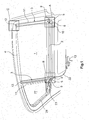
- the exemplary embodiments for a window roller blind illustrated in FIGS. 1 and 2 are suitable for covering a lateral vehicle window on the vehicle interior.
- the respective embodiment has a roller blind 1, which can be wound up and unwound on a roller shaft 2.
- the driving force is supplied for this purpose by a drive device 13, which may be preferably designed as an electric motor, in particular a DC motor.
- the drive device can be driven in two drive directions of rotation in order to drive the roller shaft 2 during winding and unwinding of the roller blind 1 in two opposite directions of rotation.
- roller blind 1 of the roller shaft 2 When unwinding the roller blind 1 of the roller shaft 2, this is rotated in the direction of the pull-out of the roller blind in the unwinding. The roller blind 1 is released for a pull-out.
- roller shaft 2 pulleys 5 are rotatably mounted relative to the roller shaft 2 and coaxial with the roller shaft 2.
- the storage takes place in the illustrated embodiments on rotatably connected to the roller shaft 2 drive shaft parts 9.
- These drive shaft parts 9 can be formed by a guided through the hollow roller shaft 2 one-piece drive shaft.
- the drive shaft is rotatably connected by their deviating from the circular cross-sectional shape shape with the roller shaft 2.
- longitudinally extending teeth or ribs on the circumference of the drive shaft or the drive shaft parts 9 may be provided at least in the region of the roller shaft 2.
- elongate tension members 11 which may be formed as cables, bands or the like, connected.
- the tension elements 11, 11 are formed so that they can be wound onto the pulleys 5 and unwound from the pulleys 5.
- the other ends of the tension elements 5 are, as will be explained in detail, with the two ends (right and left) in Figs. 1 and 2 of an extendable and preferably rigidly formed roller blind end 4, which may be formed as a pull-out rod in a known manner, connected.
- deflection rollers 12 which lie in the vicinity of the upper window boundary.
- the tension elements 11, the guide rollers 12 and the pulleys 5 form cables, which are provided at both ends of the roller shaft 2 and extend in the vertical direction along guide paths for the roller blind 1 during winding and unwinding.
- the axes of rotation of the pulleys 5 and the guide rollers 12 are arranged perpendicular to each other and in the embodiment of Fig. 2, the axes of the pulleys 5 and the guide rollers 12 are arranged parallel to each other.
- Fig. 6 the connection between the tension member 11 and the pull-out designed as a pull-out roller blind end 4 is shown in detail.
- the end of the tension member 11 is connected in an attachment point 21 with a carriage 19 which is guided in a carriage guide 20 substantially vertically along the movement path during winding and unwinding of the blind sheet 1.
- the extendable roller blind end 4 is preferably articulated and optionally resiliently connected. This arrangement is located on both sides of the extendable roller blind end 4.
- the springs 6 are supported on the rotating roller shaft 2 and exert the torques required for winding the tension elements 11 onto the pulleys 5.
- the springs 6 are formed as spiral or roller springs.
- Inner spring ends 7 are rotatably connected to the roller shaft 2. This can be done via the drive shaft parts 6, as shown in the illustrated embodiments.
- the inner spring ends 7 are firmly connected to the drive shaft parts 9.
- Outer spring ends 8 of the springs 6 are connected to the pulleys 5. This is done in the illustrated embodiments via spring housing 10, with which the pulleys 5 are rotatably connected.
- the springs 6 are arranged in the interior of the spring housing 10.
- roller shaft 2 When winding the roller blind 1 on the roller shaft 2, the roller shaft 2 is rotated by the drive device 13 in the opposite direction, i. Roller blind feed direction turned. In this case, a pull-in force is exerted on the blind sheet 1 in the winding direction via the roller shaft 2. This force is transmitted via the tension elements 11 on the pulleys 5 during unwinding of the tension elements 11 of the pulleys 5. Due to the speed difference between the roller shaft 2 and the pulleys 5, the springs 6 are tensioned. In this way, the springs 6 are brought into the desired state for a renewed roller blind extract.
- the drive device 13 can be brought into rotational drive connection with the roller shaft 2 in various ways. In the embodiment of FIG. 1, this is done by means of an elongate push / pull element 22, which as a brush cable, flexible toothed belt, flexible perforated belt or the like can be trained.
- the push / pull element 22 is flexible transversely to its direction of movement and rigid in the direction of movement.
- the longitudinal movement of the push / pull element 22 is converted by means of a gear 23, which may be formed as a bevel gear or worm gear, in a rotational movement of the drive shaft or the drive shaft parts 9 and thus the roller shaft 2.
- the roller shaft 2 can be moved during the winding and unwinding of the roller blind 1 in the direction of its shaft axis. By this axial displacement different widths of the roller blind during winding and unwinding can be compensated. Such axial displaceability is out DE 20 2004 000 631 U1 known.
- a vehicle-fixed spindle 16 is provided for the axial displaceability of the roller shaft, in the outer thread engages a rotationally fixed at the end of the roller shaft 2 arranged threaded engagement member 26.
- the threaded engagement piece 26 rotates together with the roller shaft 2. As a result, a controlled axial movement of the roller shaft 2 is achieved.
- a movable with the axial movement of the roller shaft 2 stop 18 may be provided on the roller blind end, which abuts against a stop fixed to the vehicle 18 to limit the extension length of the blind sheet 2. This extension length depends on the height of the vehicle window to be covered.
- the roller shaft 2 is returned to its original position.
- the right drive shaft part 9 extends through the vehicle-fixed spindle 16 and carries at the outer right end of the rotatably mounted pulley 5 with the associated spring 6, soft, as already explained, as a spiral or scroll spring in rotation with the pulley 5 connected spring housing 10 is arranged (Fig. 4).
- a stop 14 and the drive shaft part 9, a stop 15 are provided on the spring housing 10, a stop 14 and the drive shaft part 9, a stop 15 are provided.
- these two stops of the rotation angle range within which the spring housing 10th and the rotatably connected pulley 5 relative to the drive shaft part 9 and thus against the roller shaft 2 can rotate limited.
- the stops 14 and 15 of this rotation angle range is limited to a range of less than 360 °. In the illustrated embodiment, this rotation angle range is approximately 180 °. Other rotation angle ranges within> 0 ° and ⁇ 360 ° can also be selected.
- stops 14 and 15 ensures that occurring during the winding or unwinding of the roller blind along the guide lines movement resistance, for example, by tilting or foreign bodies acting on the roller shaft 2 drive force can be transmitted directly to the pulley 5.
- the drive movement of the push / pull element 22 can also be utilized for actuating a triangular window roller blind 27.
- the drive movement of the push / pull element 22 is transmitted to a pivotable pullout lever 28, as it is made DE 299 21 860 U1 is known.
Landscapes
- Engineering & Computer Science (AREA)
- Mechanical Engineering (AREA)
- Operating, Guiding And Securing Of Roll- Type Closing Members (AREA)
Abstract
Description
Die Erfindung betrifft ein Fensterrollo für ein Fahrzeugfenster gemäß dem Oberbegriff des Patentanspruches 1.The invention relates to a window roller blind for a vehicle window according to the preamble of
Ein derartiges Fensterrollo ist aus
Aufgabe der Erfindung ist es, ein Fensterrollo der eingangs genannten Art zu schaffen, bei welchem die von der Antriebseinrichtung gelieferten Antriebskräfte während des Auf- und Abwickelns der Rollobahn gleichmäßig auf die Rollobahn übertragen werden.The object of the invention is to provide a window blind of the type mentioned, in which the drive forces supplied by the drive means are transmitted evenly to the roller blind during the winding and unwinding of the roller blind.
Diese Aufgabe wird erfindungsgemäß durch die Merkmale des Patentanspruches 1 gelöst. In den neuen Unteransprüchen sind vorteilhafte Weiterbildungen der Erfindung angegeben.This object is achieved by the features of
Bei der Erfindung ist zwischen jeder der beiden Seilrollen und der Rollowelle jeweils eine im aufgewickelten Zustand der Rollobahn gespannte Feder vorgesehen. Die beiden Federn, welche an beiden Enden der Rollowelle angeordnet sind, üben beim Abwickeln der Rollobahn auf das ausziehbare Rollobahnende Auszugskräfte aus, wobei sie sich an der von der Antriebseinrichtung in Bandauszugsrichtung angetriebenen und gedrehten Rollowelle abstützen. Hierzu sind die beiden Federn vorzugsweise als Spiral- oder Rollfedern ausgebildet, deren innere Federenden mit der Rollowelle und deren äußere Federende mit den Seilrollen verbunden sind. Die von den Federn auf die Seilrollen ausgeübten Auszugskräfte werden über längliche Zugelemente, beispielsweise Zugseile oder Zugbänder oder dergleichen, auf das ausziehbare Rollobahnende, mit welchem die Zugelemente verbunden sind, übertragen. Vorzugsweise sind hierzu die einen Zugelementenden mit dem ausziehbaren Rollobahnende und die anderen Zugelementenden mit den Seilrollen verbunden, wobei die länglichen Zugelemente über Umlenkrollen, die in der Nähe der oberen Fensterbegrenzung angeordnet sind, geführt werden.In the invention, a tensioned in the wound state of the roller blind each spring is provided between each of the two pulleys and the roller blind. The two springs, which are arranged at both ends of the roller blind shaft, exert during the unwinding of the roller blind on the extendable roller blind pull-out forces, wherein they are supported on the driven and driven by the drive means in the tape extension direction roller blind shaft. For this purpose, the two springs are preferably designed as spiral or roller springs whose inner spring ends are connected to the roller shaft and whose outer spring end with the pulleys. The pull-out forces exerted by the springs on the rope pulleys are transmitted via elongate tension elements, for example tension cables or tension straps or the like, to the extendable roller blind end with which the tension elements are connected. Preferably, this one Zugelementenden with the extendable roller blind end and the other Zugelementenden connected to the pulleys, wherein the elongate tension elements over pulleys, which are arranged in the vicinity of the upper window boundary, are performed.
An beiden Enden der Rollowelle können Antriebswellenteile vorgesehen sein, welche drehfest mit der Rollowelle verbunden sind. Die Seilrollen und die Federn können an diesen Antriebswellenteilen angeordnet sein, wobei die Seilrollen drehbar gegenüber diesen Antriebswellenteilen gelagert sind.At both ends of the roller shaft drive shaft parts may be provided, which are rotatably connected to the roller shaft. The pulleys and the springs can be arranged on these drive shaft parts, wherein the pulleys are rotatably mounted relative to these drive shaft parts.
Die Antriebswellenteilen können von einer durch die vorzugsweise hohl ausgebildete Rollowelle ragenden einstückigen Antriebswelle, welche an den beiden Rollowellenenden übersteht, gebildet werden. Diese Antriebswelle bzw. die Antriebswellenteile besitzen zur drehfesten Verbindung mit der Rollowelle zumindest im Bereich der Rollowelle einen von der Kreisform abweichenden Querschnitt und weisen an der Umfangsfläche axial verlaufende Zähne oder Rippen auf.The drive shaft parts can be formed by a one-piece drive shaft protruding through the preferably hollow roller shaft, which projects beyond the two roller blind ends. This drive shaft or the drive shaft parts have for rotationally fixed connection to the roller shaft at least in the region of the roller shaft a deviating from the circular cross-section and have on the peripheral surface axially extending teeth or ribs.
In bevorzugter Weise sind die Seilrollen innerhalb eines bestimmten Winkelbereiches, der kleiner als 360° ist und vorzugsweise etwa 180° betragen kann, gegenüber der Rollowelle drehbar gelagert. Innerhalb dieses Winkelbereiches wird beim Abwickeln der Rollobahn von der Rollowelle die Auszugskraft auf das ausziehbare Rolloende übertragen, wobei, wie schon erläutert, sich die hierbei wirkenden Federn gegenüber der von der Antriebseinrichtung angetriebenen Rollowelle oder gegenüber den drehfest mit der Rollowelle verbundenen Antriebswellenteiler abstützen. Dieser vorbestimmte Winkelbereich kann durch Anschläge bestimmt werden, welche drehfest mit der Seilrolle und der Rollowelle verbunden sind. Hierzu können die Anschläge an wenigstens einem der Federgehäuse, welche drehfest mit den Seilrollen verbunden sind, und an einem der Antriebswellenteile vorgesehen sein. Hierdurch ist ferner gewährleistet, dass die auf die Rollowelle wirkende Antriebskraft unmittelbar auf die Seilrollen übertragen wird, wenn bei der Auszugsbewegung ein Widerstand auftritt.Preferably, the pulleys are within a certain angular range, which is smaller than 360 ° and preferably can be about 180 °, compared rotatably mounted roller blind. Within this angular range, the pull-out force is transmitted to the extendable roller blind when unwinding the roller blind from the roller shaft, wherein, as already explained, the springs acting in this case are supported against the roller shaft driven by the drive device or against the drive shaft splitter rotatably connected to the roller shaft. This predetermined angular range can be determined by stops, which are rotatably connected to the pulley and the roller shaft. For this purpose, the stops on at least one of the spring housing, which are rotatably connected to the pulleys, and be provided on one of the drive shaft parts. This also ensures that the force acting on the roller shaft driving force is transmitted directly to the pulleys, when a resistance occurs during the extension movement.
Durch die Erfindung wird eine geräuscharme und Toleranzen entlang der Bewegungsstrecken zu beiden Seiten der Rollobahn ausgleichende Führung beim Aufund Abwickeln der Rollobahn erreicht.By the invention, a quiet and tolerances along the movement paths on both sides of the roller blind compensating guidance when winding and unwinding of the roller blind is achieved.
Beim Aufwickeln der Rollobahn wird die Rollowelle von der Antriebseinrichtung in der zur Auszugsrichtung entgegengesetzten Richtung (Aufwickelrichtung) gedreht, wobei die entsprechende Einzugskraft, welche von der Antriebseinrichtung erzeugt wird, von der Rollowelle auf die Rollobahn übertragen wird. Bei dieser Einzugsbewegung werden die über die Umlenkrolle geführten länglichen Zugelemente von den Seilrollen abgewickelt, wobei die Federn, insbesondere Spiral- oder Rollfedern innerhalb des bestimmten Winkelbereiches auf die gewünschte Vorspannung gegenüber der Rollowelle gebracht wird.When winding up the roller blind, the roller shaft is rotated by the drive means in the direction opposite to the extension direction (winding), wherein the corresponding retraction force, which is generated by the drive means, is transmitted from the roller shaft to the roller blind. In this retraction movement over the guide roller guided elongated tension elements are unwound from the pulleys, the springs, in particular spiral or roller springs is brought within the specified angular range to the desired bias relative to the roller shaft.
Anhand der Figuren wird an Ausführungsbeispielen die Erfindung noch näher erläutert.Based on the figures, the invention will be explained in more detail by embodiments.
Es zeigt
- Fig. 1
- ein erstes Ausführungsbeispiel in Seitenansicht;
- Fig. 2
- in schematischer Darstellung wesentliche Bestandteile eines zweiten Ausführungsbeispiels;
- Fig. 3
- eine Detaildarstellung im in Fig. 1 mit A bezeichneten Bereich am rechten Ende der Rollowelle;
- Fig. 4
- eine weitere Detaildarstellung im mit A umrandeten Bereich in Fig. 1;
- Fig. 5
- eine Detaildarstellung im mit B in Fig. 1 bezeichneten Bereich am linken Ende der Rollowelle; und
- Fig. 6
- eine Detaildarstellung im mit C in Fig. 1 bezeichneten Bereich am oberen Seilzugende.
- Fig. 1
- a first embodiment in side view;
- Fig. 2
- a schematic representation of essential components of a second embodiment;
- Fig. 3
- a detailed representation in the designated in Figure 1 with A region at the right end of the roller blind shaft.
- Fig. 4
- a further detailed representation in the area bordered by A in FIG. 1;
- Fig. 5
- a detailed representation in the designated B in Figure 1 area at the left end of the roller blind shaft. and
- Fig. 6
- a detailed representation in the designated C in Fig. 1 area at the upper cable end.
Die in den Fig. 1 und 2 dargestellten Ausführungsbeispiele für ein Fensterrollo sind dazu geeignet, ein seitliches Fahrzeugfenster an der Fahrzeuginnenseite abzudecken. Hierzu weist das jeweilige Ausführungsbeispiel eine Rollobahn 1 auf, die auf einer Rollowelle 2 auf- und abgewickelt werden kann. Die Antriebskraft wird hierfür von einer Antriebseinrichtung 13 geliefert, welche vorzugsweise als Elektromotor, insbesondere Gleichstrommotor ausgebildet sein kann. Die Antriebseinrichtung kann in zwei Antriebsdrehrichtungen angetrieben werden, um die Rollowelle 2 beim Auf- und Abwickeln der Rollobahn 1 in zwei entgegengesetzten Drehrichtungen anzutreiben.The exemplary embodiments for a window roller blind illustrated in FIGS. 1 and 2 are suitable for covering a lateral vehicle window on the vehicle interior. For this purpose, the respective embodiment has a roller blind 1, which can be wound up and unwound on a
Beim Abwickeln der Rollobahn 1 von der Rollowelle 2 wird diese im Sinne der Ausziehbewegung der Rollobahn in Abwickelrichtung gedreht. Dabei wird die Rollobahn 1 für eine Ausziehbewegung freigegeben.When unwinding the roller blind 1 of the
An den beiden Enden der Rollowelle 2 sind Seilrollen 5 gegenüber der Rollowelle 2 drehbar und koaxial zur Rollowelle 2 gelagert. Die Lagerung erfolgt bei den dargestellten Ausführungsbeispielen auf drehfest mit der Rollowelle 2 verbundenen Antriebswellenteilen 9. Diese Antriebswellenteile 9 können von einer durch die hohl ausgebildete Rollowelle 2 hindurchgeführten einteiligen Antriebswelle gebildet werden. Die Antriebswelle ist durch ihre von der kreisrunden Querschnittsform abweichenden Form drehfest mit der Rollowelle 2 verbunden. Hierzu können längsverlaufende Zähne oder Rippen am Umfang der Antriebswelle bzw. den Antriebswellenteilen 9 zumindest im Bereich der Rollowelle 2 vorgesehen sein.At the two ends of the
Mit den beiden Seilrollen 5, welche drehbar auf den Antriebswellenteilen 9 gelagert sind, sind eine Enden von länglichen Zugelementen 11, welche als Seile, Bänder oder dergleichen ausgebildet sein können, verbunden. Die Zugelemente, 11 sind so ausgebildet, dass sie auf die Seilrollen 5 aufgewickelt und von den Seilrollen 5 abgewickelt werden können. Die anderen Enden der Zugelemente 5 sind, wie im einzelnen noch erläutert wird, mit den beiden Enden (rechts und links) in den Fig. 1 und 2 eines ausziehbaren und vorzugsweise starr ausgebildeten Rollobahnendes 4, das als Auszugsstab in bekannter Weise ausgebildet sein kann, verbunden. Zwischen den beiden Enden werden die Zugelemente 11 über Umlenkrollen 12 geführt, welche in der Nähe der oberen Fensterbegrenzung liegen. Die Zugelemente 11, die Umlenkrollen 12 und die Seilrollen 5 bilden Seilzüge, welche an beiden Enden der Rollowelle 2 vorgesehen sind und sich in vertikaler Richtung entlang von Führungsstrecken für die Rollobahn 1 beim Aufund Abwickeln erstrecken. Beim Ausführungsbeispiel der Fig. 1 sind die Drehachsen der Seilrollen 5 und der Umlenkrollen 12 senkrecht zueinander angeordnet und beim Ausführungsbeispiel der Fig. 2 sind die Achsen der Seilrollen 5 und der Umlenkrollen 12 parallel zueinander angeordnet.With the two
In Fig. 6 ist im einzelnen die Verbindung zwischen dem Zugelement 11 und dem als Auszugsstab ausgebildeten ausziehbaren Rollobahnende 4 dargestellt. Hierzu ist das Ende des Zugelements 11 in einer Befestigungsstelle 21 mit einem Schlitten 19 verbunden, der in einer Schlittenführung 20 im wesentlichen vertikal entlang der Bewegungsstrecke beim Auf- und Abrollen der Rollobahn 1 geführt ist. Mit dem Schlitten 19 ist das ausziehbare Rollobahnende 4 vorzugsweise gelenkig und gegebenenfalls federnd nachgiebig verbunden. Diese Anordnung befindet sich an beiden Seiten des ausziehbaren Rollobahnendes 4.In Fig. 6 the connection between the
Zwischen jeder der beiden Seilrollen 5 und der Rollowelle 2 ist jeweils eine Feder 6 vorgesehen, welche im aufgewickelten Zustand der Rollobahn 1 gespannt ist. Beim Ausziehen der Rollobahn 1 in die in der Fig. 1 dargestellte ausgezogene Position wird die Rollowelle 2 von der Antriebseinrichtung 13 mit entsprechender Drehrichtung angetrieben. Hierdurch wird die Rollobahn 1 für eine Auszugsbewegung in die in Fig. 1 dargestellte Position freigegeben. Aufgrund der Vorspannkraft, welche von den beiden Federn 6 an beiden Enden der Rollowelle 2 gebildet ist, wird auf die beiden Seilrollen 5 ein Drehmoment übertragen, mit welchem im Zuge der Freigabe der Rollobahn 1 von der sich drehenden Rollowelle 2 die Zugelemente 11 auf die Seilrollen 5 aufgewickelt werden. Hierdurch werden über die um die Umlenkrollen 12 geführten Zugelemente 11 auf das ausziehbare Rollobahnende 4 Ausziehkräfte ausgeübt und das Rollobahnende 4 wird von der Rollowelle 2 wegbewegt.Between each of the two
Die Federvorspannung wirkt dabei zwischen der sich im Sinne der Rollobahnauszugsrichtung drehenden Rollowelle 2 und den Seilrollen 5. Bei den dargestellten Ausführungsbeispielen sind die Federn 6 an der sich drehenden Rollowelle 2 abgestützt und üben die zum Aufwickeln der Zugelemente 11 auf die Seilrollen 5 erforderlichen Drehmomente aus.In this case, the
Bei den dargestellten Ausführungsbeispielen sind die Federn 6 als Spiral- oder Rollfedern ausgebildet. Innere Federenden 7 sind drehfest mit der Rollowelle 2 verbunden. Dies kann, wie in den dargestellten Ausführungsbeispielen gezeigt ist, über die Antriebswellenteile 6 erfolgen. Hierzu sind die inneren Federenden 7 fest mit den Antriebswellenteilen 9 verbunden. Äußere Federenden 8 der Federn 6 sind mit den Seilrollen 5 verbunden. Dies erfolgt bei den dargestellten Ausführungsbeispielen über Federgehäuse 10, mit denen die Seilrollen 5 drehfest verbunden sind. Die Federn 6 sind im Innern der Federgehäuse 10 angeordnet.In the illustrated embodiments, the
Beim Aufwickeln der Rollobahn 1 auf die Rollowelle 2 wird die Rollowelle 2 von der Antriebseinrichtung 13 in entgegengesetzter Richtung, d.h. Rollobahn-Einzugsrichtung gedreht. Dabei wird über die Rollowelle 2 auf die Rollobahn 1 in Aufwickelrichtung eine Einzugskraft ausgeübt. Diese Kraft wird über die Zugelemente 11 auf die Seilrollen 5 beim Abwickeln der Zugelemente 11 von den Seilrollen 5 übertragen. Aufgrund des Drehzahlunterschieds zwischen der Rollowelle 2 und den Seilrollen 5 werden die Federn 6 gespannt. Auf diese Weise werden die Federn 6 in den für einen erneuten Rollobahnauszug gewünschten Zustand gebracht.When winding the
Die Antriebseinrichtung 13 kann auf verschiedene Art und Weise in Drehantriebsverbindung mit der Rollowelle 2 gebracht werden. Beim Ausführungsbeispiel der Fig. 1 erfolgt dies mittels eines länglichen Schub-/Zugelements 22, welches als Bürstenkabel, flexibler Zahnriemen, flexibles gelochtes Band oder dergleichen ausgebildet sein kann. Das Schub-/Zugelement 22 ist quer zu seiner Bewegungsrichtung flexibel und in Bewegungsrichtung starr ausgebildet. Die Längsbewegung des Schub-/Zugelements 22 wird mit Hilfe eines Getriebes 23, welches als Kegelradgetriebe oder Schneckenradgetriebe ausgebildet sein kann, in eine Drehbewegung der Antriebswelle bzw. der Antriebswellenteile 9 und damit der Rollowelle 2 gewandelt.The
Bei dem in Fig. 2 dargestellten Ausführungsbeispiel wird mit Hilfe eines Schneckenradgetriebes 24 die Antriebsdrehbewegung einer Ausgangswelle 25 der Antriebseinrichtung 13 auf das in Fig. 2 rechts angeordnete Antriebswellenteil 9 und damit auf die Rollowelle 2 übertragen.In the embodiment shown in FIG. 2, the drive rotational movement of an
Die Rollowelle 2 kann während des Auf- und Abwickelns der Rollobahn 1 in Richtung ihrer Wellenachse verschoben werden. Durch diese axiale Verschiebung können unterschiedliche Breiten der Rollobahn beim Auf- und Abwickeln ausgeglichen werden. Eine derartige axiale Verschiebbarkeit ist aus
Aus Fig. 5 ist zu ersehen, dass am Federgehäuse 10 ein Anschlag 14 und am Antriebswellenteil 9 ein Anschlag 15 vorgesehen sind. Durch diese beiden Anschläge wird der Drehwinkelbereich, innerhalb welchem das Federgehäuse 10 und die drehfest damit verbundene Seilrolle 5 gegenüber dem Antriebswellenteil 9 und damit gegenüber der Rollowelle 2 sich verdrehen können, begrenzt. Durch entsprechende Anordnung der Anschläge 14 und 15 wird dieser Drehwinkelbereich auf einen Bereich von geringer als 360° begrenzt. Beim dargestellten Ausführungsbeispiel beträgt dieser Drehwinkelbereich ca. 180°. Es können auch andere Drehwinkelbereiche innerhalb > 0° und < 360° ausgewählt werden. Durch die Anschläge 14 und 15 ist gewährleistet, dass bei einem während des Auf- oder Abwickelns der Rollobahn entlang der Führungsstrecken auftretenden Bewegungswiederstand beispielsweise durch Verkanten oder Fremdkörper, die auf die Rollowelle 2 wirkende Antriebkraft direkt auch auf die Seilrolle 5 übertragen werden kann.From Fig. 5 it can be seen that on the
Bei dem in Fig. 1 dargestellten Ausführungsbeispiel kann die Antriebsbewegung des Schub-/Zugelementes 22 auch zur Betätigung eines Dreieckfenster-Rollos 27 ausgenutzt werden. Hierzu wird die Antriebsbewegung des Schub-/Zugelementes 22 auf einen schwenkbaren Ausziehhebel 28 übertragen, wie es aus
- 11
- Rollobahnblind web
- 22
- Rollowelleblind shaft
- 33
- Seilzügecables
- 44
- ausziehbares Rollobahnenderetractable roller blind end
- 55
- Seilrollenpulleys
- 66
- Federn (Spiral- oder Rollfedern)Springs (spiral or roller springs)
- 77
- innere Federendeninner spring ends
- 88th
- äußere Federendenouter spring ends
- 99
- AntriebswellenteileDrive shaft parts
- 1010
- Federgehäusespring housing
- 1111
- Zugelement (Seil, Band)Tension element (rope, strap)
- 1212
- Umlenkrolleidler pulley
- 1313
- Antriebseinrichtungdriving means
- 1414
- Anschlagattack
- 1515
- Anschlagattack
- 1616
- fahrzeugfeste Spindelvehicle-mounted spindle
- 1717
- fahrzeugfester Anschlagvehicle-resistant stop
- 1818
- axial verschiebbarer Anschlagaxially displaceable stop
- 1919
- Schlittencarriage
- 2020
- Schlittenführungcarriage guide
- 2121
- Befestigungsstellefastening point
- 2222
- Schub-/ZugelementPush / pull element
- 2323
- Getriebetransmission
- 2424
- Schneckenradgetriebeworm gear
- 2525
- Ausgangswelleoutput shaft
- 2626
- GewindeeingriffsteilThread engaging portion
- 2727
- Dreieckfenster-RolloTriangular window blind
- 2828
- Ausziehhebelextractor lever
Claims (14)
Applications Claiming Priority (1)
| Application Number | Priority Date | Filing Date | Title |
|---|---|---|---|
| DE200610028351 DE102006028351A1 (en) | 2006-06-20 | 2006-06-20 | Window roller blind for a vehicle window |
Publications (2)
| Publication Number | Publication Date |
|---|---|
| EP1870271A1 true EP1870271A1 (en) | 2007-12-26 |
| EP1870271B1 EP1870271B1 (en) | 2012-01-18 |
Family
ID=38331405
Family Applications (1)
| Application Number | Title | Priority Date | Filing Date |
|---|---|---|---|
| EP20070011998 Active EP1870271B1 (en) | 2006-06-20 | 2007-06-19 | Roller blind for a vehicle window |
Country Status (2)
| Country | Link |
|---|---|
| EP (1) | EP1870271B1 (en) |
| DE (1) | DE102006028351A1 (en) |
Cited By (2)
| Publication number | Priority date | Publication date | Assignee | Title |
|---|---|---|---|---|
| EP3081415A1 (en) * | 2015-04-14 | 2016-10-19 | BOS GmbH & Co. KG | Protective device for a motor vehicle |
| DE102016208676A1 (en) | 2016-05-19 | 2017-11-23 | Bos Gmbh & Co. Kg | Shading device for a vehicle interior |
Families Citing this family (1)
| Publication number | Priority date | Publication date | Assignee | Title |
|---|---|---|---|---|
| DE202012000995U1 (en) | 2012-01-31 | 2012-04-24 | Lisa Dräxlmaier GmbH | Roller blind with tensioning device |
Citations (4)
| Publication number | Priority date | Publication date | Assignee | Title |
|---|---|---|---|---|
| EP1319772A1 (en) * | 2001-12-14 | 2003-06-18 | MHZ SONNENSCHUTZTECHNIK GmbH | Positive return awning with one sided length compensating device |
| DE202004000631U1 (en) | 2004-01-16 | 2004-03-18 | Hs Products Engineering Gmbh | Vehicle window blind |
| EP1626152A1 (en) * | 2004-08-09 | 2006-02-15 | BOS GmbH & Co. KG | Solar protection device for glass roof |
| EP1645448A1 (en) | 2004-10-08 | 2006-04-12 | HS Products Engineering GmbH | Window roller blind for a vehicle window |
-
2006
- 2006-06-20 DE DE200610028351 patent/DE102006028351A1/en not_active Withdrawn
-
2007
- 2007-06-19 EP EP20070011998 patent/EP1870271B1/en active Active
Patent Citations (4)
| Publication number | Priority date | Publication date | Assignee | Title |
|---|---|---|---|---|
| EP1319772A1 (en) * | 2001-12-14 | 2003-06-18 | MHZ SONNENSCHUTZTECHNIK GmbH | Positive return awning with one sided length compensating device |
| DE202004000631U1 (en) | 2004-01-16 | 2004-03-18 | Hs Products Engineering Gmbh | Vehicle window blind |
| EP1626152A1 (en) * | 2004-08-09 | 2006-02-15 | BOS GmbH & Co. KG | Solar protection device for glass roof |
| EP1645448A1 (en) | 2004-10-08 | 2006-04-12 | HS Products Engineering GmbH | Window roller blind for a vehicle window |
Cited By (5)
| Publication number | Priority date | Publication date | Assignee | Title |
|---|---|---|---|---|
| EP3081415A1 (en) * | 2015-04-14 | 2016-10-19 | BOS GmbH & Co. KG | Protective device for a motor vehicle |
| DE102015206661A1 (en) * | 2015-04-14 | 2016-10-20 | Bos Gmbh & Co. Kg | Protective device for a motor vehicle |
| DE102015206661B4 (en) | 2015-04-14 | 2022-02-24 | Bos Gmbh & Co. Kg | Protective device for a motor vehicle |
| DE102016208676A1 (en) | 2016-05-19 | 2017-11-23 | Bos Gmbh & Co. Kg | Shading device for a vehicle interior |
| WO2017198376A1 (en) | 2016-05-19 | 2017-11-23 | Bos Gmbh & Co. Kg | Shading device for a vehicle interior |
Also Published As
| Publication number | Publication date |
|---|---|
| EP1870271B1 (en) | 2012-01-18 |
| DE102006028351A1 (en) | 2007-12-27 |
Similar Documents
| Publication | Publication Date | Title |
|---|---|---|
| EP1645448B1 (en) | Window roller blind for a vehicle window | |
| EP1905630B1 (en) | Manually operated window roller blind | |
| WO2006012856A1 (en) | Roller blind system | |
| DE102006046069A1 (en) | Manually actuatable roll-up window shade for motor vehicle, has two drive gears arranged at ends of wind-up shaft, where each drive gear is allocated to respective one of push elements | |
| EP3266631B1 (en) | Shading device for a pane of a motor vehicle | |
| DE19834777C2 (en) | Roller blind, in particular sun protection roller blind for the transparent roof window of a motor vehicle | |
| EP1872989B1 (en) | Roller blind for a vehicle window | |
| EP1211113A2 (en) | Driving device for vehicle sliding roof | |
| DE202006003901U1 (en) | Sliding door arrangement e.g. for motor vehicle, has sliding door which is adjustable by sliding movement into opened position and into closed position | |
| EP1870271B1 (en) | Roller blind for a vehicle window | |
| DE102008031467A1 (en) | Adjusting device i.e. cable-controlled window lifter, for adjusting window pane of frame less vehicle door in motor vehicle, has drive unit reducing length of rope loop of mechanism in phase of adjusting process of adjustment part | |
| DE19539848C2 (en) | Roller blind, in particular for motor vehicles | |
| DE102017218895B4 (en) | Protective device for an interior of a motor vehicle | |
| DE10206161B4 (en) | Openable vehicle roof with at least one lid and two covering devices | |
| WO2006063565A1 (en) | Blind for a vehicle window | |
| EP0529591B1 (en) | Roller blind, preferably for vehicle rear windows | |
| DE202006017838U1 (en) | Window e.g. rear window, blind, for e.g. passenger car, has two guide rails, and two drive gears that are positioned in extension of guide rails for drive of blind and respectively attached to push units | |
| DE202004020106U1 (en) | Window roller blind for motor vehicle window, has sliding units connected with section that is detachable from winding shaft and with drive device over drive section, and drive adjustment device for modifying length of drive section | |
| EP1319772A1 (en) | Positive return awning with one sided length compensating device | |
| DE202006017842U1 (en) | Window blind for motor vehicles has guide rail on each side of material web, two band-form operating components allocated to respective guide rails, and two drive pinions each allocated to respective operating component | |
| DE3700546C2 (en) | ||
| WO2011086084A1 (en) | Roller blind device | |
| EP1878600B1 (en) | Roller blind for a motor vehicle side window | |
| EP3781422A1 (en) | Roller blind device for a vehicle window | |
| DE102016001400A1 (en) | Roller blind for a motor vehicle, in particular a passenger car |
Legal Events
| Date | Code | Title | Description |
|---|---|---|---|
| PUAI | Public reference made under article 153(3) epc to a published international application that has entered the european phase |
Free format text: ORIGINAL CODE: 0009012 |
|
| AK | Designated contracting states |
Kind code of ref document: A1 Designated state(s): AT BE BG CH CY CZ DE DK EE ES FI FR GB GR HU IE IS IT LI LT LU LV MC MT NL PL PT RO SE SI SK TR |
|
| AX | Request for extension of the european patent |
Extension state: AL BA HR MK YU |
|
| RIN1 | Information on inventor provided before grant (corrected) |
Inventor name: ZIEGENBEIN, WERNER |
|
| 17P | Request for examination filed |
Effective date: 20080508 |
|
| AKX | Designation fees paid |
Designated state(s): DE FR GB IT |
|
| GRAP | Despatch of communication of intention to grant a patent |
Free format text: ORIGINAL CODE: EPIDOSNIGR1 |
|
| GRAS | Grant fee paid |
Free format text: ORIGINAL CODE: EPIDOSNIGR3 |
|
| GRAA | (expected) grant |
Free format text: ORIGINAL CODE: 0009210 |
|
| AK | Designated contracting states |
Kind code of ref document: B1 Designated state(s): DE FR GB IT |
|
| REG | Reference to a national code |
Ref country code: GB Ref legal event code: FG4D Free format text: NOT ENGLISH |
|
| REG | Reference to a national code |
Ref country code: DE Ref legal event code: R096 Ref document number: 502007009095 Country of ref document: DE Effective date: 20120322 |
|
| PLBE | No opposition filed within time limit |
Free format text: ORIGINAL CODE: 0009261 |
|
| STAA | Information on the status of an ep patent application or granted ep patent |
Free format text: STATUS: NO OPPOSITION FILED WITHIN TIME LIMIT |
|
| 26N | No opposition filed |
Effective date: 20121019 |
|
| REG | Reference to a national code |
Ref country code: DE Ref legal event code: R097 Ref document number: 502007009095 Country of ref document: DE Effective date: 20121019 |
|
| REG | Reference to a national code |
Ref country code: FR Ref legal event code: PLFP Year of fee payment: 10 |
|
| REG | Reference to a national code |
Ref country code: FR Ref legal event code: PLFP Year of fee payment: 11 |
|
| REG | Reference to a national code |
Ref country code: FR Ref legal event code: PLFP Year of fee payment: 12 |
|
| PGFP | Annual fee paid to national office [announced via postgrant information from national office to epo] |
Ref country code: IT Payment date: 20190619 Year of fee payment: 13 |
|
| PGFP | Annual fee paid to national office [announced via postgrant information from national office to epo] |
Ref country code: FR Payment date: 20190626 Year of fee payment: 13 |
|
| PGFP | Annual fee paid to national office [announced via postgrant information from national office to epo] |
Ref country code: GB Payment date: 20190624 Year of fee payment: 13 |
|
| GBPC | Gb: european patent ceased through non-payment of renewal fee |
Effective date: 20200619 |
|
| PG25 | Lapsed in a contracting state [announced via postgrant information from national office to epo] |
Ref country code: GB Free format text: LAPSE BECAUSE OF NON-PAYMENT OF DUE FEES Effective date: 20200619 Ref country code: FR Free format text: LAPSE BECAUSE OF NON-PAYMENT OF DUE FEES Effective date: 20200630 |
|
| PG25 | Lapsed in a contracting state [announced via postgrant information from national office to epo] |
Ref country code: IT Free format text: LAPSE BECAUSE OF NON-PAYMENT OF DUE FEES Effective date: 20200619 |
|
| REG | Reference to a national code |
Ref country code: DE Ref legal event code: R082 Ref document number: 502007009095 Country of ref document: DE Representative=s name: MATHYS & SQUIRE EUROPE PATENTANWAELTE PARTNERS, DE |
|
| PGFP | Annual fee paid to national office [announced via postgrant information from national office to epo] |
Ref country code: DE Payment date: 20230623 Year of fee payment: 17 |