EP1868710B1 - Agitating device and method for sewage treatment - Google Patents
Agitating device and method for sewage treatment Download PDFInfo
- Publication number
- EP1868710B1 EP1868710B1 EP06724030A EP06724030A EP1868710B1 EP 1868710 B1 EP1868710 B1 EP 1868710B1 EP 06724030 A EP06724030 A EP 06724030A EP 06724030 A EP06724030 A EP 06724030A EP 1868710 B1 EP1868710 B1 EP 1868710B1
- Authority
- EP
- European Patent Office
- Prior art keywords
- ribs
- agitating device
- agitating
- basin
- shaft
- Prior art date
- Legal status (The legal status is an assumption and is not a legal conclusion. Google has not performed a legal analysis and makes no representation as to the accuracy of the status listed.)
- Active
Links
Images


Classifications
-
- C—CHEMISTRY; METALLURGY
- C02—TREATMENT OF WATER, WASTE WATER, SEWAGE, OR SLUDGE
- C02F—TREATMENT OF WATER, WASTE WATER, SEWAGE, OR SLUDGE
- C02F3/00—Biological treatment of water, waste water, or sewage
- C02F3/02—Aerobic processes
- C02F3/12—Activated sludge processes
- C02F3/1278—Provisions for mixing or aeration of the mixed liquor
- C02F3/1284—Mixing devices
-
- B—PERFORMING OPERATIONS; TRANSPORTING
- B01—PHYSICAL OR CHEMICAL PROCESSES OR APPARATUS IN GENERAL
- B01F—MIXING, e.g. DISSOLVING, EMULSIFYING OR DISPERSING
- B01F23/00—Mixing according to the phases to be mixed, e.g. dispersing or emulsifying
- B01F23/20—Mixing gases with liquids
- B01F23/23—Mixing gases with liquids by introducing gases into liquid media, e.g. for producing aerated liquids
- B01F23/234—Surface aerating
- B01F23/2342—Surface aerating with stirrers near to the liquid surface, e.g. partially immersed, for spraying the liquid in the gas or for sucking gas into the liquid, e.g. using stirrers rotating around a horizontal axis or using centrifugal force
- B01F23/23421—Surface aerating with stirrers near to the liquid surface, e.g. partially immersed, for spraying the liquid in the gas or for sucking gas into the liquid, e.g. using stirrers rotating around a horizontal axis or using centrifugal force the stirrers rotating about a vertical axis
-
- B—PERFORMING OPERATIONS; TRANSPORTING
- B01—PHYSICAL OR CHEMICAL PROCESSES OR APPARATUS IN GENERAL
- B01F—MIXING, e.g. DISSOLVING, EMULSIFYING OR DISPERSING
- B01F27/00—Mixers with rotary stirring devices in fixed receptacles; Kneaders
- B01F27/05—Stirrers
- B01F27/11—Stirrers characterised by the configuration of the stirrers
- B01F27/117—Stirrers provided with conical-shaped elements, e.g. funnel-shaped
- B01F27/1171—Stirrers provided with conical-shaped elements, e.g. funnel-shaped having holes in the surface
-
- Y—GENERAL TAGGING OF NEW TECHNOLOGICAL DEVELOPMENTS; GENERAL TAGGING OF CROSS-SECTIONAL TECHNOLOGIES SPANNING OVER SEVERAL SECTIONS OF THE IPC; TECHNICAL SUBJECTS COVERED BY FORMER USPC CROSS-REFERENCE ART COLLECTIONS [XRACs] AND DIGESTS
- Y02—TECHNOLOGIES OR APPLICATIONS FOR MITIGATION OR ADAPTATION AGAINST CLIMATE CHANGE
- Y02W—CLIMATE CHANGE MITIGATION TECHNOLOGIES RELATED TO WASTEWATER TREATMENT OR WASTE MANAGEMENT
- Y02W10/00—Technologies for wastewater treatment
- Y02W10/10—Biological treatment of water, waste water, or sewage
Definitions
- the invention relates to a stirring device according to the preamble of claim 1, it also relates to a method for wastewater treatment.
- a generic stirring device is for example from the DE 42 18 027 A1 as well as the DE 298 03 497 U1 , which discloses a stirring device according to the preamble of claim 1, known.
- the known stirring devices have a hyperboloid-like stirring body, on the upper side of which a plurality of ribs extending from the peripheral edge in the direction of a shaft are provided. A height of the ribs is either constant or decreases from the peripheral edge in the direction of the shaft.
- Such hyperboloidal stirring bodies have prevailed in particular in the field of wastewater treatment because of their good stirring properties. Nevertheless, a further increase in the efficiency of such stirring bodies would be desirable.
- the object of the invention is to provide a stirring device with improved efficiency. According to a further object of the invention, a method of wastewater treatment which is as efficient as possible should be specified.
- a first height of the ribs increases at least in sections from the peripheral edge of the stirring body in the direction of the shaft.
- a “height" of the ribs is understood to be the length of a normal reaching from an upper edge of the ribs to the surface of the hyperboloid-like stirring body.
- the height decreases in a direction extending from the circumferential rank in the direction of the first shaft portion and in a further from a first end of the first portion extending in the direction of the shaft second portion.
- the ribs may have a curvature in plan view of the top, which may be formed in particular hyperbolic. Ribs having the aforementioned features enable efficient transmission of the rotational energy of the stirring body to a liquid surrounding it.
- the stirring body has a plurality of openings provided in the vicinity of the shaft.
- the openings are expediently arranged regularly, preferably at the same radial distance.
- the proposed breakthroughs allow on the one hand an escape of gas bubbles possibly forming below the stirring body. But they also allow the formation of an axial, to the bottom of a basin, in which the stirring body protrudes directed flow. Such a flow contributes to the fact that possibly deposits forming below the stirring body, for example sand and the like, are removed.
- a plurality of further ribs extending in the direction of the peripheral edge are provided on an underside of the stirring body opposite the upper side.
- the further ribs can extend radially.
- a second height of the further ribs expediently decreases in a section running from a central region of the stirring body in the direction of the peripheral edge and in a fourth section extending further from the second end of the third section in the direction of the peripheral edge.
- the further ribs may each have a horizontal section for supporting on a stirring element stacked below for transport or storage purposes. The proposed further ribs generate a negative pressure during a rotation of the stirring body.
- the ribs expediently extend from the peripheral edge to near the shaft, ie their length extends essentially over the entire radial distance of the upper side.
- the further ribs expediently do not extend to the peripheral edge.
- Their radial extent is advantageously at most half as large as that of the ribs.
- an alternative object of the invention may be provided to increase the efficiency of a stirring device in which a hyperboloid-like stirring body is connected via a shaft with a drive means, wherein the stirring body has a plurality provided in the vicinity of the shaft openings, and wherein at an underside of the Rlick stresses more in the direction of the peripheral edge extending further ribs are provided.
- the stirring body has a plurality provided in the vicinity of the shaft openings, and wherein at an underside of the Rlick stresses more in the direction of the peripheral edge extending further ribs are provided.
- the stirring body is made together with the ribs and / or the other ribs in one piece, preferably made of a fiber-reinforced plastic. This facilitates the production and increases the stability of the proposed stirring body.
- conventional and well-controlled production techniques can be used.
- a wastewater treatment device is provided with at least one stirring device according to the invention, wherein the stirring element accommodated on the shaft protrudes into a basin and the drive device is received on a frame outside the basin.
- the frame can be a bridge-like frame extending from the edge of the pelvis in the direction of the pelvis.
- the frame can be supported on a floor of the basin.
- the stirring body it is also possible for the stirring body to be accommodated on a tower-like frame supported completely on the bottom of the basin, wherein in turn a drive device is accommodated outside the basin.
- the stirring body by means of drive means to drive, which is received as a dipping device below a mirror of the liquid to be stirred on a frame.
- a ventilation device is provided.
- a ventilation device allows a particularly efficient degradation of pollutants in wastewater, especially in a wastewater treatment.
- These may be pipes or hoses laid at the bottom of the tank, which are provided with openings, slots and the like for ventilation.
- the ventilation device can also be part of the stirring device. For example, the air may be forced into the liquid through a rack extending into the basin or through the shaft of the stirring device.
- the steps lit. c) and d) can be repeated several times alternately. It is also possible to step lit. d) before step lit. c) execute.
- the proposed method allows a particularly efficient removal of pollutants contained in the wastewater.
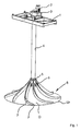
- Fig. 1 shows a stirring device in which a frame 1 shown in sections, a drive device 2 is received with a gear 3.
- a shaft 4 which z. B. consists of a tube made of fiber-reinforced plastic.
- a shaft 4 which z. B. consists of a tube made of fiber-reinforced plastic.
- agitator 6 is attached at a provided at the end of the shaft 4 flange 5 .
- the stirring body 6 has a hyperboloid-like shape.
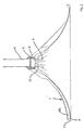
- On its top O ribs 7 are provided.
- a cross-sectional area F of the ribs 7 is formed asymmetrically with a steeply rising flank and a gently sloping flank.
- the ribs 7 extend from a peripheral edge Ur of the stirring body 6 in the direction of the shaft 4.
- the ribs 7 are curved, preferably hyperboloid-like.
- a steep flank of the ribs 7 forming profile is in Fig. 5 designated by the reference F1, a gently sloping edge with the reference F2.
- Fig. 1 to 5 are marked with the reference numeral 8 breakthroughs, which are provided in the vicinity of the shaft 4 and in the vicinity of a mounting portion 9 of the stirring body 6.
- the openings 8 are arranged between the ribs 7. They have an elongated or slit-like shape and extend substantially parallel to the ribs 7.
- a first height h1 increases steadily in a first section A1 extending from the peripheral edge Ur in the direction of the fastening section 9.
- the first height h1 is at a first end E1 of the first section A1 maximum.
- the first height h1 steadily decreases in a second section A2 extending from the first end E1 in the direction of the fastening section 9. It is zero near the attachment section 9.
- a ratio of the lengths of sections A1 / A2 may be in the range of 0.5 to 1.5.
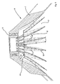
- Fig. 6 shows a perspective view of a partially broken stirrer 6.
- a bottom U further ribs 10 are provided, which extend from the attachment portion 9 and a central portion of the stirring body 6 radially in the direction of (not visible here) peripheral edge Ur.
- a second height h2 of the further ribs 10 also increases in a third section A3 which extends from the attachment section 9 in the direction of the peripheral edge Ur.
- the second height h2 is maximum. It steadily decreases to zero in a fourth section A4 extending from the further end E2 in the direction of the peripheral edge Ur.
- the further ribs 10 have a horizontal section Ah, which serves a support surface for stacking the stirring body 6 on the attachment section 9 of a further stirring body located therebelow.
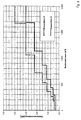
- the advantageous mode of operation of the stirring device is particularly based on the in Fig. 7 shown clearly comparative results.
- the measured values marked with a circle have been obtained with a stirring body on whose upper sides ribs with a constant first rib height have been provided.
- the measured values marked with a cross have been achieved with a further stirring body, on the upper side of which ribs with a constant second rib height have been attached.
- the second rib height has been greater than the first rib height.
- the measurements marked with squares have been achieved with a stirring body according to the invention.
- Comparatively illustrated measured values impressively show the improved efficiency of the agitator 6 according to the invention.
- a sol velocity at the bottom of a tank filled with a liquid is up to 30% higher than the sol velocities achievable with conventional agitating bodies.
- Fig. 8 the power input of a conventional stirring element (Generation 5) is plotted against the pelvic volume in comparison to a stirring element (Generation 6) according to the invention.
- the conventional stirrer body (Generation 5) was a stirring body, as it is known from US Pat DE 298 03 497 U1 is known. How out Fig. 8 it can be seen, with the stirrer according to the invention (Generation 6), for example, with a tank volume of 1000 m 3, the power input can be reduced by 40% compared to the conventional stirrer body (Generation 5).
- Fig. 9 shows the rated motor power for the conventional agitator (Generation 5) according to the DE 298 03 497 U1 relative to the stirrer according to the invention (Generation 6) above the pelvic volume.
- the rated motor power to drive the compared stirring body at a pool volume of 1000 m 3 of about 2.2 kW in the conventional agitator (generation 5) can be reduced to 1.5 kW in a stirring body (generation 6) according to the invention. This corresponds to a saving of more than 30% of the power to be installed, ie the energy to be provided.
Abstract
Description
Die Erfindung betrifft eine Rührvorrichtung nach dem Oberbegriff des Anspruchs 1, Sie betrifft ferner ein Verfahren zur Abwasserbehandlung.The invention relates to a stirring device according to the preamble of claim 1, it also relates to a method for wastewater treatment.
Eine gattungsgemäße Rührvorrichtung ist beispielsweise aus der
Die bekannten Rührvorrichtungen weisen eine hyperboloidartigen Rührkörper auf, an dessen Oberseite mehrere vom Umfangsrand in Richtung einer Welle verlaufende Rippen vorgesehen sind. Eine Höhe der Rippen ist dabei entweder gleich bleibend oder sie nimmt vom Umfangsrand in Richtung der Welle ab. Derartige hyperboloidartige Rührkörper haben sich wegen ihrer guten Rühreigenschaften insbesondere im Bereich der Abwasserbehandlung durchgesetzt. Gleichwohl wäre eine weitere Steigerung der Effizienz derartiger Rührkörper wünschenswert.The known stirring devices have a hyperboloid-like stirring body, on the upper side of which a plurality of ribs extending from the peripheral edge in the direction of a shaft are provided. A height of the ribs is either constant or decreases from the peripheral edge in the direction of the shaft. Such hyperboloidal stirring bodies have prevailed in particular in the field of wastewater treatment because of their good stirring properties. Nevertheless, a further increase in the efficiency of such stirring bodies would be desirable.
Aufgabe der Erfindung ist es, eine Rührvorrichtung mit verbesserter Effizienz anzugeben. Nach einem weiteren Ziel der Erfindung soll ein möglichst effizientes Verfahren zur Abwasserbehandlung angegeben werden.The object of the invention is to provide a stirring device with improved efficiency. According to a further object of the invention, a method of wastewater treatment which is as efficient as possible should be specified.
Diese Aufgabe wird durch die Merkmale der Ansprüche 1 und 14 gelöst. Zweckmäßige Ausgestaltungen ergeben sich aus den Merkmalen der Ansprüche 2 bis 13 und 15.This object is solved by the features of claims 1 and 14. Advantageous embodiments emerge from the features of
Nach Maßgabe der Erfindung ist vorgesehen, dass eine erste Höhe der Rippen zumindest abschnittsweise vom Umfangsrand des Rührkörpers in Richtung der Welle zunimmt. Damit kann überraschenderweise eine erhebliche Steigerung der Effizienz der Rührvorrichtung erreicht werden. Versuche haben ergeben, dass bei Verwendung eines mit den erfindungsgemäßen Rippen versehenen hyperboloidartigen Rührkörpers, die Effizienz um mehr als 20% gesteigert werden kann. In geeigneten Ausgestaltungsformen der Erfindung ist sogar eine Effizienzsteigerung um etwa 30% erzielt worden.According to the invention it is provided that a first height of the ribs increases at least in sections from the peripheral edge of the stirring body in the direction of the shaft. Thus, surprisingly, a considerable increase in the efficiency of the stirring device can be achieved. Experiments have shown that when using a provided with the ribs according to the invention hyperboloid-like stirring body, the efficiency can be increased by more than 20%. In suitable embodiments of the invention, even an increase in efficiency of about 30% has been achieved.
Unter einer "Höhe" der Rippen wird die Länge einer von einer Oberkante der Rippen bis zur Oberfläche des hyperboloidartigen Rührkörpers reichenden Normalen verstanden.A "height" of the ribs is understood to be the length of a normal reaching from an upper edge of the ribs to the surface of the hyperboloid-like stirring body.
Nach einer Ausgestaltung der Erfindung nimmt die Höhe in einem vom Umfangsrang in Richtung der Welle verlaufenden ersten Abschnitt zu und in einem von einem ersten Ende des ersten Abschnitts weiter in Richtung der Welle verlaufenden zweiten Abschnitt ab. Die Rippen können in Draufsicht auf die Oberseite eine Krümmung aufweisen, welche insbesondere hyperbolisch ausgebildet sein kann. Rippen mit den vorgenannten Merkmalen ermöglichen eine effiziente Übertragung der Rotationsenergie des Rührkörpers auf eine diesen umgebende Flüssigkeit.According to one embodiment of the invention, the height decreases in a direction extending from the circumferential rank in the direction of the first shaft portion and in a further from a first end of the first portion extending in the direction of the shaft second portion. The ribs may have a curvature in plan view of the top, which may be formed in particular hyperbolic. Ribs having the aforementioned features enable efficient transmission of the rotational energy of the stirring body to a liquid surrounding it.
Nach einer weiteren besonders vorteilhaften Ausgestaltung weist der Rührkörper mehrere in der Nähe der Welle vorgesehene Durchbrüche auf. Die Durchbrüche sind zweckmäßigerweise regelmäßig, vorzugsweise im selben radialen Abstand, angeordnet. Die vorgeschlagenen Durchbrüche ermöglichen einerseits einen Austritt von sich unterhalb des Rührkörpers möglicherweise bildenden Gasblasen. Sie ermöglichen aber auch die Ausbildung einer axialen, zum Boden eines Beckens, in welchen der Rührkörper ragt, gerichteten Strömung. Eine solche Strömung trägt dazu bei, dass sich ggf. unterhalb des Rührkörpers ausbildende Ablagerungen, beispielsweise Sand und dgl., entfernt werden.According to a further particularly advantageous embodiment, the stirring body has a plurality of openings provided in the vicinity of the shaft. The openings are expediently arranged regularly, preferably at the same radial distance. The proposed breakthroughs allow on the one hand an escape of gas bubbles possibly forming below the stirring body. But they also allow the formation of an axial, to the bottom of a basin, in which the stirring body protrudes directed flow. Such a flow contributes to the fact that possibly deposits forming below the stirring body, for example sand and the like, are removed.
Nach einer weiteren zweckmäßigen Ausgestaltung sind an einer der Oberseite gegenüberliegenden Unterseite des Rührkörpers mehrere in Richtung des Umfangsrands verlaufende weitere Rippen vorgesehen. Die weiteren Rippen können radial verlaufen. Eine zweite Höhe der weiteren Rippen nimmt zweckmäßigerweise in einem von einem zentralen Bereich des Rührkörpers in Richtung des Umfangsrands verlaufenden Abschnitt zu und in einem von einem zweiten Ende des dritten Abschnitts weiter in Richtung des Umfangsrands verlaufenden vierten Abschnitt ab. Des Weiteren können die weiteren Rippen jeweils einen horizontalen Abschnitt zum Abstützen auf einem zu Transport- oder Lagerzwecken darunter gestapelten Rührelements aufweisen. Die vorgeschlagenen weiteren Rippen erzeugen bei einer Rotation des Rührkörpers einen Unterdruck. Infolgedessen wird oberhalb des Rührkörpers befindliche Flüssigkeit durch die in der Nähe der Rippen vorgesehenen Durchbrüche angesaugt und axial in Richtung eines Bodens eines Abwasserbeckens beschleunigt. Damit kann die Effizienz der Rührwirkung weiter gesteigert werden. Versuche haben ergeben, dass das Vorsehen der weiteren Rippen eine Effizienzsteigerung von etwa 8 bis 10% bewirkt. Abgesehen davon können durch die durch die Wirkung der weiteren Rippen in Kombination mit den Durchbrüchen sich ausbildende, zum Boden eines Beckens gerichtete Axialströmung und dadurch bedingte Ablagerungen unterhalb des Rührkörpers sicher und zuverlässig vermieden werden.According to a further expedient embodiment, a plurality of further ribs extending in the direction of the peripheral edge are provided on an underside of the stirring body opposite the upper side. The further ribs can extend radially. A second height of the further ribs expediently decreases in a section running from a central region of the stirring body in the direction of the peripheral edge and in a fourth section extending further from the second end of the third section in the direction of the peripheral edge. Furthermore, the further ribs may each have a horizontal section for supporting on a stirring element stacked below for transport or storage purposes. The proposed further ribs generate a negative pressure during a rotation of the stirring body. As a result, liquid located above the agitating body is sucked through the apertures provided in the vicinity of the ribs and accelerated axially in the direction of a bottom of a wastewater basin. Thus, the efficiency of the stirring effect can be further increased. Experiments have shown that the provision of the further ribs causes an increase in efficiency of about 8 to 10%. Apart from that can be safely and reliably avoided by the effect of the further ribs in combination with the breakthroughs forming, directed to the bottom of a basin axial flow and consequent deposits below the stirring body.
Die Rippen verlaufen zweckmäßigerweise vom Umfangsrand bis in die Nähe der Welle, d. h. ihre Länge erstreckt sich im Wesentlichen über die gesamte radiale Distanz der Oberseite. Im Gegensatz dazu erstrecken sich die weiteren Rippen zweckmäßigerweise nicht bis zum Umfangsrand. Ihre radiale Erstreckung ist vorteilhafterweise höchstens halb so groß wie die der Rippen.The ribs expediently extend from the peripheral edge to near the shaft, ie their length extends essentially over the entire radial distance of the upper side. In contrast, the further ribs expediently do not extend to the peripheral edge. Their radial extent is advantageously at most half as large as that of the ribs.
Nach einem alternativen Gegenstand der Erfindung kann zur Steigerung der Effizienz auch eine Rührvorrichtung vorgesehen sein, bei der ein hyperboloidartiger Rührkörper über eine Welle mit einer Antriebseinrichtung verbunden ist, wobei der Rührkörper mehrere in der Nähe der Welle vorgesehene Durchbrüche aufweist, und wobei an einer Unterseite des Rührkörpers mehrere in Richtung des Umfangsrands verlaufende weitere Rippen vorgesehen sind. Hinsichtlich der Ausgestaltungen der weiteren Rippen wird auf die obigen Ausführungen verwiesen. Der hier beschriebene alternative Gegenstand der Erfindung kann selbstverständlich auch mit den vorbeschriebenen, auf der Oberseite des Rührkörpers vorgesehenen Rippen und deren vorteilhaften Ausgestaltungsformen kombiniert werden.According to an alternative object of the invention may be provided to increase the efficiency of a stirring device in which a hyperboloid-like stirring body is connected via a shaft with a drive means, wherein the stirring body has a plurality provided in the vicinity of the shaft openings, and wherein at an underside of the Rührkörpers more in the direction of the peripheral edge extending further ribs are provided. With regard to the embodiments of the further ribs, reference is made to the above statements. The alternative object of the invention described here can of course also be combined with the above-described ribs provided on the upper side of the stirring body and their advantageous embodiments.
Nach einer weiteren Ausgestaltung ist der Rührkörper zusammen mit den Rippen und/oder den weiteren Rippen aus einem Stück, vorzugsweise aus einem faserverstärkten Kunststoff, hergestellt. Das erleichtert die Herstellung und erhöht die Stabilität des vorgeschlagenen Rührkörpers. Es kann insbesondere auf herkömmliche und gut beherrschte Herstellungstechniken zurückgegriffen werden.According to a further embodiment of the stirring body is made together with the ribs and / or the other ribs in one piece, preferably made of a fiber-reinforced plastic. This facilitates the production and increases the stability of the proposed stirring body. In particular, conventional and well-controlled production techniques can be used.
Nach einer weiteren Ausgestaltung ist eine Abwasserbehandlungseinrichtung mit zumindest einer erfindungsgemäßen Rührvorrichtung vorgesehen, wobei das an der Welle aufgenommene Rührelement in ein Becken ragt und die Antriebseinrichtung an einem Gestell außerhalb des Beckens aufgenommen ist. Bei dem Gestell kann es sich um ein vom Rand des Beckens her in Richtung des Beckens erstreckendes brückenartiges Gestell handeln. Das Gestell kann auf einem Boden des Beckens abgestützt sein. Es ist aber auch möglich, dass der Rührkörper an einem vollständig auf dem Boden des Beckens abgestützten turmartigen Gestell aufgenommen ist, wobei wiederum eine Antriebseinrichtung außerhalb des Beckens aufgenommen ist. Selbstverständlich ist es auch möglich, den Rührkörper mittels Antriebseinrichtung anzutreiben, welche als Taucheinrichtung unterhalb eines Spiegels der zu rührenden Flüssigkeit an einem Gestell aufgenommen ist.According to a further embodiment, a wastewater treatment device is provided with at least one stirring device according to the invention, wherein the stirring element accommodated on the shaft protrudes into a basin and the drive device is received on a frame outside the basin. The frame can be a bridge-like frame extending from the edge of the pelvis in the direction of the pelvis. The frame can be supported on a floor of the basin. However, it is also possible for the stirring body to be accommodated on a tower-like frame supported completely on the bottom of the basin, wherein in turn a drive device is accommodated outside the basin. Of course, it is also possible, the stirring body by means of drive means to drive, which is received as a dipping device below a mirror of the liquid to be stirred on a frame.
Nach einer weiteren Ausgestaltung ist vorgesehen, dass eine Belüftungseinrichtung vorgesehen ist. Eine solche Belüftungseinrichtung ermöglicht insbesondere bei einer Abwasserbehandlung einen besonders effizienten Abbau von Schadstoffen im Abwasser. Es kann sich dabei um am Boden des Beckens verlegte Rohre oder Schläuche handeln, welche zum Belüftung mit Öffnungen, Schlitzen und dgl, versehen sind. Die Belüftungseinrichtung kann aber auch Bestandteil der Rührvorrichtung sein. So kann die Luft beispielsweise durch ein in das Becken reichendes Gestell oder durch die Welle der Rührvorrichtung in die Flüssigkeit gedrückt werden.According to a further embodiment, it is provided that a ventilation device is provided. Such a ventilation device allows a particularly efficient degradation of pollutants in wastewater, especially in a wastewater treatment. These may be pipes or hoses laid at the bottom of the tank, which are provided with openings, slots and the like for ventilation. The ventilation device can also be part of the stirring device. For example, the air may be forced into the liquid through a rack extending into the basin or through the shaft of the stirring device.
Nach weiterer Maßgabe der Erfindung ist ein Verfahren zur Abwasserbehandlung mit folgenden Schritten vorgesehen:
- a) Bereitstellen eines Beckens zur Aufnahme von Abwasser, einer erfindungsgemäßen Rührvorrichtung zum Umwälzen von im Becken aufgenommenem Abwasser sowie einer im Becken vorgesehenen Belüftungseinrichtung,
- b) Befüllen des Beckens mit Abwasser,
- c) Belüften des Abwassers mit der Belüftungsvorrichtung für eine vorgegebene Zeitdauer,
- d) Umwälzen des Abwassers mit der Rührvorrichtung für eine weitere vorgegebene Zeitdauer,
- e) Abschalten der Rührvorrichtung, so dass ein im Abwasser enthaltener Schlamm sich absetzen kann und
- f) Entfernen des behandelten Abwassers aus dem Becken.
- a) providing a basin for receiving wastewater, a stirring device according to the invention for circulating wastewater received in the basin and a ventilation device provided in the basin,
- b) filling the basin with wastewater,
- c) aerating the waste water with the aeration device for a predetermined period of time,
- d) circulating the wastewater with the stirrer for a further predetermined period of time,
- e) switching off the stirring device so that a sludge contained in the wastewater can settle and
- f) removing the treated wastewater from the basin.
Die Schritte lit. c) und d) können wechselweise mehrfach wiederholt werden. Es ist auch möglich, den Schritt lit. d) vor dem Schritt lit. c) auszuführen. Das vorgeschlagene Verfahren ermöglicht einen besonders effizienten Abbau von im Abwasser enthaltenen Schadstoffen.The steps lit. c) and d) can be repeated several times alternately. It is also possible to step lit. d) before step lit. c) execute. The proposed method allows a particularly efficient removal of pollutants contained in the wastewater.
Nachfolgend werden Ausführungsbeispiele der Erfindung anhand der Zeichnungen näher erläutert. Es zeigen:
- Fig. 1
- eine perspektivische Ansicht einer Rührvorrichtung,
- Fig. 2
- eine Querschnittsansicht durch den Rührkörper gemäß
Fig. 1 , - Fig. 3
- eine perspektivische Detailansicht des Rührkörpers gemäß
Fig. 1 , - Fig. 4
- eine perspektivische Ansicht auf den Rührkörper gemäß
Fig. 1 , - Fig. 5
- eine Draufsicht auf den Rührkörper gemäß
Fig. 4 , - Fig. 6
- eine perspektivische teilweise aufgebrochene Ansicht des Rührkörpers gemäß
Fig. 1 , - Fig. 7
- die mit verschiedenen Rührkörpern erzielten Solgeschwindigkeiten in Abhängigkeit von der Entfernung vom Rührkörper,
- Fig. 8
- den Leistungseintrag über dem Beckenvolumen für einen erfindungsgemäßen Rührkörper im Vergleich zu einem herkömmlichen Rührkörper und
- Fig. 9
- die Motornennleistung über dem Beckenvolumen für einen erfindungsgemäßen Rührkörper im Vergleich zu einem herkömmlichen Rührkörper.
- Fig. 1
- a perspective view of a stirring device,
- Fig. 2
- a cross-sectional view through the stirring body according to
Fig. 1 . - Fig. 3
- a detailed perspective view of the stirring body according to
Fig. 1 . - Fig. 4
- a perspective view of the stirring body according to
Fig. 1 . - Fig. 5
- a plan view of the stirring body according to
Fig. 4 . - Fig. 6
- a perspective partially broken view of the stirring body according to
Fig. 1 . - Fig. 7
- the sol speeds achieved with different stirring bodies as a function of the distance from the stirring body,
- Fig. 8
- the power input over the pool volume for a stirring body according to the invention in comparison to a conventional stirring body and
- Fig. 9
- the rated motor power over the tank volume for a stirring element according to the invention in comparison with a conventional stirring element.
In den
Wie insbesondere aus
Die weiteren Rippen 10 weisen einen horizontalen Abschnitt Ah auf, welcher eine Auflagefläche zum Stapeln des Rührkörpers 6 auf dem Befestigungsabschnitt 9 eines darunter befindlichen weiteren Rührkörpers dient.The
Die vorteilhafte Wirkungsweise der Rührvorrichtung wird insbesondere anhand der in
In
- 11
- Gestellframe
- 22
- Antriebseinrichtungdriving means
- 33
- Getriebetransmission
- 44
- Wellewave
- 55
- Flanschflange
- 66
- Rührkörperagitator
- 77
- Ripperib
- 88th
- Durchbruchbreakthrough
- 99
- Befestigungsabschnittattachment section
- 1010
- weitere Rippeanother rib
- A1A1
- erster Abschnittfirst section
- A2A2
- zweiter Abschnittsecond part
- A3A3
- dritter Abschnittthird section
- A4A4
- vierter Abschnittfourth section
- AhAh
- horizontaler Abschnitthorizontal section
- E1E1
- erstes Endefirst end
- E2E2
- zweites Endesecond end
- F1F1
- steile Flankesteep flank
- F2F2
- flache Flankeflat flank
- h1h1
- erste Höhefirst height
- h2h2
- zweite Höhesecond height
- OO
- Oberseitetop
- UU
- Unterseitebottom
- Urur
- Umfangsrandcircumferential edge
Claims (15)
- Agitating device on which a hyperboloid-like agitating body (6) is connected with a drive unit (2, 3) via a shaft (4), wherein a plurality of ribs (7) is provided on an upper side (O) of the agitating body (6) running from the circumferential boundary (Ur) in the direction of the shaft (4),
characterized in that
a first height (h1) of the ribs (7) increases at least in sections from the circumferential boundary (Ur) of the agitating body (6) in the direction of the shaft (4). - Agitating device as defined in claim 1, wherein the first height (h1) increases in a first section (A1) running from the circumferential boundary (Ur) in the direction of the shaft (4) and decreases in a second section (A2) running from a first end (E1) of the first section (A1) further in the direction of the shaft (4).
- Agitating device as defined in one of the preceding claims, wherein the ribs (7) show a bend in the top view of the upper side (O).
- Agitating device as defined in one of the preceding claims, wherein the bend is a hyperbolic bend.
- Agitating device as defined in one of the preceding claims, wherein the agitating body (6) has a plurality of breakthroughs (8) provided in the vicinity of the shaft (4).
- Agitating device as defined in one of the preceding claims, wherein the breakthroughs (8) are arranged at regular intervals, preferably at the same radial distance.
- Agitating device as defined in one of the preceding claims, wherein a plurality of further ribs (10) is provided on an underside (U) of the agitating body (6) opposite the upper side (O) running in the direction of the circumferential boundary (Ur).
- Agitating device as defined in one of the preceding claims, wherein the further ribs (10) run radially.
- Agitating device as defined in one of the preceding claims, wherein a second height (h2) of the further ribs (10) increases in a third section (A3) running from a central area of the agitating body (6) in the direction of the circumferential boundary (Ur) and decreases in a fourth section (A4) running from a second end (E2) of the third section (A3) further in the direction of the circumferential boundary (Ur).
- Agitating device as defined in one of the preceding claims, wherein the further ribs (10) each have a horizontal section (Ah) to support a further agitating element stacked beneath for transport or storage purposes.
- Agitating device as defined in one of the preceding claims, wherein the agitating body (6) together with the ribs (7) and/or the further ribs (10) is manufactured from one piece, preferably from a fiber-reinforced plastic.
- Sewage treatment unit with at least one agitating device as defined in one of the preceding claims, wherein the agitating element (6) held on the shaft (4) protrudes into a basin and the drive unit (2, 3) is held on a frame (1) outside the basin.
- Sewage treatment unit as defined in claim 12, wherein an aeration unit is provided in the basin.
- Method for sewage treatment having the following steps:a) Providing a basin to hold the sewage, an agitating device according to one of the preceding claims to circulate the sewage held in the basin as well as an aeration device provided in the basin,b) Filling the basin with sewage,c) Aerating the sewage with the aeration device for a specified amount of time,d) Circulating the sewage with the agitating device for a further specified amount of time,e) Turning off the agitating device so that a sludge contained in the sewage can settle andf) Removing the treated sewage from the basin.
- Method as defined in claim 14, wherein steps c and d are repeated alternately a plurality of times.
Priority Applications (1)
| Application Number | Priority Date | Filing Date | Title |
|---|---|---|---|
| PL06724030T PL1868710T3 (en) | 2005-04-12 | 2006-04-05 | Agitating device and method for sewage treatment |
Applications Claiming Priority (2)
| Application Number | Priority Date | Filing Date | Title |
|---|---|---|---|
| DE102005016948A DE102005016948B3 (en) | 2005-04-12 | 2005-04-12 | Stirring device and process for wastewater treatment |
| PCT/EP2006/003077 WO2006108538A1 (en) | 2005-04-12 | 2006-04-05 | Agitating device and method for sewage treatment |
Publications (2)
| Publication Number | Publication Date |
|---|---|
| EP1868710A1 EP1868710A1 (en) | 2007-12-26 |
| EP1868710B1 true EP1868710B1 (en) | 2008-09-17 |
Family
ID=36603511
Family Applications (1)
| Application Number | Title | Priority Date | Filing Date |
|---|---|---|---|
| EP06724030A Active EP1868710B1 (en) | 2005-04-12 | 2006-04-05 | Agitating device and method for sewage treatment |
Country Status (10)
| Country | Link |
|---|---|
| US (1) | US7784769B2 (en) |
| EP (1) | EP1868710B1 (en) |
| CN (1) | CN100571853C (en) |
| AT (1) | ATE408449T1 (en) |
| CA (1) | CA2603984C (en) |
| DE (2) | DE102005016948B3 (en) |
| DK (1) | DK1868710T3 (en) |
| ES (1) | ES2313634T3 (en) |
| PL (1) | PL1868710T3 (en) |
| WO (1) | WO2006108538A1 (en) |
Families Citing this family (20)
| Publication number | Priority date | Publication date | Assignee | Title |
|---|---|---|---|---|
| US7954789B2 (en) * | 2007-01-03 | 2011-06-07 | Jet, Inc. | Composite shaft and self-centering coupling |
| US7954790B2 (en) * | 2007-01-03 | 2011-06-07 | Jet, Inc. | Composite shaft aspirator assembly |
| PL2175972T3 (en) * | 2007-08-09 | 2012-10-31 | Invent Umwelt & Verfahrenstech | Stirring device for activated sludges |
| DE102007037586B3 (en) * | 2007-08-09 | 2008-09-18 | Invent Umwelt- Und Verfahrenstechnik Ag | Stirring device for activated sludge |
| WO2009018915A1 (en) * | 2007-08-09 | 2009-02-12 | Invent Umwelt- Und Verfahrenstechnik Ag | Stirring device for activated sludges |
| DE102009045032A1 (en) * | 2009-09-25 | 2011-03-31 | Invent Umwelt-Und Verfahrenstechnik Ag | Process and apparatus for the biological purification of wastewater |
| DE102010000730B4 (en) * | 2010-01-07 | 2011-12-15 | Invent Umwelt- Und Verfahrenstechnik Ag | Vertical agitator for wastewater collected in a clarifier |
| WO2013082717A1 (en) * | 2011-12-06 | 2013-06-13 | Bachellier Carl Roy | Improved impeller apparatus and dispersion method |
| DE102013225659A1 (en) * | 2013-12-11 | 2015-06-11 | Invent Umwelt- Und Verfahrenstechnik Ag | Device for circulating a liquid received in a container |
| DE102013225658A1 (en) | 2013-12-11 | 2015-06-11 | Invent Umwelt- Und Verfahrenstechnik Ag | Agitator and stirrer for generating a flow in a waste water treatment tank |
| DE102013225662A1 (en) | 2013-12-11 | 2015-06-11 | Invent Umwelt- Und Verfahrenstechnik Ag | Stirring device for circulating wastewater and equipment received in a basin |
| US9863423B2 (en) | 2014-04-14 | 2018-01-09 | Enevor Inc. | Conical impeller and applications thereof |
| US10173184B2 (en) * | 2015-03-25 | 2019-01-08 | Schlumberger Technology Corporation | Blender for mixing and pumping solids and fluids and method of use thereof |
| CN106732005B (en) * | 2017-01-18 | 2023-10-27 | 北京首创环境科技有限公司 | Stirring equipment |
| CN106994307A (en) * | 2017-04-07 | 2017-08-01 | 南京中德环保设备制造有限公司 | A kind of vertical mixer high-efficiency stirring turbine |
| RU2683078C1 (en) * | 2018-06-06 | 2019-03-26 | Непубличное акционерное общество "Астерион" | Mixing device |
| DE102019101416B4 (en) * | 2018-12-03 | 2020-07-16 | Invent Umwelt- Und Verfahrenstechnik Ag | Hyperboloid stirring body for circulating liquids as well as stirring and gassing equipment |
| JP7237561B2 (en) * | 2018-12-19 | 2023-03-13 | プライミクス株式会社 | Stirrer and Stirrer |
| CN109824104A (en) * | 2019-04-10 | 2019-05-31 | 尚川(北京)水务有限公司 | A kind of Double-curved-surface stirring device |
| DE102019111492A1 (en) * | 2019-05-03 | 2020-11-05 | Invent Umwelt-Und Verfahrenstechnik Ag | Propeller and agitator for circulating wastewater in a clarifier |
Family Cites Families (4)
| Publication number | Priority date | Publication date | Assignee | Title |
|---|---|---|---|---|
| SU1007714A1 (en) * | 1974-07-10 | 1983-03-30 | Dmitriev Igor A | Apparatus for ajitating components |
| DE4218027A1 (en) * | 1991-05-30 | 1992-12-03 | Marcus Dipl Ing Hoefken | Fluid agitation and aeration - has hyperboloid agitator body which separates actions for min. energy consumption |
| DE29803497U1 (en) * | 1998-02-27 | 1999-06-24 | Invent Umwelt & Verfahrenstech | Agitator arrangement |
| DE19826098C2 (en) | 1998-06-12 | 2002-03-14 | Franz Durst | stirrer |
-
2005
- 2005-04-12 DE DE102005016948A patent/DE102005016948B3/en not_active Expired - Fee Related
-
2006
- 2006-04-05 CN CNB2006800116088A patent/CN100571853C/en active Active
- 2006-04-05 DK DK06724030T patent/DK1868710T3/en active
- 2006-04-05 CA CA2603984A patent/CA2603984C/en active Active
- 2006-04-05 WO PCT/EP2006/003077 patent/WO2006108538A1/en active IP Right Grant
- 2006-04-05 AT AT06724030T patent/ATE408449T1/en active
- 2006-04-05 US US11/886,950 patent/US7784769B2/en active Active
- 2006-04-05 EP EP06724030A patent/EP1868710B1/en active Active
- 2006-04-05 DE DE502006001605T patent/DE502006001605D1/en active Active
- 2006-04-05 PL PL06724030T patent/PL1868710T3/en unknown
- 2006-04-05 ES ES06724030T patent/ES2313634T3/en active Active
Also Published As
| Publication number | Publication date |
|---|---|
| US20090127213A1 (en) | 2009-05-21 |
| EP1868710A1 (en) | 2007-12-26 |
| DE102005016948B3 (en) | 2007-01-04 |
| WO2006108538A1 (en) | 2006-10-19 |
| CA2603984C (en) | 2010-07-13 |
| CA2603984A1 (en) | 2006-10-19 |
| CN101155626A (en) | 2008-04-02 |
| PL1868710T3 (en) | 2009-03-31 |
| DE502006001605D1 (en) | 2008-10-30 |
| US7784769B2 (en) | 2010-08-31 |
| ES2313634T3 (en) | 2009-03-01 |
| CN100571853C (en) | 2009-12-23 |
| ATE408449T1 (en) | 2008-10-15 |
| DK1868710T3 (en) | 2009-01-12 |
Similar Documents
| Publication | Publication Date | Title |
|---|---|---|
| EP1868710B1 (en) | Agitating device and method for sewage treatment | |
| DE2461032C3 (en) | Device for gassing and circulating e.g. aqueous liquids | |
| DE3126527A1 (en) | "DEVICE SUITABLE TO MIX A GAS WITH A LIQUID AND REVERSE OR TO DEGASS A LIQUID" | |
| EP2613871B1 (en) | Stirrer | |
| EP0017064A1 (en) | Apparatus for the aeration of waste water or sludge | |
| DE69932115T2 (en) | Agitator with vertical axis | |
| WO2009018915A1 (en) | Stirring device for activated sludges | |
| WO2008101632A1 (en) | Horizontal agitator and method for producing a flow in a clearing basin using the horizontal agitator | |
| EP2125180A1 (en) | Horizontal agitator and method for producing a flow in a clearing basin using the horizontal agitator | |
| EP1854764B1 (en) | Reactor comprising a stack of filter plates | |
| EP0564935A1 (en) | Sewage treatment plant | |
| EP2480504B1 (en) | Method and device for biologically cleaning wastewater | |
| CH690835A5 (en) | Stirring assembly for liquid manure within a storage tank has structured stirrers with part surfaces at an angle to each other on lateral carriers with different dimensions to give a consistent liquid without precipitated solids | |
| EP2828210B1 (en) | Arrangement and method for producing a flow in a wastewater treatment tank | |
| DE2238869A1 (en) | PROCESS AND SYSTEM FOR PURIFYING WASTE WATER | |
| DE2407409B2 (en) | Floating device for removing contaminants floating on a water surface | |
| WO2008101633A1 (en) | Horizontal agitator and method for producing a flow in a clearing basin using the horizontal agitator | |
| DE1963614A1 (en) | Surface gasifier or aerator for liquids | |
| DE2943335C2 (en) | ||
| DE102019111489A1 (en) | Sewage purification device and method for purifying sewage | |
| EP0147367A2 (en) | Waste water aeration system, process for its operation and use | |
| DE2349218B1 (en) | Purification plant for the biological purification of waste water | |
| DE3039423C2 (en) | Process for the biological purification of waste water | |
| CH350935A (en) | Process for aerating liquids and aerating rotor for carrying out the process | |
| DE102009016397A1 (en) | Process for swirling growth bodies in a clarifier and associated clarifier |
Legal Events
| Date | Code | Title | Description |
|---|---|---|---|
| PUAI | Public reference made under article 153(3) epc to a published international application that has entered the european phase |
Free format text: ORIGINAL CODE: 0009012 |
|
| 17P | Request for examination filed |
Effective date: 20070921 |
|
| AK | Designated contracting states |
Kind code of ref document: A1 Designated state(s): AT BE BG CH CY CZ DE DK EE ES FI FR GB GR HU IE IS IT LI LT LU LV MC NL PL PT RO SE SI SK TR |
|
| GRAP | Despatch of communication of intention to grant a patent |
Free format text: ORIGINAL CODE: EPIDOSNIGR1 |
|
| DAX | Request for extension of the european patent (deleted) | ||
| GRAS | Grant fee paid |
Free format text: ORIGINAL CODE: EPIDOSNIGR3 |
|
| GRAA | (expected) grant |
Free format text: ORIGINAL CODE: 0009210 |
|
| AK | Designated contracting states |
Kind code of ref document: B1 Designated state(s): AT BE BG CH CY CZ DE DK EE ES FI FR GB GR HU IE IS IT LI LT LU LV MC NL PL PT RO SE SI SK TR |
|
| REG | Reference to a national code |
Ref country code: GB Ref legal event code: FG4D Free format text: NOT ENGLISH |
|
| REG | Reference to a national code |
Ref country code: CH Ref legal event code: EP |
|
| REG | Reference to a national code |
Ref country code: IE Ref legal event code: FG4D Free format text: LANGUAGE OF EP DOCUMENT: GERMAN |
|
| REF | Corresponds to: |
Ref document number: 502006001605 Country of ref document: DE Date of ref document: 20081030 Kind code of ref document: P |
|
| REG | Reference to a national code |
Ref country code: CH Ref legal event code: NV Representative=s name: GLN GRESSET & LAESSER NEUCHATEL CABINET DE CONSEIL |
|
| REG | Reference to a national code |
Ref country code: DK Ref legal event code: T3 |
|
| REG | Reference to a national code |
Ref country code: SE Ref legal event code: TRGR |
|
| PG25 | Lapsed in a contracting state [announced via postgrant information from national office to epo] |
Ref country code: LT Free format text: LAPSE BECAUSE OF FAILURE TO SUBMIT A TRANSLATION OF THE DESCRIPTION OR TO PAY THE FEE WITHIN THE PRESCRIBED TIME-LIMIT Effective date: 20080917 |
|
| PG25 | Lapsed in a contracting state [announced via postgrant information from national office to epo] |
Ref country code: LV Free format text: LAPSE BECAUSE OF FAILURE TO SUBMIT A TRANSLATION OF THE DESCRIPTION OR TO PAY THE FEE WITHIN THE PRESCRIBED TIME-LIMIT Effective date: 20080917 Ref country code: SI Free format text: LAPSE BECAUSE OF FAILURE TO SUBMIT A TRANSLATION OF THE DESCRIPTION OR TO PAY THE FEE WITHIN THE PRESCRIBED TIME-LIMIT Effective date: 20080917 |
|
| REG | Reference to a national code |
Ref country code: ES Ref legal event code: FG2A Ref document number: 2313634 Country of ref document: ES Kind code of ref document: T3 |
|
| REG | Reference to a national code |
Ref country code: PL Ref legal event code: T3 |
|
| PG25 | Lapsed in a contracting state [announced via postgrant information from national office to epo] |
Ref country code: BG Free format text: LAPSE BECAUSE OF FAILURE TO SUBMIT A TRANSLATION OF THE DESCRIPTION OR TO PAY THE FEE WITHIN THE PRESCRIBED TIME-LIMIT Effective date: 20081217 |
|
| PG25 | Lapsed in a contracting state [announced via postgrant information from national office to epo] |
Ref country code: RO Free format text: LAPSE BECAUSE OF FAILURE TO SUBMIT A TRANSLATION OF THE DESCRIPTION OR TO PAY THE FEE WITHIN THE PRESCRIBED TIME-LIMIT Effective date: 20080917 Ref country code: IS Free format text: LAPSE BECAUSE OF FAILURE TO SUBMIT A TRANSLATION OF THE DESCRIPTION OR TO PAY THE FEE WITHIN THE PRESCRIBED TIME-LIMIT Effective date: 20090117 Ref country code: PT Free format text: LAPSE BECAUSE OF FAILURE TO SUBMIT A TRANSLATION OF THE DESCRIPTION OR TO PAY THE FEE WITHIN THE PRESCRIBED TIME-LIMIT Effective date: 20090217 Ref country code: SK Free format text: LAPSE BECAUSE OF FAILURE TO SUBMIT A TRANSLATION OF THE DESCRIPTION OR TO PAY THE FEE WITHIN THE PRESCRIBED TIME-LIMIT Effective date: 20080917 |
|
| PLBE | No opposition filed within time limit |
Free format text: ORIGINAL CODE: 0009261 |
|
| STAA | Information on the status of an ep patent application or granted ep patent |
Free format text: STATUS: NO OPPOSITION FILED WITHIN TIME LIMIT |
|
| PG25 | Lapsed in a contracting state [announced via postgrant information from national office to epo] |
Ref country code: EE Free format text: LAPSE BECAUSE OF FAILURE TO SUBMIT A TRANSLATION OF THE DESCRIPTION OR TO PAY THE FEE WITHIN THE PRESCRIBED TIME-LIMIT Effective date: 20080917 |
|
| 26N | No opposition filed |
Effective date: 20090618 |
|
| REG | Reference to a national code |
Ref country code: HU Ref legal event code: AG4A Ref document number: E006676 Country of ref document: HU |
|
| PG25 | Lapsed in a contracting state [announced via postgrant information from national office to epo] |
Ref country code: MC Free format text: LAPSE BECAUSE OF NON-PAYMENT OF DUE FEES Effective date: 20090430 |
|
| PG25 | Lapsed in a contracting state [announced via postgrant information from national office to epo] |
Ref country code: GR Free format text: LAPSE BECAUSE OF FAILURE TO SUBMIT A TRANSLATION OF THE DESCRIPTION OR TO PAY THE FEE WITHIN THE PRESCRIBED TIME-LIMIT Effective date: 20081218 |
|
| PG25 | Lapsed in a contracting state [announced via postgrant information from national office to epo] |
Ref country code: LU Free format text: LAPSE BECAUSE OF NON-PAYMENT OF DUE FEES Effective date: 20090405 |
|
| PG25 | Lapsed in a contracting state [announced via postgrant information from national office to epo] |
Ref country code: TR Free format text: LAPSE BECAUSE OF FAILURE TO SUBMIT A TRANSLATION OF THE DESCRIPTION OR TO PAY THE FEE WITHIN THE PRESCRIBED TIME-LIMIT Effective date: 20080917 |
|
| PG25 | Lapsed in a contracting state [announced via postgrant information from national office to epo] |
Ref country code: CY Free format text: LAPSE BECAUSE OF FAILURE TO SUBMIT A TRANSLATION OF THE DESCRIPTION OR TO PAY THE FEE WITHIN THE PRESCRIBED TIME-LIMIT Effective date: 20080917 |
|
| REG | Reference to a national code |
Ref country code: CH Ref legal event code: PFA Owner name: INVENT UMWELT- UND VERFAHRENSTECHNIK AG, DE Free format text: FORMER OWNER: INVENT UMWELT- UND VERFAHRENSTECHNIK AG, DE |
|
| REG | Reference to a national code |
Ref country code: FR Ref legal event code: PLFP Year of fee payment: 11 |
|
| REG | Reference to a national code |
Ref country code: CH Ref legal event code: PFA Owner name: INVENT UMWELT- UND VERFAHRENSTECHNIK AG, DE Free format text: FORMER OWNER: INVENT UMWELT- UND VERFAHRENSTECHNIK AG, DE |
|
| REG | Reference to a national code |
Ref country code: FR Ref legal event code: PLFP Year of fee payment: 12 |
|
| REG | Reference to a national code |
Ref country code: FR Ref legal event code: PLFP Year of fee payment: 13 |
|
| REG | Reference to a national code |
Ref country code: CH Ref legal event code: NV Representative=s name: BOVARD SA NEUCHATEL CONSEILS EN PROPRIETE INTE, CH |
|
| REG | Reference to a national code |
Ref country code: DE Ref legal event code: R079 Ref document number: 502006001605 Country of ref document: DE Free format text: PREVIOUS MAIN CLASS: B01F0003040000 Ipc: B01F0023200000 |
|
| PGFP | Annual fee paid to national office [announced via postgrant information from national office to epo] |
Ref country code: CZ Payment date: 20230327 Year of fee payment: 18 |
|
| PGFP | Annual fee paid to national office [announced via postgrant information from national office to epo] |
Ref country code: PL Payment date: 20230328 Year of fee payment: 18 |
|
| PGFP | Annual fee paid to national office [announced via postgrant information from national office to epo] |
Ref country code: NL Payment date: 20230417 Year of fee payment: 18 |
|
| PGFP | Annual fee paid to national office [announced via postgrant information from national office to epo] |
Ref country code: IT Payment date: 20230428 Year of fee payment: 18 Ref country code: IE Payment date: 20230425 Year of fee payment: 18 Ref country code: FR Payment date: 20230417 Year of fee payment: 18 Ref country code: ES Payment date: 20230517 Year of fee payment: 18 Ref country code: DK Payment date: 20230419 Year of fee payment: 18 Ref country code: DE Payment date: 20230418 Year of fee payment: 18 Ref country code: CH Payment date: 20230502 Year of fee payment: 18 |
|
| PGFP | Annual fee paid to national office [announced via postgrant information from national office to epo] |
Ref country code: SE Payment date: 20230419 Year of fee payment: 18 Ref country code: HU Payment date: 20230330 Year of fee payment: 18 Ref country code: FI Payment date: 20230417 Year of fee payment: 18 Ref country code: AT Payment date: 20230414 Year of fee payment: 18 |
|
| PGFP | Annual fee paid to national office [announced via postgrant information from national office to epo] |
Ref country code: BE Payment date: 20230417 Year of fee payment: 18 |
|
| PGFP | Annual fee paid to national office [announced via postgrant information from national office to epo] |
Ref country code: GB Payment date: 20230420 Year of fee payment: 18 |