EP1867419A1 - Machine de sciage pour la coupe de panneaux de bois ou similaires - Google Patents
Machine de sciage pour la coupe de panneaux de bois ou similaires Download PDFInfo
- Publication number
- EP1867419A1 EP1867419A1 EP07110425A EP07110425A EP1867419A1 EP 1867419 A1 EP1867419 A1 EP 1867419A1 EP 07110425 A EP07110425 A EP 07110425A EP 07110425 A EP07110425 A EP 07110425A EP 1867419 A1 EP1867419 A1 EP 1867419A1
- Authority
- EP
- European Patent Office
- Prior art keywords
- aspirating
- cutting
- pushing
- sawing machine
- machine according
- Prior art date
- Legal status (The legal status is an assumption and is not a legal conclusion. Google has not performed a legal analysis and makes no representation as to the accuracy of the status listed.)
- Granted
Links
Images


Classifications
-
- B—PERFORMING OPERATIONS; TRANSPORTING
- B27—WORKING OR PRESERVING WOOD OR SIMILAR MATERIAL; NAILING OR STAPLING MACHINES IN GENERAL
- B27B—SAWS FOR WOOD OR SIMILAR MATERIAL; COMPONENTS OR ACCESSORIES THEREFOR
- B27B5/00—Sawing machines working with circular or cylindrical saw blades; Components or equipment therefor
- B27B5/02—Sawing machines working with circular or cylindrical saw blades; Components or equipment therefor characterised by a special purpose only
- B27B5/06—Sawing machines working with circular or cylindrical saw blades; Components or equipment therefor characterised by a special purpose only for dividing plates in parts of determined size, e.g. panels
- B27B5/065—Sawing machines working with circular or cylindrical saw blades; Components or equipment therefor characterised by a special purpose only for dividing plates in parts of determined size, e.g. panels with feedable saw blades, e.g. arranged on a carriage
-
- B—PERFORMING OPERATIONS; TRANSPORTING
- B23—MACHINE TOOLS; METAL-WORKING NOT OTHERWISE PROVIDED FOR
- B23D—PLANING; SLOTTING; SHEARING; BROACHING; SAWING; FILING; SCRAPING; LIKE OPERATIONS FOR WORKING METAL BY REMOVING MATERIAL, NOT OTHERWISE PROVIDED FOR
- B23D59/00—Accessories specially designed for sawing machines or sawing devices
- B23D59/006—Accessories specially designed for sawing machines or sawing devices for removing or collecting chips
Definitions
- the present invention relates to a sawing machine for wood panels or the like.
- the present invention relates to a sawing machine of the type comprising supporting means defining a supporting plane for at least one panel; conveying means for feeding the panel in a first given direction; cutting means movable in a second direction transversal to the first direction and on a cutting plane orthogonal to the supporting plane for sawing the panel; pressing means movable in a third direction orthogonal to the supporting plane for securing the panel against the supporting plane itself; and at least one aspirating pipe for aspirating the shavings and/or the machining waste generated by the cutting means.
- the known sawing machines of the type described above present some drawbacks mainly deriving from the fact that the suction pipe, in use, is relatively far away from the cutting means and thus presents a relatively low efficiency because it is not capable of aspirating all the shavings and/or machining waste generated by the cutting means themselves, and implies the use of relatively high air flow rates.
- numeral 1 indicates as a whole a sawing machine for sawing wood panels 2 or the like, each of which presents a substantially parallelepiped shape with substantially rectangular section.
- Machine 1 comprises an elongated base 3, which extends in a horizontal direction 4, and supports a roller conveyor 5 comprising, in turn, a plurality of rollers 6, which define a supporting plane P for at least one panel 2, and are mounted to turn, with respect to base 3, about corresponding longitudinal axes 7 parallel to a horizontal direction 8 transversal to direction 4.
- Base 3 further presents two side longitudinal members 9, which extend parallel to direction 4, and which support a gripping and conveying unit 10 of known type comprising a horizontal cross member 11, which extends between longitudinal members 9 parallelly to direction 8, is slidingly coupled to longitudinal members 9 to perform intermittent rectilinear movements in direction 4, along longitudinal members 9 and under the bias of an actuating device of known type and not shown, and is provided with a plurality of pincer-like gripping members 12 distributed along cross member 11 itself.
- a gripping and conveying unit 10 of known type comprising a horizontal cross member 11, which extends between longitudinal members 9 parallelly to direction 8, is slidingly coupled to longitudinal members 9 to perform intermittent rectilinear movements in direction 4, along longitudinal members 9 and under the bias of an actuating device of known type and not shown, and is provided with a plurality of pincer-like gripping members 12 distributed along cross member 11 itself.
- Panels 2 are fed by unit 10 in direction 4 and to a cutting station 13 provided with a supporting table 14 coplanar to plane P and with a cutting unit 15.
- Unit 15 comprises a carriage 16, which extends underneath plane P, is slidingly coupled to base 3 for performing rectilinear movements in direction 8, with respect to base 3 under the bias of an actuating device of known type and not shown, and supports a cutter 17 and a cutting blade 18 rotationally coupled to carriage 16 to turn, with respect to carriage 16 itself, about corresponding longitudinal axes 19, 20.
- Cutter 17 and blade 18 extend on a vertical cutting plane T orthogonal to direction 4, and are fed by carriage 16 along a slot 21 obtained through table 14 parallelly to direction 8 to cut panels 2.
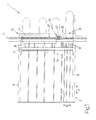
- Station 13 is further provided with a pressing device 22 comprising two cross members 23, which extend over plane P parallelly to direction 8, are arranged on opposite sides of plane T in direction 4, and are slidingly coupled to base 3 to perform, with respect to base 3 and under the bias of an actuating device of the known type and not shown, rectilinear movements in a vertical direction orthogonal to directions 4 and 8 between a raised rest position (figure 3), in which cross members 23 are arranged at a given distance from panels 2, and a lowered working position (figures 2 and 4), in which panels 2 are stabilised by cross members 23 to ensure a correct operative cycle of cutting unit 15.
- a pressing device 22 comprising two cross members 23, which extend over plane P parallelly to direction 8, are arranged on opposite sides of plane T in direction 4, and are slidingly coupled to base 3 to perform, with respect to base 3 and under the bias of an actuating device of the known type and not shown, rectilinear movements in a vertical direction orthogonal to directions 4 and 8 between a raised rest position (figure
- station 13 is provided with a pushing and aspirating unit 25 comprising two cross members 26, which are fixed to base 3 over cross members 23, extend in direction 8, and support a carriage 27, which extends between cross members 26, and is slidingly coupled to cross members 26 to perform, with respect to base 3 and under the bias of an actuating device of the known type and not shown, rectilinear movements in direction 8.
- a pushing and aspirating unit 25 comprising two cross members 26, which are fixed to base 3 over cross members 23, extend in direction 8, and support a carriage 27, which extends between cross members 26, and is slidingly coupled to cross members 26 to perform, with respect to base 3 and under the bias of an actuating device of the known type and not shown, rectilinear movements in direction 8.
- Carriage 27 supports a runner 28, which is fixed to an outlet rod 29 of an actuator cylinder 30 fitted on carriage 27, extends between cross members 23 of pressing device 22, and is mobile in direction 24 between a raised position (not shown) and a lowered position (figures 3 and 4).
- Runner 28 is substantially fork-shaped and comprises two pushing arms 31 (only one of which is shown in figures 3 and 4), which extend in direction 24, are arranged on opposite sides of plane T in direction 4 to be crossed by cutter 17 and blade 18 when runner 28 is arranged in its lowered position, and are adapted to move panels 2 onto contact with a side abutting element 32 extending parallelly to direction 4 and over plane P.
- pushing arms 31 may be made by blade 18, which saws runner 28 during a first operating cycle of cutting unit 15.
- Runner 28 is fixed to an aspirating pipe 33, which defines part of a pneumatic aspirating device 34 for aspirating the shavings and/or the machining waste generated by cutting unit 15, extends upwards between cross members 23 of pressing device 22, and presents a lower inlet mouth 35, which extends about plane T, and is shaped so as to be crossed by cutter 17 and blade 18 when runner 28 is arranged in its lowered position (figure 2).
- Pipe 33 is fluid-tightly coupled to cross members 23 by means of the interposing of two seals 36, which are fixed to the upper edges of cross members 23 parallelly to direction 8, are formed by flexible material with a low friction coefficient, and prevent the passage of shavings and/or machining waste between cross members 23 and pipe 33 itself.
- runner 28 is essentially L-shaped and comprises a pushing arm movable in direction 8 on a pushing plane substantially parallel to and distinct from plane T.
- a first operating mode of sawing machine 1 will now be presented with reference to figures 1, 2, and 3, assuming the sawing of a group of three reciprocally stacked panels 2, from when:
- carriage 27 is fed in direction 8 to firstly move runner 28 into contact with panels 2 and then panels 2 into contact with side abutting element 32 (figure 3), panels 2 are clamped between pincer-like gripping members 12, cross members 23 of pressing device 22 are lowered, and carriage 16 is fed in direction 8 to move cutter 17 and blade 18 firstly through lower inlet mouth 35 of aspirating pipe 33, then through pushing arms 31, and finally through panels 2.
- cross members 23 are raised, panels 2 are fed in direction 4 by means of gripping and conveying unit 10, cross members 23 are lowered again and cutting unit 15 is actuated to perform a new cut.
- carriage 27 is moved along cross members 26 so as to position mouth 35 over panels 2 and downstream of cutter 17 and blade 18 in feeding direction 8 of carriage 16, and the two carriages 16, 27 are fed in direction 8 with corresponding essentially and reciprocally identical laws of motion to allow pipe 33 to aspirate the shavings and/or the machining waste generated by cutting unit 15.
- the operating mode just described is specifically used for sawing panels 2 arranged reciprocally side by side in direction 8 and oriented with their larger dimension parallel to direction 4.
- carriage 16 is fed in direction 8 to move cutter 17 and blade 18 firstly through panels 2, then through lower inlet mouth 35, and finally through pushing arms 31, and pneumatic aspirating device 34 is activated to allow pipe 33 to aspirate the shavings and/or machining waste generated by cutting unit 15 avoiding the dispersion of such shavings and/or machining waste within a free space 37 defined between cross members 23, supporting table 14, abutting element 32, and runner 28.
- cross members 23 are raised, panels 2 are fed in direction 4 by means of gripping and conveying unit 10 and cutting unit 15 is operated to perform a new cut.
- runner 28 is moved to its raised position, pushing and aspirating unit 25 is moved along cross members 26 so as to position mouth 35 over panels 2 and downstream of cutter 17 and blade 18 in feeding direction 8 of carriage 16, and carriages 16 and 27 are fed in direction 8 with corresponding laws of motion substantially identical to each other to keep mouth 35 at a minimum distance from blade 18 and allow pipe 33 to instantaneously aspirate the shavings and/or the machining waste generated by cutting unit 15 reducing the dispersion thereof to the minimum.
Landscapes
- Engineering & Computer Science (AREA)
- Mechanical Engineering (AREA)
- Life Sciences & Earth Sciences (AREA)
- Wood Science & Technology (AREA)
- Forests & Forestry (AREA)
- Sawing (AREA)
- Debarking, Splitting, And Disintegration Of Timber (AREA)
Priority Applications (1)
| Application Number | Priority Date | Filing Date | Title |
|---|---|---|---|
| PL07110425T PL1867419T3 (pl) | 2006-06-16 | 2007-06-15 | Pilarka do cięcia paneli drewnianych lub podobnych |
Applications Claiming Priority (1)
| Application Number | Priority Date | Filing Date | Title |
|---|---|---|---|
| IT000471A ITBO20060471A1 (it) | 2006-06-16 | 2006-06-16 | Macchina sezionatrice per pannelli di legno o simili |
Publications (2)
| Publication Number | Publication Date |
|---|---|
| EP1867419A1 true EP1867419A1 (fr) | 2007-12-19 |
| EP1867419B1 EP1867419B1 (fr) | 2009-08-05 |
Family
ID=38461987
Family Applications (1)
| Application Number | Title | Priority Date | Filing Date |
|---|---|---|---|
| EP07110425A Active EP1867419B1 (fr) | 2006-06-16 | 2007-06-15 | Machine de sciage pour la coupe de panneaux de bois ou similaires |
Country Status (6)
| Country | Link |
|---|---|
| EP (1) | EP1867419B1 (fr) |
| AT (1) | ATE438475T1 (fr) |
| DE (1) | DE602007001833D1 (fr) |
| ES (1) | ES2329416T3 (fr) |
| IT (1) | ITBO20060471A1 (fr) |
| PL (1) | PL1867419T3 (fr) |
Cited By (3)
| Publication number | Priority date | Publication date | Assignee | Title |
|---|---|---|---|---|
| DE102009018498A1 (de) | 2009-04-23 | 2010-10-28 | Holzma Plattenaufteiltechnik Gmbh | Plattenbearbeitungsanlage |
| ITBO20110558A1 (it) * | 2011-09-30 | 2013-03-31 | Biesse Spa | Macchina sezionatrice per il taglio di pannelli di legno o simili |
| DE102017113993A1 (de) * | 2017-06-23 | 2018-12-27 | Holz-Her Gmbh | Sägevorrichtung |
Citations (6)
| Publication number | Priority date | Publication date | Assignee | Title |
|---|---|---|---|---|
| BE664062A (fr) * | 1964-06-05 | 1965-09-16 | ||
| DE2502864A1 (de) * | 1975-01-24 | 1976-07-29 | Meyer & Schwabedissen F | Verfahren und vorrichtung zum aufteilen grosser platten |
| GB2139556A (en) * | 1983-05-09 | 1984-11-14 | Striebig Ag | Apparatus for making horizontal and vertical cuts in laminar objects |
| EP0208079A1 (fr) * | 1985-05-10 | 1987-01-14 | GIBEN IMPIANTI S.p.A. | Machine à scier |
| WO1989010235A1 (fr) * | 1988-04-29 | 1989-11-02 | Hans Zengerer | Dispositif de coupe de pierres |
| DE20205086U1 (de) * | 2001-12-17 | 2002-07-04 | Holzma Plattenaufteiltechnik | Anschlagvorrichtung für Plattenaufteilsägen |
-
2006
- 2006-06-16 IT IT000471A patent/ITBO20060471A1/it unknown
-
2007
- 2007-06-15 ES ES07110425T patent/ES2329416T3/es active Active
- 2007-06-15 AT AT07110425T patent/ATE438475T1/de active
- 2007-06-15 DE DE602007001833T patent/DE602007001833D1/de active Active
- 2007-06-15 PL PL07110425T patent/PL1867419T3/pl unknown
- 2007-06-15 EP EP07110425A patent/EP1867419B1/fr active Active
Patent Citations (6)
| Publication number | Priority date | Publication date | Assignee | Title |
|---|---|---|---|---|
| BE664062A (fr) * | 1964-06-05 | 1965-09-16 | ||
| DE2502864A1 (de) * | 1975-01-24 | 1976-07-29 | Meyer & Schwabedissen F | Verfahren und vorrichtung zum aufteilen grosser platten |
| GB2139556A (en) * | 1983-05-09 | 1984-11-14 | Striebig Ag | Apparatus for making horizontal and vertical cuts in laminar objects |
| EP0208079A1 (fr) * | 1985-05-10 | 1987-01-14 | GIBEN IMPIANTI S.p.A. | Machine à scier |
| WO1989010235A1 (fr) * | 1988-04-29 | 1989-11-02 | Hans Zengerer | Dispositif de coupe de pierres |
| DE20205086U1 (de) * | 2001-12-17 | 2002-07-04 | Holzma Plattenaufteiltechnik | Anschlagvorrichtung für Plattenaufteilsägen |
Cited By (5)
| Publication number | Priority date | Publication date | Assignee | Title |
|---|---|---|---|---|
| DE102009018498A1 (de) | 2009-04-23 | 2010-10-28 | Holzma Plattenaufteiltechnik Gmbh | Plattenbearbeitungsanlage |
| DE102009018498B4 (de) * | 2009-04-23 | 2011-09-15 | Holzma Plattenaufteiltechnik Gmbh | Plattenbearbeitungsanlage |
| ITBO20110558A1 (it) * | 2011-09-30 | 2013-03-31 | Biesse Spa | Macchina sezionatrice per il taglio di pannelli di legno o simili |
| EP2574433A1 (fr) * | 2011-09-30 | 2013-04-03 | BIESSE S.p.A. | Machine de coupe pour la coupe de panneaux en bois ou similaire |
| DE102017113993A1 (de) * | 2017-06-23 | 2018-12-27 | Holz-Her Gmbh | Sägevorrichtung |
Also Published As
| Publication number | Publication date |
|---|---|
| ATE438475T1 (de) | 2009-08-15 |
| ES2329416T3 (es) | 2009-11-25 |
| ITBO20060471A1 (it) | 2007-12-17 |
| PL1867419T3 (pl) | 2009-12-31 |
| DE602007001833D1 (de) | 2009-09-17 |
| EP1867419B1 (fr) | 2009-08-05 |
Similar Documents
| Publication | Publication Date | Title |
|---|---|---|
| US10843301B2 (en) | Device and method for processing a flexible sheet | |
| WO2018120438A1 (fr) | Fraise de borne de batterie | |
| EP2990147B1 (fr) | Machine pour la coupe de panneaux de bois ou similaires | |
| CN107914312B (zh) | 一种双台面批量下料机 | |
| CN107206614A (zh) | 用于分割板状工件的板材分割设备及其运行方法 | |
| EP2801430B1 (fr) | Machine à découper des panneaux de bois ou analogue | |
| EP2574433A1 (fr) | Machine de coupe pour la coupe de panneaux en bois ou similaire | |
| EP1867419B1 (fr) | Machine de sciage pour la coupe de panneaux de bois ou similaires | |
| KR20090069465A (ko) | 모따기 장치 | |
| EP3061582B1 (fr) | Machine pour découper des panneaux en bois ou similaire | |
| EP2210719A1 (fr) | Procédé de production de composants fabriqués en bois ou plastique | |
| CN101433978A (zh) | 多片锯机床的板料定位夹紧方法及其装置 | |
| EP1138455B1 (fr) | Procédé et dispositif pour exécuter plusieurs coupes sous des angles différents dans une ou plusieurs pièces en utilsant une scie à panneaux | |
| EP2944409A1 (fr) | Machine pour la coupe de panneaux en bois ou en plastique | |
| KR100917578B1 (ko) | 절단기 | |
| EP1867450B1 (fr) | Machine de sciage pour la coupe de panneaux ou similaires | |
| EP2110350B1 (fr) | Appareil pour former des piles de panneaux | |
| CN107379069B (zh) | 复合卷材自动同步往复切断机 | |
| KR101142523B1 (ko) | 목재 가공장치 | |
| CN111838272B (zh) | 一种肉块自定位的自动锯骨机 | |
| CN211590219U (zh) | 一种四面切纸机 | |
| EP3639994B1 (fr) | Machine pour découper des panneaux en bois ou analogue | |
| EP3533571A1 (fr) | Machine pour découper des panneaux en bois ou analogue | |
| EP2275238B1 (fr) | Machine pour la découpe de panneaux de bois ou de matériaux similaires | |
| JP4841045B2 (ja) | 切断機におけるワーク搬出方法およびその装置 |
Legal Events
| Date | Code | Title | Description |
|---|---|---|---|
| PUAI | Public reference made under article 153(3) epc to a published international application that has entered the european phase |
Free format text: ORIGINAL CODE: 0009012 |
|
| AK | Designated contracting states |
Kind code of ref document: A1 Designated state(s): AT BE BG CH CY CZ DE DK EE ES FI FR GB GR HU IE IS IT LI LT LU LV MC MT NL PL PT RO SE SI SK TR |
|
| AX | Request for extension of the european patent |
Extension state: AL BA HR MK YU |
|
| RTI1 | Title (correction) |
Free format text: SAWING MACHINE FOR CUTTING WOOD PANELS OR THE LIKE |
|
| 17P | Request for examination filed |
Effective date: 20080408 |
|
| AKX | Designation fees paid |
Designated state(s): AT BE BG CH CY CZ DE DK EE ES FI FR GB GR HU IE IS IT LI LT LU LV MC MT NL PL PT RO SE SI SK TR |
|
| GRAP | Despatch of communication of intention to grant a patent |
Free format text: ORIGINAL CODE: EPIDOSNIGR1 |
|
| GRAS | Grant fee paid |
Free format text: ORIGINAL CODE: EPIDOSNIGR3 |
|
| GRAA | (expected) grant |
Free format text: ORIGINAL CODE: 0009210 |
|
| AK | Designated contracting states |
Kind code of ref document: B1 Designated state(s): AT BE BG CH CY CZ DE DK EE ES FI FR GB GR HU IE IS IT LI LT LU LV MC MT NL PL PT RO SE SI SK TR |
|
| REG | Reference to a national code |
Ref country code: GB Ref legal event code: FG4D |
|
| REG | Reference to a national code |
Ref country code: CH Ref legal event code: EP |
|
| REG | Reference to a national code |
Ref country code: IE Ref legal event code: FG4D |
|
| REF | Corresponds to: |
Ref document number: 602007001833 Country of ref document: DE Date of ref document: 20090917 Kind code of ref document: P |
|
| REG | Reference to a national code |
Ref country code: ES Ref legal event code: FG2A Ref document number: 2329416 Country of ref document: ES Kind code of ref document: T3 |
|
| REG | Reference to a national code |
Ref country code: PL Ref legal event code: T3 |
|
| LTIE | Lt: invalidation of european patent or patent extension |
Effective date: 20090805 |
|
| PG25 | Lapsed in a contracting state [announced via postgrant information from national office to epo] |
Ref country code: FI Free format text: LAPSE BECAUSE OF FAILURE TO SUBMIT A TRANSLATION OF THE DESCRIPTION OR TO PAY THE FEE WITHIN THE PRESCRIBED TIME-LIMIT Effective date: 20090805 Ref country code: IS Free format text: LAPSE BECAUSE OF FAILURE TO SUBMIT A TRANSLATION OF THE DESCRIPTION OR TO PAY THE FEE WITHIN THE PRESCRIBED TIME-LIMIT Effective date: 20091205 Ref country code: LT Free format text: LAPSE BECAUSE OF FAILURE TO SUBMIT A TRANSLATION OF THE DESCRIPTION OR TO PAY THE FEE WITHIN THE PRESCRIBED TIME-LIMIT Effective date: 20090805 Ref country code: SE Free format text: LAPSE BECAUSE OF FAILURE TO SUBMIT A TRANSLATION OF THE DESCRIPTION OR TO PAY THE FEE WITHIN THE PRESCRIBED TIME-LIMIT Effective date: 20090805 |
|
| NLV1 | Nl: lapsed or annulled due to failure to fulfill the requirements of art. 29p and 29m of the patents act | ||
| PG25 | Lapsed in a contracting state [announced via postgrant information from national office to epo] |
Ref country code: LV Free format text: LAPSE BECAUSE OF FAILURE TO SUBMIT A TRANSLATION OF THE DESCRIPTION OR TO PAY THE FEE WITHIN THE PRESCRIBED TIME-LIMIT Effective date: 20090805 Ref country code: NL Free format text: LAPSE BECAUSE OF FAILURE TO SUBMIT A TRANSLATION OF THE DESCRIPTION OR TO PAY THE FEE WITHIN THE PRESCRIBED TIME-LIMIT Effective date: 20090805 Ref country code: SI Free format text: LAPSE BECAUSE OF FAILURE TO SUBMIT A TRANSLATION OF THE DESCRIPTION OR TO PAY THE FEE WITHIN THE PRESCRIBED TIME-LIMIT Effective date: 20090805 |
|
| PG25 | Lapsed in a contracting state [announced via postgrant information from national office to epo] |
Ref country code: PT Free format text: LAPSE BECAUSE OF FAILURE TO SUBMIT A TRANSLATION OF THE DESCRIPTION OR TO PAY THE FEE WITHIN THE PRESCRIBED TIME-LIMIT Effective date: 20091205 Ref country code: BG Free format text: LAPSE BECAUSE OF FAILURE TO SUBMIT A TRANSLATION OF THE DESCRIPTION OR TO PAY THE FEE WITHIN THE PRESCRIBED TIME-LIMIT Effective date: 20091105 |
|
| PG25 | Lapsed in a contracting state [announced via postgrant information from national office to epo] |
Ref country code: DK Free format text: LAPSE BECAUSE OF FAILURE TO SUBMIT A TRANSLATION OF THE DESCRIPTION OR TO PAY THE FEE WITHIN THE PRESCRIBED TIME-LIMIT Effective date: 20090805 Ref country code: CZ Free format text: LAPSE BECAUSE OF FAILURE TO SUBMIT A TRANSLATION OF THE DESCRIPTION OR TO PAY THE FEE WITHIN THE PRESCRIBED TIME-LIMIT Effective date: 20090805 Ref country code: RO Free format text: LAPSE BECAUSE OF FAILURE TO SUBMIT A TRANSLATION OF THE DESCRIPTION OR TO PAY THE FEE WITHIN THE PRESCRIBED TIME-LIMIT Effective date: 20090805 Ref country code: EE Free format text: LAPSE BECAUSE OF FAILURE TO SUBMIT A TRANSLATION OF THE DESCRIPTION OR TO PAY THE FEE WITHIN THE PRESCRIBED TIME-LIMIT Effective date: 20090805 |
|
| PG25 | Lapsed in a contracting state [announced via postgrant information from national office to epo] |
Ref country code: SK Free format text: LAPSE BECAUSE OF FAILURE TO SUBMIT A TRANSLATION OF THE DESCRIPTION OR TO PAY THE FEE WITHIN THE PRESCRIBED TIME-LIMIT Effective date: 20090805 |
|
| PLBE | No opposition filed within time limit |
Free format text: ORIGINAL CODE: 0009261 |
|
| STAA | Information on the status of an ep patent application or granted ep patent |
Free format text: STATUS: NO OPPOSITION FILED WITHIN TIME LIMIT |
|
| PG25 | Lapsed in a contracting state [announced via postgrant information from national office to epo] |
Ref country code: BE Free format text: LAPSE BECAUSE OF FAILURE TO SUBMIT A TRANSLATION OF THE DESCRIPTION OR TO PAY THE FEE WITHIN THE PRESCRIBED TIME-LIMIT Effective date: 20090805 |
|
| 26N | No opposition filed |
Effective date: 20100507 |
|
| PG25 | Lapsed in a contracting state [announced via postgrant information from national office to epo] |
Ref country code: GR Free format text: LAPSE BECAUSE OF FAILURE TO SUBMIT A TRANSLATION OF THE DESCRIPTION OR TO PAY THE FEE WITHIN THE PRESCRIBED TIME-LIMIT Effective date: 20091106 |
|
| PG25 | Lapsed in a contracting state [announced via postgrant information from national office to epo] |
Ref country code: MC Free format text: LAPSE BECAUSE OF NON-PAYMENT OF DUE FEES Effective date: 20100630 |
|
| REG | Reference to a national code |
Ref country code: FR Ref legal event code: ST Effective date: 20110228 |
|
| PG25 | Lapsed in a contracting state [announced via postgrant information from national office to epo] |
Ref country code: MT Free format text: LAPSE BECAUSE OF FAILURE TO SUBMIT A TRANSLATION OF THE DESCRIPTION OR TO PAY THE FEE WITHIN THE PRESCRIBED TIME-LIMIT Effective date: 20090805 Ref country code: IE Free format text: LAPSE BECAUSE OF NON-PAYMENT OF DUE FEES Effective date: 20100615 |
|
| PG25 | Lapsed in a contracting state [announced via postgrant information from national office to epo] |
Ref country code: FR Free format text: LAPSE BECAUSE OF NON-PAYMENT OF DUE FEES Effective date: 20100630 |
|
| REG | Reference to a national code |
Ref country code: CH Ref legal event code: PL |
|
| GBPC | Gb: european patent ceased through non-payment of renewal fee |
Effective date: 20110615 |
|
| PG25 | Lapsed in a contracting state [announced via postgrant information from national office to epo] |
Ref country code: CH Free format text: LAPSE BECAUSE OF NON-PAYMENT OF DUE FEES Effective date: 20110630 Ref country code: LI Free format text: LAPSE BECAUSE OF NON-PAYMENT OF DUE FEES Effective date: 20110630 |
|
| PG25 | Lapsed in a contracting state [announced via postgrant information from national office to epo] |
Ref country code: GB Free format text: LAPSE BECAUSE OF NON-PAYMENT OF DUE FEES Effective date: 20110615 |
|
| PG25 | Lapsed in a contracting state [announced via postgrant information from national office to epo] |
Ref country code: CY Free format text: LAPSE BECAUSE OF FAILURE TO SUBMIT A TRANSLATION OF THE DESCRIPTION OR TO PAY THE FEE WITHIN THE PRESCRIBED TIME-LIMIT Effective date: 20090805 |
|
| PG25 | Lapsed in a contracting state [announced via postgrant information from national office to epo] |
Ref country code: HU Free format text: LAPSE BECAUSE OF FAILURE TO SUBMIT A TRANSLATION OF THE DESCRIPTION OR TO PAY THE FEE WITHIN THE PRESCRIBED TIME-LIMIT Effective date: 20100206 Ref country code: LU Free format text: LAPSE BECAUSE OF NON-PAYMENT OF DUE FEES Effective date: 20100615 |
|
| PG25 | Lapsed in a contracting state [announced via postgrant information from national office to epo] |
Ref country code: TR Free format text: LAPSE BECAUSE OF FAILURE TO SUBMIT A TRANSLATION OF THE DESCRIPTION OR TO PAY THE FEE WITHIN THE PRESCRIBED TIME-LIMIT Effective date: 20090805 |
|
| PGFP | Annual fee paid to national office [announced via postgrant information from national office to epo] |
Ref country code: IT Payment date: 20230601 Year of fee payment: 17 Ref country code: DE Payment date: 20230627 Year of fee payment: 17 |
|
| PGFP | Annual fee paid to national office [announced via postgrant information from national office to epo] |
Ref country code: PL Payment date: 20230522 Year of fee payment: 17 Ref country code: AT Payment date: 20230619 Year of fee payment: 17 |
|
| PGFP | Annual fee paid to national office [announced via postgrant information from national office to epo] |
Ref country code: ES Payment date: 20230720 Year of fee payment: 17 |