EP1866552B1 - Drucklastkugelgelenk mit geteiltem metalllager - Google Patents
Drucklastkugelgelenk mit geteiltem metalllager Download PDFInfo
- Publication number
- EP1866552B1 EP1866552B1 EP05735422A EP05735422A EP1866552B1 EP 1866552 B1 EP1866552 B1 EP 1866552B1 EP 05735422 A EP05735422 A EP 05735422A EP 05735422 A EP05735422 A EP 05735422A EP 1866552 B1 EP1866552 B1 EP 1866552B1
- Authority
- EP
- European Patent Office
- Prior art keywords
- metal
- central bore
- bearing
- housing
- annular
- Prior art date
- Legal status (The legal status is an assumption and is not a legal conclusion. Google has not performed a legal analysis and makes no representation as to the accuracy of the status listed.)
- Expired - Lifetime
Links
Images
Classifications
-
- F—MECHANICAL ENGINEERING; LIGHTING; HEATING; WEAPONS; BLASTING
- F16—ENGINEERING ELEMENTS AND UNITS; GENERAL MEASURES FOR PRODUCING AND MAINTAINING EFFECTIVE FUNCTIONING OF MACHINES OR INSTALLATIONS; THERMAL INSULATION IN GENERAL
- F16C—SHAFTS; FLEXIBLE SHAFTS; ELEMENTS OR CRANKSHAFT MECHANISMS; ROTARY BODIES OTHER THAN GEARING ELEMENTS; BEARINGS
- F16C11/00—Pivots; Pivotal connections
- F16C11/04—Pivotal connections
- F16C11/06—Ball-joints; Other joints having more than one degree of angular freedom, i.e. universal joints
- F16C11/0685—Manufacture of ball-joints and parts thereof, e.g. assembly of ball-joints
- F16C11/069—Manufacture of ball-joints and parts thereof, e.g. assembly of ball-joints with at least one separate part to retain the ball member in the socket; Quick-release systems
-
- F—MECHANICAL ENGINEERING; LIGHTING; HEATING; WEAPONS; BLASTING
- F16—ENGINEERING ELEMENTS AND UNITS; GENERAL MEASURES FOR PRODUCING AND MAINTAINING EFFECTIVE FUNCTIONING OF MACHINES OR INSTALLATIONS; THERMAL INSULATION IN GENERAL
- F16C—SHAFTS; FLEXIBLE SHAFTS; ELEMENTS OR CRANKSHAFT MECHANISMS; ROTARY BODIES OTHER THAN GEARING ELEMENTS; BEARINGS
- F16C11/00—Pivots; Pivotal connections
- F16C11/04—Pivotal connections
- F16C11/06—Ball-joints; Other joints having more than one degree of angular freedom, i.e. universal joints
- F16C11/0619—Ball-joints; Other joints having more than one degree of angular freedom, i.e. universal joints the female part comprising a blind socket receiving the male part
- F16C11/0623—Construction or details of the socket member
- F16C11/0628—Construction or details of the socket member with linings
-
- F—MECHANICAL ENGINEERING; LIGHTING; HEATING; WEAPONS; BLASTING
- F16—ENGINEERING ELEMENTS AND UNITS; GENERAL MEASURES FOR PRODUCING AND MAINTAINING EFFECTIVE FUNCTIONING OF MACHINES OR INSTALLATIONS; THERMAL INSULATION IN GENERAL
- F16C—SHAFTS; FLEXIBLE SHAFTS; ELEMENTS OR CRANKSHAFT MECHANISMS; ROTARY BODIES OTHER THAN GEARING ELEMENTS; BEARINGS
- F16C11/00—Pivots; Pivotal connections
- F16C11/04—Pivotal connections
- F16C11/06—Ball-joints; Other joints having more than one degree of angular freedom, i.e. universal joints
- F16C11/0619—Ball-joints; Other joints having more than one degree of angular freedom, i.e. universal joints the female part comprising a blind socket receiving the male part
- F16C11/0623—Construction or details of the socket member
- F16C11/0647—Special features relating to adjustment for wear or play; Wear indicators
-
- F—MECHANICAL ENGINEERING; LIGHTING; HEATING; WEAPONS; BLASTING
- F16—ENGINEERING ELEMENTS AND UNITS; GENERAL MEASURES FOR PRODUCING AND MAINTAINING EFFECTIVE FUNCTIONING OF MACHINES OR INSTALLATIONS; THERMAL INSULATION IN GENERAL
- F16C—SHAFTS; FLEXIBLE SHAFTS; ELEMENTS OR CRANKSHAFT MECHANISMS; ROTARY BODIES OTHER THAN GEARING ELEMENTS; BEARINGS
- F16C2326/00—Articles relating to transporting
- F16C2326/01—Parts of vehicles in general
- F16C2326/05—Vehicle suspensions, e.g. bearings, pivots or connecting rods used therein
-
- F—MECHANICAL ENGINEERING; LIGHTING; HEATING; WEAPONS; BLASTING
- F16—ENGINEERING ELEMENTS AND UNITS; GENERAL MEASURES FOR PRODUCING AND MAINTAINING EFFECTIVE FUNCTIONING OF MACHINES OR INSTALLATIONS; THERMAL INSULATION IN GENERAL
- F16C—SHAFTS; FLEXIBLE SHAFTS; ELEMENTS OR CRANKSHAFT MECHANISMS; ROTARY BODIES OTHER THAN GEARING ELEMENTS; BEARINGS
- F16C2326/00—Articles relating to transporting
- F16C2326/20—Land vehicles
- F16C2326/24—Steering systems, e.g. steering rods or columns
Definitions
- the present invention relates to ball joint bearings, and in particular, to an improved all metal compression load ball joint utilizing a split upper bearing configured to provide a bearing surface for the top and sides of a ball stud, and to allow full engagement of the bearing with the housing and the stud simultaneously.
- Conventional ball joints, and other movable sockets are used, for example, in automotive steering and suspension applications, and can be divided into two categories.
- the first category is for use in follower and tension load applications in which the stud member of the ball joint experiences axial tension loads
- the second category is for use in compression load applications in which the stud member of the ball joint experiences axial compression loads. Due to the different axial loads on the stud member, different ball joint designs are required for each category, which are generally not interchangeable.
- ball and socket joints comprise a cylindrical housing having a cylindrical internal surface and an opening through which the shank portion of a stud member extends.
- a ball end portion of the stud member is contained in the housing, with one or more bearing members supporting the ball end portion within the housing.
- the bearing members are composed of a synthetic resin, such as a polymer or elastomer, or a sintered alloy.
- tension load ball joints such as the M2 Technology chassis parts available from the Moog Chassis Parts division of Federal Mogul Corporation, utilize two openings at opposite ends of the housing. After the components are installed therein, one opening is closed by means of a cover-plate, spun, swaged, or welded in place, and the stud member extends outward through the opposite opening. Once secured in place, the cover-plate presses on the bearing members either directly or indirectly through a resilient rubber intermediate component.
- US 3,951,557 discloses a similar tension ball joint where a split bearing of plastics material is urged into contact with the ball by the action of a spring which is retained in the opening by a cover plate.
- compression load ball joint housings such as shown in U.S. Patent No. 6,010,271 to Jackson et al ., have only a single opening through which all the components are installed during assembly, and through which the stud member protrudes.
- These components include a compression spring, a polymeric lower bearing, the stud member, and a metal upper bearing.
- US 2,274,420 discloses a similar compression ball joint having the features specified in the preamble of claim 1.
- the lower bearing in this case is a non-metal anti-friction liner.
- ball joints and movable sockets may be utilized as load carrying members in numerous mechanical systems, including automotive vehicle suspension and steering systems.
- Movable sockets or ball-joints employed in these applications are subjected to various operating conditions, and may be required to carry substantial loads.
- wear develops, particularly in polymeric bearings the performance of the movable socket or ball-joint rapidly degrades and, in the case of automotive applications, may result in erratic steering or excessive looseness and play in the vehicle suspension system.
- the present invention provides an improved compression load ball joint assembly as specified in claim 1.
- the lower metal bearing is retained against movement by an interference fit between the outer side surface of the lower bearing and the inner side surface and inner end surface of the housing.
- the upper metal split bearing is enclosed by the housing within the internal cylindrical chamber, concentric with the movable stud member.
- the upper metal split bearing is disposed opposite the lower metal bearing to engage the movable stud member and the housing simultaneously.
- the split upper bearing is configured to slide within the housing to provide for a constant wear surface against the movable stud member.
- the spring member is preferably a Belleville washer concentrically disposed about the movable stud member to provide an axial load on the split upper bearing.
- the lower bearing, upper split bearing, Belleville washer, and movable stud member are contained within the housing by the cover plate which is concentrically disposed about the movable stud member and secured within the open end of the housing.
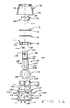
- Figure 1A is an exploded sectional view of an improved ball joint of the present invention
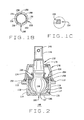
- Figure 1B is a top plan view of an annular upper metal split bearing component present in Fig. 1A ;
- Figure 1C is an enlargement of a portion of Fig. 1A , illustrating a cover plate orientation
- Figure 2 is an assembled sectional view of the ball joint of Fig. 1A .
- a metal housing 102 within which the various internal components of the movable joint 100 are enclosed, is generally cylindrical, with a central bore 104 defining a side wall having a closed lower end 106 and an open upper end 108.
- a lubrication or wear indicator passage 109 may be axially disposed in the closed lower end 106, providing access to the central bore 104 after assembly of the movable joint 100.
- the exterior surface 110 of housing 102 may follow the general contour of the central bore 104. In the embodiment illustrated, the exterior surface 110 further includes an annular flange 112 and a annular groove 114.
- the annular flange 112 and annular groove 114 are configured for attachment of movable joint 100 to other components (not shown). As may be appreciated, the annular flange 112 and annular grove 114 may be adapted for other specific kinds of installations employing threads or other connectors (not shown).
- the central bore 104 of the housing 102 is generally cylindrical having a radius R1, and preferably Includes truncated conical portion 118 adjacent the closed lower end 106.
- An upper bearing portion 120 of the central bore 104 is preferably provided with an increased radial dimension of R2, sized to receive a bearing component.
- a closure portion 122 of the central bore 104, adjacent the open upper end 108 is preferably provided with an increased radial dimension of R3, such that R1 ⁇ R2 ⁇ R3.
- the closure portion 122 corresponds with a reduced-thickness deformable portion 124 of the housing 102 configured for swaging or rolling in a radially inward direction to enclose components within the central bore 104 after assembly.
- a lower bearing 126 sized for an interference fit within the central bore 102 and truncated conical portion 118 is seated against the closed lower end 106.
- the lower bearing 126 is formed from metal, such as a sintered alloy, and includes an inner hemispherical surface 128 axially aligned with a vertical axis VA of the housing, and sized to receive a ball portion 130 of a metal movable stud member 132.
- the metal lower bearing 126 preferably includes one or more slots or grooves 134 disposed in the inner hemispherical surface 128.
- the metal lower bearing 126 further includes an axial lubricant passage 137, aligned with the lubrication or wear indicator passage 109, through which lubricant can be delivered to the bearing surfaces.
- the movable stud member 132 consists of the spherical head portion 130, and an elongated shank portion 138.
- the shank portion 138 may include a reduced diameter neck portion 140 upon which the head portion 130 is formed, one or more constant radius segments 142, and one or more tapered segments 144.
- the shank portion 138 may further include one or more features designed to facilitate a connection to other components (not shown) which may include, but are not limited to, threads 146 and one or more bores 148.
- the remaining components of the movable joint 100 are installed. These include an annular metal upper bearing 150 configured to seat concentrically about the movable stud member 132, against the head portion 130 opposite from the lower metal bearing 126, a Belleville washer 152, and an annular cover plate 154.
- the annular upper metal bearing 150 seats within the upper bearing portion 120 of the central bore 104, and provides an inner hemispherical wear surface 156 for the top and sides of the movable stud member head portion 130.
- the annular upper metal bearing 150 includes one or more lubrication slots 158, and a split 160 extending from the inner surface 156 to an exterior surface 162.
- the split 160 permits the annular upper metal bearing 150 to fully engage the inner surface of the central bore 104 and the head portion 130 simultaneously, limiting movement of the movable stud member 132 when loaded in axial and radial directions.
- the upper metal bearing 150 is preferably sized to move axially within the central bore 104, providing a constant wear surface 156 for the head portion 130, and providing axial and radial support during normal wear of the internal components of the movable joint 100.
- the Belleville washer 152 Prior to installing the cover plate 154 in the central bore 104, the Belleville washer 152 is disposed about the movable stud member 132, and seated on an upper surface 164 of the annular upper metal bearing 150.
- the Belleville washer 152 or washer spring is configured to provide a preload on the assembled components of the movable joint 100, and to establish a desired torque during assembly thereof. After assembly, the load provided by the Belleville washer 152 maintains the simultaneous contact between the upper metal bearing 150, the head portion 130, and the inner surface 120 of the central bore 104.
- the annular cover plate 154 is disposed about the movable stud member 132, and positioned within the central bore 104.
- the reduced-thickness deformable portion 124 of the housing 102 is then swaged or rolled in a radially inward direction to capture the cover plate 154 and enclose components within the central bore 104.
- the Belleville washer 152 is compressed between the cover plate 154 and the upper surface 164 of the upper metal bearing 150, establishing the desired preload force on the housing internal components.
- the cover plate 154 includes a chamfered inner surface 166. The surface 166 provides clearance for the movable stud member 132 during articulation within the housing 102.
- a restrictor 168 and a dust cover 170 may optionally be installed about the movable stud member 132.
- the restrictor 168 consists of a tubular body 171 having an annular region 172 of increased thickness adjacent an upper end 174.
- the annular region 172 and body 174 of the restrictor 168 act to limit the range of articulation of the stud member 132 by contacting the swaged or rolled deformation portion 124 of the housing 102.
- the dust cover 170 is preferably formed from a flexible rubber or other elastomeric material, and is secured to the exterior of the housing 102 by a snap-ring 176 disposed within the dust cover itself, or other conventional retaining member.
- the movable stud member 132 passes through a fitted opening 178 in the top of the dust cover 170, exposing a portion of the stud member 132 for coupling to other components (not shown), such as a vehicle suspension.
- the stud 132 may include a hemispherical or cylindrical head, or the cylindrical body may include threads 146, bores as at 148, or grooves for attachment of external components (not shown).
Landscapes
- Engineering & Computer Science (AREA)
- General Engineering & Computer Science (AREA)
- Mechanical Engineering (AREA)
- Pivots And Pivotal Connections (AREA)
Claims (10)
- Bewegliches Gelenk, umfassend ein Metallgehäuse (102) mit einer Seitenwand, die ein mittiges Loch (104) mit einem geschlossenen Ende (106) und einem offenen Ende (108) definiert, ein unteres Lager (126), das innerhalb des mittigen Lochs (104) angrenzend an das geschlossene Ende (106) angeordnet ist, ein metallisches bewegliches Element (132) mit einem Kopfendteil (130), der in dem mittigen Loch (104) angeordnet ist und einem Schaftteil (138), der sich von dem Kopfendteil (130) erstreckt, wobei der Kopfendteil (130) mit dem unteren Lager (126) in dem mittigen Loch (104) in Eingriff steht, wobei der Schaftteil (138) zumindest teilweise außerhalb des mittigen Lochs (104) angeordnet ist,
ein ringförmiges metallisches oberes Lager (150), das um das bewegliche Element (132) innerhalb des mittigen Lochs (104) angrenzend an das offene Ende (108) angeordnet ist, wobei das obere Lager (150) eine innere Oberfläche (156) aufweist, die mit dem Kopfendteil (130) in direktem Metall-auf-Metall-Gleitkontakt in Eingriff steht, und eine äußere Oberfläche, die mit der Seitenwand in Eingriff steht, eine ringförmige Abdeckplatte (154), die um das bewegliche Element (132) angeordnet ist und innerhalb des mittigen Lochs (104) angrenzend an das offene Ende (108) fixiert ist, und ein Federelement (152), das zwischen der ringförmigen Abdeckplatte (154) und einer oberen Oberfläche (164) des ringförmigen metallischen oberen Lagers (150) komprimiert ist,
dadurch gekennzeichnet, dass
das untere Lager (126) ebenfalls aus Metall gefertigt ist und das obere Lager (150) ein Spaltsegment (160) aufweist, das sich von der inneren Oberfläche (156) zu der äußeren Oberfläche erstreckt,
und dass das Metallgehäuse (102) eine axiale Schmieröffnung (109) aufweist, angeordnet in dem geschlossenen Ende (106) des mittigen Lochs (104), wobei das metallische untere Lager (126) einen Schmierschlitz (137) aufweist, der im allgemeinen axial mit der mittigen Schmieröffnung (109) in dem Metallgehäuse (102) ausgerichtet ist, um einen gemeinsamen Schmierdurchgang bereitzustellen, und dass das Kopfendteil (130) weiter einen flachen Bereich direkt gegenüber dem Schmierschlitz (137) des metallischen unteren Lagers (126) aufweist. - Bewegliches Gelenk nach Anspruch 1, wobei die ringförmige Abdeckplatte (154) und das Federelement (152) aus Metall ausgebildet sind.
- Bewegliches Gelenk nach Anspruch 1 oder 2, wobei das Federelement (152) so ausgelegt ist, dass es eine axiale Vorspannkraft auf das ringförmige metallische obere Lager (150) in Richtung des geschlossenen Endes (106) des mittigen Lochs (104) ausübt; und
wobei das ringförmige metallische obere Lager (150) so ausgelegt ist, dass es gleichzeitig mit der Seitenwand und mit dem Kopfendteil (130) in Eingriff steht. - Bewegliches Gelenk nach Anspruch 1, 2 oder 3, wobei das ringförmige metallische obere Lager (150) axial innerhalb des mittigen Lochs (104) verschiebbar ist.
- Bewegliches Gelenk nach Anspruch 1, wobei das metallische untere Lager (126) in dem mittigen Loch (104) durch eine Presspassung gehalten wird.
- Bewegliches Gelenk nach einem der vorherigen Ansprüche, weiter umfassend eine Staubmanschettenblende (168), die um den Schaftteil (138) herum angeordnet ist.
- Bewegliches Gelenk nach einem der vorhergehenden Ansprüche, weiter umfassend eine flexible Staubabdeckung (170), die zwischen das Gehäuse (102) und den Schaftteil (138) des beweglichen Elements (132) gekoppelt ist.
- Bewegliches Gelenk nach einem der vorhergehenden Ansprüche, wobei das ringförmige metallische obere Lager (150) mindestens einen Schmierschlitz (158)
einschließt, der auf einer inneren Lageroberfläche (156) angeordnet ist. - Bewegliches Gelenk nach einem der vorhergehenden Ansprüche, wobei das Gehäuse (102) einen verformbaren ringförmigen Bereich (124) angrenzend an das obere Ende (108) des mittigen Lochs (104) umfasst, wobei der verformbare ringförmige Bereich (124) zu einer radial nach innen gerichteten Verformung angepasst ist, um die ringförmige Abdeckplatte (154) innerhalb des mittigen Lochs (104) zu fixieren.
- Bewegliches Gelenk nach einem der vorhergehenden Ansprüche, wobei die ringförmige Abdeckplatte eine abgeschrägte innere Oberfläche (166) umfasst, die dazu eingerichtet ist, eine Gelenkbewegung des beweglichen Elements (132) einzuschränken.
Applications Claiming Priority (1)
| Application Number | Priority Date | Filing Date | Title |
|---|---|---|---|
| PCT/US2005/011903 WO2006110133A1 (en) | 2005-04-08 | 2005-04-08 | Metal split bearing compression load ball joint |
Publications (3)
| Publication Number | Publication Date |
|---|---|
| EP1866552A1 EP1866552A1 (de) | 2007-12-19 |
| EP1866552A4 EP1866552A4 (de) | 2008-05-07 |
| EP1866552B1 true EP1866552B1 (de) | 2010-03-17 |
Family
ID=37087320
Family Applications (1)
| Application Number | Title | Priority Date | Filing Date |
|---|---|---|---|
| EP05735422A Expired - Lifetime EP1866552B1 (de) | 2005-04-08 | 2005-04-08 | Drucklastkugelgelenk mit geteiltem metalllager |
Country Status (7)
| Country | Link |
|---|---|
| EP (1) | EP1866552B1 (de) |
| JP (1) | JP4741655B2 (de) |
| CN (1) | CN101175925B (de) |
| CA (1) | CA2604121A1 (de) |
| DE (1) | DE602005020067D1 (de) |
| MX (1) | MX2007012456A (de) |
| WO (1) | WO2006110133A1 (de) |
Cited By (2)
| Publication number | Priority date | Publication date | Assignee | Title |
|---|---|---|---|---|
| WO2016089819A1 (en) * | 2014-12-03 | 2016-06-09 | Federal-Mogul Motorparts Corporation | Ball joint assembly |
| TWI721869B (zh) * | 2020-04-21 | 2021-03-11 | 和碩聯合科技股份有限公司 | 萬向接頭組件 |
Families Citing this family (16)
| Publication number | Priority date | Publication date | Assignee | Title |
|---|---|---|---|---|
| US8747012B2 (en) * | 2008-03-07 | 2014-06-10 | Federal-Mogul Corporation | Tie rod end with friction reducing coating |
| US7862250B2 (en) | 2008-03-13 | 2011-01-04 | Disa Automotive, Inc. | Dust boot assemblies and apparatus for providing grease relief for a dust boot |
| DE102011076167A1 (de) * | 2011-05-20 | 2012-11-22 | Robert Bosch Gmbh | Gelenklager |
| DE102011111842B4 (de) * | 2011-08-27 | 2013-04-04 | Audi Ag | Kugelgelenk |
| EP2976538B1 (de) | 2013-03-21 | 2018-10-10 | Reell Precision Manufacturing Corporation | Mehrachsige kugelscharnierklammer |
| DE102015103463A1 (de) * | 2015-03-10 | 2016-09-15 | Hilite Germany Gmbh | Kugellager, insbesondere Pleuelkugellager, sowie Pleuel mit einem Kugellager |
| JP2018534498A (ja) * | 2015-10-29 | 2018-11-22 | ディー−ボックス テクノロジーズ インコーポレイテッド | 運動シミュレータの継手アセンブリ |
| US10544825B2 (en) * | 2015-11-10 | 2020-01-28 | Federal-Mogul Motorparts Llc | Socket assembly |
| US10371195B2 (en) * | 2016-06-01 | 2019-08-06 | Federal-Mogul Motorparts Llc | Socket assembly and method of making a socket assembly |
| CN106356794B (zh) * | 2016-10-22 | 2019-08-02 | 诸暨市申嘉机械科技有限公司 | 水下脐带缆保护装置 |
| US11396906B2 (en) * | 2018-07-18 | 2022-07-26 | Federal-Mogul Motorparts, LLC | Ball socket assembly with a preload bearing |
| CN108869528A (zh) * | 2018-08-22 | 2018-11-23 | 株洲季元科技有限责任公司 | 一种机车车辆抗侧滚扭杆装置球铰关节密封结构 |
| CN109058311B (zh) * | 2018-09-07 | 2024-08-06 | 河北金菱尔特传动科技股份有限公司 | 方杆球万向联轴器 |
| CN109026988A (zh) * | 2018-10-08 | 2018-12-18 | 常州液压成套设备厂有限公司 | 调心推力轴承组件 |
| US11542981B2 (en) * | 2019-03-08 | 2023-01-03 | Federal-Mogul Motorparts Llc | Socket assembly and method of making a socket assembly |
| CN116877567B (zh) * | 2023-06-20 | 2025-12-02 | 中山市图胜图镜业有限公司 | 一种可调节松紧的万向连接器及一种化妆镜 |
Family Cites Families (16)
| Publication number | Priority date | Publication date | Assignee | Title |
|---|---|---|---|---|
| US2274420A (en) | 1941-02-12 | 1942-02-24 | Katcher Morris | Knuckle joint |
| US2553743A (en) * | 1946-09-13 | 1951-05-22 | Thompson Prod Inc | Ball joint |
| US2635906A (en) * | 1949-07-21 | 1953-04-21 | Thompson Prod Inc | Ball joint |
| GB929873A (en) * | 1959-03-06 | 1963-06-26 | Quinton Hazell Holdings Ltd | A new or improved ball joint |
| US3128110A (en) * | 1961-05-03 | 1964-04-07 | Thompson Ramo Wooldridge Inc | Ball joint |
| US3103370A (en) * | 1962-04-18 | 1963-09-10 | Krizman Mfg Co Inc | Front wheel suspension |
| US3951557A (en) | 1972-07-25 | 1976-04-20 | Trw Inc. | Dual seat ball and socket joint |
| JPS53140870U (de) * | 1977-04-13 | 1978-11-07 | ||
| JPS5519823U (de) * | 1978-07-24 | 1980-02-07 | ||
| JPS60125409A (ja) * | 1983-11-15 | 1985-07-04 | テーエルヴエー・エーレンライヒ・ゲゼルシヤフト・ミツト・ベシユレンクテル・ハフトウング・ウント・コンパニー・コマンデイートゲゼルシヤフト | 玉継手 |
| DE3602917C1 (de) * | 1986-01-31 | 1987-07-30 | Trw Ehrenreich Gmbh | Kugelgelenk |
| DE3816564A1 (de) * | 1988-05-14 | 1989-11-23 | Trw Ehrenreich Gmbh | Kugelgelenk |
| US4871276A (en) * | 1988-11-21 | 1989-10-03 | Moog Automotive, Inc. | Preloaded joint device |
| US5112153A (en) * | 1990-07-17 | 1992-05-12 | Maremont Corporation | End connector assembly with ball held captive in socket bearing and shell housing and method of assembly |
| US5772337A (en) * | 1997-05-01 | 1998-06-30 | Dana Corporation | Polywedge bearing for use with ball and socket |
| US5997208A (en) * | 1998-06-02 | 1999-12-07 | Trw Inc. | Adjustment for a ball joint assembly |
-
2005
- 2005-04-08 CA CA002604121A patent/CA2604121A1/en not_active Abandoned
- 2005-04-08 CN CN2005800497564A patent/CN101175925B/zh not_active Expired - Lifetime
- 2005-04-08 WO PCT/US2005/011903 patent/WO2006110133A1/en not_active Ceased
- 2005-04-08 DE DE602005020067T patent/DE602005020067D1/de not_active Expired - Lifetime
- 2005-04-08 EP EP05735422A patent/EP1866552B1/de not_active Expired - Lifetime
- 2005-04-08 JP JP2008505276A patent/JP4741655B2/ja not_active Expired - Fee Related
- 2005-04-08 MX MX2007012456A patent/MX2007012456A/es active IP Right Grant
Cited By (2)
| Publication number | Priority date | Publication date | Assignee | Title |
|---|---|---|---|---|
| WO2016089819A1 (en) * | 2014-12-03 | 2016-06-09 | Federal-Mogul Motorparts Corporation | Ball joint assembly |
| TWI721869B (zh) * | 2020-04-21 | 2021-03-11 | 和碩聯合科技股份有限公司 | 萬向接頭組件 |
Also Published As
| Publication number | Publication date |
|---|---|
| CN101175925A (zh) | 2008-05-07 |
| CA2604121A1 (en) | 2006-10-19 |
| JP4741655B2 (ja) | 2011-08-03 |
| EP1866552A4 (de) | 2008-05-07 |
| WO2006110133A1 (en) | 2006-10-19 |
| DE602005020067D1 (de) | 2010-04-29 |
| MX2007012456A (es) | 2007-12-13 |
| EP1866552A1 (de) | 2007-12-19 |
| CN101175925B (zh) | 2011-03-30 |
| JP2008536065A (ja) | 2008-09-04 |
Similar Documents
| Publication | Publication Date | Title |
|---|---|---|
| US8047739B2 (en) | Metal split bearing compression load ball joint | |
| EP1866552B1 (de) | Drucklastkugelgelenk mit geteiltem metalllager | |
| US11209043B2 (en) | Socket assembly and method of making a socket assembly | |
| US6439794B2 (en) | Compliant pivot socket for automotive steering | |
| US10294983B2 (en) | Socket assembly and method of making a socket assembly | |
| US6413003B1 (en) | Compliant pivot socket for automotive steering | |
| US7344311B2 (en) | Suspension joint bearing | |
| CN110637166B (zh) | 球窝接头组件 | |
| CN107250578A (zh) | 球形接头组件 | |
| EP3430279B1 (de) | Buchsenanordnung und verfahren zur herstellung einer buchsenanordnung | |
| US10895280B2 (en) | Socket assembly and method of making | |
| US6676325B2 (en) | Automotive steering compliant pivot socket with tapered head | |
| CA2967299C (en) | Snap-in bearing for automotive ball joint | |
| CN112041572B (zh) | 压缩加载的球窝组件 | |
| US10584737B2 (en) | Compression loaded ball socket assembly | |
| US20080304902A1 (en) | Ball joint |
Legal Events
| Date | Code | Title | Description |
|---|---|---|---|
| PUAI | Public reference made under article 153(3) epc to a published international application that has entered the european phase |
Free format text: ORIGINAL CODE: 0009012 |
|
| 17P | Request for examination filed |
Effective date: 20071019 |
|
| AK | Designated contracting states |
Kind code of ref document: A1 Designated state(s): DE ES FR GB IT |
|
| A4 | Supplementary search report drawn up and despatched |
Effective date: 20080409 |
|
| RIC1 | Information provided on ipc code assigned before grant |
Ipc: F16C 11/06 20060101AFI20080403BHEP |
|
| RBV | Designated contracting states (corrected) |
Designated state(s): DE ES FR GB IT |
|
| DAX | Request for extension of the european patent (deleted) | ||
| 17Q | First examination report despatched |
Effective date: 20080808 |
|
| GRAP | Despatch of communication of intention to grant a patent |
Free format text: ORIGINAL CODE: EPIDOSNIGR1 |
|
| GRAS | Grant fee paid |
Free format text: ORIGINAL CODE: EPIDOSNIGR3 |
|
| GRAA | (expected) grant |
Free format text: ORIGINAL CODE: 0009210 |
|
| AK | Designated contracting states |
Kind code of ref document: B1 Designated state(s): DE ES FR GB IT |
|
| REG | Reference to a national code |
Ref country code: GB Ref legal event code: FG4D |
|
| REF | Corresponds to: |
Ref document number: 602005020067 Country of ref document: DE Date of ref document: 20100429 Kind code of ref document: P |
|
| PG25 | Lapsed in a contracting state [announced via postgrant information from national office to epo] |
Ref country code: ES Free format text: LAPSE BECAUSE OF FAILURE TO SUBMIT A TRANSLATION OF THE DESCRIPTION OR TO PAY THE FEE WITHIN THE PRESCRIBED TIME-LIMIT Effective date: 20100628 |
|
| PLBE | No opposition filed within time limit |
Free format text: ORIGINAL CODE: 0009261 |
|
| STAA | Information on the status of an ep patent application or granted ep patent |
Free format text: STATUS: NO OPPOSITION FILED WITHIN TIME LIMIT |
|
| 26N | No opposition filed |
Effective date: 20101220 |
|
| GBPC | Gb: european patent ceased through non-payment of renewal fee |
Effective date: 20100617 |
|
| PG25 | Lapsed in a contracting state [announced via postgrant information from national office to epo] |
Ref country code: GB Free format text: LAPSE BECAUSE OF NON-PAYMENT OF DUE FEES Effective date: 20100617 |
|
| REG | Reference to a national code |
Ref country code: FR Ref legal event code: PLFP Year of fee payment: 11 |
|
| REG | Reference to a national code |
Ref country code: FR Ref legal event code: PLFP Year of fee payment: 12 |
|
| REG | Reference to a national code |
Ref country code: FR Ref legal event code: PLFP Year of fee payment: 13 |
|
| REG | Reference to a national code |
Ref country code: FR Ref legal event code: PLFP Year of fee payment: 14 |
|
| PGFP | Annual fee paid to national office [announced via postgrant information from national office to epo] |
Ref country code: FR Payment date: 20200319 Year of fee payment: 16 |
|
| PGFP | Annual fee paid to national office [announced via postgrant information from national office to epo] |
Ref country code: DE Payment date: 20200319 Year of fee payment: 16 |
|
| PGFP | Annual fee paid to national office [announced via postgrant information from national office to epo] |
Ref country code: IT Payment date: 20200318 Year of fee payment: 16 |
|
| REG | Reference to a national code |
Ref country code: DE Ref legal event code: R119 Ref document number: 602005020067 Country of ref document: DE |
|
| PG25 | Lapsed in a contracting state [announced via postgrant information from national office to epo] |
Ref country code: FR Free format text: LAPSE BECAUSE OF NON-PAYMENT OF DUE FEES Effective date: 20210430 Ref country code: DE Free format text: LAPSE BECAUSE OF NON-PAYMENT OF DUE FEES Effective date: 20211103 |
|
| PG25 | Lapsed in a contracting state [announced via postgrant information from national office to epo] |
Ref country code: IT Free format text: LAPSE BECAUSE OF NON-PAYMENT OF DUE FEES Effective date: 20200408 |
|
| PG25 | Lapsed in a contracting state [announced via postgrant information from national office to epo] |
Ref country code: IT Free format text: LAPSE BECAUSE OF NON-PAYMENT OF DUE FEES Effective date: 20210408 |