EP1866552B1 - Metal split bearing compression load ball joint - Google Patents
Metal split bearing compression load ball joint Download PDFInfo
- Publication number
- EP1866552B1 EP1866552B1 EP05735422A EP05735422A EP1866552B1 EP 1866552 B1 EP1866552 B1 EP 1866552B1 EP 05735422 A EP05735422 A EP 05735422A EP 05735422 A EP05735422 A EP 05735422A EP 1866552 B1 EP1866552 B1 EP 1866552B1
- Authority
- EP
- European Patent Office
- Prior art keywords
- metal
- central bore
- bearing
- housing
- annular
- Prior art date
- Legal status (The legal status is an assumption and is not a legal conclusion. Google has not performed a legal analysis and makes no representation as to the accuracy of the status listed.)
- Expired - Lifetime
Links
Images
Classifications
-
- F—MECHANICAL ENGINEERING; LIGHTING; HEATING; WEAPONS; BLASTING
- F16—ENGINEERING ELEMENTS AND UNITS; GENERAL MEASURES FOR PRODUCING AND MAINTAINING EFFECTIVE FUNCTIONING OF MACHINES OR INSTALLATIONS; THERMAL INSULATION IN GENERAL
- F16C—SHAFTS; FLEXIBLE SHAFTS; ELEMENTS OR CRANKSHAFT MECHANISMS; ROTARY BODIES OTHER THAN GEARING ELEMENTS; BEARINGS
- F16C11/00—Pivots; Pivotal connections
- F16C11/04—Pivotal connections
- F16C11/06—Ball-joints; Other joints having more than one degree of angular freedom, i.e. universal joints
- F16C11/0685—Manufacture of ball-joints and parts thereof, e.g. assembly of ball-joints
- F16C11/069—Manufacture of ball-joints and parts thereof, e.g. assembly of ball-joints with at least one separate part to retain the ball member in the socket; Quick-release systems
-
- F—MECHANICAL ENGINEERING; LIGHTING; HEATING; WEAPONS; BLASTING
- F16—ENGINEERING ELEMENTS AND UNITS; GENERAL MEASURES FOR PRODUCING AND MAINTAINING EFFECTIVE FUNCTIONING OF MACHINES OR INSTALLATIONS; THERMAL INSULATION IN GENERAL
- F16C—SHAFTS; FLEXIBLE SHAFTS; ELEMENTS OR CRANKSHAFT MECHANISMS; ROTARY BODIES OTHER THAN GEARING ELEMENTS; BEARINGS
- F16C11/00—Pivots; Pivotal connections
- F16C11/04—Pivotal connections
- F16C11/06—Ball-joints; Other joints having more than one degree of angular freedom, i.e. universal joints
- F16C11/0619—Ball-joints; Other joints having more than one degree of angular freedom, i.e. universal joints the female part comprising a blind socket receiving the male part
- F16C11/0623—Construction or details of the socket member
- F16C11/0628—Construction or details of the socket member with linings
-
- F—MECHANICAL ENGINEERING; LIGHTING; HEATING; WEAPONS; BLASTING
- F16—ENGINEERING ELEMENTS AND UNITS; GENERAL MEASURES FOR PRODUCING AND MAINTAINING EFFECTIVE FUNCTIONING OF MACHINES OR INSTALLATIONS; THERMAL INSULATION IN GENERAL
- F16C—SHAFTS; FLEXIBLE SHAFTS; ELEMENTS OR CRANKSHAFT MECHANISMS; ROTARY BODIES OTHER THAN GEARING ELEMENTS; BEARINGS
- F16C11/00—Pivots; Pivotal connections
- F16C11/04—Pivotal connections
- F16C11/06—Ball-joints; Other joints having more than one degree of angular freedom, i.e. universal joints
- F16C11/0619—Ball-joints; Other joints having more than one degree of angular freedom, i.e. universal joints the female part comprising a blind socket receiving the male part
- F16C11/0623—Construction or details of the socket member
- F16C11/0647—Special features relating to adjustment for wear or play; Wear indicators
-
- F—MECHANICAL ENGINEERING; LIGHTING; HEATING; WEAPONS; BLASTING
- F16—ENGINEERING ELEMENTS AND UNITS; GENERAL MEASURES FOR PRODUCING AND MAINTAINING EFFECTIVE FUNCTIONING OF MACHINES OR INSTALLATIONS; THERMAL INSULATION IN GENERAL
- F16C—SHAFTS; FLEXIBLE SHAFTS; ELEMENTS OR CRANKSHAFT MECHANISMS; ROTARY BODIES OTHER THAN GEARING ELEMENTS; BEARINGS
- F16C2326/00—Articles relating to transporting
- F16C2326/01—Parts of vehicles in general
- F16C2326/05—Vehicle suspensions, e.g. bearings, pivots or connecting rods used therein
-
- F—MECHANICAL ENGINEERING; LIGHTING; HEATING; WEAPONS; BLASTING
- F16—ENGINEERING ELEMENTS AND UNITS; GENERAL MEASURES FOR PRODUCING AND MAINTAINING EFFECTIVE FUNCTIONING OF MACHINES OR INSTALLATIONS; THERMAL INSULATION IN GENERAL
- F16C—SHAFTS; FLEXIBLE SHAFTS; ELEMENTS OR CRANKSHAFT MECHANISMS; ROTARY BODIES OTHER THAN GEARING ELEMENTS; BEARINGS
- F16C2326/00—Articles relating to transporting
- F16C2326/20—Land vehicles
- F16C2326/24—Steering systems, e.g. steering rods or columns
Definitions
- the present invention relates to ball joint bearings, and in particular, to an improved all metal compression load ball joint utilizing a split upper bearing configured to provide a bearing surface for the top and sides of a ball stud, and to allow full engagement of the bearing with the housing and the stud simultaneously.
- Conventional ball joints, and other movable sockets are used, for example, in automotive steering and suspension applications, and can be divided into two categories.
- the first category is for use in follower and tension load applications in which the stud member of the ball joint experiences axial tension loads
- the second category is for use in compression load applications in which the stud member of the ball joint experiences axial compression loads. Due to the different axial loads on the stud member, different ball joint designs are required for each category, which are generally not interchangeable.
- ball and socket joints comprise a cylindrical housing having a cylindrical internal surface and an opening through which the shank portion of a stud member extends.
- a ball end portion of the stud member is contained in the housing, with one or more bearing members supporting the ball end portion within the housing.
- the bearing members are composed of a synthetic resin, such as a polymer or elastomer, or a sintered alloy.
- tension load ball joints such as the M2 Technology chassis parts available from the Moog Chassis Parts division of Federal Mogul Corporation, utilize two openings at opposite ends of the housing. After the components are installed therein, one opening is closed by means of a cover-plate, spun, swaged, or welded in place, and the stud member extends outward through the opposite opening. Once secured in place, the cover-plate presses on the bearing members either directly or indirectly through a resilient rubber intermediate component.
- US 3,951,557 discloses a similar tension ball joint where a split bearing of plastics material is urged into contact with the ball by the action of a spring which is retained in the opening by a cover plate.
- compression load ball joint housings such as shown in U.S. Patent No. 6,010,271 to Jackson et al ., have only a single opening through which all the components are installed during assembly, and through which the stud member protrudes.
- These components include a compression spring, a polymeric lower bearing, the stud member, and a metal upper bearing.
- US 2,274,420 discloses a similar compression ball joint having the features specified in the preamble of claim 1.
- the lower bearing in this case is a non-metal anti-friction liner.
- ball joints and movable sockets may be utilized as load carrying members in numerous mechanical systems, including automotive vehicle suspension and steering systems.
- Movable sockets or ball-joints employed in these applications are subjected to various operating conditions, and may be required to carry substantial loads.
- wear develops, particularly in polymeric bearings the performance of the movable socket or ball-joint rapidly degrades and, in the case of automotive applications, may result in erratic steering or excessive looseness and play in the vehicle suspension system.
- the present invention provides an improved compression load ball joint assembly as specified in claim 1.
- the lower metal bearing is retained against movement by an interference fit between the outer side surface of the lower bearing and the inner side surface and inner end surface of the housing.
- the upper metal split bearing is enclosed by the housing within the internal cylindrical chamber, concentric with the movable stud member.
- the upper metal split bearing is disposed opposite the lower metal bearing to engage the movable stud member and the housing simultaneously.
- the split upper bearing is configured to slide within the housing to provide for a constant wear surface against the movable stud member.
- the spring member is preferably a Belleville washer concentrically disposed about the movable stud member to provide an axial load on the split upper bearing.
- the lower bearing, upper split bearing, Belleville washer, and movable stud member are contained within the housing by the cover plate which is concentrically disposed about the movable stud member and secured within the open end of the housing.
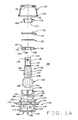
- Figure 1A is an exploded sectional view of an improved ball joint of the present invention
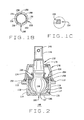
- Figure 1B is a top plan view of an annular upper metal split bearing component present in Fig. 1A ;
- Figure 1C is an enlargement of a portion of Fig. 1A , illustrating a cover plate orientation
- Figure 2 is an assembled sectional view of the ball joint of Fig. 1A .
- a metal housing 102 within which the various internal components of the movable joint 100 are enclosed, is generally cylindrical, with a central bore 104 defining a side wall having a closed lower end 106 and an open upper end 108.
- a lubrication or wear indicator passage 109 may be axially disposed in the closed lower end 106, providing access to the central bore 104 after assembly of the movable joint 100.
- the exterior surface 110 of housing 102 may follow the general contour of the central bore 104. In the embodiment illustrated, the exterior surface 110 further includes an annular flange 112 and a annular groove 114.
- the annular flange 112 and annular groove 114 are configured for attachment of movable joint 100 to other components (not shown). As may be appreciated, the annular flange 112 and annular grove 114 may be adapted for other specific kinds of installations employing threads or other connectors (not shown).
- the central bore 104 of the housing 102 is generally cylindrical having a radius R1, and preferably Includes truncated conical portion 118 adjacent the closed lower end 106.
- An upper bearing portion 120 of the central bore 104 is preferably provided with an increased radial dimension of R2, sized to receive a bearing component.
- a closure portion 122 of the central bore 104, adjacent the open upper end 108 is preferably provided with an increased radial dimension of R3, such that R1 ⁇ R2 ⁇ R3.
- the closure portion 122 corresponds with a reduced-thickness deformable portion 124 of the housing 102 configured for swaging or rolling in a radially inward direction to enclose components within the central bore 104 after assembly.
- a lower bearing 126 sized for an interference fit within the central bore 102 and truncated conical portion 118 is seated against the closed lower end 106.
- the lower bearing 126 is formed from metal, such as a sintered alloy, and includes an inner hemispherical surface 128 axially aligned with a vertical axis VA of the housing, and sized to receive a ball portion 130 of a metal movable stud member 132.
- the metal lower bearing 126 preferably includes one or more slots or grooves 134 disposed in the inner hemispherical surface 128.
- the metal lower bearing 126 further includes an axial lubricant passage 137, aligned with the lubrication or wear indicator passage 109, through which lubricant can be delivered to the bearing surfaces.
- the movable stud member 132 consists of the spherical head portion 130, and an elongated shank portion 138.
- the shank portion 138 may include a reduced diameter neck portion 140 upon which the head portion 130 is formed, one or more constant radius segments 142, and one or more tapered segments 144.
- the shank portion 138 may further include one or more features designed to facilitate a connection to other components (not shown) which may include, but are not limited to, threads 146 and one or more bores 148.
- the remaining components of the movable joint 100 are installed. These include an annular metal upper bearing 150 configured to seat concentrically about the movable stud member 132, against the head portion 130 opposite from the lower metal bearing 126, a Belleville washer 152, and an annular cover plate 154.
- the annular upper metal bearing 150 seats within the upper bearing portion 120 of the central bore 104, and provides an inner hemispherical wear surface 156 for the top and sides of the movable stud member head portion 130.
- the annular upper metal bearing 150 includes one or more lubrication slots 158, and a split 160 extending from the inner surface 156 to an exterior surface 162.
- the split 160 permits the annular upper metal bearing 150 to fully engage the inner surface of the central bore 104 and the head portion 130 simultaneously, limiting movement of the movable stud member 132 when loaded in axial and radial directions.
- the upper metal bearing 150 is preferably sized to move axially within the central bore 104, providing a constant wear surface 156 for the head portion 130, and providing axial and radial support during normal wear of the internal components of the movable joint 100.
- the Belleville washer 152 Prior to installing the cover plate 154 in the central bore 104, the Belleville washer 152 is disposed about the movable stud member 132, and seated on an upper surface 164 of the annular upper metal bearing 150.
- the Belleville washer 152 or washer spring is configured to provide a preload on the assembled components of the movable joint 100, and to establish a desired torque during assembly thereof. After assembly, the load provided by the Belleville washer 152 maintains the simultaneous contact between the upper metal bearing 150, the head portion 130, and the inner surface 120 of the central bore 104.
- the annular cover plate 154 is disposed about the movable stud member 132, and positioned within the central bore 104.
- the reduced-thickness deformable portion 124 of the housing 102 is then swaged or rolled in a radially inward direction to capture the cover plate 154 and enclose components within the central bore 104.
- the Belleville washer 152 is compressed between the cover plate 154 and the upper surface 164 of the upper metal bearing 150, establishing the desired preload force on the housing internal components.
- the cover plate 154 includes a chamfered inner surface 166. The surface 166 provides clearance for the movable stud member 132 during articulation within the housing 102.
- a restrictor 168 and a dust cover 170 may optionally be installed about the movable stud member 132.
- the restrictor 168 consists of a tubular body 171 having an annular region 172 of increased thickness adjacent an upper end 174.
- the annular region 172 and body 174 of the restrictor 168 act to limit the range of articulation of the stud member 132 by contacting the swaged or rolled deformation portion 124 of the housing 102.
- the dust cover 170 is preferably formed from a flexible rubber or other elastomeric material, and is secured to the exterior of the housing 102 by a snap-ring 176 disposed within the dust cover itself, or other conventional retaining member.
- the movable stud member 132 passes through a fitted opening 178 in the top of the dust cover 170, exposing a portion of the stud member 132 for coupling to other components (not shown), such as a vehicle suspension.
- the stud 132 may include a hemispherical or cylindrical head, or the cylindrical body may include threads 146, bores as at 148, or grooves for attachment of external components (not shown).
Landscapes
- Engineering & Computer Science (AREA)
- General Engineering & Computer Science (AREA)
- Mechanical Engineering (AREA)
- Pivots And Pivotal Connections (AREA)
Abstract
Description
- The present invention relates to ball joint bearings, and in particular, to an improved all metal compression load ball joint utilizing a split upper bearing configured to provide a bearing surface for the top and sides of a ball stud, and to allow full engagement of the bearing with the housing and the stud simultaneously.
- Conventional ball joints, and other movable sockets are used, for example, in automotive steering and suspension applications, and can be divided into two categories. The first category is for use in follower and tension load applications in which the stud member of the ball joint experiences axial tension loads, while the second category is for use in compression load applications in which the stud member of the ball joint experiences axial compression loads. Due to the different axial loads on the stud member, different ball joint designs are required for each category, which are generally not interchangeable.
- In general, ball and socket joints comprise a cylindrical housing having a cylindrical internal surface and an opening through which the shank portion of a stud member extends. A ball end portion of the stud member is contained in the housing, with one or more bearing members supporting the ball end portion within the housing. Traditionally, the bearing members are composed of a synthetic resin, such as a polymer or elastomer, or a sintered alloy. These components are installed into the housing through an opening, with the ball stud extending outward through an axially disposed opening which may either be the same opening through which the components were installed, or an axially opposite opening. Conventionally, tension load ball joints, such as the M2 Technology chassis parts available from the Moog Chassis Parts division of Federal Mogul Corporation, utilize two openings at opposite ends of the housing. After the components are installed therein, one opening is closed by means of a cover-plate, spun, swaged, or welded in place, and the stud member extends outward through the opposite opening. Once secured in place, the cover-plate presses on the bearing members either directly or indirectly through a resilient rubber intermediate component.
-
US 3,951,557 discloses a similar tension ball joint where a split bearing of plastics material is urged into contact with the ball by the action of a spring which is retained in the opening by a cover plate. - In contrast, compression load ball joint housings, such as shown in
U.S. Patent No. 6,010,271 to Jackson et al ., have only a single opening through which all the components are installed during assembly, and through which the stud member protrudes. These components include a compression spring, a polymeric lower bearing, the stud member, and a metal upper bearing. Once the components are in place, and the stud member shank is protruding from the opening, the peripheral edges of the opening are swaged or rolled to retain the components in place and compressing the spring. -
US 2,274,420 discloses a similar compression ball joint having the features specified in the preamble of claim 1. The lower bearing in this case is a non-metal anti-friction liner. - Once assembled, ball joints and movable sockets may be utilized as load carrying members in numerous mechanical systems, including automotive vehicle suspension and steering systems. Movable sockets or ball-joints employed in these applications are subjected to various operating conditions, and may be required to carry substantial loads. When wear develops, particularly in polymeric bearings, the performance of the movable socket or ball-joint rapidly degrades and, in the case of automotive applications, may result in erratic steering or excessive looseness and play in the vehicle suspension system.
- Accordingly, it is desirable to provide a compression load ball and socket joint having an improved resistance to wear.
- The present invention provides an improved compression load ball joint assembly as specified in claim 1.
- The lower metal bearing is retained against movement by an interference fit between the outer side surface of the lower bearing and the inner side surface and inner end surface of the housing. The upper metal split bearing is enclosed by the housing within the internal cylindrical chamber, concentric with the movable stud member. The upper metal split bearing is disposed opposite the lower metal bearing to engage the movable stud member and the housing simultaneously. The split upper bearing is configured to slide within the housing to provide for a constant wear surface against the movable stud member. The spring member is preferably a Belleville washer concentrically disposed about the movable stud member to provide an axial load on the split upper bearing. The lower bearing, upper split bearing, Belleville washer, and movable stud member are contained within the housing by the cover plate which is concentrically disposed about the movable stud member and secured within the open end of the housing.
- The foregoing and other objects, features, and advantages of the invention as well as presently preferred embodiments thereof will become more apparent from the reading of the following description in connection with the accompanying drawings.
- In the accompanying drawings which form part of the specification:
-
Figure 1A is an exploded sectional view of an improved ball joint of the present invention; -
Figure 1B is a top plan view of an annular upper metal split bearing component present inFig. 1A ; -
Figure 1C is an enlargement of a portion ofFig. 1A , illustrating a cover plate orientation; and -
Figure 2 is an assembled sectional view of the ball joint ofFig. 1A . - Corresponding reference numerals indicate corresponding parts throughout the several figures of the drawings.
- The following detailed description illustrates the invention by way of example and not by way of limitation. The description clearly enables one skilled in the art to make and use the invention, describes several embodiments, adaptations, variations, alternatives, and uses of the invention, including what is presently believed to be the best mode of carrying out the invention.
- Turning to
Figure 1A , amovable joint 100 of the present invention is shown in an exploded view. Ametal housing 102, within which the various internal components of themovable joint 100 are enclosed, is generally cylindrical, with acentral bore 104 defining a side wall having a closedlower end 106 and an openupper end 108. A lubrication orwear indicator passage 109 may be axially disposed in the closedlower end 106, providing access to thecentral bore 104 after assembly of themovable joint 100. Theexterior surface 110 ofhousing 102 may follow the general contour of thecentral bore 104. In the embodiment illustrated, theexterior surface 110 further includes anannular flange 112 and aannular groove 114. Theannular flange 112 andannular groove 114 are configured for attachment ofmovable joint 100 to other components (not shown). As may be appreciated, theannular flange 112 andannular grove 114 may be adapted for other specific kinds of installations employing threads or other connectors (not shown). - The
central bore 104 of thehousing 102 is generally cylindrical having a radius R1, and preferably Includes truncatedconical portion 118 adjacent the closedlower end 106. An upper bearingportion 120 of thecentral bore 104 is preferably provided with an increased radial dimension of R2, sized to receive a bearing component. Finally, aclosure portion 122 of thecentral bore 104, adjacent the openupper end 108 is preferably provided with an increased radial dimension of R3, such that R1 < R2 ≤ R3. Theclosure portion 122 corresponds with a reduced-thicknessdeformable portion 124 of thehousing 102 configured for swaging or rolling in a radially inward direction to enclose components within thecentral bore 104 after assembly. - To assemble the
movable joint 100, alower bearing 126 sized for an interference fit within thecentral bore 102 and truncatedconical portion 118 is seated against the closedlower end 106. Thelower bearing 126 is formed from metal, such as a sintered alloy, and includes an innerhemispherical surface 128 axially aligned with a vertical axis VA of the housing, and sized to receive aball portion 130 of a metalmovable stud member 132. The metal lower bearing 126 preferably includes one or more slots orgrooves 134 disposed in the innerhemispherical surface 128.Slots 134 facilitate a flow of lubricant between the inner hemispherical bearingsurface 128 and anouter surface 136 of theball portion 130. The metallower bearing 126 further includes anaxial lubricant passage 137, aligned with the lubrication orwear indicator passage 109, through which lubricant can be delivered to the bearing surfaces. - As seen in
Figure 1A , themovable stud member 132 consists of thespherical head portion 130, and anelongated shank portion 138. Those of ordinary skill in the art will recognize that the particular shape and configuration of theshank portion 138 may be varied depending upon the particular application for which themovable joint 100 is configured. For example, as shown inFigure 1A , theshank portion 138 may include a reduceddiameter neck portion 140 upon which thehead portion 130 is formed, one or moreconstant radius segments 142, and one or moretapered segments 144. Theshank portion 138 may further include one or more features designed to facilitate a connection to other components (not shown) which may include, but are not limited to,threads 146 and one ormore bores 148. - Once the lower metal bearing 126 and
movable stud member 132 are positioned in thecentral bore 104 during assembly, the remaining components of themovable joint 100 are installed. These include an annular metalupper bearing 150 configured to seat concentrically about themovable stud member 132, against thehead portion 130 opposite from thelower metal bearing 126, aBelleville washer 152, and anannular cover plate 154. - The annular upper metal bearing 150 seats within the
upper bearing portion 120 of thecentral bore 104, and provides an innerhemispherical wear surface 156 for the top and sides of the movable studmember head portion 130. As seen inFigure 1B , the annularupper metal bearing 150 includes one ormore lubrication slots 158, and asplit 160 extending from theinner surface 156 to anexterior surface 162. Thesplit 160 permits the annular upper metal bearing 150 to fully engage the inner surface of thecentral bore 104 and thehead portion 130 simultaneously, limiting movement of themovable stud member 132 when loaded in axial and radial directions. Theupper metal bearing 150 is preferably sized to move axially within thecentral bore 104, providing aconstant wear surface 156 for thehead portion 130, and providing axial and radial support during normal wear of the internal components of themovable joint 100. - Prior to installing the
cover plate 154 in thecentral bore 104, theBelleville washer 152 is disposed about themovable stud member 132, and seated on anupper surface 164 of the annularupper metal bearing 150. TheBelleville washer 152 or washer spring is configured to provide a preload on the assembled components of the movable joint 100, and to establish a desired torque during assembly thereof. After assembly, the load provided by theBelleville washer 152 maintains the simultaneous contact between theupper metal bearing 150, thehead portion 130, and theinner surface 120 of thecentral bore 104. - To complete the assembly of the components within the
housing 102, theannular cover plate 154 is disposed about themovable stud member 132, and positioned within thecentral bore 104. The reduced-thickness deformable portion 124 of thehousing 102 is then swaged or rolled in a radially inward direction to capture thecover plate 154 and enclose components within thecentral bore 104. During the swaging or rolling processes, theBelleville washer 152 is compressed between thecover plate 154 and theupper surface 164 of theupper metal bearing 150, establishing the desired preload force on the housing internal components. Preferably, as shown inFigure 1C , thecover plate 154 includes a chamferedinner surface 166. Thesurface 166 provides clearance for themovable stud member 132 during articulation within thehousing 102. - As illustrated in
Figures 1A and2 , arestrictor 168 and adust cover 170 may optionally be installed about themovable stud member 132. Therestrictor 168 consists of atubular body 171 having anannular region 172 of increased thickness adjacent anupper end 174. When therestrictor 168 is disposed about theneck portion 140 of thestud member 132, theannular region 172 andbody 174 of the restrictor 168 act to limit the range of articulation of thestud member 132 by contacting the swaged or rolleddeformation portion 124 of thehousing 102. - The
dust cover 170 is preferably formed from a flexible rubber or other elastomeric material, and is secured to the exterior of thehousing 102 by a snap-ring 176 disposed within the dust cover itself, or other conventional retaining member. Themovable stud member 132 passes through a fittedopening 178 in the top of thedust cover 170, exposing a portion of thestud member 132 for coupling to other components (not shown), such as a vehicle suspension. - Those skilled in the art will readily recognize that a variety of shapes and configurations for
housing 102 andmovable stud member 132 are possible, together with associated configurations ofbearings stud 132 may include a hemispherical or cylindrical head, or the cylindrical body may includethreads 146, bores as at 148, or grooves for attachment of external components (not shown). - In view of the above, it will be seen that the several objects of the invention are achieved and other advantageous results are obtained. As various changes could be made in the above constructions without departing from the scope of the invention, it is intended that all matter contained in the above description or shown in the accompanying drawings shall be interpreted as illustrative and not in a limiting sense.
Claims (10)
- A movable joint comprising a metal housing (102) having a side wall which defines a central bore (104) having a closed end (106) and an open end (108), a lower bearing (126) disposed within said central bore (104) adjacent said closed end (106), a metal movable member (132) having a head end portion (130) disposed in said central bore (104) and a shank portion (138) extending from said head end portion (130), said head end portion (130) engaging said lower bearing (126) in said central bore (104), said shank portion (138) being at least partially disposed outside of said central bore (104), an annular metal upper bearing (150) disposed about said movable member (132) within said central bore (104) adjacent said open end (108), said upper bearing (150) having an inner surface (156) engaging said head end portion (130) in direct metal-to-metal sliding contact and an outer surface engaging said side wall, an annular cover plate (154) disposed about said movable member (132) and secured within said central bore (104) adjacent said open end (108) and a spring member (152) compressed between said annular cover plate (154) and an upper surface (164) of said annular metal upper bearing (150), characterised in that
said lower bearing (126) is also of metal and said upper bearing (150) has a split segment (160) extending from said inner surface (156) to said outer surface,
and in that said metal housing (102) has an axial lubrication port (109) disposed in said closed end (106) of said central bore (104), said metal lower bearing (126) includes a lubrication slot (137) which is generally axially aligned with said central lubrication port (109) in said metal housing (102) to provide a common lubrication passageway, and said head end portion (130) further includes a flat spot in direct facing opposition to said lubrication slot (137) of said metal lower bearing (126). - A movable joint according to claim 1 wherein said annular cover plate (154) and said spring member (152) are composed of metal.
- A movable joint according to claim 1 or 2 wherein said spring member (152) is configured to exert an axial preload force on said annular metal upper bearing (150) towards said closed end (106) of said central bore (104); and
wherein said annular metal upper bearing (150) is configured to engage said side wall and said head end portion (130) simultaneously. - A movable joint according to claim 1, 2 or 3 wherein said annular metal upper bearing (150) is axially displaceable within said central bore (104).
- A movable joint of claim 1 wherein said metal lower bearing (126) is retained with said central bore (104) by an interference fit.
- A movable joint according to any preceding claim further including a dust boot restrictor (168) disposed about said shank portion (138).
- A movable joint according to any preceding claim further including a flexible dust cover (170) coupled between said housing (102) and said shank portion (138) of said movable member (132).
- A movable joint according to any preceding claim wherein said annular metal upper bearing (150) includes at least one lubrication slot (158) disposed on an inner bearing surface (156).
- A movable joint according to any preceding claim wherein said housing (102) includes a deformable annular region (124) adjacent said open end (108) of said central bore (104), said deformable annular region (124) adapted for radially inward deformation to secure said annular cover plate (154) within said central bore (104).
- A movable joint according to any preceding claim wherein said annular cover plate (154) includes a chamfered inner surface (166) which is configured to restrict articulation of said movable member (132).
Applications Claiming Priority (1)
| Application Number | Priority Date | Filing Date | Title |
|---|---|---|---|
| PCT/US2005/011903 WO2006110133A1 (en) | 2005-04-08 | 2005-04-08 | Metal split bearing compression load ball joint |
Publications (3)
| Publication Number | Publication Date |
|---|---|
| EP1866552A1 EP1866552A1 (en) | 2007-12-19 |
| EP1866552A4 EP1866552A4 (en) | 2008-05-07 |
| EP1866552B1 true EP1866552B1 (en) | 2010-03-17 |
Family
ID=37087320
Family Applications (1)
| Application Number | Title | Priority Date | Filing Date |
|---|---|---|---|
| EP05735422A Expired - Lifetime EP1866552B1 (en) | 2005-04-08 | 2005-04-08 | Metal split bearing compression load ball joint |
Country Status (7)
| Country | Link |
|---|---|
| EP (1) | EP1866552B1 (en) |
| JP (1) | JP4741655B2 (en) |
| CN (1) | CN101175925B (en) |
| CA (1) | CA2604121A1 (en) |
| DE (1) | DE602005020067D1 (en) |
| MX (1) | MX2007012456A (en) |
| WO (1) | WO2006110133A1 (en) |
Cited By (2)
| Publication number | Priority date | Publication date | Assignee | Title |
|---|---|---|---|---|
| WO2016089819A1 (en) * | 2014-12-03 | 2016-06-09 | Federal-Mogul Motorparts Corporation | Ball joint assembly |
| TWI721869B (en) * | 2020-04-21 | 2021-03-11 | 和碩聯合科技股份有限公司 | Universal joint assembly |
Families Citing this family (16)
| Publication number | Priority date | Publication date | Assignee | Title |
|---|---|---|---|---|
| US8747012B2 (en) * | 2008-03-07 | 2014-06-10 | Federal-Mogul Corporation | Tie rod end with friction reducing coating |
| US7862250B2 (en) | 2008-03-13 | 2011-01-04 | Disa Automotive, Inc. | Dust boot assemblies and apparatus for providing grease relief for a dust boot |
| DE102011076167A1 (en) * | 2011-05-20 | 2012-11-22 | Robert Bosch Gmbh | Universal joint bearing for supercharger of internal combustion engine used in motor vehicle, has bearing cup that is provided with concave and partial convex bearing surfaces to bearing head is supported |
| DE102011111842B4 (en) * | 2011-08-27 | 2013-04-04 | Audi Ag | ball joint |
| EP2976538B1 (en) | 2013-03-21 | 2018-10-10 | Reell Precision Manufacturing Corporation | Ball-and-socket multi-axis clip hinge |
| DE102015103463A1 (en) * | 2015-03-10 | 2016-09-15 | Hilite Germany Gmbh | Ball bearings, in particular conrod ball bearings, and connecting rods with a ball bearing |
| JP2018534498A (en) * | 2015-10-29 | 2018-11-22 | ディー−ボックス テクノロジーズ インコーポレイテッド | Joint simulator assembly |
| US10544825B2 (en) * | 2015-11-10 | 2020-01-28 | Federal-Mogul Motorparts Llc | Socket assembly |
| US10371195B2 (en) * | 2016-06-01 | 2019-08-06 | Federal-Mogul Motorparts Llc | Socket assembly and method of making a socket assembly |
| CN106356794B (en) * | 2016-10-22 | 2019-08-02 | 诸暨市申嘉机械科技有限公司 | Subsea umbilical protection device |
| US11396906B2 (en) * | 2018-07-18 | 2022-07-26 | Federal-Mogul Motorparts, LLC | Ball socket assembly with a preload bearing |
| CN108869528A (en) * | 2018-08-22 | 2018-11-23 | 株洲季元科技有限责任公司 | A kind of rolling stock torsion bar mechanism for preventing side rolling of train carriage flexural pivot joint seal structure |
| CN109058311B (en) * | 2018-09-07 | 2024-08-06 | 河北金菱尔特传动科技股份有限公司 | Square pole ball universal coupling |
| CN109026988A (en) * | 2018-10-08 | 2018-12-18 | 常州液压成套设备厂有限公司 | Aligning thrust bearing assembly |
| US11542981B2 (en) * | 2019-03-08 | 2023-01-03 | Federal-Mogul Motorparts Llc | Socket assembly and method of making a socket assembly |
| CN116877567B (en) * | 2023-06-20 | 2025-12-02 | 中山市图胜图镜业有限公司 | An adjustable tension universal connector and a cosmetic mirror |
Family Cites Families (16)
| Publication number | Priority date | Publication date | Assignee | Title |
|---|---|---|---|---|
| US2274420A (en) | 1941-02-12 | 1942-02-24 | Katcher Morris | Knuckle joint |
| US2553743A (en) * | 1946-09-13 | 1951-05-22 | Thompson Prod Inc | Ball joint |
| US2635906A (en) * | 1949-07-21 | 1953-04-21 | Thompson Prod Inc | Ball joint |
| GB929873A (en) * | 1959-03-06 | 1963-06-26 | Quinton Hazell Holdings Ltd | A new or improved ball joint |
| US3128110A (en) * | 1961-05-03 | 1964-04-07 | Thompson Ramo Wooldridge Inc | Ball joint |
| US3103370A (en) * | 1962-04-18 | 1963-09-10 | Krizman Mfg Co Inc | Front wheel suspension |
| US3951557A (en) | 1972-07-25 | 1976-04-20 | Trw Inc. | Dual seat ball and socket joint |
| JPS53140870U (en) * | 1977-04-13 | 1978-11-07 | ||
| JPS5519823U (en) * | 1978-07-24 | 1980-02-07 | ||
| JPS60125409A (en) * | 1983-11-15 | 1985-07-04 | テーエルヴエー・エーレンライヒ・ゲゼルシヤフト・ミツト・ベシユレンクテル・ハフトウング・ウント・コンパニー・コマンデイートゲゼルシヤフト | Ball joint |
| DE3602917C1 (en) * | 1986-01-31 | 1987-07-30 | Trw Ehrenreich Gmbh | Ball joint |
| DE3816564A1 (en) * | 1988-05-14 | 1989-11-23 | Trw Ehrenreich Gmbh | BALL JOINT |
| US4871276A (en) * | 1988-11-21 | 1989-10-03 | Moog Automotive, Inc. | Preloaded joint device |
| US5112153A (en) * | 1990-07-17 | 1992-05-12 | Maremont Corporation | End connector assembly with ball held captive in socket bearing and shell housing and method of assembly |
| US5772337A (en) * | 1997-05-01 | 1998-06-30 | Dana Corporation | Polywedge bearing for use with ball and socket |
| US5997208A (en) * | 1998-06-02 | 1999-12-07 | Trw Inc. | Adjustment for a ball joint assembly |
-
2005
- 2005-04-08 CA CA002604121A patent/CA2604121A1/en not_active Abandoned
- 2005-04-08 CN CN2005800497564A patent/CN101175925B/en not_active Expired - Lifetime
- 2005-04-08 WO PCT/US2005/011903 patent/WO2006110133A1/en not_active Ceased
- 2005-04-08 DE DE602005020067T patent/DE602005020067D1/en not_active Expired - Lifetime
- 2005-04-08 EP EP05735422A patent/EP1866552B1/en not_active Expired - Lifetime
- 2005-04-08 JP JP2008505276A patent/JP4741655B2/en not_active Expired - Fee Related
- 2005-04-08 MX MX2007012456A patent/MX2007012456A/en active IP Right Grant
Cited By (2)
| Publication number | Priority date | Publication date | Assignee | Title |
|---|---|---|---|---|
| WO2016089819A1 (en) * | 2014-12-03 | 2016-06-09 | Federal-Mogul Motorparts Corporation | Ball joint assembly |
| TWI721869B (en) * | 2020-04-21 | 2021-03-11 | 和碩聯合科技股份有限公司 | Universal joint assembly |
Also Published As
| Publication number | Publication date |
|---|---|
| CN101175925A (en) | 2008-05-07 |
| CA2604121A1 (en) | 2006-10-19 |
| JP4741655B2 (en) | 2011-08-03 |
| EP1866552A4 (en) | 2008-05-07 |
| WO2006110133A1 (en) | 2006-10-19 |
| DE602005020067D1 (en) | 2010-04-29 |
| MX2007012456A (en) | 2007-12-13 |
| EP1866552A1 (en) | 2007-12-19 |
| CN101175925B (en) | 2011-03-30 |
| JP2008536065A (en) | 2008-09-04 |
Similar Documents
| Publication | Publication Date | Title |
|---|---|---|
| US8047739B2 (en) | Metal split bearing compression load ball joint | |
| EP1866552B1 (en) | Metal split bearing compression load ball joint | |
| US11209043B2 (en) | Socket assembly and method of making a socket assembly | |
| US6439794B2 (en) | Compliant pivot socket for automotive steering | |
| US10294983B2 (en) | Socket assembly and method of making a socket assembly | |
| US6413003B1 (en) | Compliant pivot socket for automotive steering | |
| US7344311B2 (en) | Suspension joint bearing | |
| CN110637166B (en) | Ball joint assembly | |
| CN107250578A (en) | ball joint assembly | |
| EP3430279B1 (en) | Socket assembly and method of making a socket assembly | |
| US10895280B2 (en) | Socket assembly and method of making | |
| US6676325B2 (en) | Automotive steering compliant pivot socket with tapered head | |
| CA2967299C (en) | Snap-in bearing for automotive ball joint | |
| CN112041572B (en) | Compression loaded ball and socket assembly | |
| US10584737B2 (en) | Compression loaded ball socket assembly | |
| US20080304902A1 (en) | Ball joint |
Legal Events
| Date | Code | Title | Description |
|---|---|---|---|
| PUAI | Public reference made under article 153(3) epc to a published international application that has entered the european phase |
Free format text: ORIGINAL CODE: 0009012 |
|
| 17P | Request for examination filed |
Effective date: 20071019 |
|
| AK | Designated contracting states |
Kind code of ref document: A1 Designated state(s): DE ES FR GB IT |
|
| A4 | Supplementary search report drawn up and despatched |
Effective date: 20080409 |
|
| RIC1 | Information provided on ipc code assigned before grant |
Ipc: F16C 11/06 20060101AFI20080403BHEP |
|
| RBV | Designated contracting states (corrected) |
Designated state(s): DE ES FR GB IT |
|
| DAX | Request for extension of the european patent (deleted) | ||
| 17Q | First examination report despatched |
Effective date: 20080808 |
|
| GRAP | Despatch of communication of intention to grant a patent |
Free format text: ORIGINAL CODE: EPIDOSNIGR1 |
|
| GRAS | Grant fee paid |
Free format text: ORIGINAL CODE: EPIDOSNIGR3 |
|
| GRAA | (expected) grant |
Free format text: ORIGINAL CODE: 0009210 |
|
| AK | Designated contracting states |
Kind code of ref document: B1 Designated state(s): DE ES FR GB IT |
|
| REG | Reference to a national code |
Ref country code: GB Ref legal event code: FG4D |
|
| REF | Corresponds to: |
Ref document number: 602005020067 Country of ref document: DE Date of ref document: 20100429 Kind code of ref document: P |
|
| PG25 | Lapsed in a contracting state [announced via postgrant information from national office to epo] |
Ref country code: ES Free format text: LAPSE BECAUSE OF FAILURE TO SUBMIT A TRANSLATION OF THE DESCRIPTION OR TO PAY THE FEE WITHIN THE PRESCRIBED TIME-LIMIT Effective date: 20100628 |
|
| PLBE | No opposition filed within time limit |
Free format text: ORIGINAL CODE: 0009261 |
|
| STAA | Information on the status of an ep patent application or granted ep patent |
Free format text: STATUS: NO OPPOSITION FILED WITHIN TIME LIMIT |
|
| 26N | No opposition filed |
Effective date: 20101220 |
|
| GBPC | Gb: european patent ceased through non-payment of renewal fee |
Effective date: 20100617 |
|
| PG25 | Lapsed in a contracting state [announced via postgrant information from national office to epo] |
Ref country code: GB Free format text: LAPSE BECAUSE OF NON-PAYMENT OF DUE FEES Effective date: 20100617 |
|
| REG | Reference to a national code |
Ref country code: FR Ref legal event code: PLFP Year of fee payment: 11 |
|
| REG | Reference to a national code |
Ref country code: FR Ref legal event code: PLFP Year of fee payment: 12 |
|
| REG | Reference to a national code |
Ref country code: FR Ref legal event code: PLFP Year of fee payment: 13 |
|
| REG | Reference to a national code |
Ref country code: FR Ref legal event code: PLFP Year of fee payment: 14 |
|
| PGFP | Annual fee paid to national office [announced via postgrant information from national office to epo] |
Ref country code: FR Payment date: 20200319 Year of fee payment: 16 |
|
| PGFP | Annual fee paid to national office [announced via postgrant information from national office to epo] |
Ref country code: DE Payment date: 20200319 Year of fee payment: 16 |
|
| PGFP | Annual fee paid to national office [announced via postgrant information from national office to epo] |
Ref country code: IT Payment date: 20200318 Year of fee payment: 16 |
|
| REG | Reference to a national code |
Ref country code: DE Ref legal event code: R119 Ref document number: 602005020067 Country of ref document: DE |
|
| PG25 | Lapsed in a contracting state [announced via postgrant information from national office to epo] |
Ref country code: FR Free format text: LAPSE BECAUSE OF NON-PAYMENT OF DUE FEES Effective date: 20210430 Ref country code: DE Free format text: LAPSE BECAUSE OF NON-PAYMENT OF DUE FEES Effective date: 20211103 |
|
| PG25 | Lapsed in a contracting state [announced via postgrant information from national office to epo] |
Ref country code: IT Free format text: LAPSE BECAUSE OF NON-PAYMENT OF DUE FEES Effective date: 20200408 |
|
| PG25 | Lapsed in a contracting state [announced via postgrant information from national office to epo] |
Ref country code: IT Free format text: LAPSE BECAUSE OF NON-PAYMENT OF DUE FEES Effective date: 20210408 |