EP1866091B1 - Verfahren und vorrichtung zur abtrennung von in einer flüssigkeit enthaltenen biologischen teilchen mittels vertikalfiltration - Google Patents
Verfahren und vorrichtung zur abtrennung von in einer flüssigkeit enthaltenen biologischen teilchen mittels vertikalfiltration Download PDFInfo
- Publication number
- EP1866091B1 EP1866091B1 EP06726089.3A EP06726089A EP1866091B1 EP 1866091 B1 EP1866091 B1 EP 1866091B1 EP 06726089 A EP06726089 A EP 06726089A EP 1866091 B1 EP1866091 B1 EP 1866091B1
- Authority
- EP
- European Patent Office
- Prior art keywords
- filter
- filtration
- cells
- compartment
- process according
- Prior art date
- Legal status (The legal status is an assumption and is not a legal conclusion. Google has not performed a legal analysis and makes no representation as to the accuracy of the status listed.)
- Active
Links
- 238000001914 filtration Methods 0.000 title claims description 143
- 239000007788 liquid Substances 0.000 title claims description 54
- 238000000034 method Methods 0.000 title claims description 42
- 238000000926 separation method Methods 0.000 title claims description 14
- 239000002245 particle Substances 0.000 title description 25
- 210000004027 cell Anatomy 0.000 claims description 56
- 238000004458 analytical method Methods 0.000 claims description 24
- 239000013060 biological fluid Substances 0.000 claims description 17
- 239000011148 porous material Substances 0.000 claims description 16
- 210000004369 blood Anatomy 0.000 claims description 12
- 239000008280 blood Substances 0.000 claims description 12
- 230000000717 retained effect Effects 0.000 claims description 7
- 102000004169 proteins and genes Human genes 0.000 claims description 6
- 108090000623 proteins and genes Proteins 0.000 claims description 6
- 210000002700 urine Anatomy 0.000 claims description 5
- 238000003745 diagnosis Methods 0.000 claims description 4
- 210000003743 erythrocyte Anatomy 0.000 claims description 4
- 239000000463 material Substances 0.000 claims description 4
- 230000009089 cytolysis Effects 0.000 claims description 3
- 239000012530 fluid Substances 0.000 claims description 3
- 238000010186 staining Methods 0.000 claims description 3
- 238000005406 washing Methods 0.000 claims description 3
- 102000035195 Peptidases Human genes 0.000 claims description 2
- 108091005804 Peptidases Proteins 0.000 claims description 2
- 230000002380 cytological effect Effects 0.000 claims description 2
- 238000001001 laser micro-dissection Methods 0.000 claims description 2
- 235000019833 protease Nutrition 0.000 claims description 2
- 239000001397 quillaja saponaria molina bark Substances 0.000 claims description 2
- 229930182490 saponin Natural products 0.000 claims description 2
- 150000007949 saponins Chemical class 0.000 claims description 2
- 238000002798 spectrophotometry method Methods 0.000 claims description 2
- 238000004659 sterilization and disinfection Methods 0.000 claims description 2
- WSFSSNUMVMOOMR-UHFFFAOYSA-N Formaldehyde Chemical compound O=C WSFSSNUMVMOOMR-UHFFFAOYSA-N 0.000 claims 3
- KCXVZYZYPLLWCC-UHFFFAOYSA-N EDTA Chemical compound OC(=O)CN(CC(O)=O)CCN(CC(O)=O)CC(O)=O KCXVZYZYPLLWCC-UHFFFAOYSA-N 0.000 claims 1
- 230000002429 anti-coagulating effect Effects 0.000 claims 1
- 238000011065 in-situ storage Methods 0.000 claims 1
- 238000007789 sealing Methods 0.000 claims 1
- 239000000523 sample Substances 0.000 description 18
- 239000012472 biological sample Substances 0.000 description 5
- 239000012895 dilution Substances 0.000 description 5
- 238000010790 dilution Methods 0.000 description 5
- 239000003153 chemical reaction reagent Substances 0.000 description 4
- 238000002360 preparation method Methods 0.000 description 4
- IAZDPXIOMUYVGZ-UHFFFAOYSA-N Dimethylsulphoxide Chemical compound CS(C)=O IAZDPXIOMUYVGZ-UHFFFAOYSA-N 0.000 description 3
- 239000012528 membrane Substances 0.000 description 3
- 239000008267 milk Substances 0.000 description 3
- 210000004080 milk Anatomy 0.000 description 3
- 235000013336 milk Nutrition 0.000 description 3
- 238000000746 purification Methods 0.000 description 3
- 206010003445 Ascites Diseases 0.000 description 2
- 102000009123 Fibrin Human genes 0.000 description 2
- 108010073385 Fibrin Proteins 0.000 description 2
- WZUVPPKBWHMQCE-UHFFFAOYSA-N Haematoxylin Chemical compound C12=CC(O)=C(O)C=C2CC2(O)C1C1=CC=C(O)C(O)=C1OC2 WZUVPPKBWHMQCE-UHFFFAOYSA-N 0.000 description 2
- 241001465754 Metazoa Species 0.000 description 2
- 206010028980 Neoplasm Diseases 0.000 description 2
- 208000002151 Pleural effusion Diseases 0.000 description 2
- 238000001574 biopsy Methods 0.000 description 2
- 239000006143 cell culture medium Substances 0.000 description 2
- 210000001175 cerebrospinal fluid Anatomy 0.000 description 2
- 230000000295 complement effect Effects 0.000 description 2
- 210000002889 endothelial cell Anatomy 0.000 description 2
- 238000000605 extraction Methods 0.000 description 2
- 230000001605 fetal effect Effects 0.000 description 2
- 230000003328 fibroblastic effect Effects 0.000 description 2
- 210000003958 hematopoietic stem cell Anatomy 0.000 description 2
- 238000002955 isolation Methods 0.000 description 2
- 210000000663 muscle cell Anatomy 0.000 description 2
- 210000002569 neuron Anatomy 0.000 description 2
- 210000000056 organ Anatomy 0.000 description 2
- 230000007170 pathology Effects 0.000 description 2
- 239000004033 plastic Substances 0.000 description 2
- 239000004417 polycarbonate Substances 0.000 description 2
- 229920000515 polycarbonate Polymers 0.000 description 2
- 229920001296 polysiloxane Polymers 0.000 description 2
- 239000002243 precursor Substances 0.000 description 2
- 238000003753 real-time PCR Methods 0.000 description 2
- 238000005070 sampling Methods 0.000 description 2
- 239000000243 solution Substances 0.000 description 2
- 210000000130 stem cell Anatomy 0.000 description 2
- 239000000126 substance Substances 0.000 description 2
- 210000001519 tissue Anatomy 0.000 description 2
- 210000004881 tumor cell Anatomy 0.000 description 2
- 238000007400 DNA extraction Methods 0.000 description 1
- 102100021587 Embryonic testis differentiation protein homolog A Human genes 0.000 description 1
- 102000004190 Enzymes Human genes 0.000 description 1
- 108090000790 Enzymes Proteins 0.000 description 1
- 101000898120 Homo sapiens Embryonic testis differentiation protein homolog A Proteins 0.000 description 1
- 238000010222 PCR analysis Methods 0.000 description 1
- 230000006978 adaptation Effects 0.000 description 1
- 210000004102 animal cell Anatomy 0.000 description 1
- 239000003364 biologic glue Substances 0.000 description 1
- 210000001772 blood platelet Anatomy 0.000 description 1
- 201000011510 cancer Diseases 0.000 description 1
- 238000004113 cell culture Methods 0.000 description 1
- 239000006285 cell suspension Substances 0.000 description 1
- 210000003679 cervix uteri Anatomy 0.000 description 1
- 230000000052 comparative effect Effects 0.000 description 1
- 238000001514 detection method Methods 0.000 description 1
- 230000018732 detection of tumor cell Effects 0.000 description 1
- 238000002405 diagnostic procedure Methods 0.000 description 1
- 238000013399 early diagnosis Methods 0.000 description 1
- YQGOJNYOYNNSMM-UHFFFAOYSA-N eosin Chemical compound [Na+].OC(=O)C1=CC=CC=C1C1=C2C=C(Br)C(=O)C(Br)=C2OC2=C(Br)C(O)=C(Br)C=C21 YQGOJNYOYNNSMM-UHFFFAOYSA-N 0.000 description 1
- 210000002919 epithelial cell Anatomy 0.000 description 1
- 238000003205 genotyping method Methods 0.000 description 1
- 150000004676 glycans Chemical class 0.000 description 1
- 230000002440 hepatic effect Effects 0.000 description 1
- 210000005260 human cell Anatomy 0.000 description 1
- 238000009396 hybridization Methods 0.000 description 1
- 238000010191 image analysis Methods 0.000 description 1
- 238000010166 immunofluorescence Methods 0.000 description 1
- 238000003364 immunohistochemistry Methods 0.000 description 1
- 238000007850 in situ PCR Methods 0.000 description 1
- 238000002372 labelling Methods 0.000 description 1
- 230000014759 maintenance of location Effects 0.000 description 1
- 239000003550 marker Substances 0.000 description 1
- WSFSSNUMVMOOMR-NJFSPNSNSA-N methanone Chemical compound O=[14CH2] WSFSSNUMVMOOMR-NJFSPNSNSA-N 0.000 description 1
- 238000001471 micro-filtration Methods 0.000 description 1
- 239000000203 mixture Substances 0.000 description 1
- 238000007479 molecular analysis Methods 0.000 description 1
- 230000000877 morphologic effect Effects 0.000 description 1
- 239000010813 municipal solid waste Substances 0.000 description 1
- 230000035772 mutation Effects 0.000 description 1
- 229920001282 polysaccharide Polymers 0.000 description 1
- 239000005017 polysaccharide Substances 0.000 description 1
- 230000035755 proliferation Effects 0.000 description 1
- 238000000751 protein extraction Methods 0.000 description 1
- 238000003908 quality control method Methods 0.000 description 1
- 238000005464 sample preparation method Methods 0.000 description 1
- 230000001954 sterilising effect Effects 0.000 description 1
- 230000000638 stimulation Effects 0.000 description 1
- 238000001356 surgical procedure Methods 0.000 description 1
- 238000012360 testing method Methods 0.000 description 1
- 230000001052 transient effect Effects 0.000 description 1
- 239000002699 waste material Substances 0.000 description 1
Images


Classifications
-
- G—PHYSICS
- G01—MEASURING; TESTING
- G01N—INVESTIGATING OR ANALYSING MATERIALS BY DETERMINING THEIR CHEMICAL OR PHYSICAL PROPERTIES
- G01N1/00—Sampling; Preparing specimens for investigation
- G01N1/28—Preparing specimens for investigation including physical details of (bio-)chemical methods covered elsewhere, e.g. G01N33/50, C12Q
- G01N1/40—Concentrating samples
- G01N1/4077—Concentrating samples by other techniques involving separation of suspended solids
-
- B—PERFORMING OPERATIONS; TRANSPORTING
- B01—PHYSICAL OR CHEMICAL PROCESSES OR APPARATUS IN GENERAL
- B01L—CHEMICAL OR PHYSICAL LABORATORY APPARATUS FOR GENERAL USE
- B01L3/00—Containers or dishes for laboratory use, e.g. laboratory glassware; Droppers
- B01L3/50—Containers for the purpose of retaining a material to be analysed, e.g. test tubes
- B01L3/502—Containers for the purpose of retaining a material to be analysed, e.g. test tubes with fluid transport, e.g. in multi-compartment structures
- B01L3/5025—Containers for the purpose of retaining a material to be analysed, e.g. test tubes with fluid transport, e.g. in multi-compartment structures for parallel transport of multiple samples
- B01L3/50255—Multi-well filtration
-
- B—PERFORMING OPERATIONS; TRANSPORTING
- B01—PHYSICAL OR CHEMICAL PROCESSES OR APPARATUS IN GENERAL
- B01L—CHEMICAL OR PHYSICAL LABORATORY APPARATUS FOR GENERAL USE
- B01L9/00—Supporting devices; Holding devices
- B01L9/52—Supports specially adapted for flat sample carriers, e.g. for plates, slides, chips
- B01L9/523—Supports specially adapted for flat sample carriers, e.g. for plates, slides, chips for multisample carriers, e.g. used for microtitration plates
-
- B—PERFORMING OPERATIONS; TRANSPORTING
- B01—PHYSICAL OR CHEMICAL PROCESSES OR APPARATUS IN GENERAL
- B01L—CHEMICAL OR PHYSICAL LABORATORY APPARATUS FOR GENERAL USE
- B01L2200/00—Solutions for specific problems relating to chemical or physical laboratory apparatus
- B01L2200/06—Fluid handling related problems
- B01L2200/0631—Purification arrangements, e.g. solid phase extraction [SPE]
-
- B—PERFORMING OPERATIONS; TRANSPORTING
- B01—PHYSICAL OR CHEMICAL PROCESSES OR APPARATUS IN GENERAL
- B01L—CHEMICAL OR PHYSICAL LABORATORY APPARATUS FOR GENERAL USE
- B01L2400/00—Moving or stopping fluids
- B01L2400/04—Moving fluids with specific forces or mechanical means
- B01L2400/0475—Moving fluids with specific forces or mechanical means specific mechanical means and fluid pressure
- B01L2400/0487—Moving fluids with specific forces or mechanical means specific mechanical means and fluid pressure fluid pressure, pneumatics
- B01L2400/049—Moving fluids with specific forces or mechanical means specific mechanical means and fluid pressure fluid pressure, pneumatics vacuum
-
- G—PHYSICS
- G01—MEASURING; TESTING
- G01N—INVESTIGATING OR ANALYSING MATERIALS BY DETERMINING THEIR CHEMICAL OR PHYSICAL PROPERTIES
- G01N1/00—Sampling; Preparing specimens for investigation
- G01N1/28—Preparing specimens for investigation including physical details of (bio-)chemical methods covered elsewhere, e.g. G01N33/50, C12Q
- G01N1/40—Concentrating samples
- G01N1/4077—Concentrating samples by other techniques involving separation of suspended solids
- G01N2001/4088—Concentrating samples by other techniques involving separation of suspended solids filtration
Definitions
- the present invention relates to the separation of biological particles contained in a liquid, which can be separated on the basis of their size, the separation being done by vertical filtration using a filter adapted to the nature of the particles to be separated. isolate.
- the particles are isolated in particular for purposes of purification or analysis and possibly diagnosis.
- These methods consist in filtering through a filter whose pores or porosities are suitable, a biological fluid having optionally undergone a specific preparation, so that the desired cells form on the filter a filtration residue which is then analyzed.
- the porosity of the filter, the preparation of the biological fluid and the analysis method are chosen according to the nature of the desired cells.
- the device used to contain the sample of liquid to be filtered comprises a mechanism for obtaining the very impractical seal of use.
- the object of the present invention is to remedy this drawback by proposing a means to make reliable the isolation operation by vertical filtration of cells contained in a liquid or more generally of separation of biological particles from a liquid which contains them to make it suitable especially for use for diagnostic purposes.
- the subject of the invention is a process for separating, for purposes of purification or analysis and possibly diagnosis, the biological particles and the liquid which contains them, comprising at least one step of vertical filtration through a filter whose porosity is adapted to the nature of the biological particles that it is desired to separate so that said biological particles are retained by the filter, characterized in that a filter is used comprising at least one elementary filtration zone, each elementary filtration zone. having a limited surface area, and in that the area of each elementary zone of filtration and the number of elementary zones of filtration are chosen according to the nature of the liquid to be filtered, the nature of the biological particles to be separated and the volume of the liquid. to filter.
- Each elementary filtration zone of said process has a surface area equal to that of a disc having a diameter of between 0.6 cm and 3 cm, and the number of elementary filtration zones is chosen so that the ratio of the volume of filtered liquid to the filtration area is less than 40 ml / cm 2 and greater than 0.14 ml / cm 2 .
- each elementary filtration zone has a surface area equal to that of a disk having a diameter greater than or equal to 0.8 cm.
- the filter has calibrated pores with a size of between 3 ⁇ m and 100 ⁇ m and a pore density of between 3 ⁇ 10 3 and 5 ⁇ 10 6 pores / cm 2 .
- the filtration is carried out by a depression of between 0.05 bar and 1 bar with, possibly, an overpressure of less than 1 bar.
- a filter constituting a badge adapted to be associated with a filter residue analysis means by identifying the elementary areas of filtration.
- the badge constituting the filter is incorporated in a disposable filtration module comprising at least one reservoir for containing the liquid to be filtered, and capable of being treated before use in order to be sterilized or to be free of enzymes that digest DNA, RNA or proteins.
- the biological particles to be separated are, for example, cells.
- a sample of liquid to be filtered can be prepared from a sample of liquid containing cells such as a biological fluid or a cell culture by pre-enriching cells. to separate and / or a dilution.
- the cell-containing liquid can be blood and, preferably, the filter then has calibrated pores with a size of between 5 ⁇ m and 25 ⁇ m.
- the biological particles may also be fibrins.
- the liquid containing the biological particles is urine and the calibrated pores of the filter have a size of between 8 ⁇ m and 100 ⁇ m.
- the method can be used for the diagnostic detection of tumor cells, fetal cells, endothelial cells, fibroblastic cells, muscle cells, nerve cells, monocytic cells, stem cells, organ cells, precursors, hematopoietic cells, in a liquid blood-type biology, urine, ascites, cerebrospinal fluid, milk, pleural effusion, cervical lavage fluid, cell suspension fluid obtained by biopsy sampling, surgical method, rinsing of the mouth, or for the detection of animal or plant cells.
- each opening of the bottom of the reservoir block and the dimensions of each hole of the filter support drawer are adapted so that each pair consisting of an opening of the bottom of the reservoir block and the hole of the support drawer of associated filter, define an elementary filtration area limited surface area and in that the useful volume of each compartment is proportional to the number of elementary filtration zones located at the bottom of the compartment.
- the area of an elementary filtration zone is equal to that of a disk having an equivalent diameter of between 0.6 cm and 3 cm, and the ratio of the useful volume of each compartment to the sum of the surfaces of the openings. that comprises the bottom of the compartment is less than 40 ml / cm 2 and greater than 0.14 ml / cm 2.
- the dimensions of at least one opening of the bottom of the reservoir block and a corresponding hole of the filter support drawer are adapted so that the surface of the corresponding elementary filtration zone is greater than or equal to that of a disk. 0.8 cm in diameter.
- At least one compartment may be divided into partial compartments by at least one removable separation wall, such that at least one partial compartment has at least one opening in its bottom and the ratio of the volume of said partial compartment to the sum of the surfaces of the openings of the bottom of the partial compartment is less than 40 ml / cm 2 , and preferably greater than 0.14 ml / cm 2 .
- the filtration module comprises a grooved seal disposed between the bottom of the reservoir block and the filter, comprising at least one hole corresponding to a hole in the bottom of the reservoir block, the hole being surrounded by at least one lip projecting.
- the filtration module further comprises, between the filter and the filter support, a plate gasket having at least one opening facing a hole of the filter support.
- the filter may constitute a badge whose central portion comprises at least one porous zone and the periphery of which constitutes a frame comprising means for indexing its position on the filter support.
- the indexing means are, for example, at least two different diameter holes for cooperating with pins of corresponding diameters provided on the filter support.
- At least one porous central part of the filter comprises, per cm 2 , between 3 ⁇ 10 3 and 5 ⁇ 10 6 pores with a size of between 3 ⁇ m and 100 ⁇ m.
- the filtration module further comprises at least one plug for closing the upper opening of a compartment.
- the reservoir block comprises, at its lower part, a flange extending outwardly and cooperating with at least one assembly axis for clamping the filter between the filter support and the reservoir block, the axis assembly comprising a breakable end extending above the rim of the reservoir block.
- all its parts are made of materials adapted to a sterilization operation or intended to make them free of RNAse, DNAse or proteinases.
- the invention finally relates to a support of a filtration module intended to maintain a filtration module on a filtration machine, comprising at least one mobile eccentric between an open position and a clamping position, intended to pressurize the filter between the filter holder and the reservoir block.
- At least one eccentric is adapted so that, when the filtration module comprises at least one attachment axis whose one end is breakable, the end of at least one attachment axis is cut off during the pressurization of the filter by at least one eccentric.
- the support block is part of a filtration machine.
- the filtration module further comprises means for cooperating with a complementary means of a support block, so as to impose the orientation of the filtration module relative to the support block
- the support block comprises a means for cooperating with a means of a filtration module, so as to index the orientation of the filtration module relative to the support block
- the method for isolating biological particles contained in a liquid according to the invention consists in filtering the liquid on a filter with characteristics adapted to the nature of the particles to be isolated.
- the biological particles can be cells, red blood cells, platelet aggregates, fibrins or tissue waste.
- the filtered liquid is in particular a liquid obtained from a sample of biological fluid having possibly undergone prior treatment to facilitate the filtering isolation operation.
- This preliminary operation which will be described in more detail later, generally comprises, especially when the particles to be isolated are cells, one or more of the following operations: chemical treatment intended to carry out a pre-enrichment in cell to isolate, dilution, chemical treatment intended to facilitate the separation by filtration of the cells to be isolated.
- the filter In addition to these liquid sample preparation conditions to be filtered, the inventors have found that in order to obtain a good reliability of the process of isolating the cells to be detected, it was necessary to adapt certain characteristics of the filter to the volume of filtered liquid.
- the filter must be divided into elementary filtration zones each having an area equal to that of a disc having a diameter of between 0.6 cm and 3 cm, and preferably greater than 0.8 cm and better still between 0.8 cm and 1.5 cm.
- the elemental filtration zones may have, for example, a disk shape.
- the quantity of liquid to be filtered which must pass through each of the elementary filtration zones must be between 1 ml and 100 ml, preferably this volume must be between 8 ml and 15 ml.
- the volume of the sample to be filtered depends on a part of the volume of the biological fluid sample that could be made initially, and secondly on a possible dilution that depends in particular on the nature of the biological particles to to separate.
- the volume of the sample depends in particular on the nature of the liquid taken and the age of the patient on which the liquid is taken. The person skilled in the art knows how to determine the volumes of the samples according to the nature of the liquid taken and the patient from whom the sample is taken.
- the dilution is a function in particular of the number of particles per unit of volume that can be found in the liquid taken. Indeed, for the filtration to be done under satisfactory conditions, it is desirable that the number of particles to be isolated per unit volume of the liquid to be filtered is not too large to prevent clogging of the filter. Moreover, when the method is intended to detect rare particular cells mixed with cells in a much larger number, the number of cells per unit volume should not be too low, so as to obtain a reasonable probability of finding cells. searched on the filter. Those skilled in the art also know how to determine these dilution ratios depending on the nature of the liquid in question and the type of cell sought.
- the biological sample that is taken from a patient can be, for example, blood, urine, ascites, cerebrospinal fluid, milk, pleural effusion; it can also be washing liquid of the cervix or any other liquid that may result from a biological sample collection on a patient.
- the analytical method may also be used to search for cells in samples that are not directly taken from patients, and for example, in samples taken from cell culture media from smears or biopsies or from sampling of human or animal tissue or in human or animal cell culture media in line.
- the amount taken is generally between 1 ml and 20 ml, and the blood is diluted in a ratio ranging from 1 to 5, to 1 to 20, to obtain a sample of liquid to be filtered which under these conditions, is filtered through one to 20 elementary zones of filtration.
- the samples are of the order of 5 ml to 10 ml and are diluted in a ratio of 1 to 2, 1 to 10, or possibly not diluted. These samples are filtered through a number of elemental filter zones which can be as much as 5 or more, particularly when it is a 10 ml sample which has been diluted in a ratio of 1 to 10.
- the nature of the cells that may be searched for include tumor cells, fetal cells, endothelial cells, fibroblastic cells, muscle cells, nerve cells, monocytic cells, stem cells, and organ cells. (hepatic, renal, etc ...), precursors, hematopoietic cells. This list, given by way of example, is not limiting.
- the cells Before filtration, the cells can be pre-enriched by a treatment of the gradient density type or by lysis of the cells not of interest, or by immunomediated methods, by positive and negative sorting, by stimulation to the proliferation of the desired cells, etc ...
- the sample of liquid containing cells can be treated with a reagent depending on the nature of the cells sought to facilitate the filtration separation operation.
- the purpose of the treatment may be to lyse the red blood cells and anticoagulate the blood if the biological sample contains blood, and consists, for example, of adding saponin and ETDA.
- the treatment may also be aimed at fixing nucleated cells, for example with addition of formaldehyde, if the filtration is intended to isolate the fixed cells.
- the purpose of the treatment is to make enrichment possible.
- the biological sample can be treated with a suitable reagent and conditions to ensure the transient stiffening of the biological membranes (for example, by addition of polysaccharide, DMSO, cold, etc. ).
- the biological sample which has optionally been diluted, pre-enriched or treated with a reagent to allow filtration suitable for the purpose, is then filtered through a polycarbonate filter or equivalent material having pores calibrated with size between 1 and 100 microns and adapted to the nature of the particles to be separated.
- This size is preferably between 3 microns and 25 microns, and for example about 8 microns, especially when it comes to isolating tumor or epithelial cells.
- the density of the pores is adapted to the nature of the particles to be separated.
- the pore density of the filter is between 5 x 10 3 and 5 x 10 6 pores / cm 2 and more preferably between 5 x 10 4 and 5 x 10 5 pores / cm 2 .
- the filtration is preferably carried out by a vacuum between 0.05 bar and 1 bar, and preferably of the order of 0.1 bar.
- the filtration can be assisted by a slight overpressure of the liquid located above the filter. This excess pressure must, however, remain below 1 bar.
- the method can be used for different purposes, for example to search for rare cells suspended in a biological fluid, to allow diagnosis or to purify a liquid to allow the analysis in good conditions of the elements in solution.
- the filter that was used to filter the liquid is recovered by ensuring that the filtration zones are well identified and that we can make the link between these filtration zones and the sample that has been filtered.
- the filter is then used to perform an analysis of the cells that could be recovered in the filtration zones.
- cytological staining hematoxylin, eosin, etc.
- immunolabeling immunohistochemistry, immunofluorescence
- FISH FISH
- PRINS in situ PCR or other molecular technique
- spectrophotometry laser microdissection followed by targeted molecular analyzes on DNA (DNA extraction, genotyping, quantitative PCR, mutations analysis, comparative genomic hybridization (CGH))
- RNA extraction and PCR analysis of transcripts, quantitative PCR
- proteins protein extraction, microsequencing, etc .
- Molecular analyzes can be performed on enriched cells retained on the filter transposed on a slide by a technique similar to that of Southern, micro-dissected individually from the filter or the blade according to defined criteria (morphological characteristics of the cells with or without labeling of different natures) and subjected to molecular analysis individually or pooled.
- the cells can also be detached from the filter by washing with a suitable buffer to access the extraction and analysis of their DNA, RNA and proteins.
- the elements isolated by filtration are then examined under a microscope and the analysis of the images obtained on the filter can be carried out manually or by automated means, in particular by using image analysis apparatuses.
- the method can also be used to purify a biological fluid such as urine containing in solution DNA or RNA or proteins to be analyzed. Purification of the liquid is intended to remove any biological particles present in the liquid, which could interfere with the analysis. In this case, the filters are not preserved and the filtered liquid is analyzed.
- This filtration method and the sample preparation and analysis methods may in particular be used as described above for diagnostic purposes in order to detect pathologies associated with the presence of particular cells, possibly in extremely small quantities.
- the method can be used to detect cancer cells that have been released into the blood of a patient during a surgical procedure. Those skilled in the art know the cells which may be to search for this or that pathology.
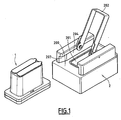
- the liquids to be filtered are collected in a preferably disposable filtration module generally marked with 1 to figure 1 and intended to be mounted on a support block generally marked by 2, forming part of the filtration machine (which is not shown as a whole in the figure).
- the filtration module 1 is placed on the support block to perform the filtration. When the filtration is finished, the filtration module 1 is removed from the support block 2 and the filter that is contained in the filtration module is removed to perform analyzes as will be explained later.
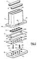
- the filtration module 1 shown exploded in the figure 2 , consists of a stack comprising, from top to bottom, a reservoir block 11, a striated seal 12, a filter 13, a plate seal 14 and a filter support drawer 15.
- the filter 13 is pressed against the lower face 110 of the reservoir block 11 via the filter support spool 15, the seal between the filter 13 and the reservoir block 11 being provided by the striated seal 12, and the seal between the filter 13 and the filter support spool 15 being provided by the plate gasket 14.
- the filter support drawer When the assembly is mounted, the filter support drawer is held in position against the reservoir block 11 by means of two assembly pins 16 which pass through holes 151 of the filter support drawer and catch on holes 112 provided in a lower rim 111 of the reservoir block 11, extending outwards.
- the reservoir block 11 made of plastic material, comprises a body 114 divided into two compartments 113 open at their upper part 115 and closed at their lower part. by a bottom 116 having a plurality of circular openings 117 of diameter between 0.6 cm and 2 cm.
- the bottom also comprises a rim 111 forming a collar in which are provided on the two lateral portions of the reservoir block openings 112 intended to receive the hooks of the assembly pins 16.
- the compartments 113 may be closed at their upper part by plugs Removable 17. Bottom and wall connection fillets of each compartment are rounded so as to create no particle retention zone to be filtered.
- the compartments 113 may have vertical grooves 118 for receiving separation blades 119 for dividing the compartments 113 into smaller compartments of a smaller volume.
- the grooves 118 are arranged such that any separation blades 119 are always arranged between two circular openings 117.
- the volume of the compartments is proportional to the number of circular openings 117, so that the total volume of the compartment or more exactly the maximum amount of liquid that can receive the compartment is between 0.14 ml / cm 2 and 40 ml / cm 2 multiplied by the sum of the surfaces of the openings in the bottom of the compartment.
- the height of the compartment and the bottom section is such that not only these conditions are respected for a complete compartment but also for them to be respected by any partial compartment delimited by means of one or more removable walls of 119 waterproof separation.
- each compartment can have a volume of 110 ml and have 5 openings in the bottom.
- the reservoir block 11 comprises a compartment 113, comprising five elementary filtration zones, a compartment 113 having an elementary filtration zone and two compartments 113 B having two elementary filtration zones.
- Each compartment includes a cap removable 17, 17A, 17B. Note that with this arrangement, it is possible to choose the number of elementary filter zones used between 1 and 10.
- the reservoir block On its lower face 110, the reservoir block comprises two different diameter holes (not shown in the figure) arranged diagonally, intended to cooperate with pins 153A and 153B of the filter support drawer 15, to ensure accurate positioning and locating the position of the filter relative to the bottom of the reservoir block.
- the grooved seal 12 disposed just below the reservoir block is a molded silicone seal having a plurality of holes 121 intended to come opposite the openings 117 provided in the bottom of the reservoir block, these holes 121 being surrounded by lips 122, and preferably two circular lips to ensure a good seal.
- the seal may further comprise longitudinal ribs 123 for separating a first series of holes and a second series of holes, so as to ensure the separation between the holes which are opposite a first compartment and the holes which are next to the second compartment of the reservoir block.
- This seal has the function of ensuring a perfect seal between each of the holes so that the liquid that passes through a hole can not mix with liquid passing through another hole, which allows two liquids to be filtered simultaneously. different.
- the protruding lips 122, and optionally 123 are disposed on the face 124 of the seal intended to cooperate with the lower part of the reservoir block 11.
- the second face 125 of the seal, intended to cooperate with the filter 13, is flat.
- the filter 13 which is a badge of generally rectangular shape and which is flat, comprises a central filtration zone 131 consisting of a microporous polycarbonate membrane approximately 100 microns thick and having a porosity suitable for the process. This central part is fixed with a biological glue on a PVC frame 132 which can be used to grasp the badge and to carry inscriptions for reference.
- the frame 132 comprises means for positioning and identifying the orientation of the badge constituted by two holes 133A and 133B disposed diagonally on the badge and having different diameters and intended to cooperate with the pins 153A and 153B of the filter support.
- the badge comprises two central filtration zones 131 A, 131 B, parallel to each other and which may comprise membranes of different porosities.
- the plate gasket 14 is a flat silicone gasket with circular openings 140 corresponding to the openings 121 of the striated gasket and the openings 117 provided in the bottom of the tank block. It also comprises holes 141 A and 141 B of different diameters corresponding to the holes 133A and 133B of the filter.
- the filter support spool 15 is an injected plastic plate having an upper face 150 for clamping the filter and seal assembly against the underside 110 of the reservoir block 11.
- This filter support plate has a series of holes 152. intended to come opposite the corresponding holes 140 of the plate gasket, 121 of the grooved joint and 117 of the reservoir block.
- the upper face 150 of the filter support slide further comprises pins 153A and 153B intended to cooperate with the locating holes 133A and 133B of the filter badge 13, with the corresponding holes 141A and 141B of the plate gasket 14 and with the centering holes. provided on the underside 110 of the reservoir block.
- the holes 152 for passing the filtered liquid comprise a funnel-shaped upper portion which is extended by small tubes 154 projecting on the lower face 155 of the filter support drawer 15.
- the small tubes 154 protruding from on the underside 155 of the filter support drawer function is to ensure a good flow of the liquid after filtration so as not to form drops that would wet the underside of the filter support.
- the diameter of the upper part of the holes 152, as well as the diameter of the holes 140 of the plate seal and 151 of the striated seal are substantially equal to the diameter of the holes 117 provided in the bottom of the reservoir block, in order to delimit on the filter of the elementary filtration zones of corresponding diameter.
- the filter support slide plate 15 further comprises on its two lateral edges holes 151 intended to receive the axes 16. These holes have shapes adapted to introduce the assembly pins and lock the assembly in position when it assures the assembly of the entire filtration module.
- the assembly axes 16 each comprise a head 161 surmounted by a rod 162, of smaller diameter, whose end constitutes a hook 163.
- the length of the assembly axis is adapted to allow the locking of the stack consisting of the filter support drawer, seals and filter when pressed against the tank block.
- an assembly axis is of sufficient length that, when it is inserted into a hole 151 of the filter support drawer, it can enter the hole 112 of the lower rim of the reservoir block 11, so that the hook 163 located at the end of the assembly axis can be hooked on the upper surface of the rim 111 of the reservoir block, the head 161 of the assembly pin 16 cooperating with the underside of the support drawer filter 15 so as to keep the filter support drawer locked against the bottom of the reservoir block 11.
- the filtration module as just described is intended to be disposed on a support block 2 of filtration module which comprises on the one hand a bearing surface 200 having a central opening 201 intended to come opposite all the openings of the lower face of a filtration unit, on the other hand a lever 202 pivoting about an axis 203 for manipulating two eccentrics 204 (only one visible in the figure) intended to ensure a good clamping the lower part of the filtration module against the surface 200 of the support block, and thereby ensure a good tightening of the reservoir block 11 against the filter support drawer 15 during the filtration operations.
- the lower rim 111 of the reservoir block and, optionally the filter support spool 15, comprise at one end, an enlarged portion 114 intended to cooperate with an enlarged portion 203 of the slide 204 of the support block 2 intended to receive the base of the module filtration.
- This arrangement makes it possible to impose an orientation of the filtration module with respect to the support block.
- the eccentrics are opposite the rim 111 of the reservoir block 11, so that when the lever is in an open position, the eccentrics leave room for flange 111 for sliding on the upper face 200 of the support block, and when the lever is in the position of tightening, the eccentrics strongly support the rim 111 of the reservoir block 11, so as to tighten the assembly constituted by the filter block, the filter, the filter support, and the associated joints, against the face 200 of the support of filtration module.
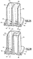
- each eccentric comprises a paddle 205 projecting outwardly, which, at the time of clamping the rim of the filtration module cooperates with the end of the corresponding connecting pin 16, so as to break the hook so that when complete tightening is assured, the hook of the assembly pin is broken. Due to this last arrangement, when the filtration module is clamped against the support block 2 via the eccentric, the assembly is held by the clamping, while, after loosening the eccentric, the head of the hook being broken, the filter support block and the reservoir block are no longer secured as shown in FIG. figure 7 . This makes it possible to take the filter, and at the same time makes the filtration module unusable for another analysis. Thus, the filtration module is for single use.
- the filtration module Before use, the filtration module is closed by the upper caps and sterilized.
- a sterilized filtration module is provided on a support block of a filtration machine. With the help of the clamping lever, the filtration module is locked on the filtering machine by ensuring that the filter support plate is securely clamped against the bottom of the reservoir block. In doing so and when the module is disposable, the ends with hooks of the assembly pins are broken. At least one of the compartments is then opened in which the liquid to be filtered is introduced in such a way that, in each compartment, the ratio of the quantity of liquid contained in the sum of the surfaces of the openings of the bottom of the compartment is between 0, 14 and 40 ml / cm 2 . The filtration is then carried out. Once filtration is complete, the system is unlocked by raising the clamping lever, and the filter module is removed.
- the lower part constituted by the filter support plate is separated from the reservoir block. The whole is then separated then the filter is taken that is available on the stage of a microscope observation, possibly after made a number of preparations using reagents so as to be able to properly observe the cells that may have been retained by the filter.
- This disposable device has the advantage of ensuring a good security of analysis. Indeed, the same device is used only for the analysis of a single sample, which avoids any risk of pollution of a sample by previous samples that would have been analyzed using the same device.
- the quantities of liquid filtered by the device are adapted so that the quantities filtered on each of the elementary filtration zones of the filter meet the conditions imposed by the process to obtain reliable results.
Landscapes
- Chemical & Material Sciences (AREA)
- Health & Medical Sciences (AREA)
- Clinical Laboratory Science (AREA)
- Chemical Kinetics & Catalysis (AREA)
- Analytical Chemistry (AREA)
- General Health & Medical Sciences (AREA)
- Hematology (AREA)
- Biochemistry (AREA)
- Life Sciences & Earth Sciences (AREA)
- General Physics & Mathematics (AREA)
- Immunology (AREA)
- Pathology (AREA)
- Physics & Mathematics (AREA)
- Investigating Or Analysing Biological Materials (AREA)
- Apparatus Associated With Microorganisms And Enzymes (AREA)
- Sampling And Sample Adjustment (AREA)
- Medicines Containing Material From Animals Or Micro-Organisms (AREA)
- Measuring Or Testing Involving Enzymes Or Micro-Organisms (AREA)
- Micro-Organisms Or Cultivation Processes Thereof (AREA)
Claims (23)
- Verfahren zum Untersuchen seltener Zellen in Suspension in einer Probe einer biologischen Flüssigkeit, um eine Diagnose zu ermöglichen, wobei das Verfahren die Schritte umfasst:a) Behandlung einer Probe einer biologischen Flüssigkeit zum Lysieren von Zellen, die nicht von Interesse sind;b) Vertikalfiltration der in Schritt a) erhaltenen, behandelten Probe durch einen Filter, welcher kalibrierte Poren mit einer Größe zwischen 3 µm und 100 µm und eine Porendichte zwischen 3 x 10³ und 5 x 10⁶ Poren/ cm2 umfasst, wobei der Filter mindestens einen elementaren Filtrationsbereich umfasst, wobei jeder elementare Filtrationsbereich eine Fläche aufweist, die gleich der einer Scheibe mit einem Durchmesser zwischen 0,6 cm und 3 cm ist und wobei die Anzahl von elementaren Filtrationsbereichen so ausgewählt ist, dass das Verhältnis des Volumens der zu filtrierenden Flüssigkeit zu der Summe der Flächen der elementaren Filtrationsbereiche zwischen 0,14 und 40 ml/ cm2 beträgt; undc) Analyse der Zellen, die in jedem elementaren Filtrationsbereich des Filters, welcher für das Filtrieren der Probe verwendet wurde, gewonnen werden konnten.
- Verfahren gemäß Anspruch 1, wobei jeder elementare Filtrationsbereich eine Fläche aufweist, die gleich der einer Scheibe mit einem Durchmesser von größer als oder gleich 0,8 cm ist.
- Verfahren gemäß einem der Ansprüche 1 oder 2, wobei der Filtrationsschritt mit einen Unterdruck zwischen 0,05 bar und 1 bar, gegebenenfalls mit einem Überdruck von weniger als 1 bar, durchgeführt wird.
- Verfahren gemäß einem der Ansprüche 1 bis 3, wobei die biologische Flüssigkeit Blut ist und wobei die kalibrierten Poren des Filters eine Größe zwischen 5 µm und 25 µm aufweisen.
- Verfahren gemäß einem der Ansprüche 1 bis 3, wobei die biologische Flüssigkeit Urin ist und wobei die kalibrierten Poren des Filters eine Größe zwischen 8 µm und 100 µm aufweisen.
- Verfahren gemäß Anspruch 1, wobei die auf dem Filter zurückgehaltenen Zellen während des Analyseschritts auf einen Objektträger übertragen werden.
- Verfahren gemäß Anspruch 4, wobei die biologische Flüssigkeit Blut ist und wobei die Behandlung in Schritt a) darin besteht, die roten Blutkörperchen des Bluts zu lysieren und die Blutgerinnung zu hemmen.
- Verfahren gemäß Anspruch 4, wobei der Schritt a) zusätzlich die Zugabe von Saponin und von EDTA zur biologischen Flüssigkeit umfasst, um die roten Blutkörperchen des Bluts zu lysieren und die Blutgerinnung zu hemmen.
- Verfahren gemäß Anspruch 1, wobei der Schritt a) zusätzlich die Fixierung kernhaltiger Zellen enthält.
- Verfahren gemäß Anspruch 9, wobei die Fixierung kernhaltiger Zellen durch die Zugabe von Formaldehyd zu der biologischen Flüssigkeit erfolgt.
- Verfahren gemäß Anspruch 1, wobei das Verfahren zusätzlich einen Schritt zur Bestimmung des Volumens der Probe der zu filtrierenden biologischen Flüssigkeit und einen Schritt der Teilung einer Kammer eines Filtrationsmoduls in Teilkammern mit einem kleineren Volumen umfasst, so dass das Verhältnis des Volumens der biologischen Flüssigkeit in jeder Teilkammer zu der Summe der Flächen der elementaren Filtrationsbereiche, welche mit der genannten Teilkammer verbunden sind, zwischen 0,14 ml/ cm2 und 40 ml/ cm2 beträgt.
- Verfahren gemäß Anspruch 1, wobei Schritt c), die Analyse der Zellen, welche bei Schritt b) auf den elementaren Filtrationsbereichen zurückgehalten werden, per Zellfärbung, Immunfärbung, FISH, PRINS, in situ PCR, Spektralphotometrie oder Laser-Mikrodissektion, gefolgt von molekularen Analysen, die auf ADN, ARN oder Proteine ausgerichtet sind, durchgeführt wird.
- Verfahren gemäß Anspruch 1, dadurch gekennzeichnet, dass bei Schritt c) die zurückgehaltenen Zellen durch Spülen mit einem geeigneten Puffer von dem Filter abgelöst werden und dann Analysen von ADN, ARN oder von Proteinen unterzogen werden.
- Verfahren gemäß Anspruch 1, wobei jeder elementare Filtrationsbereich eine Fläche aufweist, die gleich der einer Scheibe mit einem Durchmesser zwischen 0,8 cm und 1,5 cm ist.
- Filtrationsmodul (1) zur Durchführung des Verfahrens wie in einem der Ansprüche 1 bis 14 definiert, wobei der Typ umfasst:- eine Behältereinheit (11), welche mindestens eine Kammer (113) umfasst, deren unterer Teil durch einen Boden (116) mit mindestens einer Öffnung (117) geschlossen ist;- einen Filterträger-Einschub (15), welcher mindestens ein Loch (152) umfasst, wobei jedes Loch gegenüber einer Öffnung (117) der Behältereinheit angeordnet ist;- einen Filter (13), welcher zwischen der Unterseite (110) der Behältereinheit und dem Träger-Einschub eingelegt wird,dadurch gekennzeichnet, dass der Filter kalibrierte Poren mit einer Größe zwischen 3 µm und 100 µm und eine Porendichte zwischen 3 x 10³ und 5 x 10⁶ Poren/ cm2 umfasst, dass die Abmessungen jeder Öffnung (117) des Bodens der Behältereinheit und die Abmessungen jedes Lochs (152) des Filterträger-Einschubs so angepasst sind, dass jedes Paar, das aus einer Öffnung (117) des Bodens der Behältereinheit und dem zugehörigen Loch des Filterträger-Einschubs gebildet wird, einen elementaren Filtrationsbereich von begrenzter Fläche definiert, dadurch dass das Nutzvolumen jeder Kammer proportional ist zu der Anzahl von elementaren Filtrationsbereichen, die sich auf dem Boden der Kammer befinden, dass die Fläche eines elementaren Filtrationsbereichs gleich derer einer Scheibe mit einem Durchmesser zwischen 0,6 cm und 3 cm ist und dadurch, dass das das Verhältnis des Nutzvolumens jeder Kammer (113) zu der Summe der Flächen der elementaren Filtrationsbereiche zwischen 0,14 ml/ cm2 und 40 ml/ cm2 beträgt,
und dadurch, dass mindestens eine Kammer durch mindestens eine herausnehmbare Trennwand derart in Teilkammern unterteilt werden kann, dass mindestens eine Teilkammer in ihrem Boden mindestens eine Öffnung enthält, wobei das Verhältnis des Volumens der Teilkammer zu der Summe der Flächen der Öffnungen, die im Boden der Teilkammer enthalten sind, zwischen 0,14 ml/ cm2 und 40 ml/ cm2 beträgt. - Filtrationsmodul gemäß Anspruch 15, wobei die Abmessungen der mindestens einen Öffnung (117) des Bodens der Behältereinheit und eines entsprechenden Lochs (152) des Filterträger-Einschubs so angepasst sind, dass die Fläche des entsprechenden elementaren Filtrationsbereichs größer oder gleich derer einer Scheibe mit einem Durchmesser von 0,8 cm ist.
- Filtrationsmodul gemäß einem der Ansprüche 15 bis 16, umfassend eine geriffelte Dichtung, welche zwischen dem Boden der Behältereinheit (11) und dem Filter (13) angeordnet ist und welche mindestens ein Loch (121) enthält, das mit einer Öffnung (117) des Bodens der Behältereinheit übereinstimmt, wobei das Loch von mindestens einer hervorstehenden Lippe (122) umgeben ist.
- Filtrationsmodul gemäß einem der Ansprüche 15 bis 17, weiterhin umfassend eine Plattendichtung (14) zwischen dem Filter (13) und dem Filterträger (15), welche mindestens eine Öffnung (140) gegenüber einem Loch (152) des Filterträgers (15) enthält.
- Filtrationsmodul gemäß einem der Ansprüche 15 bis 18, wobei der Filter (13) eine Plakette (un badge) bildet, deren zentraler Teil mindestens einen porösen Bereich (131, 131 A, 131 B) enthält und deren Peripherie einen Rahmen bildet, welcher Mittel zur Indexierung ihrer Position auf dem Filterträger enthält.
- Filtrationsmodul gemäß Anspruch 19, wobei die Indexierungsmittel mindestens zwei Löcher (133A, 133B) mit unterschiedlichem Durchmesser darstellen, welche dazu bestimmt sind, mit Stiften (153A, 153B) entsprechenden Durchmessers, die auf dem Filterträger vorgesehen sind, zusammenzuwirken.
- Filtrationsmodul gemäß einem der Ansprüche 15 bis 20, weiterhin umfassend mindestens einen Deckel (17) zum Verschließen der oberen Öffnung einer Kammer (113).
- Filtrationsmodul gemäß einem der Ansprüche 15 bis 21, dadurch gekennzeichnet, dass die Behältereinheit (11) in ihrem unteren Teil einen Rand enthält, welcher sich nach außen hin erstreckt und mit mindestens einem Verbindungsstift (16) zusammenwirkt, wodurch ermöglicht wird den Filter (13) zwischen dem Filterträger (15) und der Behältereinheit (11) einzuspannen, wobei der Verbindungsstift (16) ein teilbares Endstück (163) enthält, welches sich oben zu dem Rand der Behältereinheit hin erstreckt.
- Filtrationsmodul gemäß einem der Ansprüche 15 bis 21, wobei alle Teile aus Materialien bestehen, die für einen Sterilisationsbetrieb geeignet sind oder dafür bestimmt sind, diese von RNAse, DNAse oder Proteinase zu befreien.
Priority Applications (2)
| Application Number | Priority Date | Filing Date | Title |
|---|---|---|---|
| DK13159197.6T DK2633912T3 (en) | 2005-03-24 | 2006-03-14 | Device for separation by vertical filtration of biological particles contained in a liquid |
| EP13159197.6A EP2633912B1 (de) | 2005-03-24 | 2006-03-14 | Vorrichtung zum Trennen durch vertikale Filtrierung von biologischen Partikeln, die in einer Flüssigkeit enthalten sind |
Applications Claiming Priority (2)
| Application Number | Priority Date | Filing Date | Title |
|---|---|---|---|
| FR0502945A FR2883488B1 (fr) | 2005-03-24 | 2005-03-24 | Procede et dispositif pour separer par filtration verticale des particules biologiques contenues dans un liquide |
| PCT/FR2006/000562 WO2006100366A2 (fr) | 2005-03-24 | 2006-03-14 | Procede et dispositif pour separer par filtration verticale des particules biologiques contenues dans un liquide |
Related Child Applications (2)
| Application Number | Title | Priority Date | Filing Date |
|---|---|---|---|
| EP13159197.6A Division EP2633912B1 (de) | 2005-03-24 | 2006-03-14 | Vorrichtung zum Trennen durch vertikale Filtrierung von biologischen Partikeln, die in einer Flüssigkeit enthalten sind |
| EP13159197.6A Division-Into EP2633912B1 (de) | 2005-03-24 | 2006-03-14 | Vorrichtung zum Trennen durch vertikale Filtrierung von biologischen Partikeln, die in einer Flüssigkeit enthalten sind |
Publications (2)
| Publication Number | Publication Date |
|---|---|
| EP1866091A2 EP1866091A2 (de) | 2007-12-19 |
| EP1866091B1 true EP1866091B1 (de) | 2015-07-29 |
Family
ID=35229619
Family Applications (2)
| Application Number | Title | Priority Date | Filing Date |
|---|---|---|---|
| EP06726089.3A Active EP1866091B1 (de) | 2005-03-24 | 2006-03-14 | Verfahren und vorrichtung zur abtrennung von in einer flüssigkeit enthaltenen biologischen teilchen mittels vertikalfiltration |
| EP13159197.6A Active EP2633912B1 (de) | 2005-03-24 | 2006-03-14 | Vorrichtung zum Trennen durch vertikale Filtrierung von biologischen Partikeln, die in einer Flüssigkeit enthalten sind |
Family Applications After (1)
| Application Number | Title | Priority Date | Filing Date |
|---|---|---|---|
| EP13159197.6A Active EP2633912B1 (de) | 2005-03-24 | 2006-03-14 | Vorrichtung zum Trennen durch vertikale Filtrierung von biologischen Partikeln, die in einer Flüssigkeit enthalten sind |
Country Status (9)
| Country | Link |
|---|---|
| US (3) | US20090226957A1 (de) |
| EP (2) | EP1866091B1 (de) |
| JP (1) | JP5254000B2 (de) |
| CA (1) | CA2601451C (de) |
| DK (1) | DK2633912T3 (de) |
| ES (1) | ES2549856T3 (de) |
| FR (2) | FR2883488B1 (de) |
| HU (1) | HUE032161T2 (de) |
| WO (1) | WO2006100366A2 (de) |
Families Citing this family (29)
| Publication number | Priority date | Publication date | Assignee | Title |
|---|---|---|---|---|
| US8921102B2 (en) | 2005-07-29 | 2014-12-30 | Gpb Scientific, Llc | Devices and methods for enrichment and alteration of circulating tumor cells and other particles |
| US20080050739A1 (en) | 2006-06-14 | 2008-02-28 | Roland Stoughton | Diagnosis of fetal abnormalities using polymorphisms including short tandem repeats |
| US8137912B2 (en) | 2006-06-14 | 2012-03-20 | The General Hospital Corporation | Methods for the diagnosis of fetal abnormalities |
| WO2007147074A2 (en) | 2006-06-14 | 2007-12-21 | Living Microsystems, Inc. | Use of highly parallel snp genotyping for fetal diagnosis |
| US8372584B2 (en) | 2006-06-14 | 2013-02-12 | The General Hospital Corporation | Rare cell analysis using sample splitting and DNA tags |
| US20090302190A1 (en) | 2006-10-25 | 2009-12-10 | Fraunhofer-Gesellschaft Zur Foerderung Der Angewandten Forschung E.V. | Chip holder, fluidic system and chip holder system |
| FR2921490B1 (fr) * | 2007-09-21 | 2010-09-10 | Metagenex | Procede et dispositif pour recueillir du materiel cellulaire de cellules isolees sur filtre |
| CA3069081C (en) | 2008-09-20 | 2023-05-23 | The Board Of Trustees Of The Leland Stanford Junior University | Noninvasive diagnosis of fetal aneuploidy by sequencing |
| JP2012504956A (ja) | 2008-10-10 | 2012-03-01 | セントレ ナショナル デ ラ レシェルシェ サイエンティフィーク−ディーエーイー | 細胞ソート・デバイス |
| WO2010135603A2 (en) | 2009-05-20 | 2010-11-25 | California Institute Of Technology | Method for cancer detection, diagnosis and prognosis |
| FR2952069B1 (fr) | 2009-11-04 | 2013-06-28 | Metagenex | Dispositif et procede pour isoler et/ou cultiver des cellules vivantes sur filtre ou extraire leur materiel genetique |
| US9372134B2 (en) * | 2010-04-15 | 2016-06-21 | Cytogen Co., Ltd. | Microfluidic device and method for isolating target using same |
| DE102011076221B3 (de) * | 2011-05-20 | 2012-07-12 | Siemens Aktiengesellschaft | Automatisierter CTC Nachweis |
| EP3351935B1 (de) * | 2012-05-24 | 2020-08-12 | Assistance Publique-Hôpitaux de Paris | Verfahren zur multianalyse von aus biologischen proben mittels filtration extrahierten oder isolierten seltenen zellen |
| CN102871771B (zh) * | 2012-09-04 | 2015-02-18 | 清华大学 | 利用旋转组合模具制备纺锤状复杂器官前体的方法 |
| US10248765B1 (en) | 2012-12-05 | 2019-04-02 | Theranos Ip Company, Llc | Systems, devices, and methods for bodily fluid sample collection, transport, and handling |
| US9386948B2 (en) | 2012-12-05 | 2016-07-12 | Theranos, Inc. | Systems, devices, and methods for bodily fluid sample transport |
| US20140323911A1 (en) * | 2013-03-15 | 2014-10-30 | Theranos, Inc. | Methods and devices for sample collection and sample separation |
| MX365324B (es) | 2013-03-15 | 2019-05-29 | Theranos Ip Co Llc | Metodos y dispositivos para recoleccion de muestras y separacion de muestras. |
| CN103255055A (zh) * | 2013-04-24 | 2013-08-21 | 宁波美晶医疗技术有限公司 | 一种卡扣型生物芯片 |
| EP3031903A4 (de) | 2013-08-09 | 2017-04-26 | Hitachi Chemical Co., Ltd. | Zelleneinfangvorrichtung, zelleneinfangvorrichtung und herstellungsverfahren für eine zelleneinfangvorrichtung |
| FR3012978A1 (fr) | 2013-11-12 | 2015-05-15 | Biocarecell | Filtre biocompatible et procede de fabrication d'un filtre biocompatible. |
| EP3304082B1 (de) | 2015-06-08 | 2020-05-13 | Arquer Diagnostics Limited | Methode zur analyse einer urinprobe |
| EP4060344A1 (de) | 2015-06-08 | 2022-09-21 | Arquer Diagnostics Limited | Verfahren und kits |
| US10371606B2 (en) | 2015-07-21 | 2019-08-06 | Theraos IP Company, LLC | Bodily fluid sample collection and transport |
| US11247208B2 (en) | 2015-09-09 | 2022-02-15 | Labrador Diagnostics Llc | Methods and devices for sample collection and sample separation |
| EP3351921A4 (de) | 2015-09-14 | 2019-08-21 | National University Corporation Shiga University OF Medical Science | Zellhaltesubstrathalter zur vorbereitung einer beobachtungsprobe, kit damit und verfahren für die zubereitung einer beobachtungsprobe |
| US11857966B1 (en) | 2017-03-15 | 2024-01-02 | Labrador Diagnostics Llc | Methods and devices for sample collection and sample separation |
| JP2022548289A (ja) * | 2019-09-18 | 2022-11-17 | 日東電工株式会社 | 生体液を分配及び分析する装置 |
Citations (1)
| Publication number | Priority date | Publication date | Assignee | Title |
|---|---|---|---|---|
| FR2809142A1 (fr) * | 2000-05-18 | 2001-11-23 | Clauger | Dispositif de fixation a came de serrage amovible |
Family Cites Families (21)
| Publication number | Priority date | Publication date | Assignee | Title |
|---|---|---|---|---|
| US3888770A (en) * | 1971-10-21 | 1975-06-10 | Shlomo Avital | Plural-sample filter device |
| US4510119A (en) * | 1982-05-07 | 1985-04-09 | Centocor, Inc. | Diagnostic test bead transfer apparatus |
| US4493815A (en) * | 1983-07-28 | 1985-01-15 | Bio-Rad Laboratories, Inc. | Supporting and filtering biochemical test plate assembly |
| US4787988A (en) * | 1987-02-20 | 1988-11-29 | Biomedical Research And Development Laboratories, Inc. | Cell harvester |
| US4985631A (en) * | 1988-02-16 | 1991-01-15 | Wannlund Jon C | Luminescence exposure apparatus |
| FR2638101B1 (fr) * | 1988-10-21 | 1991-09-06 | Biocom Sa | Dispositif de filtration parallele d'une pluralite d'echantillons avec controle automatique des volumes filtres et du colmatage ainsi qu'avec indexation du filtre, et procede de filtration |
| JPH02176466A (ja) * | 1988-12-27 | 1990-07-09 | Mochida Pharmaceut Co Ltd | 液性試料中の特定物質の測定方法および測定器具 |
| FR2657543B1 (fr) * | 1990-01-26 | 1992-12-18 | Biocom Sa | Dispositif modulaire pour le recueil, l'incubation, la filtration d'echantillons multiples. |
| US5205989A (en) * | 1991-09-18 | 1993-04-27 | Minnesota Mining And Manufacturing Company | Multi-well filtration apparatus |
| CA2131090A1 (en) * | 1992-03-20 | 1993-09-21 | Peter Leonard Grant | Method and apparatus for the analysis of biological material |
| EP1065001B1 (de) * | 1998-03-19 | 2008-09-24 | Precision System Science Co., Ltd. | Apparat zur integration von magnetteilchen - verarbeitung und steuerungsverfahren |
| FR2782730B1 (fr) * | 1998-08-25 | 2002-05-17 | Biocom Sa | Procede de separation cellulaire pour l'isolation de cellules pathogeniques, notamment cancereuses rares, equipement et reactif pour la mise en oeuvre du procede et application du procede |
| JP2000180443A (ja) * | 1998-12-15 | 2000-06-30 | Fuji Photo Film Co Ltd | 血液濾過残留物の回収方法 |
| US6852290B2 (en) * | 2001-03-08 | 2005-02-08 | Exelixis, Inc. | Multi-well apparatus |
| FR2824144B1 (fr) * | 2001-04-30 | 2004-09-17 | Metagenex S A R L | Methode de diagnostic prenatal sur cellule foetale isolee du sang maternel |
| US7166443B2 (en) * | 2001-10-11 | 2007-01-23 | Aviva Biosciences Corporation | Methods, compositions, and automated systems for separating rare cells from fluid samples |
| US20030175157A1 (en) * | 2002-01-25 | 2003-09-18 | Irm, Llc | Fluid handling methods and systems |
| AT500523B1 (de) * | 2002-04-30 | 2007-09-15 | Greiner Bio One Gmbh | Vorrichtung zur proteinkristallisation |
| WO2004060534A1 (en) * | 2002-12-18 | 2004-07-22 | Millipore Corporation | Combination laboratory device with multifunctionality |
| US7507376B2 (en) * | 2002-12-19 | 2009-03-24 | 3M Innovative Properties Company | Integrated sample processing devices |
| WO2005021130A1 (en) * | 2003-09-03 | 2005-03-10 | Cedi Diagnostics B.V. | Method of detecting multiple analytes |
-
2005
- 2005-03-24 FR FR0502945A patent/FR2883488B1/fr not_active Expired - Fee Related
-
2006
- 2006-03-14 US US11/908,545 patent/US20090226957A1/en not_active Abandoned
- 2006-03-14 EP EP06726089.3A patent/EP1866091B1/de active Active
- 2006-03-14 WO PCT/FR2006/000562 patent/WO2006100366A2/fr active Application Filing
- 2006-03-14 DK DK13159197.6T patent/DK2633912T3/en active
- 2006-03-14 CA CA2601451A patent/CA2601451C/fr active Active
- 2006-03-14 JP JP2008502434A patent/JP5254000B2/ja active Active
- 2006-03-14 EP EP13159197.6A patent/EP2633912B1/de active Active
- 2006-03-14 ES ES06726089.3T patent/ES2549856T3/es active Active
- 2006-03-14 HU HUE13159197A patent/HUE032161T2/en unknown
-
2010
- 2010-10-15 FR FR1058439A patent/FR2947738B1/fr not_active Expired - Fee Related
-
2014
- 2014-10-17 US US14/517,288 patent/US9766167B2/en active Active
-
2017
- 2017-09-18 US US15/707,993 patent/US10436686B2/en active Active
Patent Citations (1)
| Publication number | Priority date | Publication date | Assignee | Title |
|---|---|---|---|---|
| FR2809142A1 (fr) * | 2000-05-18 | 2001-11-23 | Clauger | Dispositif de fixation a came de serrage amovible |
Also Published As
| Publication number | Publication date |
|---|---|
| JP2008537485A (ja) | 2008-09-18 |
| FR2883488A1 (fr) | 2006-09-29 |
| FR2883488B1 (fr) | 2010-12-10 |
| WO2006100366A3 (fr) | 2007-09-20 |
| US9766167B2 (en) | 2017-09-19 |
| FR2947738A1 (fr) | 2011-01-14 |
| ES2549856T3 (es) | 2015-11-02 |
| EP1866091A2 (de) | 2007-12-19 |
| HUE032161T2 (en) | 2017-09-28 |
| CA2601451C (fr) | 2013-07-16 |
| JP5254000B2 (ja) | 2013-07-31 |
| FR2947738B1 (fr) | 2014-06-13 |
| US20180003602A1 (en) | 2018-01-04 |
| EP2633912B1 (de) | 2016-12-28 |
| EP2633912A1 (de) | 2013-09-04 |
| US20150104791A1 (en) | 2015-04-16 |
| WO2006100366A2 (fr) | 2006-09-28 |
| US10436686B2 (en) | 2019-10-08 |
| CA2601451A1 (fr) | 2006-09-28 |
| DK2633912T3 (en) | 2017-03-13 |
| US20090226957A1 (en) | 2009-09-10 |
Similar Documents
| Publication | Publication Date | Title |
|---|---|---|
| EP1866091B1 (de) | Verfahren und vorrichtung zur abtrennung von in einer flüssigkeit enthaltenen biologischen teilchen mittels vertikalfiltration | |
| EP2238236B1 (de) | Vorrichtung und verfahren zur isolierung und kultivierung lebender zellen auf einem filter oder derer extraktion von genetischem material | |
| CA2732553C (fr) | Dispositif pour la capture de particules biologiques et utilisation | |
| EP0513139B1 (de) | Modulare vorrichtung zum sammeln, inkubieren und filtrieren von mehreren proben | |
| DK2954758T3 (en) | plasma Source | |
| EP2550536A1 (de) | Automatisches verfahren und automatisierte vorrichtung für die vorbereitung und analyse mehrerer zellsuspensionen | |
| FR2952069A1 (fr) | Dispositif et procede pour isoler et/ou cultiver des cellules vivantes sur filtre ou extraire leur materiel genetique | |
| FR2748569A1 (fr) | Procede et installation de separation de particules magnetiques dans un fluide pour l'analyse biologique, et application dudit procede | |
| JP6027010B2 (ja) | 固定のためのフィルタアセンブリ | |
| WO2009047436A1 (fr) | Procédé, dispositif et kit de biologie moléculaire permettant l'extraction du matériel génétique amplifié | |
| EP3177922B1 (de) | Verfahren zur erkennung der sichelzellkrankheit | |
| WO2021152097A1 (fr) | Dispositif pour analyser des elements solides biologiques et dispositif pour sa mise en oeuvre | |
| US20120085712A1 (en) | Filter apparatus and method |
Legal Events
| Date | Code | Title | Description |
|---|---|---|---|
| PUAI | Public reference made under article 153(3) epc to a published international application that has entered the european phase |
Free format text: ORIGINAL CODE: 0009012 |
|
| 17P | Request for examination filed |
Effective date: 20070914 |
|
| AK | Designated contracting states |
Kind code of ref document: A2 Designated state(s): AT BE BG CH CY CZ DE DK EE ES FI FR GB GR HU IE IS IT LI LT LU LV MC NL PL PT RO SE SI SK TR |
|
| AX | Request for extension of the european patent |
Extension state: AL BA HR MK YU |
|
| DAX | Request for extension of the european patent (deleted) | ||
| 17Q | First examination report despatched |
Effective date: 20110314 |
|
| GRAP | Despatch of communication of intention to grant a patent |
Free format text: ORIGINAL CODE: EPIDOSNIGR1 |
|
| INTG | Intention to grant announced |
Effective date: 20150220 |
|
| GRAS | Grant fee paid |
Free format text: ORIGINAL CODE: EPIDOSNIGR3 |
|
| GRAA | (expected) grant |
Free format text: ORIGINAL CODE: 0009210 |
|
| AK | Designated contracting states |
Kind code of ref document: B1 Designated state(s): AT BE BG CH CY CZ DE DK EE ES FI FR GB GR HU IE IS IT LI LT LU LV MC NL PL PT RO SE SI SK TR |
|
| REG | Reference to a national code |
Ref country code: GB Ref legal event code: FG4D Free format text: NOT ENGLISH |
|
| REG | Reference to a national code |
Ref country code: CH Ref legal event code: EP |
|
| REG | Reference to a national code |
Ref country code: AT Ref legal event code: REF Ref document number: 738837 Country of ref document: AT Kind code of ref document: T Effective date: 20150815 |
|
| REG | Reference to a national code |
Ref country code: IE Ref legal event code: FG4D Free format text: LANGUAGE OF EP DOCUMENT: FRENCH |
|
| REG | Reference to a national code |
Ref country code: DE Ref legal event code: R096 Ref document number: 602006046103 Country of ref document: DE |
|
| REG | Reference to a national code |
Ref country code: CH Ref legal event code: NV Representative=s name: ARNOLD AND SIEDSMA AG, CH |
|
| REG | Reference to a national code |
Ref country code: DE Ref legal event code: R082 Ref document number: 602006046103 Country of ref document: DE Representative=s name: LAVOIX MUNICH, DE |
|
| REG | Reference to a national code |
Ref country code: NL Ref legal event code: FP |
|
| REG | Reference to a national code |
Ref country code: AT Ref legal event code: MK05 Ref document number: 738837 Country of ref document: AT Kind code of ref document: T Effective date: 20150729 |
|
| REG | Reference to a national code |
Ref country code: LT Ref legal event code: MG4D |
|
| PG25 | Lapsed in a contracting state [announced via postgrant information from national office to epo] |
Ref country code: LV Free format text: LAPSE BECAUSE OF FAILURE TO SUBMIT A TRANSLATION OF THE DESCRIPTION OR TO PAY THE FEE WITHIN THE PRESCRIBED TIME-LIMIT Effective date: 20150729 Ref country code: GR Free format text: LAPSE BECAUSE OF FAILURE TO SUBMIT A TRANSLATION OF THE DESCRIPTION OR TO PAY THE FEE WITHIN THE PRESCRIBED TIME-LIMIT Effective date: 20151030 Ref country code: FI Free format text: LAPSE BECAUSE OF FAILURE TO SUBMIT A TRANSLATION OF THE DESCRIPTION OR TO PAY THE FEE WITHIN THE PRESCRIBED TIME-LIMIT Effective date: 20150729 Ref country code: LT Free format text: LAPSE BECAUSE OF FAILURE TO SUBMIT A TRANSLATION OF THE DESCRIPTION OR TO PAY THE FEE WITHIN THE PRESCRIBED TIME-LIMIT Effective date: 20150729 |
|
| PG25 | Lapsed in a contracting state [announced via postgrant information from national office to epo] |
Ref country code: AT Free format text: LAPSE BECAUSE OF FAILURE TO SUBMIT A TRANSLATION OF THE DESCRIPTION OR TO PAY THE FEE WITHIN THE PRESCRIBED TIME-LIMIT Effective date: 20150729 Ref country code: IS Free format text: LAPSE BECAUSE OF FAILURE TO SUBMIT A TRANSLATION OF THE DESCRIPTION OR TO PAY THE FEE WITHIN THE PRESCRIBED TIME-LIMIT Effective date: 20151129 Ref country code: PT Free format text: LAPSE BECAUSE OF FAILURE TO SUBMIT A TRANSLATION OF THE DESCRIPTION OR TO PAY THE FEE WITHIN THE PRESCRIBED TIME-LIMIT Effective date: 20151130 Ref country code: PL Free format text: LAPSE BECAUSE OF FAILURE TO SUBMIT A TRANSLATION OF THE DESCRIPTION OR TO PAY THE FEE WITHIN THE PRESCRIBED TIME-LIMIT Effective date: 20150729 Ref country code: SE Free format text: LAPSE BECAUSE OF FAILURE TO SUBMIT A TRANSLATION OF THE DESCRIPTION OR TO PAY THE FEE WITHIN THE PRESCRIBED TIME-LIMIT Effective date: 20150729 |
|
| REG | Reference to a national code |
Ref country code: FR Ref legal event code: PLFP Year of fee payment: 11 |
|
| PG25 | Lapsed in a contracting state [announced via postgrant information from national office to epo] |
Ref country code: DK Free format text: LAPSE BECAUSE OF FAILURE TO SUBMIT A TRANSLATION OF THE DESCRIPTION OR TO PAY THE FEE WITHIN THE PRESCRIBED TIME-LIMIT Effective date: 20150729 Ref country code: CZ Free format text: LAPSE BECAUSE OF FAILURE TO SUBMIT A TRANSLATION OF THE DESCRIPTION OR TO PAY THE FEE WITHIN THE PRESCRIBED TIME-LIMIT Effective date: 20150729 Ref country code: EE Free format text: LAPSE BECAUSE OF FAILURE TO SUBMIT A TRANSLATION OF THE DESCRIPTION OR TO PAY THE FEE WITHIN THE PRESCRIBED TIME-LIMIT Effective date: 20150729 Ref country code: SK Free format text: LAPSE BECAUSE OF FAILURE TO SUBMIT A TRANSLATION OF THE DESCRIPTION OR TO PAY THE FEE WITHIN THE PRESCRIBED TIME-LIMIT Effective date: 20150729 |
|
| REG | Reference to a national code |
Ref country code: DE Ref legal event code: R097 Ref document number: 602006046103 Country of ref document: DE |
|
| PG25 | Lapsed in a contracting state [announced via postgrant information from national office to epo] |
Ref country code: RO Free format text: LAPSE BECAUSE OF FAILURE TO SUBMIT A TRANSLATION OF THE DESCRIPTION OR TO PAY THE FEE WITHIN THE PRESCRIBED TIME-LIMIT Effective date: 20150729 |
|
| PLBE | No opposition filed within time limit |
Free format text: ORIGINAL CODE: 0009261 |
|
| STAA | Information on the status of an ep patent application or granted ep patent |
Free format text: STATUS: NO OPPOSITION FILED WITHIN TIME LIMIT |
|
| 26N | No opposition filed |
Effective date: 20160502 |
|
| PG25 | Lapsed in a contracting state [announced via postgrant information from national office to epo] |
Ref country code: SI Free format text: LAPSE BECAUSE OF FAILURE TO SUBMIT A TRANSLATION OF THE DESCRIPTION OR TO PAY THE FEE WITHIN THE PRESCRIBED TIME-LIMIT Effective date: 20150729 |
|
| REG | Reference to a national code |
Ref country code: FR Ref legal event code: PLFP Year of fee payment: 12 |
|
| REG | Reference to a national code |
Ref country code: FR Ref legal event code: PLFP Year of fee payment: 13 |
|
| PG25 | Lapsed in a contracting state [announced via postgrant information from national office to epo] |
Ref country code: CY Free format text: LAPSE BECAUSE OF FAILURE TO SUBMIT A TRANSLATION OF THE DESCRIPTION OR TO PAY THE FEE WITHIN THE PRESCRIBED TIME-LIMIT Effective date: 20150729 Ref country code: HU Free format text: LAPSE BECAUSE OF FAILURE TO SUBMIT A TRANSLATION OF THE DESCRIPTION OR TO PAY THE FEE WITHIN THE PRESCRIBED TIME-LIMIT; INVALID AB INITIO Effective date: 20060314 |
|
| PG25 | Lapsed in a contracting state [announced via postgrant information from national office to epo] |
Ref country code: TR Free format text: LAPSE BECAUSE OF FAILURE TO SUBMIT A TRANSLATION OF THE DESCRIPTION OR TO PAY THE FEE WITHIN THE PRESCRIBED TIME-LIMIT Effective date: 20150729 |
|
| PG25 | Lapsed in a contracting state [announced via postgrant information from national office to epo] |
Ref country code: BG Free format text: LAPSE BECAUSE OF FAILURE TO SUBMIT A TRANSLATION OF THE DESCRIPTION OR TO PAY THE FEE WITHIN THE PRESCRIBED TIME-LIMIT Effective date: 20150729 |
|
| PGFP | Annual fee paid to national office [announced via postgrant information from national office to epo] |
Ref country code: NL Payment date: 20190218 Year of fee payment: 18 |
|
| PG25 | Lapsed in a contracting state [announced via postgrant information from national office to epo] |
Ref country code: MC Free format text: LAPSE BECAUSE OF NON-PAYMENT OF DUE FEES Effective date: 20200331 |
|
| REG | Reference to a national code |
Ref country code: NL Ref legal event code: MM Effective date: 20200401 |
|
| PG25 | Lapsed in a contracting state [announced via postgrant information from national office to epo] |
Ref country code: NL Free format text: LAPSE BECAUSE OF NON-PAYMENT OF DUE FEES Effective date: 20200401 |
|
| REG | Reference to a national code |
Ref country code: LU Ref legal event code: PD Owner name: UNIVERSITE DE PARIS; FR Free format text: FORMER OWNER: UNIVERSITE RENE DESCARTES (PARIS V) Effective date: 20210813 |
|
| REG | Reference to a national code |
Ref country code: CH Ref legal event code: PK Free format text: RECTIFICATIONS |
|
| REG | Reference to a national code |
Ref country code: BE Ref legal event code: PD Owner name: UNIVERSITE DE PARIS; FR Free format text: DETAILS ASSIGNMENT: CHANGE OF OWNER(S), MERGE; FORMER OWNER NAME: UNIVERSITE RENE DESCARTES (PARIS V) Effective date: 20211013 |
|
| REG | Reference to a national code |
Ref country code: GB Ref legal event code: 732E Free format text: REGISTERED BETWEEN 20220113 AND 20220119 |
|
| REG | Reference to a national code |
Ref country code: DE Ref legal event code: R081 Ref document number: 602006046103 Country of ref document: DE Owner name: UNIVERSITE PARIS CITE, FR Free format text: FORMER OWNERS: ASSISTANCE PUBLIQUE-HOPITAUX DE PARIS, PARIS, FR; INSTITUT NATIONAL DE LA SANTE ET DE LA RECHERCHE MEDICALE (INSERM), PARIS, FR; UNIVERSITE RENE DESCARTES-PARIS V, PARIS, FR Ref country code: DE Ref legal event code: R081 Ref document number: 602006046103 Country of ref document: DE Owner name: UNIVERSITE DE PARIS, FR Free format text: FORMER OWNERS: ASSISTANCE PUBLIQUE-HOPITAUX DE PARIS, PARIS, FR; INSTITUT NATIONAL DE LA SANTE ET DE LA RECHERCHE MEDICALE (INSERM), PARIS, FR; UNIVERSITE RENE DESCARTES-PARIS V, PARIS, FR Ref country code: DE Ref legal event code: R081 Ref document number: 602006046103 Country of ref document: DE Owner name: INSTITUT NATIONAL DE LA SANTE ET DE LA RECHERC, FR Free format text: FORMER OWNERS: ASSISTANCE PUBLIQUE-HOPITAUX DE PARIS, PARIS, FR; INSTITUT NATIONAL DE LA SANTE ET DE LA RECHERCHE MEDICALE (INSERM), PARIS, FR; UNIVERSITE RENE DESCARTES-PARIS V, PARIS, FR Ref country code: DE Ref legal event code: R081 Ref document number: 602006046103 Country of ref document: DE Owner name: ASSISTANCE PUBLIQUE-HOPITAUX DE PARIS, FR Free format text: FORMER OWNERS: ASSISTANCE PUBLIQUE-HOPITAUX DE PARIS, PARIS, FR; INSTITUT NATIONAL DE LA SANTE ET DE LA RECHERCHE MEDICALE (INSERM), PARIS, FR; UNIVERSITE RENE DESCARTES-PARIS V, PARIS, FR |
|
| REG | Reference to a national code |
Ref country code: DE Ref legal event code: R081 Ref document number: 602006046103 Country of ref document: DE Owner name: UNIVERSITE PARIS CITE, FR Free format text: FORMER OWNERS: ASSISTANCE PUBLIQUE-HOPITAUX DE PARIS, PARIS, FR; INSTITUT NATIONAL DE LA SANTE ET DE LA RECHERCHE MEDICALE (INSERM), PARIS, FR; UNIVERSITE DE PARIS, PARIS, FR Ref country code: DE Ref legal event code: R081 Ref document number: 602006046103 Country of ref document: DE Owner name: INSTITUT NATIONAL DE LA SANTE ET DE LA RECHERC, FR Free format text: FORMER OWNERS: ASSISTANCE PUBLIQUE-HOPITAUX DE PARIS, PARIS, FR; INSTITUT NATIONAL DE LA SANTE ET DE LA RECHERCHE MEDICALE (INSERM), PARIS, FR; UNIVERSITE DE PARIS, PARIS, FR Ref country code: DE Ref legal event code: R081 Ref document number: 602006046103 Country of ref document: DE Owner name: ASSISTANCE PUBLIQUE-HOPITAUX DE PARIS, FR Free format text: FORMER OWNERS: ASSISTANCE PUBLIQUE-HOPITAUX DE PARIS, PARIS, FR; INSTITUT NATIONAL DE LA SANTE ET DE LA RECHERCHE MEDICALE (INSERM), PARIS, FR; UNIVERSITE DE PARIS, PARIS, FR |
|
| REG | Reference to a national code |
Ref country code: LU Ref legal event code: HC Owner name: ASSISTANCE PUBLIQUE - HOPITAUX DE PARIS; FR Free format text: FORMER OWNER: UNIVERSITE DE PARIS Effective date: 20220720 |
|
| REG | Reference to a national code |
Ref country code: BE Ref legal event code: HC Owner name: ASSISTANCE PUBLIQUE - HOPITAUX DE PARIS; FR Free format text: DETAILS ASSIGNMENT: CHANGE OF OWNER(S), CHANGE OF OWNER(S) NAME; FORMER OWNER NAME: UNIVERSITE DE PARIS Effective date: 20220812 |
|
| REG | Reference to a national code |
Ref country code: ES Ref legal event code: PC2A Owner name: UNIVERSITE DE PARIS Effective date: 20221216 |
|
| REG | Reference to a national code |
Ref country code: ES Ref legal event code: PC2A Owner name: UNIVERSITE PARIS CITE Effective date: 20230201 |
|
| PGFP | Annual fee paid to national office [announced via postgrant information from national office to epo] |
Ref country code: LU Payment date: 20230227 Year of fee payment: 18 Ref country code: IE Payment date: 20230220 Year of fee payment: 18 Ref country code: FR Payment date: 20230209 Year of fee payment: 18 |
|
| PGFP | Annual fee paid to national office [announced via postgrant information from national office to epo] |
Ref country code: IT Payment date: 20230307 Year of fee payment: 18 Ref country code: BE Payment date: 20230316 Year of fee payment: 18 |
|
| PGFP | Annual fee paid to national office [announced via postgrant information from national office to epo] |
Ref country code: ES Payment date: 20230405 Year of fee payment: 18 Ref country code: CH Payment date: 20230402 Year of fee payment: 18 |
|
| PGFP | Annual fee paid to national office [announced via postgrant information from national office to epo] |
Ref country code: LU Payment date: 20240226 Year of fee payment: 19 |
|
| PGFP | Annual fee paid to national office [announced via postgrant information from national office to epo] |
Ref country code: IE Payment date: 20240221 Year of fee payment: 19 |
|
| PGFP | Annual fee paid to national office [announced via postgrant information from national office to epo] |
Ref country code: DE Payment date: 20240307 Year of fee payment: 19 Ref country code: GB Payment date: 20240325 Year of fee payment: 19 |