EP1863382B1 - Monolithic integrated circuit/pressure sensor on pacing lead - Google Patents
Monolithic integrated circuit/pressure sensor on pacing lead Download PDFInfo
- Publication number
- EP1863382B1 EP1863382B1 EP06739376A EP06739376A EP1863382B1 EP 1863382 B1 EP1863382 B1 EP 1863382B1 EP 06739376 A EP06739376 A EP 06739376A EP 06739376 A EP06739376 A EP 06739376A EP 1863382 B1 EP1863382 B1 EP 1863382B1
- Authority
- EP
- European Patent Office
- Prior art keywords
- capsule
- pressure transducer
- pressure
- cavity
- pressure sensor
- Prior art date
- Legal status (The legal status is an assumption and is not a legal conclusion. Google has not performed a legal analysis and makes no representation as to the accuracy of the status listed.)
- Expired - Lifetime
Links
Images

Classifications
-
- G—PHYSICS
- G01—MEASURING; TESTING
- G01L—MEASURING FORCE, STRESS, TORQUE, WORK, MECHANICAL POWER, MECHANICAL EFFICIENCY, OR FLUID PRESSURE
- G01L9/00—Measuring steady of quasi-steady pressure of fluid or fluent solid material by electric or magnetic pressure-sensitive elements; Transmitting or indicating the displacement of mechanical pressure-sensitive elements, used to measure the steady or quasi-steady pressure of a fluid or fluent solid material, by electric or magnetic means
- G01L9/0082—Transmitting or indicating the displacement of capsules by electric, electromechanical, magnetic, or electromechanical means
-
- A—HUMAN NECESSITIES
- A61—MEDICAL OR VETERINARY SCIENCE; HYGIENE
- A61B—DIAGNOSIS; SURGERY; IDENTIFICATION
- A61B5/00—Measuring for diagnostic purposes; Identification of persons
- A61B5/02—Detecting, measuring or recording for evaluating the cardiovascular system, e.g. pulse, heart rate, blood pressure or blood flow
- A61B5/021—Measuring pressure in heart or blood vessels
- A61B5/0215—Measuring pressure in heart or blood vessels by means inserted into the body
-
- A—HUMAN NECESSITIES
- A61—MEDICAL OR VETERINARY SCIENCE; HYGIENE
- A61B—DIAGNOSIS; SURGERY; IDENTIFICATION
- A61B2562/00—Details of sensors; Constructional details of sensor housings or probes; Accessories for sensors
- A61B2562/02—Details of sensors specially adapted for in-vivo measurements
- A61B2562/0247—Pressure sensors
-
- A—HUMAN NECESSITIES
- A61—MEDICAL OR VETERINARY SCIENCE; HYGIENE
- A61B—DIAGNOSIS; SURGERY; IDENTIFICATION
- A61B2562/00—Details of sensors; Constructional details of sensor housings or probes; Accessories for sensors
- A61B2562/16—Details of sensor housings or probes; Details of structural supports for sensors
- A61B2562/168—Fluid filled sensor housings
-
- A—HUMAN NECESSITIES
- A61—MEDICAL OR VETERINARY SCIENCE; HYGIENE
- A61B—DIAGNOSIS; SURGERY; IDENTIFICATION
- A61B2562/00—Details of sensors; Constructional details of sensor housings or probes; Accessories for sensors
- A61B2562/18—Shielding or protection of sensors from environmental influences, e.g. protection from mechanical damage
- A61B2562/187—Strain relief means
-
- A—HUMAN NECESSITIES
- A61—MEDICAL OR VETERINARY SCIENCE; HYGIENE
- A61B—DIAGNOSIS; SURGERY; IDENTIFICATION
- A61B5/00—Measuring for diagnostic purposes; Identification of persons
- A61B5/03—Measuring fluid pressure within the body other than blood pressure, e.g. cerebral pressure ; Measuring pressure in body tissues or organs
-
- Y—GENERAL TAGGING OF NEW TECHNOLOGICAL DEVELOPMENTS; GENERAL TAGGING OF CROSS-SECTIONAL TECHNOLOGIES SPANNING OVER SEVERAL SECTIONS OF THE IPC; TECHNICAL SUBJECTS COVERED BY FORMER USPC CROSS-REFERENCE ART COLLECTIONS [XRACs] AND DIGESTS
- Y10—TECHNICAL SUBJECTS COVERED BY FORMER USPC
- Y10T—TECHNICAL SUBJECTS COVERED BY FORMER US CLASSIFICATION
- Y10T29/00—Metal working
- Y10T29/43—Electric condenser making
- Y10T29/435—Solid dielectric type
-
- Y—GENERAL TAGGING OF NEW TECHNOLOGICAL DEVELOPMENTS; GENERAL TAGGING OF CROSS-SECTIONAL TECHNOLOGIES SPANNING OVER SEVERAL SECTIONS OF THE IPC; TECHNICAL SUBJECTS COVERED BY FORMER USPC CROSS-REFERENCE ART COLLECTIONS [XRACs] AND DIGESTS
- Y10—TECHNICAL SUBJECTS COVERED BY FORMER USPC
- Y10T—TECHNICAL SUBJECTS COVERED BY FORMER US CLASSIFICATION
- Y10T29/00—Metal working
- Y10T29/49—Method of mechanical manufacture
- Y10T29/49002—Electrical device making
- Y10T29/49005—Acoustic transducer
-
- Y—GENERAL TAGGING OF NEW TECHNOLOGICAL DEVELOPMENTS; GENERAL TAGGING OF CROSS-SECTIONAL TECHNOLOGIES SPANNING OVER SEVERAL SECTIONS OF THE IPC; TECHNICAL SUBJECTS COVERED BY FORMER USPC CROSS-REFERENCE ART COLLECTIONS [XRACs] AND DIGESTS
- Y10—TECHNICAL SUBJECTS COVERED BY FORMER USPC
- Y10T—TECHNICAL SUBJECTS COVERED BY FORMER US CLASSIFICATION
- Y10T29/00—Metal working
- Y10T29/49—Method of mechanical manufacture
- Y10T29/49002—Electrical device making
- Y10T29/49007—Indicating transducer
Definitions
- the present invention generally relates to pacing leads, and more particularly relates to a pressure sensor module for incorporation into a pacing lead.
- Blood pressure monitoring may be used to assist a medical practitioner in diagnosing cardiovascular and other conditions of a patient.
- blood pressure is monitored indirectly since this technique is relatively non-invasive and is useful for obtaining an approximate blood pressure measurement.
- a sleeve is placed around a patient's limb, and the patient's blood pressure is measured on a pressure gauge coupled to the sleeve.
- a more accurate blood pressure measurement may be needed.
- direct blood pressure monitoring utilizing a device that is surgically implanted into a patient's bloodstream, may be employed.
- Some direct pressure monitoring device configurations include a capsule having a pressure transducer disposed therein.
- the capsule includes an opening that allows fluid to contact the pressure transducer directly.
- blood that is pumped by the heart exerts pressure against the pressure transducer.
- the pressure transducer senses the exerted pressure and communicates a signal representative of the sensed pressure to a pressure measurement gauge or other appropriate pressure measuring device.
- the above-mentioned pressure monitoring devices are useful in many circumstances, they may have certain drawbacks. For example, because the pressure transducer directly contacts the patient's blood, it may be more susceptible to corrosion. Thus, in cases in which the pressure transducer includes an integrated circuit chip, the device may degrade over time. Furthermore, blood may coagulate around the capsule opening, which may, in turn, affect pressure transducer operation. As a result, these types of pressure monitoring devices may not be suitable for long-term pressure monitoring.
- pressure monitoring devices have been developed to overcome the aforementioned drawbacks by encasing a pressure transducer within a fuid-filled, smooth-surfaced capsule and rigidly attaching the pressure transducer to the capsule.
- the capsule includes a flexible diaphragm disposed over an opening. When pressure is exerted on the diaphragm, the pressure is transferred to the pressure transducer via the fluid.
- the pressure transducer communicates with an implantable medical device or other appropriate medical device via a pressure monitoring lead.
- This device configuration decreases the corrosion experienced by the pressure transducer, reduces blood coagulation on the capsule, and may be implanted into a patient for relatively long-periods of time.
- heart contractions may cause force to be applied to the lead, and therefore directly to the rigidly attached pressure transducer. This undesirable strain may decrease the structural integrity of the pressure monitoring device over time.
- US 5,535,752 is the basis for the preamble of claim 1.
- the present invention provides a pressure sensor module, incorporated with a medical lead, the module comprising: a capsule having a cavity formed therein; a pressure transducer disposed within said cavity of said capsule; a feedthrough pin extending into said capsule and fixedly coupled thereto, said feedthrough pin electrically coupled to said pressure transducer, characterized in that said pressure transducer is connected to said feedthrough pin by means of one or more flexible conductors but is not coupled to or attached to any other portion of said capsule such that said pressure transducer is suspended within said cavity.
- the pressure sensor module is provided for use in a medical lead including a wire conductor.
- the module comprises a capsule having a cavity formed therein, a biocompatible media disposed within the cavity of the capsule, a pressure transducer disposed within the biocompatible media, and a feedthrough pin fixedly coupled to the capsule.
- the feedthrough pin has a first end configured to be coupled to the wire conductor of the medical lead and has a second end configured to be flexibly coupled to the pressure transducer.
- FIG. 1 is a side view of an exemplary medical lead 100 configured to be coupled to an implantable medical device or other monitoring device (not shown) and includes a pressure sensor module 300.
- Lead 100 may be any one of a number of different types of leads; for example, a pressure monitoring lead, a therapy lead, etc.
- lead 100 includes a connector assembly 102, a lead body 106, and pressure sensor module 300.
- Connector assembly 102 is located at a proximal section 104 of lead 100 and may be configured to be coupled to an implantable medical device (not shown) to electrically couple lead 102 thereto.
- FIG. 2 is a cross-sectional view of an exemplary portion of lead body 106 including wire coils 202 and 204, each configured to electrically couple connector assembly 102 to pressure sensor module 300.
- Wire coils 202 and 204 are each depicted herein as single pole coiled wire conductors; however, it should be appreciated that any other suitable electrical configuration for coupling connector assembly 102 and pressure sensor module 300 may be employed.
- wire coils 202 and 204 may be made of any suitable biocompatible material such as titanium or the like.
- pressure sensor module 300 is configured to sense pressure exerted thereon by a patient's blood flowing therearound.
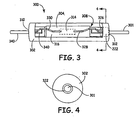
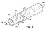
- pressure sensor module 300 includes a feedthrough pin 301, a capsule 302 having a cavity 308 therein, a pressure transducer 304, conductors 328 and 330 (e.g. a conductive ribbon), and an outer sheath 344 (shown in FIG. 5 ).
- feedthrough pin 301 extends into cavity 308, and pressure transducer 304 is positioned within cavity 308.
- Feedthrough pin 301 is insulated from capsule 302 by means of an insulative ferrule 322 (e.g. glass, plastic, etc.) that is provided through an end wall 312 of capsule 302.
- an insulative ferrule 322 e.g. glass, plastic, etc.
- capsule 302, ferrule 322, and feedthrough pin 301 provide a rigid structure whether formed integrally or formed separately and subsequently assembled.
- a second feedthrough pin 340 may be provided through an opposite end wall 310 of capsule 302 in a similar manner.
- Wire conductor coils 202 and 204 ( FIG. 2 ) may be electrically coupled to feedthrough pins 301 and 340.
- Capsule 302 may be formed of any suitable biocompatible material, such as titanium, or a biocompatible polymer. It should also be appreciated that while capsule 302 has been shown as an elongated tube, it may have any other suitable configuration.
- Pressure transducer 304 includes an integrated circuit 314 on a substrate 316.
- Circuit 314 is configured to convert sensed pressure into representative electrical signals and may comprise a MEMS integrated circuit chip, discrete passive electrical components, etc.
- Circuit 314 is electrically coupled to feedthrough pins 301 and 340 by means of flexible conductors 328 and 330, respectively (e.g. titanium, niobium, or platinum wires or ribbons), using known bonding techniques; e.g. laser welding, wire bonding, etc.
- pressure transducer 304 is not coupled or attached to any other portion of capsule 302, and except for its attachment to conductors 328 and 330, pressure transducer 304 is effectively suspended within cavity 308.
- cavity 308 may be filled with a biocompatible substance, not shown, such as deionized watch, saline, silicone gel or the like, preferably a material that absorbs body electrolytes.
- a biocompatible substance such as deionized watch, saline, silicone gel or the like, preferably a material that absorbs body electrolytes.
- pressure transducer 304 may be provided with a passivating layer (also not shown) for further protection. This passivating layer may comprise any one of a number of materials suitable for such purposes.
- transducer 304 is provided with non-hermetic strain relief that is further enhanced through the use of a biocompatible material within cavity 308. That is, forces that are exerted on feedthrough pins 301 and 340 are transferred to capsule 302 and not to transducer 304. Furthermore, any motion imparted to conductors 328 and 330 due to such forces is cushioned or absorbed by the media contained within cavity 308 and surrounding transducer 304.
- Feedthrough 301 electrically couples pressure transducer 304 to wire coil 202 to transmit a signal representative of pressure from integrated chip 314 to the non-illustrated implantable medical device.
- Feedthrough 301 is also configured to provide non-hermetic strain relief between pressure transducer 304 and lead 100 when module 300 is coupled to lead 100
- capsule 302 may include an outer housing 342 and an outer sheath 344.
- Outer housing 342 is configured to house capsule 302 therein and includes one or more openings 346 therethrough that communicate with cavity 308.
- Outer housing 342 may be constructed of any one of a number of suitable materials as previously described.
- outer sheath 344 is a sleeve that covers outer housing 342.
- outer sheath 344 is a flexible diaphragm configured to be disposed over openings 346.
- outer sheath 344 is constructed of a biocompatible material that is flexible and responsive to pressure exerted thereon; for example, polyurethane or silicone. Biocompatible media is held within cavity 308 by outer housing 342 and outer sheath 344.
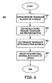
- FIG. 6 is a flow diagram 600 of an exemplary method for manufacturing the above-described pressure sensor module 300.
- pressure transducer 304 is flexibly mounted in cavity 308 of capsule 302 (step 602).
- transducer 304 and feedthrough pins 301 and 340 are electrically coupled to one another (step 604).
- Pressure transducer 304 may be coated with a passivating material to form a passivating layer (step 606), followed by depositing biocompatible material in cavity 308 (step 608).
- pressure transducer 304 may be obtained from any one of numerous sources.
- pressure transducer 304 may be manufactured to include conductors 328 and/or 330 pre-bonded thereto, or alternatively, without pre-bonded conductors.
- pressure transducer 304 may comprise a standard off-the-shelf item obtained from any one of numerous sources.
- Capsule 302 first may be machined from an appropriate material to include end openings, and appropriately configured insulative ferrules each having a passageway therethrough inserted into the end openings. Conductive pins are then inserted through the insulative ferrules. Capsule 302 is then heated to affix the conductive pins to the insulative ferrules.
- the feedthrough pins 301 and 340 may be integrally formed as part of capsule 302.
- Pressure transducer 304 is flexibly mounted within cavity 308 by, for example, depositing biocompatible potting material to partially fill cavity 308, positioning pressure transducer 304 on the deposited potting material, and electrically coupling the pressure transducer to feedthrough pins 301 and 340 (step 604) by, for example, laser welding, wire bonding, soldering, parallel gap welding, and the like. If not already provided, a passivating layer may be deposited over pressure transducer 304 by, for example, the deposition of any suitable material (step 606). Finally, cavity 308 is substantially filled with biocompatible media (step 608).
- biocompatible material is gel-like, it may be deposited directly into cavity 308 via a dispenser and may be heated, cooled, or the like, in order to set module components therein.
- capsule 302 may be inserted into outer housing 342 and covered with outer sheath 344. If outer sheath 344 is a sleeve, outer housing 342 is inserted into outer sheath 344. If outer sheath 344 is a sheet of material, outer sheath 344 is placed over window 346 and coupled to outer housing 342. In either case, cavity 308 is sealed and biocompatible fluid may be introduce into cavity 308 via, for example, a fill port (not shown) that may be pre-machined into capsule 302.
- apparatus and methods have been provided for a relatively simple and inexpensive pressure monitoring device that is has a corrosion-resistant configuration and is capable of being implanted into a patient long-term.
- the apparatus provides accurate blood pressure measurements.
Landscapes
- Health & Medical Sciences (AREA)
- Life Sciences & Earth Sciences (AREA)
- Physics & Mathematics (AREA)
- Cardiology (AREA)
- Biomedical Technology (AREA)
- Molecular Biology (AREA)
- Vascular Medicine (AREA)
- Biophysics (AREA)
- Pathology (AREA)
- Engineering & Computer Science (AREA)
- General Physics & Mathematics (AREA)
- Heart & Thoracic Surgery (AREA)
- Medical Informatics (AREA)
- Physiology (AREA)
- Surgery (AREA)
- Animal Behavior & Ethology (AREA)
- General Health & Medical Sciences (AREA)
- Public Health (AREA)
- Veterinary Medicine (AREA)
- Measuring Pulse, Heart Rate, Blood Pressure Or Blood Flow (AREA)
- Electrotherapy Devices (AREA)
- Measuring Fluid Pressure (AREA)
Applications Claiming Priority (2)
| Application Number | Priority Date | Filing Date | Title |
|---|---|---|---|
| US11/096,150 US7231829B2 (en) | 2005-03-31 | 2005-03-31 | Monolithic integrated circuit/pressure sensor on pacing lead |
| PCT/US2006/010556 WO2006104831A1 (en) | 2005-03-31 | 2006-03-24 | Monolithic integrated circuit/pressure sensor on pacing lead |
Publications (2)
| Publication Number | Publication Date |
|---|---|
| EP1863382A1 EP1863382A1 (en) | 2007-12-12 |
| EP1863382B1 true EP1863382B1 (en) | 2011-03-16 |
Family
ID=36763166
Family Applications (1)
| Application Number | Title | Priority Date | Filing Date |
|---|---|---|---|
| EP06739376A Expired - Lifetime EP1863382B1 (en) | 2005-03-31 | 2006-03-24 | Monolithic integrated circuit/pressure sensor on pacing lead |
Country Status (7)
| Country | Link |
|---|---|
| US (2) | US7231829B2 (enExample) |
| EP (1) | EP1863382B1 (enExample) |
| JP (1) | JP2008535553A (enExample) |
| AT (1) | ATE501669T1 (enExample) |
| CA (1) | CA2600469A1 (enExample) |
| DE (1) | DE602006020701D1 (enExample) |
| WO (1) | WO2006104831A1 (enExample) |
Families Citing this family (17)
| Publication number | Priority date | Publication date | Assignee | Title |
|---|---|---|---|---|
| US7231829B2 (en) * | 2005-03-31 | 2007-06-19 | Medtronic, Inc. | Monolithic integrated circuit/pressure sensor on pacing lead |
| US9616223B2 (en) | 2005-12-30 | 2017-04-11 | Medtronic, Inc. | Media-exposed interconnects for transducers |
| US8135479B2 (en) | 2008-04-23 | 2012-03-13 | Medtronic, Inc. | Sensor assemblies for implantable medical electrical leads |
| US7591185B1 (en) * | 2008-04-23 | 2009-09-22 | Medtronic, Inc. | Pressure sensor configurations for implantable medical electrical leads |
| US20090320978A1 (en) * | 2008-06-27 | 2009-12-31 | Martinez Johnny C | Sound-emitting wallet |
| US8340767B2 (en) | 2008-08-12 | 2012-12-25 | Cardiac Pacemakers, Inc. | Implantable lead and coronary venous pressure sensor apparatus and method |
| US8125058B2 (en) * | 2009-06-10 | 2012-02-28 | Medtronic, Inc. | Faraday cage for circuitry using substrates |
| US8172760B2 (en) | 2009-06-18 | 2012-05-08 | Medtronic, Inc. | Medical device encapsulated within bonded dies |
| US8436251B2 (en) * | 2009-07-08 | 2013-05-07 | Medtronic, Inc. | Ribbon connecting electrical components |
| US20110144637A1 (en) | 2009-12-11 | 2011-06-16 | Medtronic Cryocath Lp | Vein Occlusion Devices and Methods for Catheter-Based Ablation |
| US8666505B2 (en) | 2010-10-26 | 2014-03-04 | Medtronic, Inc. | Wafer-scale package including power source |
| US8424388B2 (en) | 2011-01-28 | 2013-04-23 | Medtronic, Inc. | Implantable capacitive pressure sensor apparatus and methods regarding same |
| US9131858B2 (en) * | 2012-01-31 | 2015-09-15 | Medtronic, Inc. | Sensor over-mold shape |
| US9517032B2 (en) | 2012-01-31 | 2016-12-13 | Medtronic, Inc. | Sensor over-mold shape |
| US9005134B2 (en) | 2012-01-31 | 2015-04-14 | Medtronic, Inc. | Sensor over-mold shape |
| CN107569223A (zh) * | 2017-10-21 | 2018-01-12 | 深圳北芯生命科技有限公司 | 带显影环的血管内压力测量导管 |
| US12016529B2 (en) | 2018-12-20 | 2024-06-25 | Boston Scientific Scimed, Inc. | Endoscopic scope device with a sensor |
Family Cites Families (26)
| Publication number | Priority date | Publication date | Assignee | Title |
|---|---|---|---|---|
| JPS5029280B1 (enExample) * | 1973-01-13 | 1975-09-22 | ||
| JPS5921495B2 (ja) * | 1977-12-15 | 1984-05-21 | 株式会社豊田中央研究所 | 細管型圧力計 |
| JPS6080434A (ja) * | 1983-10-07 | 1985-05-08 | 株式会社豊田中央研究所 | 体内留置型血圧計 |
| US4825876A (en) * | 1988-02-23 | 1989-05-02 | Abbott Laboratories | Encapsulated blood pressure transducer |
| US5189777A (en) | 1990-12-07 | 1993-03-02 | Wisconsin Alumni Research Foundation | Method of producing micromachined differential pressure transducers |
| US5353800A (en) | 1992-12-11 | 1994-10-11 | Medtronic, Inc. | Implantable pressure sensor lead |
| WO1996007351A1 (en) | 1994-09-02 | 1996-03-14 | Cardiometrics, Inc. | Ultra miniature pressure sensor and guidewire using the same and method |
| EP0702221A3 (en) | 1994-09-14 | 1997-05-21 | Delco Electronics Corp | Sensor integrated on a chip |
| FI100918B (fi) | 1995-02-17 | 1998-03-13 | Vaisala Oy | Pintamikromekaaninen, symmetrinen paine-eroanturi |
| US5564434A (en) | 1995-02-27 | 1996-10-15 | Medtronic, Inc. | Implantable capacitive absolute pressure and temperature sensor |
| US5535752A (en) | 1995-02-27 | 1996-07-16 | Medtronic, Inc. | Implantable capacitive absolute pressure and temperature monitor system |
| JPH08254473A (ja) * | 1995-03-17 | 1996-10-01 | Tokai Rika Co Ltd | 圧力センサ |
| CA2176052A1 (en) | 1995-06-07 | 1996-12-08 | James D. Seefeldt | Transducer having a resonating silicon beam and method for forming same |
| US5853020A (en) | 1995-06-23 | 1998-12-29 | Widner; Ronald D. | Miniature combination valve and pressure transducer and system |
| US6012336A (en) | 1995-09-06 | 2000-01-11 | Sandia Corporation | Capacitance pressure sensor |
| JP3565982B2 (ja) * | 1996-05-08 | 2004-09-15 | 株式会社東海理化電機製作所 | センサ機能を備えたカテーテル |
| US5764994A (en) * | 1996-09-16 | 1998-06-09 | International Business Machines Corporation | Method and system for compressing compiled microcode to be executed within a data processing system |
| US5846205A (en) * | 1997-01-31 | 1998-12-08 | Acuson Corporation | Catheter-mounted, phased-array ultrasound transducer with improved imaging |
| US6248080B1 (en) | 1997-09-03 | 2001-06-19 | Medtronic, Inc. | Intracranial monitoring and therapy delivery control device, system and method |
| US6203523B1 (en) | 1998-02-02 | 2001-03-20 | Medtronic Inc | Implantable drug infusion device having a flow regulator |
| US6221024B1 (en) | 1998-07-20 | 2001-04-24 | Medtronic, Inc. | Implantable pressure sensor and method of fabrication |
| US6171253B1 (en) | 1999-05-04 | 2001-01-09 | Apex Medical, Inc. | Flat tube pressure sensor |
| US6453749B1 (en) * | 1999-10-28 | 2002-09-24 | Motorola, Inc. | Physical sensor component |
| SE0103471D0 (sv) | 2001-10-15 | 2001-10-15 | Silex Microsystems Ab Electrum | Pressure sensor |
| WO2004019773A1 (en) | 2002-08-27 | 2004-03-11 | Michigan State University | Implantable microscale pressure sensor system |
| US7231829B2 (en) * | 2005-03-31 | 2007-06-19 | Medtronic, Inc. | Monolithic integrated circuit/pressure sensor on pacing lead |
-
2005
- 2005-03-31 US US11/096,150 patent/US7231829B2/en not_active Expired - Fee Related
-
2006
- 2006-03-24 AT AT06739376T patent/ATE501669T1/de not_active IP Right Cessation
- 2006-03-24 EP EP06739376A patent/EP1863382B1/en not_active Expired - Lifetime
- 2006-03-24 WO PCT/US2006/010556 patent/WO2006104831A1/en not_active Ceased
- 2006-03-24 JP JP2008504170A patent/JP2008535553A/ja not_active Withdrawn
- 2006-03-24 DE DE602006020701T patent/DE602006020701D1/de not_active Expired - Lifetime
- 2006-03-24 CA CA002600469A patent/CA2600469A1/en not_active Abandoned
-
2007
- 2007-02-16 US US11/675,961 patent/US7318264B2/en not_active Expired - Lifetime
Also Published As
| Publication number | Publication date |
|---|---|
| DE602006020701D1 (de) | 2011-04-28 |
| US20070151351A1 (en) | 2007-07-05 |
| US7318264B2 (en) | 2008-01-15 |
| US20060219019A1 (en) | 2006-10-05 |
| WO2006104831A1 (en) | 2006-10-05 |
| EP1863382A1 (en) | 2007-12-12 |
| ATE501669T1 (de) | 2011-04-15 |
| JP2008535553A (ja) | 2008-09-04 |
| US7231829B2 (en) | 2007-06-19 |
| CA2600469A1 (en) | 2006-10-05 |
Similar Documents
| Publication | Publication Date | Title |
|---|---|---|
| US7318264B2 (en) | Monolithic integrated circuit/pressure sensor on pacing lead | |
| JP7650504B2 (ja) | 心臓補助システム用モータハウジングモジュール、ならびに心臓補助システム、および心臓補助システムを取り付ける方法 | |
| US6221024B1 (en) | Implantable pressure sensor and method of fabrication | |
| EP0047986B1 (en) | Integral hermetic implantable pressure transducer | |
| US8135479B2 (en) | Sensor assemblies for implantable medical electrical leads | |
| CA1326968C (en) | Disposable pressure transducer and disposable pressure transducer apparatus | |
| US7347826B1 (en) | Packaging sensors for long term implant | |
| AU651916B2 (en) | Apparatus for mounting a pressure transducer | |
| US6248080B1 (en) | Intracranial monitoring and therapy delivery control device, system and method | |
| US7162926B1 (en) | Lead embedded pressure sensor | |
| US5951487A (en) | Intracorporeal measuring system | |
| US4967755A (en) | Electromedical lead with pressure sensor | |
| WO2011146122A1 (en) | Materials and methods for insulating electronic components and devices | |
| US9616223B2 (en) | Media-exposed interconnects for transducers | |
| JP2008161667A (ja) | 生理的パラメータの測定用能動センサー、マイクロ電気機械システムまたは集積回路を内蔵した植え込み型生体適合性部品 | |
| EP4117509B1 (en) | Pressure sensor | |
| EP2142083A2 (en) | Layered structure for corrosion resistant interconnect contacts | |
| US7418868B1 (en) | Pressure sensor and method of fabricating such a module | |
| US9332923B2 (en) | Sensor element with an insulation layer | |
| CN224220129U (zh) | 微型探头及监测设备 | |
| US20120004526A1 (en) | Sensor assemblies formed of silicone rubber for implantable medical electrical leads |
Legal Events
| Date | Code | Title | Description |
|---|---|---|---|
| PUAI | Public reference made under article 153(3) epc to a published international application that has entered the european phase |
Free format text: ORIGINAL CODE: 0009012 |
|
| 17P | Request for examination filed |
Effective date: 20071010 |
|
| AK | Designated contracting states |
Kind code of ref document: A1 Designated state(s): AT BE BG CH CY CZ DE DK EE ES FI FR GB GR HU IE IS IT LI LT LU LV MC NL PL PT RO SE SI SK TR |
|
| 17Q | First examination report despatched |
Effective date: 20080304 |
|
| DAX | Request for extension of the european patent (deleted) | ||
| GRAP | Despatch of communication of intention to grant a patent |
Free format text: ORIGINAL CODE: EPIDOSNIGR1 |
|
| GRAS | Grant fee paid |
Free format text: ORIGINAL CODE: EPIDOSNIGR3 |
|
| GRAA | (expected) grant |
Free format text: ORIGINAL CODE: 0009210 |
|
| AK | Designated contracting states |
Kind code of ref document: B1 Designated state(s): AT BE BG CH CY CZ DE DK EE ES FI FR GB GR HU IE IS IT LI LT LU LV MC NL PL PT RO SE SI SK TR |
|
| REG | Reference to a national code |
Ref country code: GB Ref legal event code: FG4D |
|
| REG | Reference to a national code |
Ref country code: CH Ref legal event code: EP |
|
| REG | Reference to a national code |
Ref country code: IE Ref legal event code: FG4D |
|
| REF | Corresponds to: |
Ref document number: 602006020701 Country of ref document: DE Date of ref document: 20110428 Kind code of ref document: P |
|
| REG | Reference to a national code |
Ref country code: DE Ref legal event code: R096 Ref document number: 602006020701 Country of ref document: DE Effective date: 20110428 |
|
| REG | Reference to a national code |
Ref country code: NL Ref legal event code: VDEP Effective date: 20110316 |
|
| PG25 | Lapsed in a contracting state [announced via postgrant information from national office to epo] |
Ref country code: GR Free format text: LAPSE BECAUSE OF FAILURE TO SUBMIT A TRANSLATION OF THE DESCRIPTION OR TO PAY THE FEE WITHIN THE PRESCRIBED TIME-LIMIT Effective date: 20110617 Ref country code: SE Free format text: LAPSE BECAUSE OF FAILURE TO SUBMIT A TRANSLATION OF THE DESCRIPTION OR TO PAY THE FEE WITHIN THE PRESCRIBED TIME-LIMIT Effective date: 20110316 Ref country code: ES Free format text: LAPSE BECAUSE OF FAILURE TO SUBMIT A TRANSLATION OF THE DESCRIPTION OR TO PAY THE FEE WITHIN THE PRESCRIBED TIME-LIMIT Effective date: 20110627 Ref country code: LV Free format text: LAPSE BECAUSE OF FAILURE TO SUBMIT A TRANSLATION OF THE DESCRIPTION OR TO PAY THE FEE WITHIN THE PRESCRIBED TIME-LIMIT Effective date: 20110316 Ref country code: LT Free format text: LAPSE BECAUSE OF FAILURE TO SUBMIT A TRANSLATION OF THE DESCRIPTION OR TO PAY THE FEE WITHIN THE PRESCRIBED TIME-LIMIT Effective date: 20110316 |
|
| LTIE | Lt: invalidation of european patent or patent extension |
Effective date: 20110316 |
|
| PG25 | Lapsed in a contracting state [announced via postgrant information from national office to epo] |
Ref country code: AT Free format text: LAPSE BECAUSE OF FAILURE TO SUBMIT A TRANSLATION OF THE DESCRIPTION OR TO PAY THE FEE WITHIN THE PRESCRIBED TIME-LIMIT Effective date: 20110316 Ref country code: BG Free format text: LAPSE BECAUSE OF FAILURE TO SUBMIT A TRANSLATION OF THE DESCRIPTION OR TO PAY THE FEE WITHIN THE PRESCRIBED TIME-LIMIT Effective date: 20110616 Ref country code: CY Free format text: LAPSE BECAUSE OF FAILURE TO SUBMIT A TRANSLATION OF THE DESCRIPTION OR TO PAY THE FEE WITHIN THE PRESCRIBED TIME-LIMIT Effective date: 20110316 Ref country code: SI Free format text: LAPSE BECAUSE OF FAILURE TO SUBMIT A TRANSLATION OF THE DESCRIPTION OR TO PAY THE FEE WITHIN THE PRESCRIBED TIME-LIMIT Effective date: 20110316 Ref country code: FI Free format text: LAPSE BECAUSE OF FAILURE TO SUBMIT A TRANSLATION OF THE DESCRIPTION OR TO PAY THE FEE WITHIN THE PRESCRIBED TIME-LIMIT Effective date: 20110316 |
|
| PG25 | Lapsed in a contracting state [announced via postgrant information from national office to epo] |
Ref country code: BE Free format text: LAPSE BECAUSE OF FAILURE TO SUBMIT A TRANSLATION OF THE DESCRIPTION OR TO PAY THE FEE WITHIN THE PRESCRIBED TIME-LIMIT Effective date: 20110316 |
|
| PG25 | Lapsed in a contracting state [announced via postgrant information from national office to epo] |
Ref country code: EE Free format text: LAPSE BECAUSE OF FAILURE TO SUBMIT A TRANSLATION OF THE DESCRIPTION OR TO PAY THE FEE WITHIN THE PRESCRIBED TIME-LIMIT Effective date: 20110316 Ref country code: MC Free format text: LAPSE BECAUSE OF NON-PAYMENT OF DUE FEES Effective date: 20110331 Ref country code: PT Free format text: LAPSE BECAUSE OF FAILURE TO SUBMIT A TRANSLATION OF THE DESCRIPTION OR TO PAY THE FEE WITHIN THE PRESCRIBED TIME-LIMIT Effective date: 20110718 |
|
| REG | Reference to a national code |
Ref country code: CH Ref legal event code: PL |
|
| PG25 | Lapsed in a contracting state [announced via postgrant information from national office to epo] |
Ref country code: SK Free format text: LAPSE BECAUSE OF FAILURE TO SUBMIT A TRANSLATION OF THE DESCRIPTION OR TO PAY THE FEE WITHIN THE PRESCRIBED TIME-LIMIT Effective date: 20110316 Ref country code: CZ Free format text: LAPSE BECAUSE OF FAILURE TO SUBMIT A TRANSLATION OF THE DESCRIPTION OR TO PAY THE FEE WITHIN THE PRESCRIBED TIME-LIMIT Effective date: 20110316 Ref country code: RO Free format text: LAPSE BECAUSE OF FAILURE TO SUBMIT A TRANSLATION OF THE DESCRIPTION OR TO PAY THE FEE WITHIN THE PRESCRIBED TIME-LIMIT Effective date: 20110316 Ref country code: IS Free format text: LAPSE BECAUSE OF FAILURE TO SUBMIT A TRANSLATION OF THE DESCRIPTION OR TO PAY THE FEE WITHIN THE PRESCRIBED TIME-LIMIT Effective date: 20110716 |
|
| PG25 | Lapsed in a contracting state [announced via postgrant information from national office to epo] |
Ref country code: NL Free format text: LAPSE BECAUSE OF FAILURE TO SUBMIT A TRANSLATION OF THE DESCRIPTION OR TO PAY THE FEE WITHIN THE PRESCRIBED TIME-LIMIT Effective date: 20110316 |
|
| REG | Reference to a national code |
Ref country code: IE Ref legal event code: MM4A |
|
| PLBE | No opposition filed within time limit |
Free format text: ORIGINAL CODE: 0009261 |
|
| STAA | Information on the status of an ep patent application or granted ep patent |
Free format text: STATUS: NO OPPOSITION FILED WITHIN TIME LIMIT |
|
| PG25 | Lapsed in a contracting state [announced via postgrant information from national office to epo] |
Ref country code: CH Free format text: LAPSE BECAUSE OF NON-PAYMENT OF DUE FEES Effective date: 20110331 Ref country code: IE Free format text: LAPSE BECAUSE OF NON-PAYMENT OF DUE FEES Effective date: 20110324 Ref country code: LI Free format text: LAPSE BECAUSE OF NON-PAYMENT OF DUE FEES Effective date: 20110331 |
|
| 26N | No opposition filed |
Effective date: 20111219 |
|
| GBPC | Gb: european patent ceased through non-payment of renewal fee |
Effective date: 20110616 |
|
| PG25 | Lapsed in a contracting state [announced via postgrant information from national office to epo] |
Ref country code: DK Free format text: LAPSE BECAUSE OF FAILURE TO SUBMIT A TRANSLATION OF THE DESCRIPTION OR TO PAY THE FEE WITHIN THE PRESCRIBED TIME-LIMIT Effective date: 20110316 Ref country code: PL Free format text: LAPSE BECAUSE OF FAILURE TO SUBMIT A TRANSLATION OF THE DESCRIPTION OR TO PAY THE FEE WITHIN THE PRESCRIBED TIME-LIMIT Effective date: 20110316 |
|
| REG | Reference to a national code |
Ref country code: DE Ref legal event code: R097 Ref document number: 602006020701 Country of ref document: DE Effective date: 20111219 |
|
| PGFP | Annual fee paid to national office [announced via postgrant information from national office to epo] |
Ref country code: FR Payment date: 20120406 Year of fee payment: 7 |
|
| PG25 | Lapsed in a contracting state [announced via postgrant information from national office to epo] |
Ref country code: IT Free format text: LAPSE BECAUSE OF FAILURE TO SUBMIT A TRANSLATION OF THE DESCRIPTION OR TO PAY THE FEE WITHIN THE PRESCRIBED TIME-LIMIT Effective date: 20110316 |
|
| PG25 | Lapsed in a contracting state [announced via postgrant information from national office to epo] |
Ref country code: GB Free format text: LAPSE BECAUSE OF NON-PAYMENT OF DUE FEES Effective date: 20110616 |
|
| PGFP | Annual fee paid to national office [announced via postgrant information from national office to epo] |
Ref country code: DE Payment date: 20120328 Year of fee payment: 7 |
|
| PG25 | Lapsed in a contracting state [announced via postgrant information from national office to epo] |
Ref country code: LU Free format text: LAPSE BECAUSE OF NON-PAYMENT OF DUE FEES Effective date: 20110324 |
|
| PG25 | Lapsed in a contracting state [announced via postgrant information from national office to epo] |
Ref country code: TR Free format text: LAPSE BECAUSE OF FAILURE TO SUBMIT A TRANSLATION OF THE DESCRIPTION OR TO PAY THE FEE WITHIN THE PRESCRIBED TIME-LIMIT Effective date: 20110316 |
|
| PG25 | Lapsed in a contracting state [announced via postgrant information from national office to epo] |
Ref country code: HU Free format text: LAPSE BECAUSE OF FAILURE TO SUBMIT A TRANSLATION OF THE DESCRIPTION OR TO PAY THE FEE WITHIN THE PRESCRIBED TIME-LIMIT Effective date: 20110316 |
|
| REG | Reference to a national code |
Ref country code: FR Ref legal event code: ST Effective date: 20131129 |
|
| REG | Reference to a national code |
Ref country code: DE Ref legal event code: R119 Ref document number: 602006020701 Country of ref document: DE Effective date: 20131001 |
|
| PG25 | Lapsed in a contracting state [announced via postgrant information from national office to epo] |
Ref country code: DE Free format text: LAPSE BECAUSE OF NON-PAYMENT OF DUE FEES Effective date: 20131001 Ref country code: FR Free format text: LAPSE BECAUSE OF NON-PAYMENT OF DUE FEES Effective date: 20130402 |