EP1862531A1 - Wuerzepfanne mit Aussenkocher - Google Patents
Wuerzepfanne mit Aussenkocher Download PDFInfo
- Publication number
- EP1862531A1 EP1862531A1 EP06010673A EP06010673A EP1862531A1 EP 1862531 A1 EP1862531 A1 EP 1862531A1 EP 06010673 A EP06010673 A EP 06010673A EP 06010673 A EP06010673 A EP 06010673A EP 1862531 A1 EP1862531 A1 EP 1862531A1
- Authority
- EP
- European Patent Office
- Prior art keywords
- wort
- riser
- kettle
- inlet pipe
- wort kettle
- Prior art date
- Legal status (The legal status is an assumption and is not a legal conclusion. Google has not performed a legal analysis and makes no representation as to the accuracy of the status listed.)
- Granted
Links
- 238000000034 method Methods 0.000 claims abstract description 15
- 235000011194 food seasoning agent Nutrition 0.000 claims abstract description 8
- 230000003068 static effect Effects 0.000 claims description 8
- 230000000630 rising effect Effects 0.000 claims description 7
- 230000001174 ascending effect Effects 0.000 claims description 2
- QMMFVYPAHWMCMS-UHFFFAOYSA-N Dimethyl sulfide Chemical compound CSC QMMFVYPAHWMCMS-UHFFFAOYSA-N 0.000 description 15
- 238000010438 heat treatment Methods 0.000 description 10
- 238000010411 cooking Methods 0.000 description 8
- 238000009835 boiling Methods 0.000 description 5
- 125000003118 aryl group Chemical group 0.000 description 3
- 230000007423 decrease Effects 0.000 description 3
- 239000007788 liquid Substances 0.000 description 3
- 238000005086 pumping Methods 0.000 description 3
- 230000007704 transition Effects 0.000 description 3
- 101150006573 PAN1 gene Proteins 0.000 description 2
- 239000000470 constituent Substances 0.000 description 2
- 238000001704 evaporation Methods 0.000 description 2
- 230000008020 evaporation Effects 0.000 description 2
- 235000013405 beer Nutrition 0.000 description 1
- 230000009194 climbing Effects 0.000 description 1
- 238000010276 construction Methods 0.000 description 1
- 230000001419 dependent effect Effects 0.000 description 1
- 238000004519 manufacturing process Methods 0.000 description 1
- 239000002245 particle Substances 0.000 description 1
- 230000002093 peripheral effect Effects 0.000 description 1
- 108090000623 proteins and genes Proteins 0.000 description 1
- 102000004169 proteins and genes Human genes 0.000 description 1
- 239000007787 solid Substances 0.000 description 1
- 239000000126 substance Substances 0.000 description 1
- 239000010409 thin film Substances 0.000 description 1
- XLYOFNOQVPJJNP-UHFFFAOYSA-N water Substances O XLYOFNOQVPJJNP-UHFFFAOYSA-N 0.000 description 1
Images


Classifications
-
- C—CHEMISTRY; METALLURGY
- C12—BIOCHEMISTRY; BEER; SPIRITS; WINE; VINEGAR; MICROBIOLOGY; ENZYMOLOGY; MUTATION OR GENETIC ENGINEERING
- C12C—BEER; PREPARATION OF BEER BY FERMENTATION; PREPARATION OF MALT FOR MAKING BEER; PREPARATION OF HOPS FOR MAKING BEER
- C12C7/00—Preparation of wort
- C12C7/20—Boiling the beerwort
- C12C7/205—Boiling with hops
- C12C7/22—Processes or apparatus specially adapted to save or recover energy
-
- C—CHEMISTRY; METALLURGY
- C12—BIOCHEMISTRY; BEER; SPIRITS; WINE; VINEGAR; MICROBIOLOGY; ENZYMOLOGY; MUTATION OR GENETIC ENGINEERING
- C12C—BEER; PREPARATION OF BEER BY FERMENTATION; PREPARATION OF MALT FOR MAKING BEER; PREPARATION OF HOPS FOR MAKING BEER
- C12C13/00—Brewing devices, not covered by a single group of C12C1/00 - C12C12/04
- C12C13/02—Brew kettles
-
- C—CHEMISTRY; METALLURGY
- C12—BIOCHEMISTRY; BEER; SPIRITS; WINE; VINEGAR; MICROBIOLOGY; ENZYMOLOGY; MUTATION OR GENETIC ENGINEERING
- C12C—BEER; PREPARATION OF BEER BY FERMENTATION; PREPARATION OF MALT FOR MAKING BEER; PREPARATION OF HOPS FOR MAKING BEER
- C12C9/00—Methods specially adapted for the making of beerwort
- C12C9/02—Beerwort treatment; Boiling with hops; Hop extraction
Definitions
- the invention relates to a wort kettle with an external boiler and a method for wort boiling.
- An essential process in beer production is the brewhouse process for extracting wort.
- the wort obtained from the lauter tun must be boiled, whereby bitter and aromatic constituents of the hop are converted into the wort and at the same time proteins and undesired aromatic volatile constituents, for example DMS (dimethyl sulfide), can be eliminated or evaporated.
- DMS dimethyl sulfide
- the wort boiling takes place in a wort kettle.
- wort pans with internal stoves and wort pans with outdoor stove.
- the cooker is located in the wort kettle.
- the internal boiler is, for example, a tube bundle heat exchanger standing in the wort kettle, through which the wort rises vertically through the tubes.
- the wort In wort pans with external boiling, the wort is heated by an external cooker located outside the pan.
- the wort is constantly withdrawn from the bottom of the wort kettle and pumped for example by means of a pump through the outdoor boiler and fed again to the pan.
- the wort relaxes. This leads to a desired vigorous evaporation.
- tube bundle heat exchangers or plate heat exchangers are usually used here.
- Outside cookers in contrast to the Innenkochem have a number of advantages.
- the wort outlet temperature and circulation rate can be controlled accurately.
- the required heating surface or the dimensions of the outdoor cooker is arbitrary and not limited by the size of the pan. The size of the wort kettle can therefore be reduced.
- the wort kettle with an external boiler has the disadvantage that the wort supply in the wort kettle does not circulate sufficiently.
- the circulation pump is dimensioned so that the pan content is converted about eight times per hour can be. Nevertheless, this does not guarantee that each seasoning particle passes through the cooker eight times. In particular, in the lower and corner regions of the wort kettle no adequate circulation is guaranteed.
- phase cooking which is a prerequisite for energy-saving wort boiling.
- the power of the circulation pump and / or the heating power of the digester during the heating and cooking process is controlled and adjusted to a setpoint curve, such as in the EP 0875559 B1 is explained.
- the cooking process is performed in different phases, the heating power of the wort cooker is dependent on a difference between the setpoint and actual value.
- the heating power is low or not heated at all, there is the problem that the pan content is not sufficiently circulated, since the reduced heating power, the relaxation energy of the heated wort is not sufficient to ensure good circulation to care.
- the object of the present invention is to provide a wort kettle and a corresponding process which enable an improved circulation of the wort in the wort kettle, even during phase cooking.
- the wort from the wort stock can be used together with the wort From the outside of the cooker heated wort rise from the bottom of the pan and run down to the top of the riser to the surface of the wort supply, so that a sufficient circulation of the wort is guaranteed in the wort stock.
- the wort kettle according to the invention therefore has two circulating circuits, wherein on the one hand wort from the wort supply is fed to the outside cooker and the heated wort is fed to the wort supply again via the inlet pipe and the riser pipe, and on the other hand in a further cycle wort from the wort supply via the at least one suction opening together with the heated seasoning goes up.
- the suction takes place inter alia due to the static negative pressure in the liquid flowing through the riser and due to the expansion of the heated wort.
- the pumping capacity of a circulation pump can be reduced, the wort from the wort supply to the outside boiler feeds, which in turn is then fed to the wort kettle, while the heating power can be reduced.
- the cross-sectional area of the riser increases at least in sections above the at least one intake opening at the top.
- the upper end of the inlet pipe adjoins the lower end region of the riser in such a way that the at least one suction opening between the inlet pipe and the riser is formed.
- the fact that the inlet pipe adjoins the lower end region of the riser pipe may mean that the upper end of the inlet pipe and the lower end of the riser pipe lie substantially in one plane. However, it may also mean that the upper end of the inlet pipe slightly protrudes into the lower end portion of the riser or is slightly spaced.
- the at least one suction opening is formed between the lower end of the riser and the outer wall of the inlet tube and the lateral end region, respectively.
- the riser at the lower end has a flared collar, i.e., the flared collar surrounding the inlet tube in the upper region.
- the riser has a non-expanding lower portion, for example a cylindrical portion and an upper portion, the cross-sectional area of which increases toward the upper end of the riser.
- This arrangement has the advantage that the wort sucked into the riser through the suction holes can flow into the non-expanding lower portion at high speed, which in turn brings about a high dynamic pressure.
- This area is then followed by the widening section, where the dynamic pressure and thus the flow rate decreases, with the wort expanding.
- the combination of the non-expanding section and the expanding section allows for ideal suction of the wort from the wort supply through the at least one suction port into the riser, even when the outside kettle temperature is low.
- the upper portion is preferably formed as a tapered tube whose outer wall is inclined at an angle ⁇ of 5 to 15 °, preferably 6 to 10 ° to the central axis L of the riser.
- the inlet pipe has a smaller cross-sectional area in its upper end than the lower end of the riser.
- the ratio of the diameter D1 of the inlet pipe at its upper end to the diameter D2 at the lower end of the riser behaves as follows: D2 / D1 ⁇ 1.5-2.5, in particular D2 / D1 ⁇ 2.
- This arrangement thus represents a nozzle, wherein preferably the inlet pipe has a conical nozzle portion at its upper end.
- Such an arrangement brings a particularly efficient suction of the wort from the wort stock in the riser with it. Due to the reduced cross-section of the inlet pipe, the flow rate of the wort is increased, wherein due to the low static pressure wort is attracted to the riser, and then the wort in the upwards expanding riser expands. In particular, in combination with the expanding cross-sectional area of the riser, a very good circulation can be achieved even in non-heated phases. Encrustation of the outdoor cooker can thus be effectively prevented.
- the riser tube has at its upper end a peripheral ring, preferably annular screen.
- the screen area is e.g. from the upper end of the riser inclined downwards.
- a guide body which has a baffle surface, is preferably provided above the riser. The wort can then escape via the gap between the screen surface and the guide body.
- the construction according to the invention makes it possible for the riser pipe or the riser pipe to be fastened in a simple manner to the wort kettle bottom via fastening elements.
- the intake openings are located in the lower third of the wort kettle.
- sufficient circulation is also possible in the bottom area and bottom corner area of the wort kettle, so that the effectiveness of the process can be optimized.
- FIG. 5 shows the wort kettle 1 according to the invention, which has a feed for wort 2.
- the wort kettle is fed via the inlet 2 from the lauter tun or a feed tank (not shown) via the line 13 and an optionally provided wort heating device 3 wort for cooking.
- the wort kettle here has an Au ⁇ enkocher 7.
- the external boiler 7 is, for example, a shell-and-tube heat exchanger or a plate heat exchanger.
- the size and performance of the outdoor cooker 7 can be freely selected as a function of the wort volume in the wort kettle 1 and the desired cooking process, since the size of the outdoor cooker 7 is not limited to the existing place in the wort kettle, as is the case for example with wort pans with internal boiler is.
- the external boiler 7 is operated here by superheated steam or high-pressure hot water and has for this purpose a supply line 14a and a return line 14b.
- the external boiler 7 is controlled by a control, not shown, so that the wort can be heated in phases with different power.
- the wort kettle 1 has at least one wort outlet 10, 15, which is provided here in the pan bottom.
- the wort outlet 10, 15 is preferably located in the pan bottom 23, but in any case below the surface of the wort supply 30th
- the wort outlet 10, 15 is provided by the pump 11, preferably equipped with a frequency converter, the wort from the wort supply 30 to the external boiler 7.
- the wort which has passed through the external boiler 7 and was heated in the heated phase of the external boiler 7, for example, to a temperature above 100 ° C, is fed via a further line of the wort supply 5 in the wort kettle 1 and rises there, as follows is explained in more detail, via the inlet pipe 16 and the riser 18 in the wort kettle 1 upwards and passes over the upper end of the riser 18 on the surface of the wort supply 30. From the wort stock 30, the wort can then again, as described above, on the wort outlet 10, 15 the outdoor boiler 7 are recycled. Further, via the wort outlet 10, 15, the ready-cooked wort can be supplied by means of the pump 11 by switching the valve 6, for example, to a hot tub for hot dregs. At the upper end, i. the end opposite the drain, the wort kettle 1, a vapor pipe 8, through which the resulting vapor is derived and, for example, a vapor condenser 9 feeds.
- wort kettle 1 and the inlet and riser 16, 18 can be seen better.
- the wort supply 5, which feeds the wort kettle 1 heated by the external boiler 7 again, is connected to the inlet pipe 16, 18.
- the wort supply 5 and the inlet pipe is arranged in the pan bottom, but can just as well be arranged in the pan side wall.
- the wort supply should be arranged so that the suction opening 26 is arranged substantially in the lower third of the pan.
- the riser is formed in two parts, but this is not necessarily necessary.
- the inlet pipe 16 and the riser 18 are arranged centrally here.
- the inlet pipe 16 is secured in the wort pan bottom 23.
- the riser 18 is also secured to the pan bottom 23 via brackets 22.
- the inlet pipe 16 adjacent to the lower end portion of the riser 18, as for example, also from Fig. 4a and Fig. 4c shows.
- the inlet pipe 16 has at its upper end a smaller cross-sectional area than the riser 18 at its lower end.
- a downwardly extending laterally closed collar 4 is provided at the lower end of the riser pipe 18 .
- the inlet pipe 16 protrudes into the collar 4 or the sleeve 4.
- the inlet pipe 16 has a diameter D1 at its upper end, ie here at its upper end edge
- the riser pipe 18 has a diameter D2 at its lower end or here in the entire section 18a.
- the ratio of Diameter of the inlet pipe at its upper end D1 to the diameter D2 at the lower end of the riser behaves as follows: D2 / D1 ⁇ 1.5 to 2.5, in particular D2 / D1 ⁇ 2.
- the diameter D3 of the collar 4 at its the Inlet 5 facing end is denoted by D3, wherein the ratio of D3 / D2 in a range of 1.5 to 2.5, preferably ⁇ 2.
- the upper end ie here the upper end edge of the inlet pipe 16 and the lower end, ie, for example, the lower edge of the riser pipe 18a, substantially in a plane.
- the upper end of the inlet pipe 16 may also project slightly into the riser 18 in the lower region, as shown in Fig. 4b or be spaced slightly downwardly therefrom, as shown in Fig. 4c.
- the inlet pipe 16 may protrude, for example, by a distance h 1 in the riser 18, wherein h 1 ⁇ D1 ⁇ 10%. This also applies to the distance h 1, as shown in Figure 4c, between the lower end of the riser 18 and the upper end and the upper end edge of the inlet pipe 16.
- the inlet pipe 16 may, however, not further protrude into the riser 18 or be spaced , otherwise the suction function of the riser, as will be explained in more detail below, is no longer guaranteed.
- the inlet pipe 16 at its upper end a tapered nozzle portion 17, so that by narrowing the cross section, the speed of the flowing wort, or the dynamic pressure increases and the static pressure decreases.
- at least one suction port 26, which is here annular is formed between the lower end of the riser 18 and the upper end or the outer wall of the inlet pipe 16 so at least one suction port 26, which is here annular, is formed. Due to the low static pressure, wort can be sucked in from the wort reservoir 30 into the riser 18 independently via the suction opening 26, as shown by the arrows in FIGS. 1 and 5. The aspirated wort then rises together with the wort heated by the external boiler 7, as shown by the arrow in Fig. 1, in the riser 18 upwards.
- the riser 18 is here designed so that it widens at least in sections upwards, ie in the rising direction of the wort.
- the riser 18 only has a cylindrical portion 18a, to which, as is clear from Fig. 2, a flared portion 18b connects, the cross-sectional area increases toward the end of the riser 18 out.
- the dynamic pressure of the rising wort is large and thus the Flow rate.
- the section 18a can thus also be referred to as a speed range.
- the upper portion 18b is here designed as a tapered about the longitudinal axis L rotationally symmetrical tube whose outer wall is inclined at an angle ⁇ of 5 to 15 °, preferably 6 to 10 ° to the central axis L, as is clear from Figure 2.
- the extension of the riser 18 above the suction openings 26 has the advantage that the ascending wort can expand, which in turn favors the circulation, ie the suction of the wort.
- the lengths of the sections 18a and 18b are preferably substantially the same and deviate at most by 25% -50% from one another.
- an annular shield 19 is arranged around the riser 18.
- the screen is preferably arranged annularly on the circumference of the riser.
- the riser 18 opposite the guide body 20 is arranged, which has a substantially concave swirl surface 29.
- the guide body 20 protrudes laterally into the region of the screen 19, so that between the guide body 20 and the screen 19 of the outlet gap S is formed, through which the wort is passed to the outside.
- the gap is annular in this embodiment.
- the gap height can be adjusted, for example, via the device shown in FIG.
- the wort can be passed as a thin film to the outside and impinge on the surface of the wort supply 30 from above. Due to the enlarged surface unwanted substances such as DMS can be removed.
- the guide body 20 is preferably arranged on the hood 24 via a fastening 21 on the upper part of the wort pan 1.
- the suction openings 26 are preferably arranged in the lower third of the wort kettle 1, so that a sufficient circulation of the wort in the lower region of the wort kettle is possible. As shown by the arrows, wort can be sucked in in particular from the lower corner regions of the wort kettle 1 from the suction openings 26.
- the wort outlet 10, 15 is also provided in the lower region, ie here in the pan bottom 23, so that the wort pan 1 can also be used with small wort volumes or small bottoms.
- a control valve 40 is provided in front of the inlet 5.
- the speed or the pressure of the rising wort can be adjusted so that the speed of the wort at about 2 to 3 m / sec. lies.
- the pressure of the rising wort must be at least equal to the saturation vapor pressure of the wort, which corresponds to the temperature of the wort heated by the outer cooker 7, plus the static pressure of the wort above the valve 40, i. in the riser and inlet pipe correspond.
- the wort to be cooked can be passed via a line 13 from a lauter tun or a feed tank to a wort heating device 3, which preheats the wort. However, the wort does not need to be preheated.
- the wort is then introduced via an inlet 2 into the wort kettle 1 until a certain wort stock 30 is stored in the wort kettle 1.
- wort is fed from the wort supply 30 via the wort outlet 10, 15 and the pump 11 (valve 6 closed) into the external boiler 7, where it is heated to temperatures of more than 100 °, preferably 101-104 ° C.
- the wort heated by the external boiler 7 is then fed again to the wort kettle 1 from below via the wort feed 5.
- the heated by the Au- ⁇ cooker wort passes the inlet pipe 16 and rises, as shown in Fig. 1, in the arrow direction upwards. Due to the tapered nozzle portion 17 of the inlet pipe 16, the flow rate of the wort is increased due to the cross-sectional constriction, such that the dynamic pressure increases and the static pressure decreases.
- the wort passes through the conical nozzle section 17 and rises into the riser pipe 18. Due to the low static pressure of the flowing liquid, wort from the wort supply 30, as shown by the dashed arrows in FIG. 1, is sucked into the riser 18 independently through the suction opening 26. Thus, the wort is also in the lower part of the wort kettle 1 in motion and circulates.
- the sucked wort then rises together with the wort heated by the external boiler 7 in the riser pipe 18, for example initially in the cylindrically shaped section 18a, and then in the upwardly widening section 18b upwards. Due to the fact that the riser pipe 18 widens upwards in the climbing direction, the heated wort in the riser pipe 18 can continue to expand, which in turn favors the circulation of the wort.
- the riser pipe 18 bounces the wort on the guide body 20 and is guided by the gap S, which is formed between the guide body or baffle 20 and screen 19, laterally downwards, wherein the surface of the exiting liquid is increased, which in turn the evaporation of unwanted aroma components, eg DMS favored.
- the wort then runs down and falls onto the surface of the wort supply 30.
- two cycles result, as shown in particular in FIG. 5.
- the wort circulates through the outlet 10, 15 the external boiler 7, the wort supply 5 and the riser 16, 17 and the wort stock 30 in the circuit, as shown by the solid arrows.
- This principle has the advantage that, in particular in the lower bottom region of the wort kettle, sufficient circulation of the wort is ensured.
- the clever arrangement and the advantageous structure of the riser, i. of the riser and the inlet pipe also brings with it the advantage that even in unheated phases, i. if the wort is withdrawn via the wort outlet 10, 15 via the pump 11, but not or only moderately heated and then fed back through the inlet pipe 16, a sufficient circulation in the wort kettle 1 can be realized, even if no large thermal relaxation energy is available.
- the pumping power, the heating power and the process duration can be optimized by the present invention.
- the Brüdendampf can be derived via the vent tube 8 and fed to a condenser 9.
- the wort kettle has been described with a riser, which is formed in two parts. However, it is also possible to form the riser in one piece with corresponding intake openings 26.
- the riser 18 has a cylindrical portion 18a and a conically widening portion 18b located above the cylindrical portion 18a. It is essential that wort in the riser expand towards the top can, wherein in this embodiment, an increase in speed takes place in section 18a and in section 18b, the speed is reduced by increasing the volume.
Landscapes
- Chemical & Material Sciences (AREA)
- Organic Chemistry (AREA)
- Engineering & Computer Science (AREA)
- General Health & Medical Sciences (AREA)
- Food Science & Technology (AREA)
- Biochemistry (AREA)
- Bioinformatics & Cheminformatics (AREA)
- General Engineering & Computer Science (AREA)
- Health & Medical Sciences (AREA)
- Genetics & Genomics (AREA)
- Life Sciences & Earth Sciences (AREA)
- Wood Science & Technology (AREA)
- Zoology (AREA)
- Distillation Of Fermentation Liquor, Processing Of Alcohols, Vinegar And Beer (AREA)
- Cookers (AREA)
- Commercial Cooking Devices (AREA)
- Soy Sauces And Products Related Thereto (AREA)
Abstract
Description
- Die Erfindung betrifft eine Würzepfanne mit Außenkocher sowie ein Verfahren zum Würzekochen.
- Ein wesentlicher Prozess bei der Bierherstellung ist der Sudhausprozess zur Gewinnung von Würze. Dabei muss die vom Läuterbottich gewonnene Würze gekocht werden, wobei bittere und aromatische Bestandteile des Hopfens in die Würze überführt und gleichzeitig Eiweißstoffe sowie nicht erwünschte aromatische flüchtige Bestandteile, beispielsweise DMS (Dimethylsulfid) ausgeschieden bzw. ausgedampft werden können.
- Das Würzekochen erfolgt in einer Würzepfanne. Grundsätzlich gibt es Würzepfannen mit Innenkocher sowie Würzepfannen mit Außenkocher. Bei den Würzepfannen mit Innenkocher befindet sich der Kocher in der Würzepfanne. Der Innenkocher ist dabei beispielsweise ein in der Würzepfanne stehender Rohrbündelwärmetauscher, durch dessen senkrecht angeordnete Rohre die Würze emporsteigt.
- Bei Würzepfannen mit Außenkochung wird die Würze über einen außerhalb der Pfanne angeordneten Außenkocher erhitzt. Dabei wird die Würze ständig aus dem Unterteil der Würzepfanne abgezogen und beispielsweise mittels einer Pumpe durch den Außenkocher gepumpt und erneut der Pfanne zugeführt. Bei der Rückführung in die Pfanne entspannt sich die Würze. Dabei kommt es zu einer erwünschten kräftigen Ausdampfung. Als Außenkocher werden auch hier zumeist Rohrbündelwärmetauscher oder aber Plattenwärmeüberträger verwendet. Außenkocher weisen im Gegensatz zu den Innenkochem eine Reihe von Vorteilen auf. Die Würzeaustrittstemperatur und Umwälzmenge kann genau geregelt werden. Die benötigte Heizfläche bzw. die Dimensionierung des Außenkochers ist frei wählbar und nicht durch die Größe der Pfanne begrenzt. Die Größe der Würzepfanne kann daher reduziert werden.
- Dennoch bringt die Würzepfanne mit Außenkocher den Nachteil mit sich, dass der Würzevorrat in der Würzepfanne nicht ausreichend zirkuliert. Zwar ist beispielsweise die Umwälzpumpe so dimensioniert, dass der Pfanneninhalt etwa achtmal je Stunde umgesetzt werden kann. Trotzdem wird dadurch nicht gewährleistet, dass jedes Würzeteilchen achtmal den Kocher durchläuft. Insbesondere in den unteren und Eckbereichen der Würzepfanne ist keine ausreichende Zirkulation gewährleistet.
- Insbesondere ergeben sich hier Probleme beim Phasenkochen, was Voraussetzung ist für ein energiesparendes Würzekochen. Beim Phasenkochen wird beispielsweise die Leistung der Umwälzpumpe und/oder die Heizleistung des Kochers während des Aufheiz- und Kochprozesses geregelt und einer Sollwertkurve angepasst, wie beispielsweise in der
EP 0875559 B1 erläutert wird. Hier wird also der Kochprozess in verschiedenen Phasen durchgeführt, wobei die Heizleistung des Würzekochers abhängig von einer Differenz zwischen Soll- und Istwert ist. Insbesondere in den Phasen, in denen die Heizleistung gering ist oder aber gar nicht geheizt wird, ergibt sich das Problem, dass der Pfanneninhalt nicht ausreichend umgewälzt wird, da durch die herabgesetzte Heizleistung die Entspannungsenergie der aufgeheizten Würze nicht ausreichend ist, um für eine gute Zirkulation zu sorgen. - Insgesamt ist bei den bekannten Würzepfannen und Würzekochverfahren eine hohe Pumpleistung nötig, die zu einer Durchlaufgeschwindigkeit von ca. 2 bis 3 m/sek. in den Außenkocherrohren führt, da es sonst zu Verkrustungen kommt.
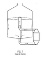
- Es wurde auch bereits vorgeschlagen, wie in der Figur 7 dargestellt ist, dass die von einem Außenkocher erhitzte Würze durch ein Einlaufrohr, das in ein Steigrohr ragt, zugeführt wird. Auch bei diesem System hat sich jedoch gezeigt, dass es insbesondere beim Phasenkochen zu keiner ausreichenden Zirkulation der Würze kommt.
- Hiervon ausgehend liegt der vorliegenden Erfindung die Aufgabe zugrunde, eine Würzepfanne und ein entsprechendes Verfahren bereitzustellen, die eine verbesserte Zirkulation der Würze in der Würzepfanne, selbst beim Phasenkochen ermöglichen.
- Erfindungsgemäß wird diese Aufgabe durch die Merkmale der Ansprüche 1 und 13 gelöst.
- Da gemäß der vorliegenden Erfindung zwischen Einlaufrohr und Steigrohr mindestens eine Ansaugöffnungvorgesehen ist, die die Würze aus einem Würzevorrat der Würzepfanne selbständig ansaugt, kann die Würze aus dem Würzevorrat zusammen mit der vom Außenkocher erhitzten Würze vom Pfannenboden nach oben steigen und zum oberen Ende des Steigrohrs auf die Oberfläche des Würzevorrats herab laufen, so dass eine ausreichende Zirkulation der Würze im Würzevorrat gewährleistet ist. Die erfindungsgemäße Würzepfanne weist somit zwei Zirkulierkreisläufe auf, wobei einerseits Würze aus dem Würzevorrat dem Außenkocher zugeführt und die erhitzte Würze dem Würzevorrat erneut über das Einlaufrohr und das Steigrohr zugeführt wird, und andererseits in einem weiteren Kreislauf Würze aus dem Würzevorrat über die mindestens eine Ansaugöffnung zusammen mit der erhitzten Würze nach oben steigt. Das Ansaugen erfolgt unter anderem aufgrund des statischen Unterdrucks in der durch die Steigleitung strömenden Flüssigkeit sowie aufgrund der Expansion der erhitzten Würze.
- Durch die verbesserte Zirkulation in der Würzepfanne kann daher auch die Pumpleistung einer Zirkulationspumpe herabgesetzt werden, die Würze aus dem Würzevorrat dem Außenkocher zuführt, die dann wiederum der Würzepfanne zugeführt wird, und dabei die Heizleistung herabgesetzt werden.
- Gemäß der Erfindung können somit auch besonders gut unerwünschte aromatische Komponenten und insbesondere DMS ausgetrieben werden.
- Gemäß der Erfindung vergrößert sich die Querschnittsfläche des Steigrohrs oberhalb der mindestens einen Ansaugöffnung nach oben hin zumindest abschnittsweise. Durch die Erweiterung der Steigleitung kann so die aufsteigende Würze expandieren, was die Zirkulation der Würze aus dem Würzevorrat in die Ansaugöffnungen weiter begünstigt. Durch die Zirkulation ist eine noch bessere Umwälzung möglich, insbesondere bei nicht beheizten Phasen, wenn es keine ausreichende thermische Entspannungsenergie gibt.
- Gemäß der Erfindung grenzt das obere Ende des Einlaufrohrs an den unteren Endbereich des Steigrohrs und zwar derart, dass die mindestens eine Ansaugöffnung zwischen dem Einlaufrohr und dem Steigrohr gebildet wird. Dass das Einlaufrohr an den unteren Endbereich des Steigrohrs angrenzt kann bedeuten, dass das obere Ende des Einlaufrohrs und das untere Ende des Steigrohrs im Wesentlichen in einer Ebene liegen. Es kann jedoch auch bedeuten, dass das obere Ende des Einlaufrohrs geringfügig in den unteren Endbereich des Steigrohrs ragt oder geringfügig beabstandet ist. So ist die mindestens eine Ansaugöffnung zwischen dem unteren Ende des Steigrohrs und der Au-βenwand des Einlaßrohrs bzw. dem seitlichen Endbereich gebildet.
- Vorteilhafterweise weist das Steigrohr am unteren Ende einen sich nach unten erweiternden Kragen auf, d.h., dass der erweiternde Kragen das Einlaufrohr im oberen Bereich umgibt.
- Vorteilhafterweise weist das Steigrohr einen sich nicht erweiternden unteren Abschnitt, beispielsweise einen zylindrischen Abschnitt und einen oberen Abschnitt, dessen Querschnittsfläche sich zum oberen Ende des Steigrohrs vergrößert. Diese Anordnung bringt den Vorteil mit sich, dass die Würze, die durch die Ansaugöffnungen in das Steigrohr angesaugt wird, in den sich nicht erweiternden unteren Abschnitt mit hoher Geschwindigkeit strömen kann, was wiederum einen hohen dynamischen Druck mit sich bringt. Nach diesem Bereich folgt dann der sich erweiternde Abschnitt, in dem der dynamische Druck und somit die Strömungsgeschwindigkeit abnimmt, wobei die Würze expandiert. Die Kombination aus dem sich nicht erweiternden Abschnitt und dem sich erweiternden Abschnitt ermöglicht ein ideales Ansaugen der Würze aus dem Würzevorrat durch die mindestens eine Ansaugöffnung in das Steigrohr, auch wenn die Außenkochertemperatur niedrig ist.
- Dabei ist der obere Abschnitt vorzugsweise als konisch zulaufendes Rohr ausgebildet, dessen Außenwandung unter einem Winkel β von 5 bis 15°, vorzugsweise 6 bis 10° zur Mittelachse L des Steigrohrs geneigt ist.
- Dabei weist das Einlaufrohr in seinem oberen Ende eine geringere Querschnittsfläche auf als das untere Ende des Steigrohrs.
- Es ist vorteilhaft, wenn das Verhältnis der Durchmesser D1 des Einlaufrohrs an seinem oberen Ende zu dem Durchmesser D2 am unteren Ende des Steigrohrs sich wie folgt verhält: D2/D1 ≅ 1,5 - 2,5, insbesondere D2/D1 ≅ 2.
- Diese Anordnung stellt somit eine Düse dar, wobei vorzugsweise das Einlaufrohr an seinem oberen Ende einen konischen Düsenabschnitt aufweist. Eine solche Anordnung bringt ein besonders effizientes Ansaugen der Würze aus dem Würzevorrat in das Steigrohr mit sich. Durch den verringerten Querschnitt des Einlaufrohrs wird die Flussgeschwindigkeit der Würze erhöht, wobei aufgrund des niedrigen statischen Drucks Würze in das Steigrohr angezogen wird, wobei anschließend die Würze in der sich nach oben erweiternden Steigleitung expandiert. Insbesondere in Kombination mit der sich erweiternden Querschnittsfläche des Steigrohrs kann auch in nicht beheizten Phasen eine sehr gute Umwälzung erzielt werden. Eine Verkrustung des Außenkochers kann somit wirksam verhindert werden.
- Es ist vorteilhaft, wenn das Steigrohr an seinem oberen Ende einen an seinem Umfang umlaufenden vorzugsweise ringförmigen Schirm aufweist. Dabei ist die Schirmfläche z.B. von dem oberen Ende des Steigrohrs nach unten geneigt. Somit kann die aus der Steigleitung bzw. dem Steigrohr nach oben austretende Würze seitlich umgelenkt werden, was die Oberfläche der Würze vergrößert, was letztendlich das Austreiben von unerwünschten Komponenten begünstigt. Dabei ist vorzugsweise oberhalb des Steigrohrs ein Leitkörper, der eine Prallfläche aufweist, vorgesehen. Die Würze kann dann über den Spalt zwischen Schirmfläche und Leitkörper austreten.
- Der erfindungsgemäße Aufbau ermöglicht, dass die Steigleitung oder das Steigrohr über Befestigungselemente in einfacher Weise an dem Würzepfannenboden befestigt werden kann.
- Vorzugsweise befinden sich die Ansaugöffnungen im unteren Dritten der Würzepfanne. Somit ist eine ausreichende Zirkulation auch in dem Bodenbereich und Bodeneckbereich der Würzepfanne möglich, so dass die Effektivität des Prozesses optimiert werden kann.
- Die vorliegende Erfindung wird nachfolgend unter Bezugnahme der folgenden Zeichnungen näher erläutert. Dabei zeigt
- Fig. 1
- schematisch einen Längsschnitt der Ausführungsform der vorliegenden Erfindung,
- Fig. 2
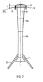
- einen Längsschnitt eines Steigrohrs gemäß der vorliegenden Erfindung,
- Fig. 3
- eine Aufsicht auf einen Schirm, der oben am Steigrohr angeordnet ist,
- Fig. 4a
- schematisch einen Ausschnitt, der den Übergang zwischen Einlaufrohr und Steigrohr gemäß der vorliegenden Erfindung zeigt,
- Fig. 4b
- schematisch den Übergang zwischen Einlaufrohr und Steigrohr gemäß der vorliegenden Erfindung,
- Fig. 4c
- schematisch den Übergang zwischen Einlaufrohr und Steigrohr,
- Fig. 5
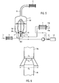
- schematisch die Würzepfanne mit Außenkocher,
- Fig. 6
- den in Fig. 4a gezeigten Ausschnitt mit entsprechender Bemaßung,
- Fig. 7
- eine Würzepfanne gemäß dem Stand der Technik.
- Fig. 5 zeigt die erfindungsgemäße Würzepfanne 1, die einen Zulauf für Würze 2 aufweist. Der Würzepfanne wird über den Zulauf 2 aus dem Läuterbottich oder einem Vorlauftank (nicht dargestellt) über die Leitung 13 und eine optional vorgesehene Würzeaufheizvorrichtung 3 Würze zum Kochen zugeführt. Die Würzepfanne weist hier einen Au-βenkocher 7 auf. Der Außenkocher 7 ist beispielsweise ein Rohrbündelwärmetauscher oder ein Plattenwärmeüberträger. Die Größe und Leistung des Außenkochers 7 kann in Abhängigkeit des Würzevolumens in der Würzepfanne 1 und des gewünschten Kochprozesses frei gewählt werden, da die Größe des Außenkochers 7 nicht auf den in der Würzepfanne vorhandenen Platz beschränkt ist, wie es beispielsweise bei Würzepfannen mit Innenkocher der Fall ist. Der Außenkocher 7 wird hier durch Heißdampf oder Hochdruckheißwasser betrieben und weist dafür eine Zuleitung 14a und eine Rückleitung 14b auf. Der Außenkocher 7 wird durch eine nicht dargestellte Steuerung angesteuert, so dass die Würze phasenweise mit unterschiedlicher Leistung beheizt werden kann. Die Würzepfanne 1 weist mindestens einen Würzeauslass 10, 15 auf, der hier im Pfannenboden vorgesehen ist. Der Würzeauslass 10, 15 befindet sich vorzugsweise im Pfannenboden 23, auf jeden Fall jedoch unterhalb der Oberfläche des Würzevorrats 30.
- In diesem Ausführungsbeispiel gibt es den Würzeauslass 10 und den Würzeauslass 15, die beide zusammengeführt werden.
- Über den Würzeauslass 10, 15 wird mittels der Pumpe 11, vorzugsweise mit Frequenzumformer ausgestattet, die Würze aus dem Würzevorrat 30 dem Außenkocher 7 zugeführt.
- Die Würze, die durch den Außenkocher 7 gelaufen ist und in der beheizten Phase von dem Außenkocher 7 beispielsweise auf eine Temperatur von über 100°C aufgeheizt wurde, wird über eine weitere Leitung der Würzezuführung 5 in der Würzepfanne 1 zugeleitet und steigt dort, wie nachfolgend noch näher erläutert wird, über das Einlaufrohr 16 und das Steigrohr18 in der Würzepfanne 1 nach oben und gelangt über das obere Ende des Steigrohrs18 auf die Oberfläche des Würzevorrats 30. Aus dem Würzevorrat 30 kann die Würze dann wieder, wie zuvor beschrieben, über den Würzeauslass 10, 15 dem Außenkocher 7 im Kreislauf zugeführt werden. Weiter kann über den Würzeauslass 10, 15die fertig gekochte Würze mittels der Pumpe 11 durch Schalten des Ventils 6 beispielsweise einem Whirlpool zur Heißtrubabscheidung zugeführt wird. Am oberen Ende, d.h. dem Ablauf entgegengesetzten Ende, weist die Würzepfanne 1 ein Dunstrohr 8 auf, durch das der entstehende Brüden abgeleitet und beispielsweise einem Brüdenkondensator 9 zuführt wird.
- In der Fig. 1 sind die Würzepfanne 1 sowie das Einlass- und Steigrohr 16, 18 besser zu erkennen. Die Würzezuführung 5, die von dem Außenkocher 7 erhitzte Würze erneut der Würzepfanne 1 zuführt, ist mit dem Einlassrohr 16, 18 verbunden. Hier ist die Würzezuführung 5 bzw. das Einlaufrohr im Pfannenboden angeordnet, kann aber genauso gut in der Pfannenseitenwand angeordnet sein. Die Würzezuführung sollte jedoch so angeordnet sein, dass die Ansaugöffnung 26 im Wesentlichen im unteren Drittel der Pfanne angeordnet ist. In diesem Ausführungsbeispiel ist die Steigleitung zweiteilig ausgebildet, was jedoch nicht zwangsläufig notwendig ist. Das Einlaufrohr 16 und das Steigrohr 18 sind hier zentrisch angeordnet. Das Einlaufrohr 16 ist im Würzepfanneboden 23 befestigt. Das Steigrohr 18 ist über Halterungen 22 ebenfalls an dem Pfannenboden 23 befestigt.
- Bei dieser Ausführungsform grenzt das Einlaufrohr 16 an den unteren Endbereich des Steigrohrs 18, wie beispielsweise auch aus Fig. 4a und Fig. 4c hervorgeht. Hier hat das Einlaufrohr 16 an seinem oberen Ende eine geringere Querschnittsfläche als das Steigrohr 18 an seinem unteren Ende. An das untere Ende des Steigrohrs 18a ist an sich nach unten erweiternder seitlich geschlossener Kragen 4 vorgesehen. Das Einlaufrohr 16 ragt in den Kragen 4 bzw. die Manschette 4 hinein. Wie besser aus Fig. 6 ersichtlich ist, weist das Einlaufrohr 16 an seinem oberen Ende, d.h. hier an seiner oberen Endkante, einen Durchmesser D1 auf und das Steigrohr 18 weist an seinem unteren Ende bzw. hier im gesamten Abschnitt 18a einen Durchmesser D2 auf, wobei das Verhältnis der Durchmesser des Einlaufrohrs an seinem oberen Ende D1 zu dem Durchmesser D2 am unteren Ende des Steigrohrs sich wie folgt verhält: D2/D1 ≅ 1,5 bis 2,5, insbesondere D2/D1 ≅ 2. Der Durchmesser D3 des Kragens 4 an seinem dem Einlauf 5 zugewandten Ende ist mit D3 bezeichnet, wobei das Verhältnis von D3/D2 in einem Bereich von 1,5 bis 2,5, vorzugsweise ≅ 2 liegt.
- In Fig. 4a liegen das obere Ende, d.h. hier die obere Endkante des Einlaufrohrs 16 und das untere Ende, d.h. beispielsweise die Unterkante des Steigrohrs 18a, im Wesentlichen in einer Ebene. Das obere Ende des Einlaufrohrs 16 kann jedoch auch geringfügig in das Steigrohr 18 in den unteren Bereich ragen, wie dies in Fig. 4b gezeigt ist oder aber von diesem geringfügig nach unten beabstandet sein, wie in Fig. 4c gezeigt ist. Dabei kann das Einlaufrohr 16 beispielsweise um eine Strecke h1 in das Steigrohr 18 ragen, wobei h1 < D1 ± 10% ist. Dies gilt auch für den Abstand h1 wie er in Figur 4c gezeigt ist, zwischen unterem Ende des Steigrohrs 18 und dem oberen Ende bzw. der oberen Endkante des Einlaufrohrs 16. Das Einlaufrohr 16 darf jedoch nicht weiter in das Steigrohr 18 ragen oder beabstandet sein, da sonst die Ansaugfunktion des Steigrohrs, wie nachfolgend noch näher erläutert wird, nicht mehr gewährleistet ist.
- In dieser Ausführungsform weist das Einlaufrohr 16 an seinem oberen Ende einen konisch zulaufenden Düsenabschnitt 17 auf, so dass durch Verengung des Querschnitts die Geschwindigkeit der durchströmenden Würze, bzw. der dynamische Druck zunimmt und der statische Druck abnimmt. Zwischen dem unteren Ende des Steigrohrs 18 und dem oberen Ende bzw. der Außenwand des Einlaufrohrs 16 bildet sich so mindestens eine Ansaugöffnung 26, die hier ringförmig ausgebildet ist, aus. Über die Ansaugöffnung 26 kann aufgrund des niedrigen statischen Druckes Würze aus dem Würzevorrat 30 in das Steigrohr 18 selbständig angesaugt werden, wie durch die Pfeile in Fig. 1 und 5 gezeigt ist. Die angesaugte Würze steigt dann zusammen mit der vom Außenkocher 7 erhitzten Würze, wie durch den Pfeil in Fig. 1 dargestellt ist, im Steigrohr 18 nach oben.
- Das Steigrohr 18 ist hier so ausgebildet, dass es sich zumindest abschnittsweise nach oben, d.h. in Steigrichtung der Würze erweitert. Hier weist das Steigrohr 18 erst einen zylindrischen Abschnitt 18a auf, an den sich, wie aus Fig. 2 deutlich wird, ein sich konisch erweiternder Abschnitt 18b anschließt, dessen Querschnittsfläche sich zum Ende des Steigrohrs 18 hin vergrößert. In dem sich nicht erweiternden Abschnitt 18a des Steigrohrs ist der dynamische Druck der aufsteigenden Würze groß und somit auch die Fließgeschwindigkeit. Der Abschnitt 18a kann somit auch als Geschwindigkeitsbereich bezeichnet werden. Der obere Abschnitt 18b ist hier als konisch zulaufendes um die Längsachse L rotationssymmetrisches Rohr ausgebildet, dessen Außenwandung unter einem Winkel β von 5 bis 15°, vorzugsweise 6 bis 10° zur Mittelachse L geneigt ist, wie aus Figur 2 deutlich wird. Die Erweiterung des Steigrohrs 18 oberhalb der Ansaugöffnungen 26 bringt den Vorteil mit sich, dass die aufsteigende Würze expandieren kann, was wiederum die Zirkulation, d.h. das Ansaugen der Würze, begünstigt. Die Längen der Abschnitte 18a und 18b sind vorzugsweise wesentlich gleich und weichen höchstens um 25% - 50% voneinander ab.
- Am oberen Ende des Steigrohrs 18 ist, wie insbesondere aus Fig. 2 und 3 hervorgeht, ein ringförmiger Schirm 19 um das Steigrohr 18 angeordnet. Der Schirm ist vorzugsweise ringförmig am Umfang des Steigrohrs angeordnet. Die Schirmfläche ist von dem oberen Ende des Steigrohrs 18 aus nach unten um einen Winkel α = 10 bis 40°, vorzugsweise 20 bis 30° zur Horizontalen geneigt. Dem Steigrohr 18 gegenüberliegend ist der Leitkörper 20 angeordnet, der eine im Wesentlichen konkave Drallfläche 29 aufweist.
Der Leitkörper 20 ragt seitlich bis in den Bereich des Schirms 19, so dass zwischen dem Leitkörper 20 und dem Schirm 19 der Austrittsspalt S gebildet wird, durch den die Würze nach außen geleitet wird. Der Spalt ist in diesem Ausführungsbeispiel ringförmig. Die Spalthöhe kann beispielsweise über die in Fig. 2 gezeigte Vorrichtung insbesondere Stellschraubvorrichtungen 27 verstellt werden. Somit kann die Würze als dünner Film nach außen geleitet werden und von oben auf die Oberfläche des Würzevorrats 30 auftreffen. Durch die vergrößerte Oberfläche können unerwünschte Stoffe beispielsweise DMS entfernt werden. Der Leitkörper 20 ist über eine Befestigung 21 am oberen Teil der Würzepfanne 1 vorzugsweise an der Haube 24 angeordnet. - Die Ansaugöffnungen 26 sind vorzugsweise im unteren Drittel der Würzepfanne 1 angeordnet, so dass eine ausreichende Zirkulierung der Würze im unteren Bereich der Würzepfanne möglich ist. Wie durch die Pfeile dargestellt wird, kann Würze insbesondere auch aus den unteren Eckbereichen der Würzepfanne 1 von den Ansaugöffnungen 26 angesaugt werden. In diesem Zusammenhang ist es insbesondere vorteilhaft, dass auch der Würzeauslass 10, 15 im unteren Bereich, d.h. hier im Pfannenboden 23 vorgesehen ist, so dass die Würzepfanne 1 auch bei kleinen Würzevolumina bzw. kleinen Suden verwendet werden kann.
- Wie aus Figur 5 hervorgeht, ist vor dem Einlass 5 ein Stellventil 40 vorgesehen. Über dieses Stellventil kann die Geschwindigkeit bzw. der Druck der aufsteigenden Würze eingestellt werden, so dass die Geschwindigkeit der Würze etwa bei 2 bis 3 m/sek. liegt. Auf jeden Fall muss der Druck der aufsteigenden Würze mindestens dem Sättigungsdampfdruck der Würze entsprechen, der mit der Temperatur der vom Außenkocher 7 erhitzten Würze korrespondiert, plus dem statischen Druck der Würze oberhalb des Ventils 40, d.h. im Steigrohr und Einlaufrohr entsprechen.
- Nachfolgend wird das erfindungsgemäße Verfahren für die in Zusammenhang mit Fig. 1 bis 5 gezeigte Würzepfanne näher erläutert.
- Zunächst kann die zu kochende Würze über eine Leitung 13 von einem Läuterbottich oder einem Vorlauftank aus zu einer Würzeaufheizvorrichtung 3 geleitet werden, die die Würze vorwärmt. Die Würze muss jedoch nicht vorgewärmt werden. Die Würze wird dann über einen Zulauf 2 in die Würzepfanne 1 eingeleitet, bis ein gewisser Würzevorrat 30 in der Würzepfanne 1 gelagert ist. Aus der Würzepfanne 1 wird aus dem Würzevorrat 30 über den Würzeauslass 10, 15 und die Pumpe 11 (Ventil 6 geschlossen) Würze in den Außenkocher 7 geleitet, wo sie auf Temperaturen von über 100°, vorzugsweise 101 -104°C erhitzt wird. Die vom Außenkocher 7 erhitzte Würze wird dann erneut der Würzepfanne 1 von unten über die Würzezuführung 5 zugeführt. Dabei passiert die vom Au-βenkocher erhitzte Würze das Einlaufrohr 16 und steigt, wie in Fig. 1 gezeigt, in Pfeilrichtung nach oben. Aufgrund des konisch zulaufenden Düsenabschnitts 17 des Einlaufrohrs 16 wird aufgrund der Querschnittsverengung die Fließgeschwindigkeit der Würze erhöht, derart, dass der dynamische Druck steigt und der statische Druck sinkt. Die Würze passiert den konischen Düsenabschnitt 17 und steigt in das Steigrohr 18 auf. Aufgrund des niedrigen statischen Drucks der strömenden Flüssigkeit wird Würze aus dem Würzevorrat 30, wie durch die gestrichelten Pfeile in Fig. 1 gezeigt, durch die Ansaugöffnung 26 selbständig in das Steigrohr 18 angesaugt. Somit kommt die Würze auch im unteren Bereich der Würzepfanne 1 in Bewegung und zirkuliert. Die angesaugte Würze steigt dann mit der von dem Außenkocher 7 erhitzten Würze zusammen im Steigrohr 18, z.B. zunächst im zylindrisch ausgebildeten Abschnitt 18a, und dann im sich nach oben erweiternden Abschnitt 18b nach oben. Dadurch, dass sich das Steigrohr 18 in Steigrichtung nach oben erweitert, kann die erhitzte Würze im Steigrohr 18 weiter expandieren, was wiederum die Zirkulation der Würze begünstigt. Am oberen Ende des Steigrohrs 18 prallt die Würze auf den Leitkörper 20 und wird durch den Spalt S, der zwischen Leitkörper bzw. Leitschirm 20 und Schirm 19 ausgebildet ist, seitlich nach unten geleitet, wobei die Oberfläche der austretenden Flüssigkeit vergrößert ist, was wiederum das Ausdampfen von unerwünschten Aromakomponenten, z.B. DMS begünstigt. Die Würze läuft dann nach unten und fällt auf die Oberfläche des Würzevorrats 30. Somit ergeben sich zwei Kreisläufe, wie insbesondere in Fig. 5 gezeigt ist. In einem Kreislauf zirkuliert die Würze über den Auslass 10, 15 den Außenkocher 7, der Würzezuführung 5 und der Steigleitung 16, 17 sowie den Würzevorrat 30 im Kreislauf, wie durch die durchgehenden Pfeile dargestellt.
- Andererseits ergibt sich ein weiterer Kreislauf, der in Fig. 5 gestrichelt dargestellt ist, wobei Würze über die mindestens eine Ansaugöffnung 26 in das Steigrohr 18 angesaugt wird, nach oben steigt, wieder dem Würzevorrat 30 zugeführt wird und erneut über die Ansaugöffnung 26 angesaugt wird.
- Dieses Prinzip bringt den Vorteil mit sich, dass insbesondere im unteren Bodenbereich der Würzepfanne eine ausreichende Zirkulation der Würze gewährleistet ist. Die geschickte Anordnung und der vorteilhafte Aufbau der Steigleitung, d.h. des Steigrohrs und des Einlaufrohrs bringt darüber hinaus den Vorteil mit sich, dass auch in nicht beheizten Phasen, d.h. wenn die Würze über den Würzeauslass 10, 15 über die Pumpe 11 abgezogen wird, jedoch nicht oder nur mäßig beheizt wird und dann wieder über das Einlaufrohr 16 zugeführt wird, eine ausreichende Zirkulierung in der Würzepfanne 1 realisiert werden kann, auch wenn keine große thermische Entspannungsenergie vorhanden ist. Insgesamt kann durch die vorliegende Erfindung die Pumpleistung, die Heizleistung und auch die Prozessdauer optimiert werden.
- Da zwischen 2 bis 4 % des Würzevolumens verdampft, kann der Brüdendampf über das Dunstrohr 8 abgeleitet und einem Kondensator 9 zugeführt werden.
- In diesem Ausführungsbeispiel wurde die Würzepfanne mit einer Steigleitung beschrieben, die zweiteilig ausgebildet ist. Es ist jedoch auch möglich, die Steigleitung einteilig mit entsprechenden Ansaugöffnungen 26 auszubilden. In der Ausführungsform, wie sie in Fig. 1 und 2 gezeigt ist, weist das Steigrohr 18 einen zylinderförmigen Abschnitt 18a und einen oberhalb des zylindrischen Abschnitts 18a angeordneten, sich konisch erweiternden Abschnitt 18b auf. Wesentlich ist, dass Würze im Steigrohr nach oben hin expandieren kann, wobei in diesem Ausführungsbeispiel im Abschnitt 18a eine Geschwindigkeitserhöhung erfolgt und im Abschnitt 18b die Geschwindigkeit durch Volumenvergrößerung reduziert wird.
Claims (15)
- Würzepfanne (1) mit
einem außerhalb der Würzepfanne (1) angeordneten Außenkocher (7), der im Kreislauf Würze aus der Würzepfanne (1) erhitzt, wobei die erhitzte Würze der Würzepfanne (1) erneut zugeführt wird,
einem Einlaufrohr (16) sowie einem über dem Einlaufrohr (16) angeordneten Steigrohr (18), durch die vom Außenkocher (7) erhitzte Würze in der Würzepfanne (1) nach oben steigt,
wobei das obere Ende des Einlaufrohrs (16) an den unteren Endbereich des Steigrohrs (18) derart angrenzt, dass mindestens eine Ansaugöffnung (26) zwischen dem Einlaufrohr (16) und dem Steigrohr (18) gebildet wird, zum Ansaugen von Würze aus einem Würzevorrat (30) der Würzepfanne, und
sich die Querschnittsfläche des Steigrohrs (18) zumindest abschnittsweise zum oberem Ende des Steigrohrs (18) hin vergrößert. - Würzepfanne nach Anspruch 1, dadurch gekennzeichnet, dass am unteren Ende des Steigrohrs (18) ein sich nach unten erweiternder Kragen (4) vorgesehen ist.
- Würzepfanne nach Anspruch 1 oder 2, dadurch gekennzeichnet, dass das Steigrohr (18) einen sich nicht erweiternden unteren Abschnitt (18a) aufweist und einen oberen Abschnitt (18b), dessen Querschnittsfläche sich zum oberen Ende des Steigrohrs (18) vergrößert.
- Würzepfanne nach Anspruch 3, dadurch gekennzeichnet, dass der obere Abschnitt (18b) als konisch zulaufendes Rohr ausgebildet ist, dessen Außenwandung unter einem Winkel β von 5 bis 15°, vorzugsweise 6 bis 10° zur Mittelachse L geneigt ist.
- Würzepfanne nach mindestens einem der Ansprüche 1 bis 4, dadurch gekennzeichnet, dass das Einlaufrohr (16) an seinem oberen Ende eine geringere Querschnittsfläche aufweist als das untere Ende des Steigrohrs (18).
- Würzepfanne nach Anspruch 5, dadurch gekennzeichnet, dass das Verhältnis der Durchmesser (D1) des Einlaufrohrs (16) an seinem oberen Ende zu dem Durchmesser (D2) am unteren Ende des Steigrohrs (D2) sich wie folgt verhält: D2/D1 = 1,5 bis 2,5, insbesondere D2/D1 - 2.
- Würzepfanne nach einem der Ansprüche 1 bis 6, dadurch gekennzeichnet, dass das Einlaufrohr (16) einen zu seinem oberen Ende hin zulaufenden konischen Düsenabschnitt (17) aufweist.
- Würzepfanne nach mindestens einem der Ansprüche 1 bis 7, dadurch gekennzeichnet, dass die mindestens eine Ansaugöffnung (26) im unteren Drittel der Würzepfanne angeordnet ist.
- Würzepfanne nach mindestens einem der vorhergehenden Patentansprüche, dadurch gekennzeichnet, dass die Steigleitung (16, 18) an dem oberen Ende einen an ihrem Umfang umlaufenden Schirm (19) aufweist.
- Würzepfanne nach Anspruch 9, dadurch gekennzeichnet, dass der Schirm (19) eine ringförmige Schirmfläche aufweist, die von dem oberen Ende der Steigleitung (16, 18) aus nach unten geneigt ist.
- Würzepfanne nach mindestens einem der Ansprüche 1 bis 10, dadurch gekennzeichnet, dass oberhalb der Steigleitung (18, 16) ein Leitkörper (20) angeordnet ist.
- Würzepfanne nach mindestens einem der Ansprüche 1 bis 11, dadurch gekennzeichnet, dass das Steigrohr (18) über Befestigungselemente (22) an dem Würzepfanneboden (23) befestigt ist.
- Verfahren zum Würze kochen mit einer Würzepfanne (1), wobei Würze aus der Würzepfanne (1) im Kreislauf von einem Außenkocher (7) erhitzt wird und die erhitzte Würze der Würzepfanne (1) erneut zugeführt wird, die vom Außenkocher (7) erhitzte Würze durch ein Einlaufrohr und ein darüber angeordnetes Steigrohr (18) in der Würzepfanne (1) nach oben steigt und vom oberen Ende des Steigrohrs (18) zu einem Würzevorrat (30) in der Würzepfanne herabläuft,
Würze aus dem Würzevorrat (30) über mindestens eine Ansaugöffnung (26) zwischen Einlaufrohr (16) und Steigrohr (18) selbständig in die Steigleitung (16) angesaugt wird und mit der vom Außenkocher erhitzten Würze nach oben steigt, wobei die aufsteigende Würze im sich zumindest abschnittsweise erweiternden Steigrohr (18) expandiert. - Verfahren nach Anspruch 13, dadurch gekennzeichnet, dass durch Verringerung der Querschnittsfläche des Einlaufrohrs (16) die Fließgeschwindigkeit der Würze erhöht und der statische Druck erniedrigt wird.
- Verfahren nach Anspruch 13 oder 14, dadurch gekennzeichnet, dass die aufsteigende Würze im Steigrohr (18) zunächst einen Abschnitt (18a) durchströmt, der sich nicht erweitert, gefolgt von einem Abschnitt (18b), der sich zum oberen Ende des Steigrohrs hin erweitert.
Priority Applications (9)
| Application Number | Priority Date | Filing Date | Title |
|---|---|---|---|
| AT06010673T ATE406434T1 (de) | 2006-05-23 | 2006-05-23 | Wuerzepfanne mit aussenkocher |
| DE502006001445T DE502006001445D1 (de) | 2006-05-23 | 2006-05-23 | Wuerzepfanne mit Aussenkocher |
| ES06010673T ES2312063T3 (es) | 2006-05-23 | 2006-05-23 | Caldera de coccion de mosto con calentador exterior. |
| EP06010673A EP1862531B1 (de) | 2006-05-23 | 2006-05-23 | Wuerzepfanne mit Aussenkocher |
| CA2626088A CA2626088C (en) | 2006-05-23 | 2007-03-06 | Wort copper with an external boiler |
| CN2007800173850A CN101443440B (zh) | 2006-05-23 | 2007-03-06 | 具有外部煮器的麦芽汁煮沸锅 |
| PCT/EP2007/001921 WO2007134657A1 (de) | 2006-05-23 | 2007-03-06 | Würzepfanne mit aussenkocher |
| JP2009511348A JP5009365B2 (ja) | 2006-05-23 | 2007-03-06 | 外部ボイラを有する麦汁釜 |
| US12/301,354 US8250968B2 (en) | 2006-05-23 | 2007-03-06 | Wort copper with an external boiler |
Applications Claiming Priority (1)
| Application Number | Priority Date | Filing Date | Title |
|---|---|---|---|
| EP06010673A EP1862531B1 (de) | 2006-05-23 | 2006-05-23 | Wuerzepfanne mit Aussenkocher |
Publications (2)
| Publication Number | Publication Date |
|---|---|
| EP1862531A1 true EP1862531A1 (de) | 2007-12-05 |
| EP1862531B1 EP1862531B1 (de) | 2008-08-27 |
Family
ID=37012007
Family Applications (1)
| Application Number | Title | Priority Date | Filing Date |
|---|---|---|---|
| EP06010673A Expired - Lifetime EP1862531B1 (de) | 2006-05-23 | 2006-05-23 | Wuerzepfanne mit Aussenkocher |
Country Status (9)
| Country | Link |
|---|---|
| US (1) | US8250968B2 (de) |
| EP (1) | EP1862531B1 (de) |
| JP (1) | JP5009365B2 (de) |
| CN (1) | CN101443440B (de) |
| AT (1) | ATE406434T1 (de) |
| CA (1) | CA2626088C (de) |
| DE (1) | DE502006001445D1 (de) |
| ES (1) | ES2312063T3 (de) |
| WO (1) | WO2007134657A1 (de) |
Cited By (1)
| Publication number | Priority date | Publication date | Assignee | Title |
|---|---|---|---|---|
| EP3020795A1 (de) * | 2014-11-11 | 2016-05-18 | Krones AG | Verfahren und vorrichtung zum würzekochen |
Families Citing this family (8)
| Publication number | Priority date | Publication date | Assignee | Title |
|---|---|---|---|---|
| DE102008056744A1 (de) * | 2008-11-11 | 2010-05-12 | Krones Ag | Vorrichtung und Verfahren zum Strippen von Würze |
| DE102009013579A1 (de) * | 2009-03-19 | 2010-09-23 | Gea Brewery Systems Gmbh | Brauereianlage zur Herstellung und Abfüllung von Bier |
| DE102009055300A1 (de) * | 2009-12-23 | 2011-06-30 | Krones Ag, 93073 | Vorrichtung und Verfahren zum Rückgewinnen von Energie |
| JP6045061B2 (ja) * | 2012-07-20 | 2016-12-14 | 株式会社三宅製作所 | 麦汁煮沸装置 |
| CN104531408B (zh) * | 2014-12-23 | 2017-04-26 | 宁波沪港食品机械制造有限公司 | 一种麦芽汁煮沸设备 |
| KR101549062B1 (ko) | 2015-04-03 | 2015-09-02 | 임윤환 | 맥즙 제조장치 |
| BE1024650B1 (fr) * | 2017-02-17 | 2018-05-15 | Meura S.A. | Dispositif et procédé pour le traitement thermique de moût |
| BE1027603B1 (nl) * | 2019-09-27 | 2021-04-26 | Brouwerij Cornelissen Bvpa | Brouwketel met afvoersysteem voor condens |
Citations (4)
| Publication number | Priority date | Publication date | Assignee | Title |
|---|---|---|---|---|
| GB1383330A (en) * | 1971-06-29 | 1974-02-12 | Briggs & Co Ltd | Cooking brewers wort |
| DE2535120A1 (de) * | 1975-08-06 | 1977-02-24 | Steinecker Maschf Anton | Verfahren und einrichtung zur behandlung von bierwuerze |
| DE19634010A1 (de) * | 1995-10-27 | 1997-04-30 | Steinecker Maschf Anton | Würzepfanne |
| WO2004092321A1 (de) * | 2003-04-15 | 2004-10-28 | Krones Ag | Vorrichtung und verfahren zur bierbereitung |
Family Cites Families (7)
| Publication number | Priority date | Publication date | Assignee | Title |
|---|---|---|---|---|
| JPH0347108A (ja) | 1989-04-05 | 1991-02-28 | Kao Corp | 二重乳化型化粧料組成物 |
| JPH0347108U (de) * | 1989-09-19 | 1991-05-01 | ||
| DE4019526A1 (de) * | 1990-06-19 | 1992-01-09 | Steinecker Anton Entwicklung | Wuerzekochvorrichtung mit aussenkocher |
| CA2234216C (en) | 1997-04-08 | 2007-06-12 | Anton Steinecker Maschinenfabrik Gmbh | A method and apparatus for heating and atmospherically boiling wort in the beer brewing process |
| JP2001335906A (ja) * | 2000-05-26 | 2001-12-07 | Nippon Steel Hardfacing Co Ltd | スナウト内異物除去装置 |
| JP4074809B2 (ja) * | 2002-11-29 | 2008-04-16 | 株式会社日本メディックス | 液体式マッサージ装置 |
| JP4354260B2 (ja) | 2003-11-27 | 2009-10-28 | 本田技研工業株式会社 | 流体輸送装置 |
-
2006
- 2006-05-23 AT AT06010673T patent/ATE406434T1/de active
- 2006-05-23 EP EP06010673A patent/EP1862531B1/de not_active Expired - Lifetime
- 2006-05-23 ES ES06010673T patent/ES2312063T3/es not_active Expired - Lifetime
- 2006-05-23 DE DE502006001445T patent/DE502006001445D1/de active Active
-
2007
- 2007-03-06 CN CN2007800173850A patent/CN101443440B/zh not_active Expired - Fee Related
- 2007-03-06 JP JP2009511348A patent/JP5009365B2/ja not_active Expired - Fee Related
- 2007-03-06 CA CA2626088A patent/CA2626088C/en not_active Expired - Fee Related
- 2007-03-06 WO PCT/EP2007/001921 patent/WO2007134657A1/de not_active Ceased
- 2007-03-06 US US12/301,354 patent/US8250968B2/en not_active Expired - Fee Related
Patent Citations (4)
| Publication number | Priority date | Publication date | Assignee | Title |
|---|---|---|---|---|
| GB1383330A (en) * | 1971-06-29 | 1974-02-12 | Briggs & Co Ltd | Cooking brewers wort |
| DE2535120A1 (de) * | 1975-08-06 | 1977-02-24 | Steinecker Maschf Anton | Verfahren und einrichtung zur behandlung von bierwuerze |
| DE19634010A1 (de) * | 1995-10-27 | 1997-04-30 | Steinecker Maschf Anton | Würzepfanne |
| WO2004092321A1 (de) * | 2003-04-15 | 2004-10-28 | Krones Ag | Vorrichtung und verfahren zur bierbereitung |
Cited By (1)
| Publication number | Priority date | Publication date | Assignee | Title |
|---|---|---|---|---|
| EP3020795A1 (de) * | 2014-11-11 | 2016-05-18 | Krones AG | Verfahren und vorrichtung zum würzekochen |
Also Published As
| Publication number | Publication date |
|---|---|
| WO2007134657A1 (de) | 2007-11-29 |
| DE502006001445D1 (de) | 2008-10-09 |
| CN101443440A (zh) | 2009-05-27 |
| JP2009537157A (ja) | 2009-10-29 |
| ES2312063T3 (es) | 2009-02-16 |
| CN101443440B (zh) | 2012-07-04 |
| US8250968B2 (en) | 2012-08-28 |
| JP5009365B2 (ja) | 2012-08-22 |
| CA2626088A1 (en) | 2007-11-29 |
| CA2626088C (en) | 2014-02-11 |
| ATE406434T1 (de) | 2008-09-15 |
| EP1862531B1 (de) | 2008-08-27 |
| US20090191321A1 (en) | 2009-07-30 |
Similar Documents
| Publication | Publication Date | Title |
|---|---|---|
| WO2007134657A1 (de) | Würzepfanne mit aussenkocher | |
| EP1088053B1 (de) | Gefäss und verfahren zur behandlung von würze bei der bierherstellung | |
| DE102008056744A1 (de) | Vorrichtung und Verfahren zum Strippen von Würze | |
| EP1469062B1 (de) | Vorrichtung und Verfahren zur Bierbereitung | |
| EP2220207B1 (de) | Vorrichtung und verfahren zum kontinuierlichen würzekochen | |
| DE3214065C1 (de) | Pfannendunst-Kondensator | |
| DE102008039374A1 (de) | Läuterverfahren | |
| DE102014116471A1 (de) | Verfahren und Vorrichtung zum Würzekochen | |
| DE10351426B3 (de) | Verfahren zum Kochen von Würze | |
| DE102005021782B4 (de) | Vorrichtung zum Aufheizen und Kochen von Bierwürze mit einem Innenkocher, insbesondere Röhrenkocher | |
| DE102011055146A1 (de) | Brauereianlage und Verfahren zur Erwärmung von Brau- und Brauchwasser in einer Brauereianlage | |
| EP2624945B1 (de) | Vorrichtung und verfahren zum erwärmen eines flüssigen mediums, insbesondere maischvorrichtung zum herstellen von bier | |
| DE202014105416U1 (de) | Vorrichtung zum Würzekochen | |
| DE3442516C1 (de) | Innenkocher, insbesondere Röhrenkocher zum Einbau in eine Würzepfanne | |
| EP1264876A2 (de) | Sudhausanlage und Komponenten einer Sudhausanlage, Verfahren zum Betrieb einer Sudhausanlage und deren Komponenten | |
| WO2001012773A2 (de) | Würzepfanne | |
| DE102015111837B3 (de) | Verfahren und Gefäß zum Wärmebehandeln einer Würze bei der Bier- oder Getränkeherstellung | |
| WO2013159918A1 (de) | Würzeausdampfvorrichtung | |
| DE2535120A1 (de) | Verfahren und einrichtung zur behandlung von bierwuerze | |
| DE3106875A1 (de) | Waermetauscher zur aufheizung von maische oder bierwuerze | |
| DE102019133438B3 (de) | Würzeaufheiz- und -kochvorrichtung und Verfahren zum Aufheizen von Würze | |
| DE102024115674A1 (de) | Vorrichtung und Verfahren zur Kochung von Würze | |
| DE2313932C3 (de) | Braukessel | |
| DE102009043923A1 (de) | Brauverfahren und Brauvorrichtung mit Verwendung eines Heißwasserkessels | |
| DE156022C (de) |
Legal Events
| Date | Code | Title | Description |
|---|---|---|---|
| PUAI | Public reference made under article 153(3) epc to a published international application that has entered the european phase |
Free format text: ORIGINAL CODE: 0009012 |
|
| GRAP | Despatch of communication of intention to grant a patent |
Free format text: ORIGINAL CODE: EPIDOSNIGR1 |
|
| 17P | Request for examination filed |
Effective date: 20061128 |
|
| AK | Designated contracting states |
Kind code of ref document: A1 Designated state(s): AT BE BG CH CY CZ DE DK EE ES FI FR GB GR HU IE IS IT LI LT LU LV MC NL PL PT RO SE SI SK TR |
|
| GRAS | Grant fee paid |
Free format text: ORIGINAL CODE: EPIDOSNIGR3 |
|
| GRAA | (expected) grant |
Free format text: ORIGINAL CODE: 0009210 |
|
| AKX | Designation fees paid |
Designated state(s): AT BE BG CH CY CZ DE DK EE ES FI FR GB GR HU IE IS IT LI LT LU LV MC NL PL PT RO SE SI SK TR |
|
| AK | Designated contracting states |
Kind code of ref document: B1 Designated state(s): AT BE BG CH CY CZ DE DK EE ES FI FR GB GR HU IE IS IT LI LT LU LV MC NL PL PT RO SE SI SK TR |
|
| REG | Reference to a national code |
Ref country code: GB Ref legal event code: FG4D Free format text: NOT ENGLISH |
|
| REG | Reference to a national code |
Ref country code: CH Ref legal event code: EP |
|
| REG | Reference to a national code |
Ref country code: IE Ref legal event code: FG4D Free format text: LANGUAGE OF EP DOCUMENT: GERMAN |
|
| REF | Corresponds to: |
Ref document number: 502006001445 Country of ref document: DE Date of ref document: 20081009 Kind code of ref document: P |
|
| PG25 | Lapsed in a contracting state [announced via postgrant information from national office to epo] |
Ref country code: LT Free format text: LAPSE BECAUSE OF FAILURE TO SUBMIT A TRANSLATION OF THE DESCRIPTION OR TO PAY THE FEE WITHIN THE PRESCRIBED TIME-LIMIT Effective date: 20080827 Ref country code: IS Free format text: LAPSE BECAUSE OF FAILURE TO SUBMIT A TRANSLATION OF THE DESCRIPTION OR TO PAY THE FEE WITHIN THE PRESCRIBED TIME-LIMIT Effective date: 20081227 Ref country code: NL Free format text: LAPSE BECAUSE OF FAILURE TO SUBMIT A TRANSLATION OF THE DESCRIPTION OR TO PAY THE FEE WITHIN THE PRESCRIBED TIME-LIMIT Effective date: 20080827 |
|
| REG | Reference to a national code |
Ref country code: ES Ref legal event code: FG2A Ref document number: 2312063 Country of ref document: ES Kind code of ref document: T3 |
|
| PG25 | Lapsed in a contracting state [announced via postgrant information from national office to epo] |
Ref country code: LV Free format text: LAPSE BECAUSE OF FAILURE TO SUBMIT A TRANSLATION OF THE DESCRIPTION OR TO PAY THE FEE WITHIN THE PRESCRIBED TIME-LIMIT Effective date: 20080827 Ref country code: FI Free format text: LAPSE BECAUSE OF FAILURE TO SUBMIT A TRANSLATION OF THE DESCRIPTION OR TO PAY THE FEE WITHIN THE PRESCRIBED TIME-LIMIT Effective date: 20080827 Ref country code: SI Free format text: LAPSE BECAUSE OF FAILURE TO SUBMIT A TRANSLATION OF THE DESCRIPTION OR TO PAY THE FEE WITHIN THE PRESCRIBED TIME-LIMIT Effective date: 20080827 |
|
| REG | Reference to a national code |
Ref country code: IE Ref legal event code: FD4D |
|
| PG25 | Lapsed in a contracting state [announced via postgrant information from national office to epo] |
Ref country code: IE Free format text: LAPSE BECAUSE OF FAILURE TO SUBMIT A TRANSLATION OF THE DESCRIPTION OR TO PAY THE FEE WITHIN THE PRESCRIBED TIME-LIMIT Effective date: 20080827 Ref country code: DK Free format text: LAPSE BECAUSE OF FAILURE TO SUBMIT A TRANSLATION OF THE DESCRIPTION OR TO PAY THE FEE WITHIN THE PRESCRIBED TIME-LIMIT Effective date: 20080827 Ref country code: BG Free format text: LAPSE BECAUSE OF FAILURE TO SUBMIT A TRANSLATION OF THE DESCRIPTION OR TO PAY THE FEE WITHIN THE PRESCRIBED TIME-LIMIT Effective date: 20081127 |
|
| PG25 | Lapsed in a contracting state [announced via postgrant information from national office to epo] |
Ref country code: PT Free format text: LAPSE BECAUSE OF FAILURE TO SUBMIT A TRANSLATION OF THE DESCRIPTION OR TO PAY THE FEE WITHIN THE PRESCRIBED TIME-LIMIT Effective date: 20090127 Ref country code: RO Free format text: LAPSE BECAUSE OF FAILURE TO SUBMIT A TRANSLATION OF THE DESCRIPTION OR TO PAY THE FEE WITHIN THE PRESCRIBED TIME-LIMIT Effective date: 20080827 Ref country code: SK Free format text: LAPSE BECAUSE OF FAILURE TO SUBMIT A TRANSLATION OF THE DESCRIPTION OR TO PAY THE FEE WITHIN THE PRESCRIBED TIME-LIMIT Effective date: 20080827 |
|
| PLBE | No opposition filed within time limit |
Free format text: ORIGINAL CODE: 0009261 |
|
| STAA | Information on the status of an ep patent application or granted ep patent |
Free format text: STATUS: NO OPPOSITION FILED WITHIN TIME LIMIT |
|
| PG25 | Lapsed in a contracting state [announced via postgrant information from national office to epo] |
Ref country code: EE Free format text: LAPSE BECAUSE OF FAILURE TO SUBMIT A TRANSLATION OF THE DESCRIPTION OR TO PAY THE FEE WITHIN THE PRESCRIBED TIME-LIMIT Effective date: 20080827 |
|
| 26N | No opposition filed |
Effective date: 20090528 |
|
| PG25 | Lapsed in a contracting state [announced via postgrant information from national office to epo] |
Ref country code: MC Free format text: LAPSE BECAUSE OF NON-PAYMENT OF DUE FEES Effective date: 20090531 |
|
| PG25 | Lapsed in a contracting state [announced via postgrant information from national office to epo] |
Ref country code: SE Free format text: LAPSE BECAUSE OF FAILURE TO SUBMIT A TRANSLATION OF THE DESCRIPTION OR TO PAY THE FEE WITHIN THE PRESCRIBED TIME-LIMIT Effective date: 20081127 |
|
| PG25 | Lapsed in a contracting state [announced via postgrant information from national office to epo] |
Ref country code: PL Free format text: LAPSE BECAUSE OF FAILURE TO SUBMIT A TRANSLATION OF THE DESCRIPTION OR TO PAY THE FEE WITHIN THE PRESCRIBED TIME-LIMIT Effective date: 20080827 |
|
| PG25 | Lapsed in a contracting state [announced via postgrant information from national office to epo] |
Ref country code: GR Free format text: LAPSE BECAUSE OF FAILURE TO SUBMIT A TRANSLATION OF THE DESCRIPTION OR TO PAY THE FEE WITHIN THE PRESCRIBED TIME-LIMIT Effective date: 20081128 |
|
| REG | Reference to a national code |
Ref country code: CH Ref legal event code: PL |
|
| PG25 | Lapsed in a contracting state [announced via postgrant information from national office to epo] |
Ref country code: LI Free format text: LAPSE BECAUSE OF NON-PAYMENT OF DUE FEES Effective date: 20100531 Ref country code: CH Free format text: LAPSE BECAUSE OF NON-PAYMENT OF DUE FEES Effective date: 20100531 |
|
| PG25 | Lapsed in a contracting state [announced via postgrant information from national office to epo] |
Ref country code: LU Free format text: LAPSE BECAUSE OF NON-PAYMENT OF DUE FEES Effective date: 20090523 |
|
| PG25 | Lapsed in a contracting state [announced via postgrant information from national office to epo] |
Ref country code: HU Free format text: LAPSE BECAUSE OF FAILURE TO SUBMIT A TRANSLATION OF THE DESCRIPTION OR TO PAY THE FEE WITHIN THE PRESCRIBED TIME-LIMIT Effective date: 20090228 |
|
| PG25 | Lapsed in a contracting state [announced via postgrant information from national office to epo] |
Ref country code: TR Free format text: LAPSE BECAUSE OF FAILURE TO SUBMIT A TRANSLATION OF THE DESCRIPTION OR TO PAY THE FEE WITHIN THE PRESCRIBED TIME-LIMIT Effective date: 20080827 |
|
| PG25 | Lapsed in a contracting state [announced via postgrant information from national office to epo] |
Ref country code: CY Free format text: LAPSE BECAUSE OF FAILURE TO SUBMIT A TRANSLATION OF THE DESCRIPTION OR TO PAY THE FEE WITHIN THE PRESCRIBED TIME-LIMIT Effective date: 20080827 |
|
| REG | Reference to a national code |
Ref country code: FR Ref legal event code: PLFP Year of fee payment: 10 |
|
| PGFP | Annual fee paid to national office [announced via postgrant information from national office to epo] |
Ref country code: ES Payment date: 20150413 Year of fee payment: 10 |
|
| PGFP | Annual fee paid to national office [announced via postgrant information from national office to epo] |
Ref country code: FR Payment date: 20150508 Year of fee payment: 10 Ref country code: AT Payment date: 20150427 Year of fee payment: 10 |
|
| REG | Reference to a national code |
Ref country code: AT Ref legal event code: MM01 Ref document number: 406434 Country of ref document: AT Kind code of ref document: T Effective date: 20160523 |
|
| PG25 | Lapsed in a contracting state [announced via postgrant information from national office to epo] |
Ref country code: AT Free format text: LAPSE BECAUSE OF NON-PAYMENT OF DUE FEES Effective date: 20160523 |
|
| REG | Reference to a national code |
Ref country code: FR Ref legal event code: ST Effective date: 20170131 |
|
| PG25 | Lapsed in a contracting state [announced via postgrant information from national office to epo] |
Ref country code: FR Free format text: LAPSE BECAUSE OF NON-PAYMENT OF DUE FEES Effective date: 20160531 |
|
| PG25 | Lapsed in a contracting state [announced via postgrant information from national office to epo] |
Ref country code: ES Free format text: LAPSE BECAUSE OF NON-PAYMENT OF DUE FEES Effective date: 20160524 |
|
| PGFP | Annual fee paid to national office [announced via postgrant information from national office to epo] |
Ref country code: CZ Payment date: 20180426 Year of fee payment: 13 |
|
| PGFP | Annual fee paid to national office [announced via postgrant information from national office to epo] |
Ref country code: BE Payment date: 20180417 Year of fee payment: 13 Ref country code: IT Payment date: 20180522 Year of fee payment: 13 |
|
| PGFP | Annual fee paid to national office [announced via postgrant information from national office to epo] |
Ref country code: GB Payment date: 20180523 Year of fee payment: 13 |
|
| REG | Reference to a national code |
Ref country code: ES Ref legal event code: FD2A Effective date: 20181205 |
|
| GBPC | Gb: european patent ceased through non-payment of renewal fee |
Effective date: 20190523 |
|
| PG25 | Lapsed in a contracting state [announced via postgrant information from national office to epo] |
Ref country code: CZ Free format text: LAPSE BECAUSE OF NON-PAYMENT OF DUE FEES Effective date: 20190523 |
|
| REG | Reference to a national code |
Ref country code: BE Ref legal event code: MM Effective date: 20190531 |
|
| PG25 | Lapsed in a contracting state [announced via postgrant information from national office to epo] |
Ref country code: GB Free format text: LAPSE BECAUSE OF NON-PAYMENT OF DUE FEES Effective date: 20190523 Ref country code: IT Free format text: LAPSE BECAUSE OF NON-PAYMENT OF DUE FEES Effective date: 20190523 |
|
| PG25 | Lapsed in a contracting state [announced via postgrant information from national office to epo] |
Ref country code: BE Free format text: LAPSE BECAUSE OF NON-PAYMENT OF DUE FEES Effective date: 20190531 |
|
| PGFP | Annual fee paid to national office [announced via postgrant information from national office to epo] |
Ref country code: DE Payment date: 20220329 Year of fee payment: 17 |
|
| REG | Reference to a national code |
Ref country code: DE Ref legal event code: R119 Ref document number: 502006001445 Country of ref document: DE |
|
| PG25 | Lapsed in a contracting state [announced via postgrant information from national office to epo] |
Ref country code: DE Free format text: LAPSE BECAUSE OF NON-PAYMENT OF DUE FEES Effective date: 20231201 |