EP1861663B1 - Latent heat storage for efficient cooling and heating systems - Google Patents
Latent heat storage for efficient cooling and heating systems Download PDFInfo
- Publication number
- EP1861663B1 EP1861663B1 EP06723606A EP06723606A EP1861663B1 EP 1861663 B1 EP1861663 B1 EP 1861663B1 EP 06723606 A EP06723606 A EP 06723606A EP 06723606 A EP06723606 A EP 06723606A EP 1861663 B1 EP1861663 B1 EP 1861663B1
- Authority
- EP
- European Patent Office
- Prior art keywords
- heat
- cooling
- latent heat
- cooling unit
- storage device
- Prior art date
- Legal status (The legal status is an assumption and is not a legal conclusion. Google has not performed a legal analysis and makes no representation as to the accuracy of the status listed.)
- Expired - Lifetime
Links
Images

Classifications
-
- F—MECHANICAL ENGINEERING; LIGHTING; HEATING; WEAPONS; BLASTING
- F24—HEATING; RANGES; VENTILATING
- F24F—AIR-CONDITIONING; AIR-HUMIDIFICATION; VENTILATION; USE OF AIR CURRENTS FOR SCREENING
- F24F5/00—Air-conditioning systems or apparatus not covered by F24F1/00 or F24F3/00, e.g. using solar heat or combined with household units such as an oven or water heater
- F24F5/0007—Air-conditioning systems or apparatus not covered by F24F1/00 or F24F3/00, e.g. using solar heat or combined with household units such as an oven or water heater cooling apparatus specially adapted for use in air-conditioning
- F24F5/0017—Air-conditioning systems or apparatus not covered by F24F1/00 or F24F3/00, e.g. using solar heat or combined with household units such as an oven or water heater cooling apparatus specially adapted for use in air-conditioning using cold storage bodies, e.g. ice
- F24F5/0021—Air-conditioning systems or apparatus not covered by F24F1/00 or F24F3/00, e.g. using solar heat or combined with household units such as an oven or water heater cooling apparatus specially adapted for use in air-conditioning using cold storage bodies, e.g. ice using phase change material [PCM] for storage
-
- F—MECHANICAL ENGINEERING; LIGHTING; HEATING; WEAPONS; BLASTING
- F24—HEATING; RANGES; VENTILATING
- F24D—DOMESTIC- OR SPACE-HEATING SYSTEMS, e.g. CENTRAL HEATING SYSTEMS; DOMESTIC HOT-WATER SUPPLY SYSTEMS; ELEMENTS OR COMPONENTS THEREFOR
- F24D11/00—Central heating systems using heat accumulated in storage masses
- F24D11/02—Central heating systems using heat accumulated in storage masses using heat pumps
- F24D11/0214—Central heating systems using heat accumulated in storage masses using heat pumps water heating system
- F24D11/0221—Central heating systems using heat accumulated in storage masses using heat pumps water heating system combined with solar energy
-
- F—MECHANICAL ENGINEERING; LIGHTING; HEATING; WEAPONS; BLASTING
- F24—HEATING; RANGES; VENTILATING
- F24F—AIR-CONDITIONING; AIR-HUMIDIFICATION; VENTILATION; USE OF AIR CURRENTS FOR SCREENING
- F24F5/00—Air-conditioning systems or apparatus not covered by F24F1/00 or F24F3/00, e.g. using solar heat or combined with household units such as an oven or water heater
- F24F5/0046—Air-conditioning systems or apparatus not covered by F24F1/00 or F24F3/00, e.g. using solar heat or combined with household units such as an oven or water heater using natural energy, e.g. solar energy, energy from the ground
-
- F—MECHANICAL ENGINEERING; LIGHTING; HEATING; WEAPONS; BLASTING
- F25—REFRIGERATION OR COOLING; COMBINED HEATING AND REFRIGERATION SYSTEMS; HEAT PUMP SYSTEMS; MANUFACTURE OR STORAGE OF ICE; LIQUEFACTION SOLIDIFICATION OF GASES
- F25B—REFRIGERATION MACHINES, PLANTS OR SYSTEMS; COMBINED HEATING AND REFRIGERATION SYSTEMS; HEAT PUMP SYSTEMS
- F25B27/00—Machines, plants or systems, using particular sources of energy
- F25B27/002—Machines, plants or systems, using particular sources of energy using solar energy
-
- F—MECHANICAL ENGINEERING; LIGHTING; HEATING; WEAPONS; BLASTING
- F28—HEAT EXCHANGE IN GENERAL
- F28D—HEAT-EXCHANGE APPARATUS, NOT PROVIDED FOR IN ANOTHER SUBCLASS, IN WHICH THE HEAT-EXCHANGE MEDIA DO NOT COME INTO DIRECT CONTACT
- F28D20/00—Heat storage plants or apparatus in general; Regenerative heat-exchange apparatus not covered by groups F28D17/00 or F28D19/00
- F28D20/02—Heat storage plants or apparatus in general; Regenerative heat-exchange apparatus not covered by groups F28D17/00 or F28D19/00 using latent heat
-
- F—MECHANICAL ENGINEERING; LIGHTING; HEATING; WEAPONS; BLASTING
- F25—REFRIGERATION OR COOLING; COMBINED HEATING AND REFRIGERATION SYSTEMS; HEAT PUMP SYSTEMS; MANUFACTURE OR STORAGE OF ICE; LIQUEFACTION SOLIDIFICATION OF GASES
- F25B—REFRIGERATION MACHINES, PLANTS OR SYSTEMS; COMBINED HEATING AND REFRIGERATION SYSTEMS; HEAT PUMP SYSTEMS
- F25B2400/00—Component parts or details not otherwise provided for in this subclass
- F25B2400/24—Thermal storage element
-
- F—MECHANICAL ENGINEERING; LIGHTING; HEATING; WEAPONS; BLASTING
- F25—REFRIGERATION OR COOLING; COMBINED HEATING AND REFRIGERATION SYSTEMS; HEAT PUMP SYSTEMS; MANUFACTURE OR STORAGE OF ICE; LIQUEFACTION SOLIDIFICATION OF GASES
- F25D—REFRIGERATORS; COLD ROOMS; ICE-BOXES; COOLING OR FREEZING APPARATUS NOT OTHERWISE PROVIDED FOR
- F25D17/00—Arrangements for circulating cooling fluids; Arrangements for circulating gas, e.g. air, within refrigerated spaces
- F25D17/02—Arrangements for circulating cooling fluids; Arrangements for circulating gas, e.g. air, within refrigerated spaces for circulating liquids, e.g. brine
-
- Y—GENERAL TAGGING OF NEW TECHNOLOGICAL DEVELOPMENTS; GENERAL TAGGING OF CROSS-SECTIONAL TECHNOLOGIES SPANNING OVER SEVERAL SECTIONS OF THE IPC; TECHNICAL SUBJECTS COVERED BY FORMER USPC CROSS-REFERENCE ART COLLECTIONS [XRACs] AND DIGESTS
- Y02—TECHNOLOGIES OR APPLICATIONS FOR MITIGATION OR ADAPTATION AGAINST CLIMATE CHANGE
- Y02B—CLIMATE CHANGE MITIGATION TECHNOLOGIES RELATED TO BUILDINGS, e.g. HOUSING, HOUSE APPLIANCES OR RELATED END-USER APPLICATIONS
- Y02B10/00—Integration of renewable energy sources in buildings
- Y02B10/20—Solar thermal
-
- Y—GENERAL TAGGING OF NEW TECHNOLOGICAL DEVELOPMENTS; GENERAL TAGGING OF CROSS-SECTIONAL TECHNOLOGIES SPANNING OVER SEVERAL SECTIONS OF THE IPC; TECHNICAL SUBJECTS COVERED BY FORMER USPC CROSS-REFERENCE ART COLLECTIONS [XRACs] AND DIGESTS
- Y02—TECHNOLOGIES OR APPLICATIONS FOR MITIGATION OR ADAPTATION AGAINST CLIMATE CHANGE
- Y02B—CLIMATE CHANGE MITIGATION TECHNOLOGIES RELATED TO BUILDINGS, e.g. HOUSING, HOUSE APPLIANCES OR RELATED END-USER APPLICATIONS
- Y02B10/00—Integration of renewable energy sources in buildings
- Y02B10/70—Hybrid systems, e.g. uninterruptible or back-up power supplies integrating renewable energies
-
- Y—GENERAL TAGGING OF NEW TECHNOLOGICAL DEVELOPMENTS; GENERAL TAGGING OF CROSS-SECTIONAL TECHNOLOGIES SPANNING OVER SEVERAL SECTIONS OF THE IPC; TECHNICAL SUBJECTS COVERED BY FORMER USPC CROSS-REFERENCE ART COLLECTIONS [XRACs] AND DIGESTS
- Y02—TECHNOLOGIES OR APPLICATIONS FOR MITIGATION OR ADAPTATION AGAINST CLIMATE CHANGE
- Y02E—REDUCTION OF GREENHOUSE GAS [GHG] EMISSIONS, RELATED TO ENERGY GENERATION, TRANSMISSION OR DISTRIBUTION
- Y02E60/00—Enabling technologies; Technologies with a potential or indirect contribution to GHG emissions mitigation
- Y02E60/14—Thermal energy storage
-
- Y—GENERAL TAGGING OF NEW TECHNOLOGICAL DEVELOPMENTS; GENERAL TAGGING OF CROSS-SECTIONAL TECHNOLOGIES SPANNING OVER SEVERAL SECTIONS OF THE IPC; TECHNICAL SUBJECTS COVERED BY FORMER USPC CROSS-REFERENCE ART COLLECTIONS [XRACs] AND DIGESTS
- Y02—TECHNOLOGIES OR APPLICATIONS FOR MITIGATION OR ADAPTATION AGAINST CLIMATE CHANGE
- Y02E—REDUCTION OF GREENHOUSE GAS [GHG] EMISSIONS, RELATED TO ENERGY GENERATION, TRANSMISSION OR DISTRIBUTION
- Y02E70/00—Other energy conversion or management systems reducing GHG emissions
- Y02E70/30—Systems combining energy storage with energy generation of non-fossil origin
Definitions
- solar thermal systems are predominantly used to convert solar radiation into usable heat for different applications, for example domestic water heating, building heating or industrial processes.
- different types of solar collectors are used.
- For the purpose of the temporal balance of heat generation and heat consumption heat storage are used.
- hot water tanks filled with heating water or service water are used.
- the memory effect is based on the storage of sensible heat which is to be added or removed for the purpose of loading or unloading the store. This is associated with a corresponding temperature change of the memory.
- Another application is the use of solar thermal generated heat to drive thermally driven refrigeration systems - so-called sorption refrigeration systems.
- thermally driven refrigeration systems so-called sorption refrigeration systems.
- sorption refrigeration systems for the provision of air conditioning using the generated solar heat offers.
- motive heat can be additionally provided by means of a boiler.
- the absorption chiller / heat pump provides useful refrigeration at a lower temperature level and useful heat at a medium temperature level. Exhaust heat is released into the environment via an ambient heat exchanger.
- the absorption chiller serves as a heating source for the heating operation. It is also a latent heat storage provided, however, emits heat stored in the defrosting operation to the coolant.
- the subject of the present invention is the use of a latent heat storage (synonymous designation: PCM memory, English: phase change material for phase change material) for receiving the votes of the refrigeration system during the cooling operation waste heat.
- a latent heat storage (synonymous designation: PCM memory, English: phase change material for phase change material) for receiving the votes of the refrigeration system during the cooling operation waste heat.
- the heat absorbed by the latent heat accumulator during operation of the refrigeration system is released into the environment via a recooling system during the night hours.
- the lower ambient temperatures prevailing during the hours of the night can be used for the release of the waste heat of the refrigeration to the environment.
- a longer period for the discharge of the heat accumulator will generally be available compared to the loading period of the heat accumulator during refrigeration, so that the discharge can be done with lower power and thus comparatively low driving temperature difference.
- the above-mentioned cooling tower types or a groundwater well, an aquifer, a ground collector or a geothermal probe can be used.
- the latent heat storage can also be discharged very efficiently through the solar collector system during the night hours by heat dissipation - primarily by means of heat radiation.
- different heat sinks can be used at the same time or offset in time for discharging the heat accumulator.
- the recooling system can be used during operation of the refrigeration system to support the latent heat storage; i.e. Part of the waste heat from the refrigeration system can be dissipated immediately to the environment.
- the latent heat storage in addition to the above-described use for re-cooling the refrigeration system and for buffering the solar thermal heat produced be used during the heating season. This seasonally changing double use results in a particularly economical use of latent heat storage.
- the system described here is primarily for low temperature heating systems with Schuniktemperaturen below the selected transition temperature. This applies in particular to surface heating systems, such as wall and floor heating systems, or installations for concrete core activation. These systems can also be used during the cooling period to cool the consumer - typically a building.
- the storage of heat at a defined low temperature level - determined by the transformation temperature of the latent heat storage material - also has a positive effect on the operating mode of the entire system in heating mode.
- the solar collector system can always be operated with a low heat carrier temperature of about 40 ° C regardless of the state of charge of the memory.
- the collector system can be operated with significantly higher efficiency compared to operating at a higher operating temperature of normally about 60 to 80 ° C.
- heat from a boiler can also be fed into the heating system.
- refrigeration system can be used as a heat pump to provide low-temperature heating.
- the recooling plant or other systems used during the cooling period can be used for this purpose to obtain ambient heat, which is raised by the heat pump to heating temperature level.
- groundwater wells, geothermal probes, ground collectors and air-brine heat exchangers are particularly suitable for this purpose.
- the invention is equally applicable to systems with mechanical refrigeration; i.e. Compression chiller.
- the latent heat storage can be used both for receiving the waste heat of the refrigeration system and time-delayed release of waste heat to the environment as well as for buffering Niedertemperaturutzebenzen for heating operation.
- the use of the refrigeration system as a heat pump to provide heating heat is possible in seasonal or daily time change.
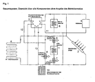
- Fig. 1 shows an example of the above-described system for seasonal use for solar cooling and for heating support using a latent heat storage 1.
- the drawing shows only the principle interconnection without specifying the exact plant engineering design.
- FIG. 2 to 7 the operation of the exemplary system in the various operating states is shown:
- Fig. Shows an overview of the various system components: latent heat storage 1, solar collector system 2, absorption heat pump or chiller 3, NT (low temperature) cooling / heating system 4, boiler 5, heat storage 6, air heat exchanger 7 to 9, Erdsondenstrom / storage or groundwater well 10th
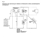
- Fig. 2 shows the system in cooling mode, ie preferably during the day.
- the solar collector system 2 supplies the drive heat to the drive side of the chiller 3 via a heating circuit 11.
- a heat store 6 can be integrated to even out this heat delivery between the solar collector system 2 and the chiller 3.
- the cold side of the chiller 3 is connected via a refrigeration circuit 12 to the NT (low temperature) cooling / heating system 4 and thus provides usable refrigeration for cooling the room.
- the waste heat side of the chiller 3 is connected via a cooling circuit 13 with the latent heat storage (PCM memory) 1.
- This latent heat storage stores the waste heat emitted by the refrigerator.
- a boiler 5 for the additional provision of drive heat as well as a geothermal or well system 10 for additional removal of waste heat of the chiller 3 can be used.
- FIGS. 2 to 4 show the operation of the system in the cooling mode, ie for the provision of cooling energy by solar thermal driven absorption chiller and time buffering of the waste heat of the chiller by means of latent heat storage (PCM memory).
- the recooling is supported in the illustrated variants in each case by a recooling, which can be used in different positions.
- a recooling instead of the recooling plant could also be a heat transfer to the ground by means of geothermal probes, ground collector or groundwater coupling.
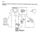
- the Figures 3 and 4 show how Fig. 2 the system in cooling mode, ie preferably during the day, but here with an additional air heat exchanger to support the removal of waste heat of the refrigerator 3 to the environment.
- the air heat exchanger 3 can be in series - see Fig. 3 - or parallel - see Fig. 4 - Are integrated to the latent heat storage 1 in the cooling circuit 13.
- serial Integration is advantageous in terms of operation of the refrigeration system 3 with the lowest possible recooling temperature, the coming of the chiller 3 cooling water first through the air heat exchanger 9 (see Fig. 1 ) lead and then through the latent heat storage. 1
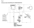
- Fig. 5 shows the re-cooling of the latent heat accumulator 1 in night mode.
- the re-cooling takes place via the air heat exchanger 7, which is connected via the return cooling circuit 13 of the refrigerator 3 with the latent heat storage.
- the wiring of the return cooling circuit 13 can be switched so that the chiller is no longer flowed through by cooling water (brine).
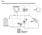
- Fig. 6 shows the solar heating operation with time buffering of the solar heat by means of latent heat storage 1:
- the solar collector system 2 is connected via the heating circuit with the NT (low temperature) cooling / heating system 4 and at the same time with the latent heat storage 1. Excess heat, which is not supplied via the heating circuit 14 to the NT (low temperature) cooling / heating system 4, takes up the latent heat storage 1.
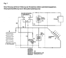
- Fig. 7 shows the solar heating mode with temporal buffering of the solar heat by means of latent heat storage, as in Fig. 6 shown, with additional use of a thermally driven heat pump 3 to support the heating operation.
- the Nutztudeabgabe the heat pump 3 via the opposite of the cold operation (see Fig. 2 ) Switched cooling circuit 13 to the heating circuit 14.
- the drive heat for the heat pump 3 is provided by means of boiler 5.
- As an environmental heat source for the heat pump 3 is an air heat exchanger 8 and / or a ground probe or groundwater well plant. These are over the opposite of the cold operation (see Fig. 2 ) switched refrigerant circuit 12 connected to the cold side of the refrigerator / heat pump 3.
Landscapes
- Engineering & Computer Science (AREA)
- Life Sciences & Earth Sciences (AREA)
- Mechanical Engineering (AREA)
- General Engineering & Computer Science (AREA)
- Sustainable Development (AREA)
- Chemical & Material Sciences (AREA)
- Combustion & Propulsion (AREA)
- Sustainable Energy (AREA)
- Physics & Mathematics (AREA)
- Thermal Sciences (AREA)
- Air Conditioning Control Device (AREA)
- Central Heating Systems (AREA)
Abstract
Description
Solarthermische Systeme werden dem Stand der Technik entsprechend vorwiegend eingesetzt, um Solarstrahlung in nutzbare Wärme für unterschiedliche Anwendungen - beispielsweise Brauchwassererwärmung, Gebäudeheizung oder industrielle Prozesse - zu verwandeln. Zur Wärmegewinnung finden unterschiedliche Arten von Solarkollektoren Verwendung. Zum Zweck des zeitlichen Ausgleich von Wärmeerzeugung und Wärmeverbrauch werden Wärmespeicher eingesetzt. Üblicherweise werden Warmwasserspeicher, gefüllt mit Heizkreiswasser oder Brauchwasser, eingesetzt. Dabei beruht der Speichereffekt auf der Speicherung sensibler Wärme, die zur Beladung bzw. Entladung des Speichers zu- bzw. abzuführen ist. Dies ist mit einer entsprechenden Temperaturänderung des Speichers verbunden.According to the state of the art, solar thermal systems are predominantly used to convert solar radiation into usable heat for different applications, for example domestic water heating, building heating or industrial processes. For heat recovery different types of solar collectors are used. For the purpose of the temporal balance of heat generation and heat consumption heat storage are used. Usually, hot water tanks filled with heating water or service water are used. In this case, the memory effect is based on the storage of sensible heat which is to be added or removed for the purpose of loading or unloading the store. This is associated with a corresponding temperature change of the memory.
Eine weiterer Anwendungsfall besteht in der Nutzung solarthermisch erzeugter Wärme zum Antrieb von thermisch angetriebenen Kälteanlagen - sogenannten Sorptionskälteanlagen. Gerade bei groß dimensionierten Solaranlagen, die über die Brauchwassererwärmung hinaus auch zur Unterstützung der Gebäudeheizung eingesetzt werden, werden außerhalb der Heizperiode große Wärmemengen verfügbar, die nicht zu Heizzwecken benötigt werden. Hier bietet sich der Einsatz von Sorptionskälteanlagen zur Bereitstellung von Klimakälte unter Ausnutzung der erzeugten Solarwärme an. Zur Bereitstellung von Antreibswärme für die Kälteerzeugung während Zeiten unzureichendem Solarwärmeertrags kann zusätzlich Antriebswärme mittels eines Heizkessels zur Verfügung gestellt werden.Another application is the use of solar thermal generated heat to drive thermally driven refrigeration systems - so-called sorption refrigeration systems. Especially in large-scale solar systems that are used in addition to the domestic water heating also to support the building heating, outside the heating period, large amounts of heat available that are not needed for heating purposes. Here, the use of sorption refrigeration systems for the provision of air conditioning using the generated solar heat offers. In order to provide driving heat for refrigeration during times of insufficient solar heat yield, motive heat can be additionally provided by means of a boiler.
Als Sorptionskälteanlagen können sowohl Anlagen mit flüssigem Sorptionsmittel - sogenannte Absorptionskälteanlagen - oder Anlagen mit festem Sorptionsmittel - sogenannte Adsorptionskälteanlagen - eingesetzt werden. In jedem Fall wird zur Erzeugung des gewünschten Kühleffekts - beispielsweise bereitgestellt mittels eines Kaltwasserkreislaufs mit Temperaturen im Bereich von etwa 5°C bis maximal etwa 18°C - Antriebswärme von wenigstens etwa 60°C benötigt. Die Funktion dieser Anlagen erfordert zwingend eine Abfuhr von Abwärme an die Umgebung bei einem mittleren Temperatumiveau von etwa 25 bis 40°C. Die anfallende Abwärmeleistung entspricht etwa der Summe der erzeugten Kälteleistung und der aufgenommenen Antriebswärmeleistung. Für die Abgabe dieser Abwärme an die Umgebung werden normalerweise Naßkühltürme in offener oder geschlossener Bauart, trockene Rückkühler oder Hybridkühltürme verwendet. Der Betrieb des Rückkühlwerkes ist in jedem Fall mit einem erheblichen Aufwand hinsichtlich Wasserverbrauch und Hilfsenergiebedarf für die Ventilation des Rückkühlwerk sowie für die Umwälzung des Kühlwasser verbunden, welches als Wärmeträger zwischen Kälteanlage und Rückkühlwerk dient. Eine Erhöhung des Temperaturniveaus der Abwärmeabgabe - beispielsweise bei heißen Umgebungstemperaturen - resultiert in einem Anstieg der für den Antrieb der Sorptionskälteanlage erforderlichen Antriebstemperatur. Dies ist wiederum mit einem Rückgang des Wirkungsgrades des Solarkollektors verbunden und führt so zu einer Einbuße an Solarwärmeleistung und folglich auch der verfügbaren Kälteleistung. In Systemen zur solaren Kühlung kommen oftmals Wärme- und / oder Kältespeicher zur zeitlichen Pufferung der solar erzeugten Antriebswärme bzw. der erzeugten Kälte zum Einsatz.As a sorption refrigeration systems both systems with liquid sorbent - so-called absorption refrigeration systems - or systems with solid sorbent - so-called adsorption refrigeration systems - can be used. In any event, to produce the desired cooling effect - for example, provided by means of a cold water circuit having temperatures ranging from about 5 ° C to a maximum of about 18 ° C - drive heat of at least about 60 ° C is needed. The function of these systems necessarily requires a dissipation of waste heat to the environment at a mean temperature level of about 25 to 40 ° C. The resulting waste heat output corresponds approximately to the sum of the generated cooling capacity and the absorbed drive thermal power. For the release of this waste heat to the environment will be normally used open or closed type wet cooling towers, dry recoolers or hybrid cooling towers. The operation of the recooling plant is connected in any case with a considerable effort in terms of water consumption and auxiliary energy demand for the ventilation of the recooling and for the circulation of the cooling water, which serves as a heat transfer between the refrigeration system and recooling. An increase in the temperature level of the waste heat output - for example, at hot ambient temperatures - results in an increase in the drive temperature required for driving the sorption refrigeration system. This in turn is associated with a decrease in the efficiency of the solar collector and thus leads to a loss of solar thermal power and consequently also the available cooling capacity. In systems for solar cooling often heat and / or cold storage for time buffering of the solar generated heat drive or the generated cold are used.
Aus der
Aus der
Es ist Aufgabe der vorliegenden Erfindung ein kombiniertes Kühl/Heiz-System anzugeben, dessen Wirkungsgrad durch wechselnde Umgebungsbedingungen weniger beeinflusst wird.It is an object of the present invention to provide a combined cooling / heating system whose efficiency is less affected by changing environmental conditions.
Die Lösung dieser Aufgabe erfolgt durch ein kombiniertes Kühl/Heiz-System gemäß Anspruch 1.The solution of this object is achieved by a combined cooling / heating system according to
Gegenstand der hier vorgelegten Erfindung ist die Verwendung eines Latentwärmespeichers (synonyme Bezeichnung: PCM-Speicher, engl.: phase change material für Phasenwechselmaterial) zur Aufnahme der von der Kälteanlage während des Kühlbetriebs abgegebenen Abwärme. Auf diese Weise kann ein definiertes niedriges Temperaturniveau für die Rückkühlung der Kälteanlage - unabhängig von der während des Betriebs der Kälteanlage herrschenden Umgebungstemperaturen - angeboten werden. Das Temperaturniveau der Rückkühlung wird durch die Umwandlungstemperatur des Latentwärmespeichers festgelegt. Bei dieser Temperatur findet ein Phasenwechsel des Speichermaterials statt. Der Speichereffekt beruht auf der Aufnahme bzw. Abgabe latenter Wärme während des Wechsels des Aggregatzustands. Auf diese Weise ist es sogar möglich, die Kälteanlage mit niedrigeren Rückkühltemperaturen als im Fall des Einsatzes eines konventionellen Rückkühlwerkes zu betreiben. Damit kann die Solarkollektortemperatur gesenkt werden, wodurch die Effizienz des Systems - d.h. der Kälteertrag pro Kollektorfläche der Solarkollektoranlage - steigt. Die Verwendung eines Latentwärmespeichers beinhaltet gegenüber der Speicherung sensibler Wärme den entscheidenden Vorteil, dass der Speicher während des gesamten Beladungsvorgangs annähernd bei konstanter Temperatur betrieben werden kann. Speicherung sensibler Wärme würde - unter der Annahme eines wirtschaftlich vertretbaren Volumens des Speichers - eine deutliche Erhöhung der Temperatur der Abwärmeabgabe der Kältemaschine mit zunehmender Beladung des Wärmespeichers bewirken. Dies würde zu einer deutlichen Einschränkung der Funktionsfähigkeit des Systems - in erster Linie zu einem Rückgang der zur Verfügung stehenden Kälteleistung - führen.The subject of the present invention is the use of a latent heat storage (synonymous designation: PCM memory, English: phase change material for phase change material) for receiving the votes of the refrigeration system during the cooling operation waste heat. In this way, a defined low temperature level for the recooling of the refrigeration system - regardless of the prevailing during operation of the refrigeration system ambient temperatures - are offered. The temperature level of the recooling is determined by the transformation temperature of the latent heat accumulator. At this temperature, a phase change of the storage material takes place. The storage effect is based on the absorption or release of latent heat during the change of state of aggregation. In this way it is even possible to operate the refrigeration system with lower recooling temperatures than in the case of the use of a conventional recooling plant. Thus, the solar collector temperature can be lowered, whereby the efficiency of the system - ie the cold yield per collector surface of the solar collector system - increases. The usage a latent heat storage compared to the storage of sensible heat has the decisive advantage that the memory during the entire loading process can be operated approximately at a constant temperature. Storage of sensible heat would - assuming an economically acceptable volume of the memory - cause a significant increase in the temperature of the waste heat output of the chiller with increasing loading of the heat storage. This would lead to a significant restriction of the functioning of the system - primarily to a reduction in the available cooling capacity.
Die vom Latentwärmespeicher während des Betriebs der Kälteanlage aufgenommene Wärme wird während der Nachtstunden über ein Rückkühlwerk an die Umgebung abgegeben. Auf diese Weise können die während der Nachstunden herrschenden niedrigeren Umgebungstemperaturen für die Abgabe der Abwärme der Kälteerzeugung an die Umgebung genutzt werden. Zudem wird verglichen mit der Beladungsdauer des Wärmespeichers während der Kälteerzeugung in der Regel ein längerer Zeitraum für die Entladung des Wärmespeichers zur Verfügung stehen, so dass die Entladung mit kleinerer Leistung und somit vergleichsweise geringer treibender Temperaturdifferenz erfolgen kann.The heat absorbed by the latent heat accumulator during operation of the refrigeration system is released into the environment via a recooling system during the night hours. In this way, the lower ambient temperatures prevailing during the hours of the night can be used for the release of the waste heat of the refrigeration to the environment. In addition, a longer period for the discharge of the heat accumulator will generally be available compared to the loading period of the heat accumulator during refrigeration, so that the discharge can be done with lower power and thus comparatively low driving temperature difference.
Zur Rückkühlung, d.h. als Wärmesenke für die Übertragung der Abwärme an die Umgebung, können die oben genannten Kühlturmarten oder eine Grundwasser-Brunnenanlage, ein Aquifer, ein Erdkollektor oder eine Erdsondenanlage eingesetzt werden. Im Fall der solaren Klimatisierung kann der Latentwärmespeicher zudem während der Nachtstunden sehr effizient durch Wärmeabgabe - vornehmlich mittels Wärmeabstrahlung - über die Solarkollektoranlage entladen werden. Insgesamt können verschiedene Wärmesenken gleichzeitig oder zeitlich versetzt zur Entladung des Wärmespeichers genutzt werden.For re-cooling, i. as a heat sink for the transfer of waste heat to the environment, the above-mentioned cooling tower types or a groundwater well, an aquifer, a ground collector or a geothermal probe can be used. In the case of solar air conditioning, the latent heat storage can also be discharged very efficiently through the solar collector system during the night hours by heat dissipation - primarily by means of heat radiation. Overall, different heat sinks can be used at the same time or offset in time for discharging the heat accumulator.
Das Rückkühlwerk kann während des Betriebs der Kälteanlage zur Unterstützung des Latentwärmespeichers eingesetzt werden; d.h. ein Teil der Abwärme der Kälteanlage kann sofort an die Umgebung abgeführt werden.The recooling system can be used during operation of the refrigeration system to support the latent heat storage; i.e. Part of the waste heat from the refrigeration system can be dissipated immediately to the environment.
In Systemen, bei denen solarthermische Wärme sowohl zum Antrieb einer Sorptionskälteanlage als auch zu Heizzwecken verwendet wird, kann der Latentwärmespeicher neben der oben beschriebenen Verwendung zur Rückkühlung der Kälteanlage auch zur Pufferung der solarthermisch erzeugten Heizwärme während der Heizperiode eingesetzt werden. Durch diese saisonal wechselnde Doppelnutzung ergibt sich ein besonders wirtschaftlicher Einsatz des Latentwärmespeichers.In systems where solar thermal heat is used both to drive a sorption refrigeration system and for heating purposes, the latent heat storage in addition to the above-described use for re-cooling the refrigeration system and for buffering the solar thermal heat produced be used during the heating season. This seasonally changing double use results in a particularly economical use of latent heat storage.
Entsprechend der Wahl der Umwandlungstemperatur des Phasenwechselmaterials zur Aufnahme der Abwärme der Kälteanlage bei Temperaturen um etwa 30°C eignet sich das hier beschriebene System in erster Linie für Niedertemperaturheizsysteme mit Heizkreistemperaturen unterhalb der gewählten Umwandlungstemperatur. Dies trifft vor allem auf Flächenheizsysteme, wie Wand- und Fußbodenheizungen, oder Installationen zur Betonkemaktivierung zu. Diese Systeme können während der Kühlperiode auch zur Kühlung des Verbrauchers - typischerweise eines Gebäudes - eingesetzt werden.According to the choice of the transition temperature of the phase change material to absorb the waste heat of the refrigeration system at temperatures of about 30 ° C, the system described here is primarily for low temperature heating systems with Heizkreistemperaturen below the selected transition temperature. This applies in particular to surface heating systems, such as wall and floor heating systems, or installations for concrete core activation. These systems can also be used during the cooling period to cool the consumer - typically a building.
Genauso wie bei der Rückkühlung der Kälteanlage hat auch im Heizbetrieb die Speicherung der Wärme auf einem definierten niedrigen Temperatumiveau - festgelegt durch die Umwandlungstemperatur des Latenwärmespeichermateriäls - einen positiven Effekt auf die Betriebsweise des Gesamtsystems. Durch die Speicherung der solarthermisch erzeugten Wärme bei niedriger Speichertemperatur kann das Solarkollektorsystem unabhängig vom Ladezustand des Speichers immer mit niedriger Wärmeträgertemperatur von maximal etwa 40°C betrieben werden. Dadurch kann das Kollektorsystem mit deutlich höherem Wirkungsgrad im vergleich zum Betrieb mit höherer Betriebstemperatur von normalerweise etwa 60 bis 80°C betrieben werden.Just as with the recooling of the refrigeration system, the storage of heat at a defined low temperature level - determined by the transformation temperature of the latent heat storage material - also has a positive effect on the operating mode of the entire system in heating mode. By storing the solar thermal heat generated at low storage temperature, the solar collector system can always be operated with a low heat carrier temperature of about 40 ° C regardless of the state of charge of the memory. As a result, the collector system can be operated with significantly higher efficiency compared to operating at a higher operating temperature of normally about 60 to 80 ° C.
Neben der Einspeisung von Niedertemperatursolarwärme in das Heizungssystem kann zusätzlich auch Wärme aus einem Heizkessel in das Helzungssystem eingespeist werden.In addition to feeding low-temperature solar heat into the heating system, heat from a boiler can also be fed into the heating system.
Im Solar-Heizbetrieb - d.h. wenn der Latentwärmespeicher zur zeitlichen Pufferung der solarthermisch erzeugten Wärme eingesetzt wird - kann zusätzlich die während der Kühlperiode eingesetzte Kälteanlage als Wärmepumpe zur Bereitstellung von Niedertemperaturheizwärme eingesetzt werden. Das während der Kühlperiode eingesetzte Rückkühlwerk oder andere Systeme können hierzu zur Gewinnung von Umgebungswärme, die mittels Wärmepumpe auf Heiztemperatumiveau angehoben wird, eingesetzt werden. Hierfür eignen sich neben den verschiedenen Kühlturmarten vor allem Grundwasser-Brunnenanlagen, Erdsonden, Erdkollektoren und Luft-Sole-Wärmetauscher.In solar heating mode - ie when the latent heat storage is used for temporal buffering of solar thermal heat generated - additionally used during the cooling period refrigeration system can be used as a heat pump to provide low-temperature heating. The recooling plant or other systems used during the cooling period can be used for this purpose to obtain ambient heat, which is raised by the heat pump to heating temperature level. In addition to the various types of cooling tower, groundwater wells, geothermal probes, ground collectors and air-brine heat exchangers are particularly suitable for this purpose.
Neben der hier beschriebenen Konstellation eines Systems mit Sorptionskälteanlage ist die Erfindung ebenso anwendbar für Systeme mit mechanischer Kälteerzeugung; d.h. Kompressionskältemaschine. Auch in diesem Fall kann der Latentwärmespeicher sowohl zur Aufnahme der Abwärme der Kälteanlage und zeitversetzter Abgabe der Abwärme an die Umgebung als auch zur Pufferung von Niedertemperaturheizwärme für den Heizbetrieb eingesetzt werden. Auch hier ist im saisonalen oder tageszeitlichen Wechsel die Verwendung der Kälteanlage als Wärmepumpe zur Bereitstellung von Heizwärme möglich.In addition to the constellation of a sorption refrigeration system described herein, the invention is equally applicable to systems with mechanical refrigeration; i.e. Compression chiller. Also in this case, the latent heat storage can be used both for receiving the waste heat of the refrigeration system and time-delayed release of waste heat to the environment as well as for buffering Niedertemperaturheizwärme for heating operation. Again, the use of the refrigeration system as a heat pump to provide heating heat is possible in seasonal or daily time change.
Die übrigen Unteransprüche beziehen sich auf weitere vorteilhafte Ausgestaltungen der Erfindung.The remaining subclaims relate to further advantageous embodiments of the invention.
Weitere Einzelheiten, Merkmale und Vorteile der Erfindung ergeben sich aus der nachfolgenden Beschreibung bevorzugter Ausführungsformen anhand der Zeichnung. Es zeigt
- Fig. 1
- eine schematische Darstellung einer beispielhaften Ausführungsform der Erfindung,
- Fig. 2
- den Kühlbetrieb (Tagbetrieb) der beispielhaften Ausführungsform, während dem die Abwärme der Kältemaschine mittels Latentwärmespeicher (PCM- Speicher) zwischengespeichert wird,
- Fig. 3
- den Kühlbetrieb (Tagbetrieb) der beispielhaften Ausführungsform, während dem seriell zum Latentwärmespeicher ein Rückkühler eingesetzt wird,
- Fig. 4
- den Kühlbetrieb (Tagbetrieb) der beispielhaften Ausführungsform, während dem parallel zum Latentwärmespeicher ein Rückkühler eingesetzt wird,
- Fig. 5.
- den Kühlbetriebes (Nachtbetrieb) der beispielhaften Ausführungsform, während der Latentwärmespeicher durch den Rückkühler entladen wird,
- Fig. 6
- den Solar-Heizbetrieb, bei dem die solar erzeugte Heizwärme zeitlich mittels Latentwärmespeicher gepuffert wird, und
- Fig. 7
- den Solar-Heizbetrieb, bei dem die solar erzeugte Heizwärme zeitlich mittels Latentwärmespeicher gepuffert wird und zusätzlich der Heizbetrieb durch eine Absorptionswärmepumpe unterstützt wird.
- Fig. 1
- a schematic representation of an exemplary embodiment of the invention,
- Fig. 2
- the cooling operation (daytime operation) of the exemplary embodiment, during which the waste heat of the chiller is temporarily stored by means of latent heat storage (PCM memory),
- Fig. 3
- the cooling operation (day mode) of the exemplary embodiment, during which a recooler is used in series with the latent heat accumulator,
- Fig. 4
- the cooling operation (day mode) of the exemplary embodiment, during which a recooler is used in parallel to the latent heat storage,
- Fig. 5.
- the cooling operation (night mode) of the exemplary embodiment, while the latent heat storage is discharged by the recooler,
- Fig. 6
- the solar heating mode, in which the solar generated heating heat is buffered by means of latent heat storage, and
- Fig. 7
- the solar heating mode, in which the solar generated heating heat is buffered in time by means of latent heat storage and in addition the heating operation is supported by an absorption heat pump.
Fig. gibt einen Überblick über die verschiedenen Anlagenkomponenten: Latentwärmespeicher 1, Solarkollektoranlage 2, Absorptionswärmepumpe bzw. Kältemaschine 3, NT(Niedertemperatur)-Kühl-/Heizsystem 4, Heizkessel 5, Wärmespeicher 6, Luftwärmetauscher 7 bis 9, Erdsondenanlage/-speicher oder Grundwasserbrunnen 10.Fig. Shows an overview of the various system components:
Die
Die
Claims (13)
- A combined cooling/heating system having- a cooling unit (3) having a cold area, which provides useful refrigeration to a low temperature level, and a lost heat area, which emits lost heat to a middle temperature level,- a latent heat storage device (1) for temporary storage of the lost heat from the cooling unit (3) in cooling mode,- an ambient heat exchanger device or re-cooling facility (7, 8, 9, 10) for emitting the lost heat from the latent heat storage device (1) and/or from the lost heat area of the cooling unit (3) to the surroundings in cooling mode,- a thermal heat source (2, 5) for feeding heat into the latent heat storage device (1) in heating mode,- at least one device (4) for transferring the useful refrigeration/thermal heat to a load that can be connected to the latent heat storage device (1) and the cold area of the cooling unit (3), and- a control device for switching between cooling and heating mode,wherein, in cooling mode,
on the one hand the cold area of the cooling unit (3) is connected to the at least one device (4) for transferring useful refrigeration/thermal heat to a load in order to provide useful refrigeration, and the latent heat storage device (1) is connected to the lost heat area of the cooling unit (3) in order to store lost heat from the cooling unit (3) temporarily in the latent heat storage device (1), and on the other hand the latent heat storage device (1) is connected to the re-cooling facility (7, 8, 9, 10) in order to emit the lost heat temporarily stored in the latent heat storage device (1) via the re-cooling facility (7, 8, 9, 10) to the surroundings with a time delay,
and wherein, in heating mode,
via the heat source (2, 5) thermal heat is fed in and stored in the latent heat storage device (1) and the latent heat storage device (1) is connected to the device (4) for transferring useful refrigeration/thermal heat to a load in order to emit the thermal heat stored temporarily in the latent heat storage device (1) to the at least one device (4) for transferring useful refrigeration/thermal heat to a load. - A system according to claim 1, characterised in that the thermal heat source (2, 5) can be connected in heating mode directly to the at least one device (4) for transferring useful refrigeration/thermal heat to a load.
- A system according to any one of the preceding claims, characterised in that the thermal heat source (2, 5) comprises a solar collector system (2) and/or a boiler (5) and/or a combined heat and power facility and/or a cooling unit/heat pump (3).
- A system according to any one of the preceding claims, characterised in that the cooling unit (3) is a sorption cooling unit.
- A system according to any one of the preceding claims, characterised in that the cooling unit (3) is driven at least partly by means of heat from the thermal heat source (2,5).
- A system according to any one of the preceding claims 4 and 5, characterised in that the sorption cooling unit (3) is of two-stage construction and comprises an upper and a lower circulation stage,
in that a fossil heat source is provided to drive the upper circulation stage, and
in that the lower circulation stage is heated by means of hot water from the thermal heat source (2, 5). - A system according to any one of the preceding claims, characterised in that in cooling mode the ambient heat exchanger device (7, 8, 9, 10) is connected to the latent heat storage device (1) and to the lost heat area of the cooling unit (3).
- A system according to claim 7, characterised in that the heat that can be emitted per unit of time from the ambient heat exchanger device (7, 8, 9, 10) to the surroundings is greater than the heat accumulating per unit of time in the lost heat area of the cooling unit (3), so that the amount of heat stored temporarily in the latent heat storage device (1) decreases.
- A system according to claim 7, characterised in that the heat that can be emitted per unit of time from the ambient heat exchanger device (7, 8, 9, 10) to the surroundings is less than the heat accumulating per unit of time in the lost heat area of the cooling unit, so that the amount of heat stored temporarily in the latent heat storage device (1) increases.
- A system according to any one of the preceding claims, characterised in that in heating mode the cooling unit (3) is connected as a heat pump, wherein the cold area takes up ambient heat and the lost heat area is used a thermal heat source.
- A system according to claim 10, characterised in that in heating mode the ambient heat exchanger device (7, 8, 9, 10) can be connected to the cold area of the heat pump (3) in order to provide ambient heat for the cold area of the heat pump (3).
- A system according to any one of the preceding claims 10 to 11, characterised in that the heat pump (3) is driven by means of a boiler (5).
- A system according to any one of the preceding claims 10 to 11, characterised in that the heat pump (3) is driven by means of direct heating.
Applications Claiming Priority (2)
| Application Number | Priority Date | Filing Date | Title |
|---|---|---|---|
| DE102005013012A DE102005013012A1 (en) | 2005-03-21 | 2005-03-21 | Latent heat storage for efficient cooling and heating systems |
| PCT/EP2006/002606 WO2006100047A2 (en) | 2005-03-21 | 2006-03-21 | Latent heat storage for efficient cooling and heating systems |
Publications (2)
| Publication Number | Publication Date |
|---|---|
| EP1861663A2 EP1861663A2 (en) | 2007-12-05 |
| EP1861663B1 true EP1861663B1 (en) | 2011-08-24 |
Family
ID=36499038
Family Applications (1)
| Application Number | Title | Priority Date | Filing Date |
|---|---|---|---|
| EP06723606A Expired - Lifetime EP1861663B1 (en) | 2005-03-21 | 2006-03-21 | Latent heat storage for efficient cooling and heating systems |
Country Status (5)
| Country | Link |
|---|---|
| EP (1) | EP1861663B1 (en) |
| AT (1) | ATE521861T1 (en) |
| DE (1) | DE102005013012A1 (en) |
| ES (1) | ES2372066T3 (en) |
| WO (1) | WO2006100047A2 (en) |
Cited By (1)
| Publication number | Priority date | Publication date | Assignee | Title |
|---|---|---|---|---|
| US12241457B1 (en) * | 2022-08-24 | 2025-03-04 | Mark H. Taylor | Renewable geothermal energy harvesting systems and methods |
Families Citing this family (26)
| Publication number | Priority date | Publication date | Assignee | Title |
|---|---|---|---|---|
| DE102008031163A1 (en) | 2008-07-03 | 2010-01-07 | Bayerisches Zentrum für Angewandte Energieforschung e.V. | Hollow fibres filled with latent heat storage material, i.e. phase change material, used for thermal insulation, e.g. in building components or in the form of woven fabric for clothing |
| GB2463704A (en) * | 2008-09-23 | 2010-03-24 | Solar Polar Ltd | Solar-powered absorption refrigeration system with phase-change heat store |
| GB2463705A (en) | 2008-09-23 | 2010-03-24 | Solar Polar Ltd | Solar-powered modular absorption refrigeration system |
| AU2010212610A1 (en) * | 2009-02-11 | 2011-09-08 | Vkr Holding A/S | Fluid conditioning arrangements |
| CN102395833A (en) * | 2009-02-11 | 2012-03-28 | 阿蒂卡科技有限公司 | Fluid conditioning arrangements |
| GB2470619A (en) * | 2009-02-11 | 2010-12-01 | Artica Technologies Ltd | Phase change material compound and pack |
| IT1393132B1 (en) * | 2009-03-09 | 2012-04-11 | Eubios S P A | PLANT FOR THERMO-ADJUSTMENT OF A FIRST AND SECOND FLUID FOR AIR-CONDITIONING |
| EP2567155A2 (en) * | 2010-05-07 | 2013-03-13 | Kalús, Daniel | The combined constructional-energetic system for buildings |
| DE102010019964B4 (en) * | 2010-05-08 | 2015-07-02 | Raenergie Gmbh & Co. Kg | Method and device for converting and storing thermal energies |
| CN101922753B (en) * | 2010-08-27 | 2012-07-25 | 清华大学 | Solar energy and geothermal energy assistant centralized heating system |
| DE102011007626B4 (en) * | 2011-04-18 | 2013-05-29 | Sgl Carbon Se | Latent heat storage device and operating method for a latent heat storage device |
| EP2766668B1 (en) | 2011-10-13 | 2017-11-15 | Carrier Corporation | Thermal energy storage in a chiller system |
| FR2982661A1 (en) * | 2011-11-10 | 2013-05-17 | Cythelia Expertise Et Conseil Soc De Conseils Et D Etudes En En Solaire | INSTALLATION FOR TEMPERATURE CONTROL AND HOT WATER PRODUCTION AND METHOD FOR IMPLEMENTING SUCH INSTALLATION |
| DE102012206296A1 (en) * | 2012-04-17 | 2013-10-17 | Siemens Aktiengesellschaft | Plant for storage and delivery of thermal energy and method of operation thereof |
| DE102012112646A1 (en) * | 2012-12-19 | 2014-06-26 | Rittal Gmbh & Co. Kg | Cooling arrangement for use as switch cabinet-cooling device or as free cooler for cooling computer centers or office buildings, has heat exchanger that stays in heat conductive contact with phase change material held in heat accumulator |
| EP2857640A1 (en) * | 2013-10-01 | 2015-04-08 | Astrium GmbH | Device having at least one latent heat storage unit |
| DE102014206415A1 (en) | 2014-04-03 | 2015-10-08 | Fraunhofer-Gesellschaft zur Förderung der angewandten Forschung e.V. | Heat storage arrangement and method for operating such |
| CN104566722B (en) * | 2014-12-31 | 2017-06-13 | 山东一村空调有限公司 | A kind of natural energy air regulator cyclic softening Groundwater air-conditioning |
| CN104456799B (en) * | 2014-12-31 | 2017-03-22 | 山东一村空调有限公司 | Solar auxiliary heating wind window circulating water air conditioner |
| CN104566721B (en) * | 2014-12-31 | 2018-08-21 | 山东一村空调有限公司 | A kind of natural energy air regulator circulating water air conditioner |
| ES2664731T3 (en) | 2015-02-09 | 2020-01-30 | Egpt Ltd | Efficiency improvement in power plants |
| CN104864460B (en) * | 2015-04-29 | 2017-10-17 | 大连理工大学 | Rural active solar thermal storage ground system |
| CN104913364B (en) * | 2015-06-04 | 2017-11-17 | 北京建筑大学 | A kind of solar energy soil source hot water type absorption heat pump heating system |
| CN111765509B (en) * | 2020-07-01 | 2021-02-26 | 河北工业大学 | A distributed wind-solar hybrid two-way supply energy station |
| DE102021122516A1 (en) * | 2021-08-31 | 2023-03-02 | Viessmann Climate Solutions Se | METHOD OF OPERATING AN ENERGY SUPPLY SYSTEM AND ENERGY SUPPLY SYSTEM FOR PROVIDING COOLING POWER AND/OR HEATING POWER |
| FR3151898B1 (en) * | 2023-07-31 | 2026-01-02 | Sun Ice Energy Pte Ltd | THERMAL ENERGY STORAGE SYSTEM COMPRISING A PHASE CHANGE MATERIAL AND A THERMAL CONDITIONING LOOP COMPRISING SUCH A SYSTEM |
Family Cites Families (5)
| Publication number | Priority date | Publication date | Assignee | Title |
|---|---|---|---|---|
| US4169554A (en) * | 1977-10-20 | 1979-10-02 | Camp Eldon D | Solar energy system with heat pump assistance |
| US4205529A (en) * | 1978-12-04 | 1980-06-03 | The United States Of America As Represented By The United States Department Of Energy | LiCl Dehumidifier LiBr absorption chiller hybrid air conditioning system with energy recovery |
| JPS5845468A (en) * | 1981-09-11 | 1983-03-16 | 株式会社日立製作所 | Absorption refrigeration equipment |
| US5497629A (en) * | 1993-03-23 | 1996-03-12 | Store Heat And Produce Energy, Inc. | Heating and cooling systems incorporating thermal storage |
| US5355688A (en) * | 1993-03-23 | 1994-10-18 | Shape, Inc. | Heat pump and air conditioning system incorporating thermal storage |
-
2005
- 2005-03-21 DE DE102005013012A patent/DE102005013012A1/en not_active Withdrawn
-
2006
- 2006-03-21 ES ES06723606T patent/ES2372066T3/en not_active Expired - Lifetime
- 2006-03-21 WO PCT/EP2006/002606 patent/WO2006100047A2/en not_active Ceased
- 2006-03-21 AT AT06723606T patent/ATE521861T1/en active
- 2006-03-21 EP EP06723606A patent/EP1861663B1/en not_active Expired - Lifetime
Cited By (1)
| Publication number | Priority date | Publication date | Assignee | Title |
|---|---|---|---|---|
| US12241457B1 (en) * | 2022-08-24 | 2025-03-04 | Mark H. Taylor | Renewable geothermal energy harvesting systems and methods |
Also Published As
| Publication number | Publication date |
|---|---|
| WO2006100047A2 (en) | 2006-09-28 |
| ES2372066T3 (en) | 2012-01-13 |
| ATE521861T1 (en) | 2011-09-15 |
| EP1861663A2 (en) | 2007-12-05 |
| WO2006100047A3 (en) | 2007-10-04 |
| DE102005013012A1 (en) | 2006-09-28 |
Similar Documents
| Publication | Publication Date | Title |
|---|---|---|
| EP1861663B1 (en) | Latent heat storage for efficient cooling and heating systems | |
| Helm et al. | Solar heating and cooling system with absorption chiller and low temperature latent heat storage: Energetic performance and operational experience | |
| DE10300427B4 (en) | Solar system with heat pump | |
| James et al. | Thermal analysis of heat pump systems using photovoltaic-thermal collectors: a review: A. James et al. | |
| KR101761176B1 (en) | Energy Storage System | |
| DE2807075C2 (en) | Process for operating a thermal power station and a suitable thermal power station | |
| EP2694885B1 (en) | Device and method for converting solar radiation energy to electrical power and/or to heat | |
| DE102008040028A1 (en) | Energy conversion system for supplying e.g. electrical energy, to e.g. consumer in residential building, has Peltier converter receiving electrical energy from battery and/or another Peltier converter and delivering heat energy to consumer | |
| EP2331880A2 (en) | Method and device for providing usable heat energy | |
| DE102008008652A1 (en) | Thermal electrical accumulator for use in solar thermal plants for wash water heating and heating backup, comprises heat reservoir and cold reservoir, which are thermally separated, and arrangement of thermoelectric generators are provided | |
| WO2007134825A2 (en) | Arrangement and method for obtaining energy from solar radiation | |
| WO2010136381A2 (en) | Device and method for cooling solar cells by means of a flowing cooling medium | |
| DE102017006550A1 (en) | HVACC system for heating, ventilation, air conditioning and central refrigerant supply for a building | |
| EP2764298B1 (en) | Cogeneration plant and operation method therefor | |
| DE102005032764A1 (en) | Collector for energy from all sources on a regenerative basis uses photovoltaic recombination heat and solar excess heat with heat pump and thermo-electric conversion | |
| DE19927027C1 (en) | Heat production arrangement from environmental energies, having solar collector, heat swapper, heat pump, and fluid storages which are connected selectively to assure energetically most favorable arrangement | |
| DE2417220A1 (en) | Heating unit combined with air conditioning - using natural energy sources and off peak current in combination | |
| EP2247898B1 (en) | Method for optimizing thermal energy current guidance | |
| DE102012104996A1 (en) | Energy concept system used for supplying power to e.g. refrigerator in building, has heat pump which distributes thermal energy to photovoltaic module through solar thermal collector | |
| DE2509965B2 (en) | Process for space heating by means of a heat pump cycle | |
| JP4385447B2 (en) | Thermal storage air conditioner | |
| DE202015102294U1 (en) | Solar and convector system roof | |
| DE202014003951U1 (en) | Energy supply device for heat pumps and / or air conditioners | |
| DE10024044A1 (en) | Heat pump or refrigeration system has direct wind power drive for heating and cooling without external energy, rotor mast acting as evaporator with heat exchanger lamellas | |
| DE102014013614A1 (en) | Solar heating with photovoltaic-thermal collector |
Legal Events
| Date | Code | Title | Description |
|---|---|---|---|
| PUAI | Public reference made under article 153(3) epc to a published international application that has entered the european phase |
Free format text: ORIGINAL CODE: 0009012 |
|
| 17P | Request for examination filed |
Effective date: 20071002 |
|
| AK | Designated contracting states |
Kind code of ref document: A2 Designated state(s): AT BE BG CH CY CZ DE DK EE ES FI FR GB GR HU IE IS IT LI LT LU LV MC NL PL PT RO SE SI SK TR |
|
| AX | Request for extension of the european patent |
Extension state: AL BA HR MK YU |
|
| DAX | Request for extension of the european patent (deleted) | ||
| 17Q | First examination report despatched |
Effective date: 20090130 |
|
| GRAP | Despatch of communication of intention to grant a patent |
Free format text: ORIGINAL CODE: EPIDOSNIGR1 |
|
| GRAS | Grant fee paid |
Free format text: ORIGINAL CODE: EPIDOSNIGR3 |
|
| GRAA | (expected) grant |
Free format text: ORIGINAL CODE: 0009210 |
|
| AK | Designated contracting states |
Kind code of ref document: B1 Designated state(s): AT BE BG CH CY CZ DE DK EE ES FI FR GB GR HU IE IS IT LI LT LU LV MC NL PL PT RO SE SI SK TR |
|
| REG | Reference to a national code |
Ref country code: GB Ref legal event code: FG4D Free format text: NOT ENGLISH |
|
| REG | Reference to a national code |
Ref country code: CH Ref legal event code: EP |
|
| REG | Reference to a national code |
Ref country code: IE Ref legal event code: FG4D Free format text: LANGUAGE OF EP DOCUMENT: GERMAN |
|
| REG | Reference to a national code |
Ref country code: DE Ref legal event code: R096 Ref document number: 502006010071 Country of ref document: DE Effective date: 20111110 |
|
| REG | Reference to a national code |
Ref country code: NL Ref legal event code: VDEP Effective date: 20110824 |
|
| REG | Reference to a national code |
Ref country code: ES Ref legal event code: FG2A Ref document number: 2372066 Country of ref document: ES Kind code of ref document: T3 Effective date: 20120113 |
|
| LTIE | Lt: invalidation of european patent or patent extension |
Effective date: 20110824 |
|
| PG25 | Lapsed in a contracting state [announced via postgrant information from national office to epo] |
Ref country code: LT Free format text: LAPSE BECAUSE OF FAILURE TO SUBMIT A TRANSLATION OF THE DESCRIPTION OR TO PAY THE FEE WITHIN THE PRESCRIBED TIME-LIMIT Effective date: 20110824 Ref country code: NL Free format text: LAPSE BECAUSE OF FAILURE TO SUBMIT A TRANSLATION OF THE DESCRIPTION OR TO PAY THE FEE WITHIN THE PRESCRIBED TIME-LIMIT Effective date: 20110824 Ref country code: IS Free format text: LAPSE BECAUSE OF FAILURE TO SUBMIT A TRANSLATION OF THE DESCRIPTION OR TO PAY THE FEE WITHIN THE PRESCRIBED TIME-LIMIT Effective date: 20111224 Ref country code: FI Free format text: LAPSE BECAUSE OF FAILURE TO SUBMIT A TRANSLATION OF THE DESCRIPTION OR TO PAY THE FEE WITHIN THE PRESCRIBED TIME-LIMIT Effective date: 20110824 Ref country code: SE Free format text: LAPSE BECAUSE OF FAILURE TO SUBMIT A TRANSLATION OF THE DESCRIPTION OR TO PAY THE FEE WITHIN THE PRESCRIBED TIME-LIMIT Effective date: 20110824 Ref country code: PT Free format text: LAPSE BECAUSE OF FAILURE TO SUBMIT A TRANSLATION OF THE DESCRIPTION OR TO PAY THE FEE WITHIN THE PRESCRIBED TIME-LIMIT Effective date: 20111226 |
|
| PG25 | Lapsed in a contracting state [announced via postgrant information from national office to epo] |
Ref country code: SI Free format text: LAPSE BECAUSE OF FAILURE TO SUBMIT A TRANSLATION OF THE DESCRIPTION OR TO PAY THE FEE WITHIN THE PRESCRIBED TIME-LIMIT Effective date: 20110824 Ref country code: LV Free format text: LAPSE BECAUSE OF FAILURE TO SUBMIT A TRANSLATION OF THE DESCRIPTION OR TO PAY THE FEE WITHIN THE PRESCRIBED TIME-LIMIT Effective date: 20110824 Ref country code: CY Free format text: LAPSE BECAUSE OF FAILURE TO SUBMIT A TRANSLATION OF THE DESCRIPTION OR TO PAY THE FEE WITHIN THE PRESCRIBED TIME-LIMIT Effective date: 20110824 Ref country code: PL Free format text: LAPSE BECAUSE OF FAILURE TO SUBMIT A TRANSLATION OF THE DESCRIPTION OR TO PAY THE FEE WITHIN THE PRESCRIBED TIME-LIMIT Effective date: 20110824 Ref country code: GR Free format text: LAPSE BECAUSE OF FAILURE TO SUBMIT A TRANSLATION OF THE DESCRIPTION OR TO PAY THE FEE WITHIN THE PRESCRIBED TIME-LIMIT Effective date: 20111125 |
|
| REG | Reference to a national code |
Ref country code: IE Ref legal event code: FD4D |
|
| PG25 | Lapsed in a contracting state [announced via postgrant information from national office to epo] |
Ref country code: SK Free format text: LAPSE BECAUSE OF FAILURE TO SUBMIT A TRANSLATION OF THE DESCRIPTION OR TO PAY THE FEE WITHIN THE PRESCRIBED TIME-LIMIT Effective date: 20110824 Ref country code: CZ Free format text: LAPSE BECAUSE OF FAILURE TO SUBMIT A TRANSLATION OF THE DESCRIPTION OR TO PAY THE FEE WITHIN THE PRESCRIBED TIME-LIMIT Effective date: 20110824 Ref country code: IE Free format text: LAPSE BECAUSE OF FAILURE TO SUBMIT A TRANSLATION OF THE DESCRIPTION OR TO PAY THE FEE WITHIN THE PRESCRIBED TIME-LIMIT Effective date: 20110824 |
|
| PG25 | Lapsed in a contracting state [announced via postgrant information from national office to epo] |
Ref country code: RO Free format text: LAPSE BECAUSE OF FAILURE TO SUBMIT A TRANSLATION OF THE DESCRIPTION OR TO PAY THE FEE WITHIN THE PRESCRIBED TIME-LIMIT Effective date: 20110824 Ref country code: EE Free format text: LAPSE BECAUSE OF FAILURE TO SUBMIT A TRANSLATION OF THE DESCRIPTION OR TO PAY THE FEE WITHIN THE PRESCRIBED TIME-LIMIT Effective date: 20110824 |
|
| PG25 | Lapsed in a contracting state [announced via postgrant information from national office to epo] |
Ref country code: DK Free format text: LAPSE BECAUSE OF FAILURE TO SUBMIT A TRANSLATION OF THE DESCRIPTION OR TO PAY THE FEE WITHIN THE PRESCRIBED TIME-LIMIT Effective date: 20110824 |
|
| PLBE | No opposition filed within time limit |
Free format text: ORIGINAL CODE: 0009261 |
|
| STAA | Information on the status of an ep patent application or granted ep patent |
Free format text: STATUS: NO OPPOSITION FILED WITHIN TIME LIMIT |
|
| 26N | No opposition filed |
Effective date: 20120525 |
|
| REG | Reference to a national code |
Ref country code: DE Ref legal event code: R097 Ref document number: 502006010071 Country of ref document: DE Effective date: 20120525 |
|
| BERE | Be: lapsed |
Owner name: ZAE BAYERN BAYERISCHES ZENTRUM FUR ANGEWANDTE ENE Effective date: 20120331 |
|
| PG25 | Lapsed in a contracting state [announced via postgrant information from national office to epo] |
Ref country code: MC Free format text: LAPSE BECAUSE OF NON-PAYMENT OF DUE FEES Effective date: 20120331 |
|
| REG | Reference to a national code |
Ref country code: CH Ref legal event code: PL |
|
| PG25 | Lapsed in a contracting state [announced via postgrant information from national office to epo] |
Ref country code: CH Free format text: LAPSE BECAUSE OF NON-PAYMENT OF DUE FEES Effective date: 20120331 Ref country code: LI Free format text: LAPSE BECAUSE OF NON-PAYMENT OF DUE FEES Effective date: 20120331 Ref country code: BE Free format text: LAPSE BECAUSE OF NON-PAYMENT OF DUE FEES Effective date: 20120331 |
|
| REG | Reference to a national code |
Ref country code: AT Ref legal event code: MM01 Ref document number: 521861 Country of ref document: AT Kind code of ref document: T Effective date: 20120321 |
|
| PG25 | Lapsed in a contracting state [announced via postgrant information from national office to epo] |
Ref country code: BG Free format text: LAPSE BECAUSE OF FAILURE TO SUBMIT A TRANSLATION OF THE DESCRIPTION OR TO PAY THE FEE WITHIN THE PRESCRIBED TIME-LIMIT Effective date: 20111124 |
|
| PG25 | Lapsed in a contracting state [announced via postgrant information from national office to epo] |
Ref country code: AT Free format text: LAPSE BECAUSE OF NON-PAYMENT OF DUE FEES Effective date: 20120321 |
|
| PG25 | Lapsed in a contracting state [announced via postgrant information from national office to epo] |
Ref country code: TR Free format text: LAPSE BECAUSE OF FAILURE TO SUBMIT A TRANSLATION OF THE DESCRIPTION OR TO PAY THE FEE WITHIN THE PRESCRIBED TIME-LIMIT Effective date: 20110824 |
|
| PG25 | Lapsed in a contracting state [announced via postgrant information from national office to epo] |
Ref country code: LU Free format text: LAPSE BECAUSE OF NON-PAYMENT OF DUE FEES Effective date: 20120321 |
|
| PG25 | Lapsed in a contracting state [announced via postgrant information from national office to epo] |
Ref country code: HU Free format text: LAPSE BECAUSE OF FAILURE TO SUBMIT A TRANSLATION OF THE DESCRIPTION OR TO PAY THE FEE WITHIN THE PRESCRIBED TIME-LIMIT Effective date: 20060321 |
|
| REG | Reference to a national code |
Ref country code: FR Ref legal event code: PLFP Year of fee payment: 11 |
|
| REG | Reference to a national code |
Ref country code: FR Ref legal event code: PLFP Year of fee payment: 12 |
|
| REG | Reference to a national code |
Ref country code: FR Ref legal event code: PLFP Year of fee payment: 13 |
|
| PGFP | Annual fee paid to national office [announced via postgrant information from national office to epo] |
Ref country code: IT Payment date: 20200325 Year of fee payment: 15 Ref country code: DE Payment date: 20200302 Year of fee payment: 15 Ref country code: GB Payment date: 20200325 Year of fee payment: 15 |
|
| PGFP | Annual fee paid to national office [announced via postgrant information from national office to epo] |
Ref country code: FR Payment date: 20200324 Year of fee payment: 15 |
|
| PGFP | Annual fee paid to national office [announced via postgrant information from national office to epo] |
Ref country code: ES Payment date: 20200421 Year of fee payment: 15 |
|
| REG | Reference to a national code |
Ref country code: DE Ref legal event code: R119 Ref document number: 502006010071 Country of ref document: DE |
|
| GBPC | Gb: european patent ceased through non-payment of renewal fee |
Effective date: 20210321 |
|
| PG25 | Lapsed in a contracting state [announced via postgrant information from national office to epo] |
Ref country code: GB Free format text: LAPSE BECAUSE OF NON-PAYMENT OF DUE FEES Effective date: 20210321 Ref country code: FR Free format text: LAPSE BECAUSE OF NON-PAYMENT OF DUE FEES Effective date: 20210331 Ref country code: DE Free format text: LAPSE BECAUSE OF NON-PAYMENT OF DUE FEES Effective date: 20211001 |
|
| PG25 | Lapsed in a contracting state [announced via postgrant information from national office to epo] |
Ref country code: IT Free format text: LAPSE BECAUSE OF NON-PAYMENT OF DUE FEES Effective date: 20210321 |
|
| REG | Reference to a national code |
Ref country code: ES Ref legal event code: FD2A Effective date: 20220523 |
|
| PG25 | Lapsed in a contracting state [announced via postgrant information from national office to epo] |
Ref country code: ES Free format text: LAPSE BECAUSE OF NON-PAYMENT OF DUE FEES Effective date: 20210322 |