EP1861663B1 - Accumulateur de chaleur latente pour systemes de refroidissement et de chauffage performants - Google Patents
Accumulateur de chaleur latente pour systemes de refroidissement et de chauffage performants Download PDFInfo
- Publication number
- EP1861663B1 EP1861663B1 EP06723606A EP06723606A EP1861663B1 EP 1861663 B1 EP1861663 B1 EP 1861663B1 EP 06723606 A EP06723606 A EP 06723606A EP 06723606 A EP06723606 A EP 06723606A EP 1861663 B1 EP1861663 B1 EP 1861663B1
- Authority
- EP
- European Patent Office
- Prior art keywords
- heat
- cooling
- latent heat
- cooling unit
- storage device
- Prior art date
- Legal status (The legal status is an assumption and is not a legal conclusion. Google has not performed a legal analysis and makes no representation as to the accuracy of the status listed.)
- Expired - Lifetime
Links
Images

Classifications
-
- F—MECHANICAL ENGINEERING; LIGHTING; HEATING; WEAPONS; BLASTING
- F24—HEATING; RANGES; VENTILATING
- F24F—AIR-CONDITIONING; AIR-HUMIDIFICATION; VENTILATION; USE OF AIR CURRENTS FOR SCREENING
- F24F5/00—Air-conditioning systems or apparatus not covered by F24F1/00 or F24F3/00, e.g. using solar heat or combined with household units such as an oven or water heater
- F24F5/0007—Air-conditioning systems or apparatus not covered by F24F1/00 or F24F3/00, e.g. using solar heat or combined with household units such as an oven or water heater cooling apparatus specially adapted for use in air-conditioning
- F24F5/0017—Air-conditioning systems or apparatus not covered by F24F1/00 or F24F3/00, e.g. using solar heat or combined with household units such as an oven or water heater cooling apparatus specially adapted for use in air-conditioning using cold storage bodies, e.g. ice
- F24F5/0021—Air-conditioning systems or apparatus not covered by F24F1/00 or F24F3/00, e.g. using solar heat or combined with household units such as an oven or water heater cooling apparatus specially adapted for use in air-conditioning using cold storage bodies, e.g. ice using phase change material [PCM] for storage
-
- F—MECHANICAL ENGINEERING; LIGHTING; HEATING; WEAPONS; BLASTING
- F24—HEATING; RANGES; VENTILATING
- F24D—DOMESTIC- OR SPACE-HEATING SYSTEMS, e.g. CENTRAL HEATING SYSTEMS; DOMESTIC HOT-WATER SUPPLY SYSTEMS; ELEMENTS OR COMPONENTS THEREFOR
- F24D11/00—Central heating systems using heat accumulated in storage masses
- F24D11/02—Central heating systems using heat accumulated in storage masses using heat pumps
- F24D11/0214—Central heating systems using heat accumulated in storage masses using heat pumps water heating system
- F24D11/0221—Central heating systems using heat accumulated in storage masses using heat pumps water heating system combined with solar energy
-
- F—MECHANICAL ENGINEERING; LIGHTING; HEATING; WEAPONS; BLASTING
- F24—HEATING; RANGES; VENTILATING
- F24F—AIR-CONDITIONING; AIR-HUMIDIFICATION; VENTILATION; USE OF AIR CURRENTS FOR SCREENING
- F24F5/00—Air-conditioning systems or apparatus not covered by F24F1/00 or F24F3/00, e.g. using solar heat or combined with household units such as an oven or water heater
- F24F5/0046—Air-conditioning systems or apparatus not covered by F24F1/00 or F24F3/00, e.g. using solar heat or combined with household units such as an oven or water heater using natural energy, e.g. solar energy, energy from the ground
-
- F—MECHANICAL ENGINEERING; LIGHTING; HEATING; WEAPONS; BLASTING
- F25—REFRIGERATION OR COOLING; COMBINED HEATING AND REFRIGERATION SYSTEMS; HEAT PUMP SYSTEMS; MANUFACTURE OR STORAGE OF ICE; LIQUEFACTION SOLIDIFICATION OF GASES
- F25B—REFRIGERATION MACHINES, PLANTS OR SYSTEMS; COMBINED HEATING AND REFRIGERATION SYSTEMS; HEAT PUMP SYSTEMS
- F25B27/00—Machines, plants or systems, using particular sources of energy
- F25B27/002—Machines, plants or systems, using particular sources of energy using solar energy
-
- F—MECHANICAL ENGINEERING; LIGHTING; HEATING; WEAPONS; BLASTING
- F28—HEAT EXCHANGE IN GENERAL
- F28D—HEAT-EXCHANGE APPARATUS, NOT PROVIDED FOR IN ANOTHER SUBCLASS, IN WHICH THE HEAT-EXCHANGE MEDIA DO NOT COME INTO DIRECT CONTACT
- F28D20/00—Heat storage plants or apparatus in general; Regenerative heat-exchange apparatus not covered by groups F28D17/00 or F28D19/00
- F28D20/02—Heat storage plants or apparatus in general; Regenerative heat-exchange apparatus not covered by groups F28D17/00 or F28D19/00 using latent heat
-
- F—MECHANICAL ENGINEERING; LIGHTING; HEATING; WEAPONS; BLASTING
- F25—REFRIGERATION OR COOLING; COMBINED HEATING AND REFRIGERATION SYSTEMS; HEAT PUMP SYSTEMS; MANUFACTURE OR STORAGE OF ICE; LIQUEFACTION SOLIDIFICATION OF GASES
- F25B—REFRIGERATION MACHINES, PLANTS OR SYSTEMS; COMBINED HEATING AND REFRIGERATION SYSTEMS; HEAT PUMP SYSTEMS
- F25B2400/00—Component parts or details not otherwise provided for in this subclass
- F25B2400/24—Thermal storage element
-
- F—MECHANICAL ENGINEERING; LIGHTING; HEATING; WEAPONS; BLASTING
- F25—REFRIGERATION OR COOLING; COMBINED HEATING AND REFRIGERATION SYSTEMS; HEAT PUMP SYSTEMS; MANUFACTURE OR STORAGE OF ICE; LIQUEFACTION SOLIDIFICATION OF GASES
- F25D—REFRIGERATORS; COLD ROOMS; ICE-BOXES; COOLING OR FREEZING APPARATUS NOT OTHERWISE PROVIDED FOR
- F25D17/00—Arrangements for circulating cooling fluids; Arrangements for circulating gas, e.g. air, within refrigerated spaces
- F25D17/02—Arrangements for circulating cooling fluids; Arrangements for circulating gas, e.g. air, within refrigerated spaces for circulating liquids, e.g. brine
-
- Y—GENERAL TAGGING OF NEW TECHNOLOGICAL DEVELOPMENTS; GENERAL TAGGING OF CROSS-SECTIONAL TECHNOLOGIES SPANNING OVER SEVERAL SECTIONS OF THE IPC; TECHNICAL SUBJECTS COVERED BY FORMER USPC CROSS-REFERENCE ART COLLECTIONS [XRACs] AND DIGESTS
- Y02—TECHNOLOGIES OR APPLICATIONS FOR MITIGATION OR ADAPTATION AGAINST CLIMATE CHANGE
- Y02B—CLIMATE CHANGE MITIGATION TECHNOLOGIES RELATED TO BUILDINGS, e.g. HOUSING, HOUSE APPLIANCES OR RELATED END-USER APPLICATIONS
- Y02B10/00—Integration of renewable energy sources in buildings
- Y02B10/20—Solar thermal
-
- Y—GENERAL TAGGING OF NEW TECHNOLOGICAL DEVELOPMENTS; GENERAL TAGGING OF CROSS-SECTIONAL TECHNOLOGIES SPANNING OVER SEVERAL SECTIONS OF THE IPC; TECHNICAL SUBJECTS COVERED BY FORMER USPC CROSS-REFERENCE ART COLLECTIONS [XRACs] AND DIGESTS
- Y02—TECHNOLOGIES OR APPLICATIONS FOR MITIGATION OR ADAPTATION AGAINST CLIMATE CHANGE
- Y02B—CLIMATE CHANGE MITIGATION TECHNOLOGIES RELATED TO BUILDINGS, e.g. HOUSING, HOUSE APPLIANCES OR RELATED END-USER APPLICATIONS
- Y02B10/00—Integration of renewable energy sources in buildings
- Y02B10/70—Hybrid systems, e.g. uninterruptible or back-up power supplies integrating renewable energies
-
- Y—GENERAL TAGGING OF NEW TECHNOLOGICAL DEVELOPMENTS; GENERAL TAGGING OF CROSS-SECTIONAL TECHNOLOGIES SPANNING OVER SEVERAL SECTIONS OF THE IPC; TECHNICAL SUBJECTS COVERED BY FORMER USPC CROSS-REFERENCE ART COLLECTIONS [XRACs] AND DIGESTS
- Y02—TECHNOLOGIES OR APPLICATIONS FOR MITIGATION OR ADAPTATION AGAINST CLIMATE CHANGE
- Y02E—REDUCTION OF GREENHOUSE GAS [GHG] EMISSIONS, RELATED TO ENERGY GENERATION, TRANSMISSION OR DISTRIBUTION
- Y02E60/00—Enabling technologies; Technologies with a potential or indirect contribution to GHG emissions mitigation
- Y02E60/14—Thermal energy storage
-
- Y—GENERAL TAGGING OF NEW TECHNOLOGICAL DEVELOPMENTS; GENERAL TAGGING OF CROSS-SECTIONAL TECHNOLOGIES SPANNING OVER SEVERAL SECTIONS OF THE IPC; TECHNICAL SUBJECTS COVERED BY FORMER USPC CROSS-REFERENCE ART COLLECTIONS [XRACs] AND DIGESTS
- Y02—TECHNOLOGIES OR APPLICATIONS FOR MITIGATION OR ADAPTATION AGAINST CLIMATE CHANGE
- Y02E—REDUCTION OF GREENHOUSE GAS [GHG] EMISSIONS, RELATED TO ENERGY GENERATION, TRANSMISSION OR DISTRIBUTION
- Y02E70/00—Other energy conversion or management systems reducing GHG emissions
- Y02E70/30—Systems combining energy storage with energy generation of non-fossil origin
Definitions
- solar thermal systems are predominantly used to convert solar radiation into usable heat for different applications, for example domestic water heating, building heating or industrial processes.
- different types of solar collectors are used.
- For the purpose of the temporal balance of heat generation and heat consumption heat storage are used.
- hot water tanks filled with heating water or service water are used.
- the memory effect is based on the storage of sensible heat which is to be added or removed for the purpose of loading or unloading the store. This is associated with a corresponding temperature change of the memory.
- Another application is the use of solar thermal generated heat to drive thermally driven refrigeration systems - so-called sorption refrigeration systems.
- thermally driven refrigeration systems so-called sorption refrigeration systems.
- sorption refrigeration systems for the provision of air conditioning using the generated solar heat offers.
- motive heat can be additionally provided by means of a boiler.
- the absorption chiller / heat pump provides useful refrigeration at a lower temperature level and useful heat at a medium temperature level. Exhaust heat is released into the environment via an ambient heat exchanger.
- the absorption chiller serves as a heating source for the heating operation. It is also a latent heat storage provided, however, emits heat stored in the defrosting operation to the coolant.
- the subject of the present invention is the use of a latent heat storage (synonymous designation: PCM memory, English: phase change material for phase change material) for receiving the votes of the refrigeration system during the cooling operation waste heat.
- a latent heat storage (synonymous designation: PCM memory, English: phase change material for phase change material) for receiving the votes of the refrigeration system during the cooling operation waste heat.
- the heat absorbed by the latent heat accumulator during operation of the refrigeration system is released into the environment via a recooling system during the night hours.
- the lower ambient temperatures prevailing during the hours of the night can be used for the release of the waste heat of the refrigeration to the environment.
- a longer period for the discharge of the heat accumulator will generally be available compared to the loading period of the heat accumulator during refrigeration, so that the discharge can be done with lower power and thus comparatively low driving temperature difference.
- the above-mentioned cooling tower types or a groundwater well, an aquifer, a ground collector or a geothermal probe can be used.
- the latent heat storage can also be discharged very efficiently through the solar collector system during the night hours by heat dissipation - primarily by means of heat radiation.
- different heat sinks can be used at the same time or offset in time for discharging the heat accumulator.
- the recooling system can be used during operation of the refrigeration system to support the latent heat storage; i.e. Part of the waste heat from the refrigeration system can be dissipated immediately to the environment.
- the latent heat storage in addition to the above-described use for re-cooling the refrigeration system and for buffering the solar thermal heat produced be used during the heating season. This seasonally changing double use results in a particularly economical use of latent heat storage.
- the system described here is primarily for low temperature heating systems with Schuniktemperaturen below the selected transition temperature. This applies in particular to surface heating systems, such as wall and floor heating systems, or installations for concrete core activation. These systems can also be used during the cooling period to cool the consumer - typically a building.
- the storage of heat at a defined low temperature level - determined by the transformation temperature of the latent heat storage material - also has a positive effect on the operating mode of the entire system in heating mode.
- the solar collector system can always be operated with a low heat carrier temperature of about 40 ° C regardless of the state of charge of the memory.
- the collector system can be operated with significantly higher efficiency compared to operating at a higher operating temperature of normally about 60 to 80 ° C.
- heat from a boiler can also be fed into the heating system.
- refrigeration system can be used as a heat pump to provide low-temperature heating.
- the recooling plant or other systems used during the cooling period can be used for this purpose to obtain ambient heat, which is raised by the heat pump to heating temperature level.
- groundwater wells, geothermal probes, ground collectors and air-brine heat exchangers are particularly suitable for this purpose.
- the invention is equally applicable to systems with mechanical refrigeration; i.e. Compression chiller.
- the latent heat storage can be used both for receiving the waste heat of the refrigeration system and time-delayed release of waste heat to the environment as well as for buffering Niedertemperaturutzebenzen for heating operation.
- the use of the refrigeration system as a heat pump to provide heating heat is possible in seasonal or daily time change.
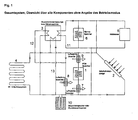
- Fig. 1 shows an example of the above-described system for seasonal use for solar cooling and for heating support using a latent heat storage 1.
- the drawing shows only the principle interconnection without specifying the exact plant engineering design.
- FIG. 2 to 7 the operation of the exemplary system in the various operating states is shown:
- Fig. Shows an overview of the various system components: latent heat storage 1, solar collector system 2, absorption heat pump or chiller 3, NT (low temperature) cooling / heating system 4, boiler 5, heat storage 6, air heat exchanger 7 to 9, Erdsondenstrom / storage or groundwater well 10th
- Fig. 2 shows the system in cooling mode, ie preferably during the day.
- the solar collector system 2 supplies the drive heat to the drive side of the chiller 3 via a heating circuit 11.
- a heat store 6 can be integrated to even out this heat delivery between the solar collector system 2 and the chiller 3.
- the cold side of the chiller 3 is connected via a refrigeration circuit 12 to the NT (low temperature) cooling / heating system 4 and thus provides usable refrigeration for cooling the room.
- the waste heat side of the chiller 3 is connected via a cooling circuit 13 with the latent heat storage (PCM memory) 1.
- This latent heat storage stores the waste heat emitted by the refrigerator.
- a boiler 5 for the additional provision of drive heat as well as a geothermal or well system 10 for additional removal of waste heat of the chiller 3 can be used.
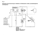
- FIGS. 2 to 4 show the operation of the system in the cooling mode, ie for the provision of cooling energy by solar thermal driven absorption chiller and time buffering of the waste heat of the chiller by means of latent heat storage (PCM memory).
- the recooling is supported in the illustrated variants in each case by a recooling, which can be used in different positions.
- a recooling instead of the recooling plant could also be a heat transfer to the ground by means of geothermal probes, ground collector or groundwater coupling.
- the Figures 3 and 4 show how Fig. 2 the system in cooling mode, ie preferably during the day, but here with an additional air heat exchanger to support the removal of waste heat of the refrigerator 3 to the environment.
- the air heat exchanger 3 can be in series - see Fig. 3 - or parallel - see Fig. 4 - Are integrated to the latent heat storage 1 in the cooling circuit 13.
- serial Integration is advantageous in terms of operation of the refrigeration system 3 with the lowest possible recooling temperature, the coming of the chiller 3 cooling water first through the air heat exchanger 9 (see Fig. 1 ) lead and then through the latent heat storage. 1
- Fig. 5 shows the re-cooling of the latent heat accumulator 1 in night mode.
- the re-cooling takes place via the air heat exchanger 7, which is connected via the return cooling circuit 13 of the refrigerator 3 with the latent heat storage.
- the wiring of the return cooling circuit 13 can be switched so that the chiller is no longer flowed through by cooling water (brine).
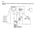
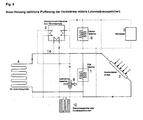
- Fig. 6 shows the solar heating operation with time buffering of the solar heat by means of latent heat storage 1:
- the solar collector system 2 is connected via the heating circuit with the NT (low temperature) cooling / heating system 4 and at the same time with the latent heat storage 1. Excess heat, which is not supplied via the heating circuit 14 to the NT (low temperature) cooling / heating system 4, takes up the latent heat storage 1.
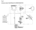
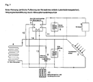
- Fig. 7 shows the solar heating mode with temporal buffering of the solar heat by means of latent heat storage, as in Fig. 6 shown, with additional use of a thermally driven heat pump 3 to support the heating operation.
- the Nutztudeabgabe the heat pump 3 via the opposite of the cold operation (see Fig. 2 ) Switched cooling circuit 13 to the heating circuit 14.
- the drive heat for the heat pump 3 is provided by means of boiler 5.
- As an environmental heat source for the heat pump 3 is an air heat exchanger 8 and / or a ground probe or groundwater well plant. These are over the opposite of the cold operation (see Fig. 2 ) switched refrigerant circuit 12 connected to the cold side of the refrigerator / heat pump 3.
Landscapes
- Engineering & Computer Science (AREA)
- Life Sciences & Earth Sciences (AREA)
- Mechanical Engineering (AREA)
- General Engineering & Computer Science (AREA)
- Sustainable Development (AREA)
- Chemical & Material Sciences (AREA)
- Combustion & Propulsion (AREA)
- Sustainable Energy (AREA)
- Physics & Mathematics (AREA)
- Thermal Sciences (AREA)
- Air Conditioning Control Device (AREA)
- Central Heating Systems (AREA)
Claims (13)
- Système de refroidissement/chauffage combiné, comprenant :- une machine de refroidissement (3) comportant une zone froide qui fournit du froid utile à un niveau de température inférieur, et une zone de chaleur perdue qui émet de la chaleur perdue à un niveau de température moyen,- un accumulateur de chaleur latente (1) pour le stockage intermédiaire de la chaleur perdue émise par la machine de refroidissement (3) en fonctionnement refroidissement,- un dispositif échangeur de chaleur ambiante ou dispositif de refroidissement de retour (7, 8, 9, 10) pour libérer dans l'environnement la chaleur perdue de l'accumulateur de chaleur latente (1) et/ou de la zone de chaleur perdue de la machine de refroidissement (3) en fonctionnement refroidissement,- une source de chaleur de chauffage (2, 5) pour emmagasiner de la chaleur dans l'accumulateur de chaleur latente (1) en fonctionnement chauffage,- au moins un dispositif (4) pour transmission du froid utile/chaleur de chauffage à un consommateur, dispositif qui peut être relié à l'accumulateur de chaleur latente (1) et à la zone froide de la machine de refroidissement (3), et- un dispositif de commande pour commutation entre le fonctionnement refroidissement et le fonctionnement chauffage,dans lequel, en fonctionnement refroidissement,
d'une part la zone froide de la machine de refroidissement (3) est reliée audit au moins un dispositif (4) de transmission de froid utile/chaleur de chauffage à un consommateur, pour fournir du froid utile, et l'accumulateur de chaleur latente (1) est relié à la zone de chaleur perdue de la machine de refroidissement (3) pour le stockage intermédiaire dans l'accumulateur de chaleur latente (1) de la chaleur perdue émise par la machine de refroidissement (3), et d'autre part l'accumulateur de chaleur latente (1) est relié au dispositif de refroidissement de retour (7, 8, 9, 10) pour libérer dans l'environnement, de manière décalée dans le temps, via le dispositif de refroidissement de retour (7, 8, 9, 10), la chaleur perdue stockée de manière intermédiaire dans l'accumulateur de chaleur latente (1),
et dans lequel, en fonctionnement chauffage,
par l'intermédiaire de la source de chaleur (2, 5), de la chaleur de chauffage est emmagasinée dans l'accumulateur de chaleur latente (1) et l'accumulateur de chaleur latente (1) est relié au dispositif (4) de transmission de froid utile/chaleur de chauffage à un consommateur pour transférer la chaleur de chauffage stockée de façon intermédiaire dans l'accumulateur de chaleur latente (1) audit au moins un dispositif (4) de transmission de froid utile/chaleur de chauffage à un consommateur. - Système selon la revendication 1, caractérisé en ce que la source de chaleur de chauffage (2, 5) peut être reliée, en fonctionnement chauffage, directement audit au moins un dispositif (4) de transmission de froid utile/chaleur de chauffage à un consommateur.
- Système selon l'une des revendications précédentes, caractérisé en ce que la source de chaleur de chauffage (2, 5) comprend un dispositif collecteur solaire (2) et/ou une chaudière de chauffage (5) et/ou un dispositif de cogénération d'énergie/de chaleur et/ou une machine de refroidissement/pompe à chaleur (3).
- Système selon l'une des revendications précédentes, caractérisé en ce que la machine de refroidissement (3) est une machine de refroidissement à absorption (3).
- Système selon l'une des revendications précédentes, caractérisé en ce que la machine de refroidissement (3) est entraînée au moins partiellement via la chaleur provenant de la source de chaleur de chauffage (2, 5).
- Système selon l'une des revendications précédentes 4 à 5, caractérisé en ce que la machine de refroidissement à absorption (3) est conçue à deux étages et comprend un étage de circuit supérieur et un étage de circuit inférieur,
en ce qu'est prévue une source de chaleur fossile pour l'entraînement de l'étage de circuit supérieur, et
en ce que l'étage de circuit inférieur est chauffé avec de l'eau chaude provenant de la source de chaleur de chauffage (2, 5). - Système selon l'une des revendications précédentes, caractérisé en ce qu'en fonctionnement refroidissement, le dispositif échangeur de chaleur ambiante (7, 8, 9, 10) est relié à l'accumulateur de chaleur latente (1) et à la zone de chaleur perdue de la machine de refroidissement (3).
- Système selon la revendication 7, caractérisé en ce que la quantité de chaleur pouvant être libérée dans l'environnement par unité de temps par le dispositif échangeur de chaleur ambiante (7, 8, 9, 10) est plus importante que la quantité de chaleur générée par unité de temps dans la zone de chaleur perdue de la machine de refroidissement (3) de sorte que la quantité de chaleur stockée de façon intermédiaire dans l'accumulateur de chaleur latente (1) diminue.
- Système selon la revendication 7, caractérisé en ce que la quantité de chaleur pouvant être libérée dans l'environnement par unité de temps par le dispositif échangeur de chaleur ambiante (7, 8, 9, 10) est moins importante que la quantité de chaleur générée par unité de temps dans la zone de chaleur perdue de la machine de refroidissement (3) de sorte que la quantité de chaleur stockée de façon intermédiaire dans l'accumulateur de chaleur latente (1) augmente.
- Système selon l'une des revendications précédentes, caractérisé en ce qu'en fonctionnement chauffage, la machine de refroidissement (3) est commutée en tant que pompe à chaleur, la zone froide absorbant de la chaleur ambiante et la zone de chaleur perdue servant de source de chaleur de chauffage.
- Système selon la revendication 10, caractérisé en ce qu'en fonctionnement chauffage, le dispositif échangeur de chaleur ambiante (7, 8, 9, 10) peut être relié à la zone froide de la pompe à chaleur (3) pour fournir de la chaleur ambiante à la zone froide de la pompe à chaleur (3).
- Système selon l'une des revendications précédentes 10 à 11, caractérisé en ce que l'entraînement de la pompe à chaleur (3) est réalisé via la chaudière de chauffage (5).
- Système selon l'une des revendications précédentes 10 à 11, caractérisé en ce que l'entraînement de la pompe à chaleur (3) s'effectue par chauffage direct.
Applications Claiming Priority (2)
| Application Number | Priority Date | Filing Date | Title |
|---|---|---|---|
| DE102005013012A DE102005013012A1 (de) | 2005-03-21 | 2005-03-21 | Latentwärmespeicher für effiziente Kühl- und Heizsysteme |
| PCT/EP2006/002606 WO2006100047A2 (fr) | 2005-03-21 | 2006-03-21 | Accumulateur de chaleur latente pour systemes de refroidissement et de chauffage performants |
Publications (2)
| Publication Number | Publication Date |
|---|---|
| EP1861663A2 EP1861663A2 (fr) | 2007-12-05 |
| EP1861663B1 true EP1861663B1 (fr) | 2011-08-24 |
Family
ID=36499038
Family Applications (1)
| Application Number | Title | Priority Date | Filing Date |
|---|---|---|---|
| EP06723606A Expired - Lifetime EP1861663B1 (fr) | 2005-03-21 | 2006-03-21 | Accumulateur de chaleur latente pour systemes de refroidissement et de chauffage performants |
Country Status (5)
| Country | Link |
|---|---|
| EP (1) | EP1861663B1 (fr) |
| AT (1) | ATE521861T1 (fr) |
| DE (1) | DE102005013012A1 (fr) |
| ES (1) | ES2372066T3 (fr) |
| WO (1) | WO2006100047A2 (fr) |
Cited By (1)
| Publication number | Priority date | Publication date | Assignee | Title |
|---|---|---|---|---|
| US12241457B1 (en) * | 2022-08-24 | 2025-03-04 | Mark H. Taylor | Renewable geothermal energy harvesting systems and methods |
Families Citing this family (26)
| Publication number | Priority date | Publication date | Assignee | Title |
|---|---|---|---|---|
| DE102008031163A1 (de) | 2008-07-03 | 2010-01-07 | Bayerisches Zentrum für Angewandte Energieforschung e.V. | Mit Latentwärmespeichermaterial (PCM) gefüllte Hohlfaser, Verfahren zu deren Herstellung sowie Verwendung dieser |
| GB2463704A (en) * | 2008-09-23 | 2010-03-24 | Solar Polar Ltd | Solar-powered absorption refrigeration system with phase-change heat store |
| GB2463705A (en) | 2008-09-23 | 2010-03-24 | Solar Polar Ltd | Solar-powered modular absorption refrigeration system |
| AU2010212610A1 (en) * | 2009-02-11 | 2011-09-08 | Vkr Holding A/S | Fluid conditioning arrangements |
| CN102395833A (zh) * | 2009-02-11 | 2012-03-28 | 阿蒂卡科技有限公司 | 流体调节装置 |
| GB2470619A (en) * | 2009-02-11 | 2010-12-01 | Artica Technologies Ltd | Phase change material compound and pack |
| IT1393132B1 (it) * | 2009-03-09 | 2012-04-11 | Eubios S P A | Impianto per la termo-regolazione di un primo ed un secondo fluido per la climatizzazione di ambienti |
| EP2567155A2 (fr) * | 2010-05-07 | 2013-03-13 | Kalús, Daniel | Système combiné d'éco-construction de bâtiments |
| DE102010019964B4 (de) * | 2010-05-08 | 2015-07-02 | Raenergie Gmbh & Co. Kg | Verfahren und Vorrichtung zur Wandlung und Speicherung thermischer Energien |
| CN101922753B (zh) * | 2010-08-27 | 2012-07-25 | 清华大学 | 一种太阳能与地热能辅助型集中供热系统 |
| DE102011007626B4 (de) * | 2011-04-18 | 2013-05-29 | Sgl Carbon Se | Latentwärmespeichereinrichtung und Betriebsverfahren für eine Latentwärmespeichereinrichtung |
| EP2766668B1 (fr) | 2011-10-13 | 2017-11-15 | Carrier Corporation | Stockage d'énergie thermique dans un système de compresseur frigorifique |
| FR2982661A1 (fr) * | 2011-11-10 | 2013-05-17 | Cythelia Expertise Et Conseil Soc De Conseils Et D Etudes En En Solaire | Installation de regulation de temperature et de production d'eau chaude et methode de mise en oeuvre d'une telle installation |
| DE102012206296A1 (de) * | 2012-04-17 | 2013-10-17 | Siemens Aktiengesellschaft | Anlage zur Speicherung und Abgabe thermischer Energie und Verfahren zu deren Betrieb |
| DE102012112646A1 (de) * | 2012-12-19 | 2014-06-26 | Rittal Gmbh & Co. Kg | PCM Speicher |
| EP2857640A1 (fr) * | 2013-10-01 | 2015-04-08 | Astrium GmbH | Dispositif doté d'au moins une unité d'accumulation de la chaleur latente |
| DE102014206415A1 (de) | 2014-04-03 | 2015-10-08 | Fraunhofer-Gesellschaft zur Förderung der angewandten Forschung e.V. | Wärmespeicheranordnung und Verfahren zum Betrieb einer solchen |
| CN104566722B (zh) * | 2014-12-31 | 2017-06-13 | 山东一村空调有限公司 | 一种自然能风窗循环软化地下水水空调 |
| CN104456799B (zh) * | 2014-12-31 | 2017-03-22 | 山东一村空调有限公司 | 一种太阳能辅热风窗循环水空调 |
| CN104566721B (zh) * | 2014-12-31 | 2018-08-21 | 山东一村空调有限公司 | 一种自然能风窗循环水空调 |
| ES2664731T3 (es) | 2015-02-09 | 2020-01-30 | Egpt Ltd | Mejora de la eficiencia en centrales energéticas |
| CN104864460B (zh) * | 2015-04-29 | 2017-10-17 | 大连理工大学 | 农村主动式太阳能蓄热地面系统 |
| CN104913364B (zh) * | 2015-06-04 | 2017-11-17 | 北京建筑大学 | 一种太阳能‑土壤源热水型吸收式热泵供热系统 |
| CN111765509B (zh) * | 2020-07-01 | 2021-02-26 | 河北工业大学 | 一种分布式风光互补双向供应能源站 |
| DE102021122516A1 (de) * | 2021-08-31 | 2023-03-02 | Viessmann Climate Solutions Se | Verfahren zum betreiben eines energieversorgungssystems und energieversorgungssystem zur bereitstellung von kühlleistung und/oder heizleistung |
| FR3151898B1 (fr) * | 2023-07-31 | 2026-01-02 | Sun Ice Energy Pte Ltd | Système de stockage d’énergie thermique comprenant un matériau a changement de phase et boucle de conditionnement thermique comprenant un tel système |
Family Cites Families (5)
| Publication number | Priority date | Publication date | Assignee | Title |
|---|---|---|---|---|
| US4169554A (en) * | 1977-10-20 | 1979-10-02 | Camp Eldon D | Solar energy system with heat pump assistance |
| US4205529A (en) * | 1978-12-04 | 1980-06-03 | The United States Of America As Represented By The United States Department Of Energy | LiCl Dehumidifier LiBr absorption chiller hybrid air conditioning system with energy recovery |
| JPS5845468A (ja) * | 1981-09-11 | 1983-03-16 | 株式会社日立製作所 | 吸収式冷凍装置 |
| US5497629A (en) * | 1993-03-23 | 1996-03-12 | Store Heat And Produce Energy, Inc. | Heating and cooling systems incorporating thermal storage |
| US5355688A (en) * | 1993-03-23 | 1994-10-18 | Shape, Inc. | Heat pump and air conditioning system incorporating thermal storage |
-
2005
- 2005-03-21 DE DE102005013012A patent/DE102005013012A1/de not_active Withdrawn
-
2006
- 2006-03-21 ES ES06723606T patent/ES2372066T3/es not_active Expired - Lifetime
- 2006-03-21 WO PCT/EP2006/002606 patent/WO2006100047A2/fr not_active Ceased
- 2006-03-21 AT AT06723606T patent/ATE521861T1/de active
- 2006-03-21 EP EP06723606A patent/EP1861663B1/fr not_active Expired - Lifetime
Cited By (1)
| Publication number | Priority date | Publication date | Assignee | Title |
|---|---|---|---|---|
| US12241457B1 (en) * | 2022-08-24 | 2025-03-04 | Mark H. Taylor | Renewable geothermal energy harvesting systems and methods |
Also Published As
| Publication number | Publication date |
|---|---|
| WO2006100047A2 (fr) | 2006-09-28 |
| ES2372066T3 (es) | 2012-01-13 |
| ATE521861T1 (de) | 2011-09-15 |
| EP1861663A2 (fr) | 2007-12-05 |
| WO2006100047A3 (fr) | 2007-10-04 |
| DE102005013012A1 (de) | 2006-09-28 |
Similar Documents
| Publication | Publication Date | Title |
|---|---|---|
| EP1861663B1 (fr) | Accumulateur de chaleur latente pour systemes de refroidissement et de chauffage performants | |
| Helm et al. | Solar heating and cooling system with absorption chiller and low temperature latent heat storage: Energetic performance and operational experience | |
| DE10300427B4 (de) | Solarsystem mit Wärmepumpe | |
| James et al. | Thermal analysis of heat pump systems using photovoltaic-thermal collectors: a review: A. James et al. | |
| KR101761176B1 (ko) | 에너지 저장 시스템 | |
| DE2807075C2 (de) | Verfahren zum Betrieb eines Heizkraftwerkes und geeignetes Heizkraftwerk | |
| EP2694885B1 (fr) | Dispositif et procédé de conversion d'énergie solaire rayonnante en courant électrique et/ou chaleur | |
| DE102008040028A1 (de) | Energiewandlungsanlage sowie Verfahren zur Gewinnung, Wandlung, Speicherung und Bereitstellung von Energie an Verbraucher | |
| EP2331880A2 (fr) | Procédé et dispositif pour obtenir de l'énergie thermique utile | |
| DE102008008652A1 (de) | Thermoelektrischer Akkumulator zur Temperaturselektiven Speicherung von Wärme in thermisch getrennten Speichern u. a. zum Zweck der Erzeugung elektrischer Energie auf der Grundlage des Seebeck-Effektes | |
| WO2007134825A2 (fr) | Dispositif et procédé de production d'énergie à partir des rayonnements solaires | |
| WO2010136381A2 (fr) | Dispositif et procédé pour refroidir des cellules solaires au moyen d'un flux d'agent de refroidissement | |
| DE102017006550A1 (de) | HVACC-Anlage zum Heizen, Lüften, Klimatisieren und zur zentralen Kältemittelversorgung für ein Gebäude | |
| EP2764298B1 (fr) | Centrale de cogénération et méthode d'opération correspondante | |
| DE102005032764A1 (de) | Sammler für Energieangebote allen Ursprungs auf regenerativer Basis | |
| DE19927027C1 (de) | Anordnung zur Gewinnung von Wärme aus Sonnenstrahlung und Umweltenergie | |
| DE2417220A1 (de) | Waermepumpeneinrichtung | |
| EP2247898B1 (fr) | Procédé de guidage de flux d'énergie thermique optimisé | |
| DE102012104996A1 (de) | Energiekonzeptsystem und Verfahren zum Betreiben eines Energiekonzeptsystems | |
| DE2509965B2 (de) | Verfahren zur Raumheizung mittels Wärmepumpenkreislauf | |
| JP4385447B2 (ja) | 蓄熱式空調設備 | |
| DE202015102294U1 (de) | Solar- und Konvektorsystemdach | |
| DE202014003951U1 (de) | Energieversorgungseinrichtung für Wärmepumpen und/oder Klimageräte | |
| DE10024044A1 (de) | Wärmepumpe bzw. Kälteanlage mit direktem Windenergieantrieb für Heizung und kühlung ohne Fremdenergie | |
| DE102014013614A1 (de) | Solarheizung mit photovoltaisch-thermischen Kollektor |
Legal Events
| Date | Code | Title | Description |
|---|---|---|---|
| PUAI | Public reference made under article 153(3) epc to a published international application that has entered the european phase |
Free format text: ORIGINAL CODE: 0009012 |
|
| 17P | Request for examination filed |
Effective date: 20071002 |
|
| AK | Designated contracting states |
Kind code of ref document: A2 Designated state(s): AT BE BG CH CY CZ DE DK EE ES FI FR GB GR HU IE IS IT LI LT LU LV MC NL PL PT RO SE SI SK TR |
|
| AX | Request for extension of the european patent |
Extension state: AL BA HR MK YU |
|
| DAX | Request for extension of the european patent (deleted) | ||
| 17Q | First examination report despatched |
Effective date: 20090130 |
|
| GRAP | Despatch of communication of intention to grant a patent |
Free format text: ORIGINAL CODE: EPIDOSNIGR1 |
|
| GRAS | Grant fee paid |
Free format text: ORIGINAL CODE: EPIDOSNIGR3 |
|
| GRAA | (expected) grant |
Free format text: ORIGINAL CODE: 0009210 |
|
| AK | Designated contracting states |
Kind code of ref document: B1 Designated state(s): AT BE BG CH CY CZ DE DK EE ES FI FR GB GR HU IE IS IT LI LT LU LV MC NL PL PT RO SE SI SK TR |
|
| REG | Reference to a national code |
Ref country code: GB Ref legal event code: FG4D Free format text: NOT ENGLISH |
|
| REG | Reference to a national code |
Ref country code: CH Ref legal event code: EP |
|
| REG | Reference to a national code |
Ref country code: IE Ref legal event code: FG4D Free format text: LANGUAGE OF EP DOCUMENT: GERMAN |
|
| REG | Reference to a national code |
Ref country code: DE Ref legal event code: R096 Ref document number: 502006010071 Country of ref document: DE Effective date: 20111110 |
|
| REG | Reference to a national code |
Ref country code: NL Ref legal event code: VDEP Effective date: 20110824 |
|
| REG | Reference to a national code |
Ref country code: ES Ref legal event code: FG2A Ref document number: 2372066 Country of ref document: ES Kind code of ref document: T3 Effective date: 20120113 |
|
| LTIE | Lt: invalidation of european patent or patent extension |
Effective date: 20110824 |
|
| PG25 | Lapsed in a contracting state [announced via postgrant information from national office to epo] |
Ref country code: LT Free format text: LAPSE BECAUSE OF FAILURE TO SUBMIT A TRANSLATION OF THE DESCRIPTION OR TO PAY THE FEE WITHIN THE PRESCRIBED TIME-LIMIT Effective date: 20110824 Ref country code: NL Free format text: LAPSE BECAUSE OF FAILURE TO SUBMIT A TRANSLATION OF THE DESCRIPTION OR TO PAY THE FEE WITHIN THE PRESCRIBED TIME-LIMIT Effective date: 20110824 Ref country code: IS Free format text: LAPSE BECAUSE OF FAILURE TO SUBMIT A TRANSLATION OF THE DESCRIPTION OR TO PAY THE FEE WITHIN THE PRESCRIBED TIME-LIMIT Effective date: 20111224 Ref country code: FI Free format text: LAPSE BECAUSE OF FAILURE TO SUBMIT A TRANSLATION OF THE DESCRIPTION OR TO PAY THE FEE WITHIN THE PRESCRIBED TIME-LIMIT Effective date: 20110824 Ref country code: SE Free format text: LAPSE BECAUSE OF FAILURE TO SUBMIT A TRANSLATION OF THE DESCRIPTION OR TO PAY THE FEE WITHIN THE PRESCRIBED TIME-LIMIT Effective date: 20110824 Ref country code: PT Free format text: LAPSE BECAUSE OF FAILURE TO SUBMIT A TRANSLATION OF THE DESCRIPTION OR TO PAY THE FEE WITHIN THE PRESCRIBED TIME-LIMIT Effective date: 20111226 |
|
| PG25 | Lapsed in a contracting state [announced via postgrant information from national office to epo] |
Ref country code: SI Free format text: LAPSE BECAUSE OF FAILURE TO SUBMIT A TRANSLATION OF THE DESCRIPTION OR TO PAY THE FEE WITHIN THE PRESCRIBED TIME-LIMIT Effective date: 20110824 Ref country code: LV Free format text: LAPSE BECAUSE OF FAILURE TO SUBMIT A TRANSLATION OF THE DESCRIPTION OR TO PAY THE FEE WITHIN THE PRESCRIBED TIME-LIMIT Effective date: 20110824 Ref country code: CY Free format text: LAPSE BECAUSE OF FAILURE TO SUBMIT A TRANSLATION OF THE DESCRIPTION OR TO PAY THE FEE WITHIN THE PRESCRIBED TIME-LIMIT Effective date: 20110824 Ref country code: PL Free format text: LAPSE BECAUSE OF FAILURE TO SUBMIT A TRANSLATION OF THE DESCRIPTION OR TO PAY THE FEE WITHIN THE PRESCRIBED TIME-LIMIT Effective date: 20110824 Ref country code: GR Free format text: LAPSE BECAUSE OF FAILURE TO SUBMIT A TRANSLATION OF THE DESCRIPTION OR TO PAY THE FEE WITHIN THE PRESCRIBED TIME-LIMIT Effective date: 20111125 |
|
| REG | Reference to a national code |
Ref country code: IE Ref legal event code: FD4D |
|
| PG25 | Lapsed in a contracting state [announced via postgrant information from national office to epo] |
Ref country code: SK Free format text: LAPSE BECAUSE OF FAILURE TO SUBMIT A TRANSLATION OF THE DESCRIPTION OR TO PAY THE FEE WITHIN THE PRESCRIBED TIME-LIMIT Effective date: 20110824 Ref country code: CZ Free format text: LAPSE BECAUSE OF FAILURE TO SUBMIT A TRANSLATION OF THE DESCRIPTION OR TO PAY THE FEE WITHIN THE PRESCRIBED TIME-LIMIT Effective date: 20110824 Ref country code: IE Free format text: LAPSE BECAUSE OF FAILURE TO SUBMIT A TRANSLATION OF THE DESCRIPTION OR TO PAY THE FEE WITHIN THE PRESCRIBED TIME-LIMIT Effective date: 20110824 |
|
| PG25 | Lapsed in a contracting state [announced via postgrant information from national office to epo] |
Ref country code: RO Free format text: LAPSE BECAUSE OF FAILURE TO SUBMIT A TRANSLATION OF THE DESCRIPTION OR TO PAY THE FEE WITHIN THE PRESCRIBED TIME-LIMIT Effective date: 20110824 Ref country code: EE Free format text: LAPSE BECAUSE OF FAILURE TO SUBMIT A TRANSLATION OF THE DESCRIPTION OR TO PAY THE FEE WITHIN THE PRESCRIBED TIME-LIMIT Effective date: 20110824 |
|
| PG25 | Lapsed in a contracting state [announced via postgrant information from national office to epo] |
Ref country code: DK Free format text: LAPSE BECAUSE OF FAILURE TO SUBMIT A TRANSLATION OF THE DESCRIPTION OR TO PAY THE FEE WITHIN THE PRESCRIBED TIME-LIMIT Effective date: 20110824 |
|
| PLBE | No opposition filed within time limit |
Free format text: ORIGINAL CODE: 0009261 |
|
| STAA | Information on the status of an ep patent application or granted ep patent |
Free format text: STATUS: NO OPPOSITION FILED WITHIN TIME LIMIT |
|
| 26N | No opposition filed |
Effective date: 20120525 |
|
| REG | Reference to a national code |
Ref country code: DE Ref legal event code: R097 Ref document number: 502006010071 Country of ref document: DE Effective date: 20120525 |
|
| BERE | Be: lapsed |
Owner name: ZAE BAYERN BAYERISCHES ZENTRUM FUR ANGEWANDTE ENE Effective date: 20120331 |
|
| PG25 | Lapsed in a contracting state [announced via postgrant information from national office to epo] |
Ref country code: MC Free format text: LAPSE BECAUSE OF NON-PAYMENT OF DUE FEES Effective date: 20120331 |
|
| REG | Reference to a national code |
Ref country code: CH Ref legal event code: PL |
|
| PG25 | Lapsed in a contracting state [announced via postgrant information from national office to epo] |
Ref country code: CH Free format text: LAPSE BECAUSE OF NON-PAYMENT OF DUE FEES Effective date: 20120331 Ref country code: LI Free format text: LAPSE BECAUSE OF NON-PAYMENT OF DUE FEES Effective date: 20120331 Ref country code: BE Free format text: LAPSE BECAUSE OF NON-PAYMENT OF DUE FEES Effective date: 20120331 |
|
| REG | Reference to a national code |
Ref country code: AT Ref legal event code: MM01 Ref document number: 521861 Country of ref document: AT Kind code of ref document: T Effective date: 20120321 |
|
| PG25 | Lapsed in a contracting state [announced via postgrant information from national office to epo] |
Ref country code: BG Free format text: LAPSE BECAUSE OF FAILURE TO SUBMIT A TRANSLATION OF THE DESCRIPTION OR TO PAY THE FEE WITHIN THE PRESCRIBED TIME-LIMIT Effective date: 20111124 |
|
| PG25 | Lapsed in a contracting state [announced via postgrant information from national office to epo] |
Ref country code: AT Free format text: LAPSE BECAUSE OF NON-PAYMENT OF DUE FEES Effective date: 20120321 |
|
| PG25 | Lapsed in a contracting state [announced via postgrant information from national office to epo] |
Ref country code: TR Free format text: LAPSE BECAUSE OF FAILURE TO SUBMIT A TRANSLATION OF THE DESCRIPTION OR TO PAY THE FEE WITHIN THE PRESCRIBED TIME-LIMIT Effective date: 20110824 |
|
| PG25 | Lapsed in a contracting state [announced via postgrant information from national office to epo] |
Ref country code: LU Free format text: LAPSE BECAUSE OF NON-PAYMENT OF DUE FEES Effective date: 20120321 |
|
| PG25 | Lapsed in a contracting state [announced via postgrant information from national office to epo] |
Ref country code: HU Free format text: LAPSE BECAUSE OF FAILURE TO SUBMIT A TRANSLATION OF THE DESCRIPTION OR TO PAY THE FEE WITHIN THE PRESCRIBED TIME-LIMIT Effective date: 20060321 |
|
| REG | Reference to a national code |
Ref country code: FR Ref legal event code: PLFP Year of fee payment: 11 |
|
| REG | Reference to a national code |
Ref country code: FR Ref legal event code: PLFP Year of fee payment: 12 |
|
| REG | Reference to a national code |
Ref country code: FR Ref legal event code: PLFP Year of fee payment: 13 |
|
| PGFP | Annual fee paid to national office [announced via postgrant information from national office to epo] |
Ref country code: IT Payment date: 20200325 Year of fee payment: 15 Ref country code: DE Payment date: 20200302 Year of fee payment: 15 Ref country code: GB Payment date: 20200325 Year of fee payment: 15 |
|
| PGFP | Annual fee paid to national office [announced via postgrant information from national office to epo] |
Ref country code: FR Payment date: 20200324 Year of fee payment: 15 |
|
| PGFP | Annual fee paid to national office [announced via postgrant information from national office to epo] |
Ref country code: ES Payment date: 20200421 Year of fee payment: 15 |
|
| REG | Reference to a national code |
Ref country code: DE Ref legal event code: R119 Ref document number: 502006010071 Country of ref document: DE |
|
| GBPC | Gb: european patent ceased through non-payment of renewal fee |
Effective date: 20210321 |
|
| PG25 | Lapsed in a contracting state [announced via postgrant information from national office to epo] |
Ref country code: GB Free format text: LAPSE BECAUSE OF NON-PAYMENT OF DUE FEES Effective date: 20210321 Ref country code: FR Free format text: LAPSE BECAUSE OF NON-PAYMENT OF DUE FEES Effective date: 20210331 Ref country code: DE Free format text: LAPSE BECAUSE OF NON-PAYMENT OF DUE FEES Effective date: 20211001 |
|
| PG25 | Lapsed in a contracting state [announced via postgrant information from national office to epo] |
Ref country code: IT Free format text: LAPSE BECAUSE OF NON-PAYMENT OF DUE FEES Effective date: 20210321 |
|
| REG | Reference to a national code |
Ref country code: ES Ref legal event code: FD2A Effective date: 20220523 |
|
| PG25 | Lapsed in a contracting state [announced via postgrant information from national office to epo] |
Ref country code: ES Free format text: LAPSE BECAUSE OF NON-PAYMENT OF DUE FEES Effective date: 20210322 |