EP1860742A1 - Support de contact pour une fiche ou une prise - Google Patents
Support de contact pour une fiche ou une prise Download PDFInfo
- Publication number
- EP1860742A1 EP1860742A1 EP20070009762 EP07009762A EP1860742A1 EP 1860742 A1 EP1860742 A1 EP 1860742A1 EP 20070009762 EP20070009762 EP 20070009762 EP 07009762 A EP07009762 A EP 07009762A EP 1860742 A1 EP1860742 A1 EP 1860742A1
- Authority
- EP
- European Patent Office
- Prior art keywords
- contact
- contact holder
- base part
- holder according
- protective part
- Prior art date
- Legal status (The legal status is an assumption and is not a legal conclusion. Google has not performed a legal analysis and makes no representation as to the accuracy of the status listed.)
- Withdrawn
Links
Images


Classifications
-
- H—ELECTRICITY
- H01—ELECTRIC ELEMENTS
- H01R—ELECTRICALLY-CONDUCTIVE CONNECTIONS; STRUCTURAL ASSOCIATIONS OF A PLURALITY OF MUTUALLY-INSULATED ELECTRICAL CONNECTING ELEMENTS; COUPLING DEVICES; CURRENT COLLECTORS
- H01R13/00—Details of coupling devices of the kinds covered by groups H01R12/70 or H01R24/00 - H01R33/00
- H01R13/46—Bases; Cases
- H01R13/502—Bases; Cases composed of different pieces
- H01R13/506—Bases; Cases composed of different pieces assembled by snap action of the parts
-
- H—ELECTRICITY
- H01—ELECTRIC ELEMENTS
- H01R—ELECTRICALLY-CONDUCTIVE CONNECTIONS; STRUCTURAL ASSOCIATIONS OF A PLURALITY OF MUTUALLY-INSULATED ELECTRICAL CONNECTING ELEMENTS; COUPLING DEVICES; CURRENT COLLECTORS
- H01R13/00—Details of coupling devices of the kinds covered by groups H01R12/70 or H01R24/00 - H01R33/00
- H01R13/46—Bases; Cases
- H01R13/52—Dustproof, splashproof, drip-proof, waterproof, or flameproof cases
- H01R13/521—Sealing between contact members and housing, e.g. sealing insert
-
- H—ELECTRICITY
- H01—ELECTRIC ELEMENTS
- H01R—ELECTRICALLY-CONDUCTIVE CONNECTIONS; STRUCTURAL ASSOCIATIONS OF A PLURALITY OF MUTUALLY-INSULATED ELECTRICAL CONNECTING ELEMENTS; COUPLING DEVICES; CURRENT COLLECTORS
- H01R13/00—Details of coupling devices of the kinds covered by groups H01R12/70 or H01R24/00 - H01R33/00
- H01R13/02—Contact members
- H01R13/04—Pins or blades for co-operation with sockets
-
- H—ELECTRICITY
- H01—ELECTRIC ELEMENTS
- H01R—ELECTRICALLY-CONDUCTIVE CONNECTIONS; STRUCTURAL ASSOCIATIONS OF A PLURALITY OF MUTUALLY-INSULATED ELECTRICAL CONNECTING ELEMENTS; COUPLING DEVICES; CURRENT COLLECTORS
- H01R13/00—Details of coupling devices of the kinds covered by groups H01R12/70 or H01R24/00 - H01R33/00
- H01R13/40—Securing contact members in or to a base or case; Insulating of contact members
- H01R13/42—Securing in a demountable manner
- H01R13/424—Securing in base or case composed of a plurality of insulating parts having at least one resilient insulating part
Definitions
- the invention relates to a contact holder for a plug or a socket, in particular for a plug or a socket for a connection between a towing vehicle and a trailer, comprising a base part having at least one longitudinally extending opening into which a contact can be inserted.
- the invention further relates to a contact unit, comprising a contact holder and at least one contact, as well as a contact or a plurality of contacts for a contact holder.
- plugs or sockets for an electrical connection of trailer vehicles with a contact holder, which has a variety of recordings, in which contacts such as pins or sockets can be used.
- the contact holders are either formed integrally with a housing or as a separate component that can be used after a population with contacts in a housing.
- the number and / or location of the contacts is defined by ISO standards and / or DIN standards.
- a contact holder for a socket or a plug for a plug connection for the electrical connection known from motor vehicles having a body in which a plurality, in the longitudinal direction of the body and extending therethrough openings for receiving contacts are provided.
- the contact holder can be inserted with inserted contacts in a hollow cylindrical part of a housing of a socket or a plug and locked with this part.
- a contact holder for a plug or a socket comprising a base part having at least one longitudinally extending opening into which at least one contact can be inserted, wherein the base part is at least partially insertable into a protective part, so that the contact inserted in the base part is protected at least in the radial direction by the protective part and is accessible for use, and the protective part with inserted base part can be inserted into a housing of the plug or socket.
- the protective part ensures that the contacts inserted into the openings are better protected at least in the radial direction.
- the protective part is formed for example as a hollow cylinder, as a ring or as a cap, in which an associated base part can be used.
- the protective part has a sealing cap on a front side.
- a sealing cap on a front side.
- materials for the sealing cap ordinary sealing materials are used, which are preferably elastic.
- the sealing cap is formed as an insert for injection molding.
- the sealing cap is thus connected during the molding of the protective part as an injection molded part in a simple manner with this.
- the connection between the sealing cap and the protective part is strengthened in one embodiment by noses and similar formations.
- the sealing cap is locked with the molded protective part.
- the sealing cap has at least one passage for the at least one contact against which an inserted contact rests flush.
- a diameter of the passage may be selected substantially equal to or slightly smaller than a diameter of the male contact.
- the protective part is formed with an ejection unit which comprises a rod element acted upon by a spring and movable in the axial direction relative to the contact holder.
- ejection units are well known. They are preferably provided at a socket to facilitate removal of an inserted plug by the preloaded spring.
- a housing of the ejection unit is integrally formed in one embodiment with the protective part, for example as Injection molded part.
- the ejection unit is formed as a separate component, which is locked to a body of the protective part, glued, screwed, riveted and / or connected in other ways.
- the base part and the protective part are locked together.
- a simple, tool-free detachable connection of the base part with the protective part is possible.
- contacts used in the base part for maintenance and / or due to a defect are readily accessible at any time by removal of the protective part.
- the protective part has on its outer periphery at least one projection and / or a recess, by means of which it can be positioned in the housing of the plug or of the socket.
- the inserted contact holder can be fixed in the housing, for example, by a closure cap of the housing and / or by rotation, for example by a thread or a bayonet closure.
- the opening has upper and lower stop surfaces for axially positioning a contact with a tapered region.
- the contacts are radially engageable in the corresponding openings.
- a particularly easy assembly and / or disassembly of the contacts is possible.
- a contact unit comprising a contact holder described above and at least one inserted contact.
- a contact for a contact holder described above wherein the contact is formed in two parts, comprising a contact piece and a connection piece.
- the contact piece is used to make contact with a corresponding second contact. It is formed, for example, as a contact pin or as a socket.
- the connection piece is used to connect to a conductor.
- the connector has, for example, elements for a crimp connection with a conductor.
- the contact piece of the contact is formed as a deep-drawn part.
- the formation as a deep-drawn part allows cost-effective production with high accuracy.
- the connecting piece is formed as a stamped part.
- the connection piece can be inserted into an opening at a rear end of a deep-drawn or turned contact piece and can be connected thereto, for example by deformation.
- the connecting piece has a stop which is formed by bending the stamped part. This is inexpensive contact with a tapered region produced, which is axially secured positionable in a corresponding opening of the contact holder.
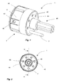
- FIG. 1 and 2 show schematically a perspective view of a contact unit 1 and a plan view of the contact unit 1, comprising a contact holder 2 and a contact inserted therein 3.
- the illustrated contact unit 1 are regularly distributed over the circumference of the contact unit 1 seven contacts 3 can be used , however, embodiments are also conceivable which have a deviating arrangement and / or number of contacts 3. For example, fifteen receptacles are provided for contacts in a 15-pole embodiment, not shown. The number and / or arrangement of contacts is determined for example for certain plugs and sockets by appropriate ISO standards or DIN standards.
- the illustrated contact unit 1 is suitable, for example, for use in a socket according to DIN ISO 7638. However, the invention is not limited to contact units for such sockets.
- the contact holder 2 comprises a protective part 4 and a base part not visible in FIG. 1, which is inserted into the protective part 4.
- the base part and the protective part 4 have in the illustrated embodiment complementary locking lugs 50 and recesses 40, via which they can be locked together.
- the protective part 4 shown further has projections 42, by means of which the contact holder 2 can be positioned in a housing, not shown, in a specific orientation.
- the protective part 4 is formed on its front side with a sealing cap 44, by means of which a connection region of the contacts 3, not visible in FIG. 1, can be protected against moisture and / or dirt.
- the sealing cap 44 has passages 45 for the contacts 3, wherein the sealing cap 44 bears flush against the contact 3.
- the contact holder 2 shown is preferably used as already described in the housing of a socket according to DIN ISO 7638.
- the contact holder 2 has an ejection unit 46.
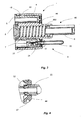
- FIG. 3 shows a sectional view of the contact unit 1 along the sectional plane III-III according to FIG. 2.
- a housing 460 of the ejection unit 46 is formed on the protective part 4.
- the ejection unit 46 comprises a rod element 6, which is acted upon by a spring 7 and is movable in the axial direction relative to the contact unit 1.
- the rod member 6 and the spring 7 are inserted into the housing 460 of the ejection unit and secured by an end cap 8.
- the illustrated contact 3 is in two parts with a contact piece 30 and a connector 32 ausformt, which are crimped together in the illustrated embodiment.
- the connecting piece 32 is formed in the illustrated embodiment as a stamped part and has a stop 34 which is formed by bending of the stamped part.
- a conductor can be fastened in the usual way. The attachment of the conductor can advantageously take place before insertion of the contact 3 into an opening 52 of the base part 5 or by removal from the opening 52. This allows easy handling.
- the illustrated contact piece 30 can be manufactured, for example, by deep drawing and is shaped as a hollow body.
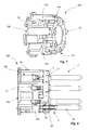
- FIG. 4 is an enlarged view of the connecting portion IV of the contact piece 30 with the connector 32 shown in FIG. 3. As seen in Fig. 4, the connector 32 is inserted for connection with the contact piece 30 in this and the contact piece 30 for a connection bent into corresponding recesses on the connector.
- the sealing cap 44 is preferably connected in the manufacture of the protective part by injection molding with this. As can be seen in FIGS. 3 and 4, a connection of the sealing cap 44 to the protective part 4 is improved by lugs 47.
- Fig. 5 is a perspective view of the base member 5 with a contact 3 inserted.
- the base member 5 has longitudinally extending openings 52 into which contacts 3 are insertable.
- the contacts are 3 for this radially into the openings 52 latched.
- the openings 52 have clamping region 53 with an upper and a lower stop surface 54, 55 for the axial positioning of the contact 3.
- the illustrated contact 3 has for this purpose a corresponding tapered region between the contact piece 30 and the stop 34.
- the upper abutment surface 54 is adjoined by an edge 56, which improves a guidance of the contact in the opening 52.
- webs 57 are provided.
- the base part 5 is further formed with locking lugs 50 already described for latching with the protective part shown in Fig. 6.
- Fig. 6 is a perspective view of the protective part 4 without inserted base part.
- the illustrated protective part 4 is formed as a hollow cylinder with a closed front side 4A.
- the housing 460 of the ejection unit 46 already described extends.
- the protective part 4 does not have a closed front side 4A.
- On the front side 4A a sealing cap 44 is arranged, which seals the interior of the protective part 4.
- the sealing cap 44 and the front side 4A of the protective part 4 are formed with passages 45, through which the contacts 3 shown in FIG. 5, for example, can be carried out.
- the protective part 4 can thus be inserted from a rear side 4B of the protective part 4 into the latter, wherein the latching noses 50 of the base part 5 engage in the recesses 40 of the protective part 4.
- the scope of the illustrated protective part 4 has a peripheral edge 48, by which a sealing surface of the protective part 4 is limited. About the sealing surface takes place in the illustrated embodiment, the sealing of the protective part 4 to a housing, not shown.
- Fig. 7 is a perspective view of a base part 105 according to a second embodiment of the invention.
- the base part 105 essentially corresponds to the base part 5 according to FIGS. 1 to 6, and identical reference symbols are used for the same components.
- the base part 105 is, for example, with that shown in Fig. 3 Protective part 4 by means of the locking lugs 50 latched.
- the base part 105 has recesses 152, wherein the recesses 152 are designed as grooves arranged on the outer circumference and having a clamping region 53 in the axial direction. In contrast to the embodiment according to FIGS. 1 to 5, however, no webs 57 are present.
- recesses 152 By such recesses 152 a simple engagement of the male contacts 3 in the base part 105 by moving the contacts 3 in the radial direction is possible. In order for a handling of a corresponding contact holder is particularly simple and mechanical stress on the contacts and / or on the associated conductor during insertion can be minimized.
- the recesses 152 are connected to chambers 153, the function of which will be explained below with reference to FIG. 9.
- the base part 105 has a circumferential groove or step 154, on which a locking ring, not shown in FIG. 7, can be latched.
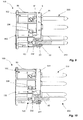
- FIG. 8 shows the base part 105 according to FIG. 7 in a partially cut-free representation, into which contacts 3 according to FIGS. 3 and 5 are inserted, each with a contact piece 30 and a connecting piece 32, four contacts 3 being visible in FIG ,
- a securing ring 9 is latched onto the step 154 of the base part 105 shown in FIG. 7 as secondary locking.
- the circlip 9 rests with its inner circumference on the contacts 3 and prevents skewing of the contacts 3.
- the circlip 9 shown has lugs 90 which engage in the contacts 3.
- the circlip 9 also ensures that all contacts 3 are properly latched in the recesses 152, since without a sufficient locking of the contacts 3 in the recesses 152 of the retaining ring 9 is not attached to the base member 105.
- the retaining ring 9 further has at its periphery a plurality, in the illustrated embodiment, four, axially extending latching arms 92 for latching with the base part 105 on.
- FIG. 9 shows the base part 105 according to FIG. 7 in a partially cutaway view, into which contacts 203 according to another exemplary embodiment are inserted, wherein in FIG. 9 four contacts 203 are visible.
- the contacts 203 are integrally formed, for example, as a rotating part.
- the contacts 203 grooves 231 in the circumferential direction.
- the lugs 90 of the attached securing ring 9 also engage in the grooves 231.
- At connection ends of the contacts 203 bores 232 are provided, in which conductors not shown by means of screws 236 are fastened.
- the screws 236 can be arranged in the chambers 153.
- FIG. 10 shows a structural unit similar to FIG. 9 with a base part 105 and contacts 203 latched therein.
- a securing ring 309 which essentially corresponds to the securing ring 9 according to FIG. 9 and also essentially fulfills the same functions is latched to the base part 105.
- the securing ring 309 has no noses and no slots in the axial direction.
- Fig. 11 shows a perspective, partially exploded view of the assembly of FIG. 10 with the locking ring 309 and inserted contacts 203.
- the locking ring 309 at its periphery a plurality, in the illustrated embodiment three, in Axially extending latching arms 92, via which the locking ring 309 can be latched to the base part 105.
- contact surfaces 93 for the contacts 3, 203 are provided on the inner circumference of the illustrated securing ring 309.
Applications Claiming Priority (1)
| Application Number | Priority Date | Filing Date | Title |
|---|---|---|---|
| DE102006025611A DE102006025611B3 (de) | 2006-05-24 | 2006-05-24 | Kontakthalter für einen Stecker oder eine Steckdose |
Publications (1)
| Publication Number | Publication Date |
|---|---|
| EP1860742A1 true EP1860742A1 (fr) | 2007-11-28 |
Family
ID=38293226
Family Applications (1)
| Application Number | Title | Priority Date | Filing Date |
|---|---|---|---|
| EP20070009762 Withdrawn EP1860742A1 (fr) | 2006-05-24 | 2007-05-16 | Support de contact pour une fiche ou une prise |
Country Status (2)
| Country | Link |
|---|---|
| EP (1) | EP1860742A1 (fr) |
| DE (1) | DE102006025611B3 (fr) |
Cited By (3)
| Publication number | Priority date | Publication date | Assignee | Title |
|---|---|---|---|---|
| DE102010030958A1 (de) * | 2010-07-05 | 2012-01-05 | Tyco Electronics Amp Gmbh | Anordnung, insbesondere Stecker und Verfahren zur Herstellung |
| CN104934745A (zh) * | 2015-06-09 | 2015-09-23 | 西安航空制动科技有限公司 | 一种空心快速拆卸电连接器 |
| CN107230860A (zh) * | 2016-03-23 | 2017-10-03 | 泰连德国有限公司 | 功率电接触装置、可更换功率电接触模块和功率电连接器 |
Families Citing this family (5)
| Publication number | Priority date | Publication date | Assignee | Title |
|---|---|---|---|---|
| DE102009021594B4 (de) * | 2009-04-09 | 2018-04-12 | Phoenix Contact Gmbh & Co. Kg | Elektrischer Steckverbinder und elektrische Steckverbindung sowie Verfahren zum Anschließen der Andern eines mehradrigen Kabels an einen elektrischen Steckverbinder |
| DE102015213734A1 (de) | 2015-07-21 | 2017-01-26 | Itt Manufacturing Enterprises Llc | Steckverbinder |
| DE102016105465A1 (de) | 2016-03-23 | 2017-09-28 | Escha GmbH & Co. KG | Mit einem verdrillte Adernpaare aufweisenden Kabel verbundener Steckverbinder |
| DE202019101871U1 (de) | 2019-04-02 | 2019-04-11 | Apparatebau Kirchheim-Teck Gmbh | Kontaktelement mit Abdichtung für eine Steckverbindung |
| DE102019208782B4 (de) * | 2019-06-06 | 2022-12-01 | Franz Binder Gmbh + Co. Elektrische Bauelemente Kg | Steckverbinder und Lösewerkzeug zum Trennen eines solchen Steckverbinders sowie entsprechendes Verfahren |
Citations (6)
| Publication number | Priority date | Publication date | Assignee | Title |
|---|---|---|---|---|
| US3836843A (en) * | 1971-10-26 | 1974-09-17 | E Yonce | Electric circuit tester connector for highway vehicles |
| US5066242A (en) * | 1990-10-15 | 1991-11-19 | Molex Incorporated | Environment-proof electrical connector assembly |
| EP0544630A2 (fr) * | 1991-11-28 | 1993-06-02 | MENBER'S S.p.A. | Connecteur électrique, en particulier pour connecter un véhicule tracteur et un véhicule tracté avec système d'antiblockage |
| EP0610681A2 (fr) * | 1993-02-12 | 1994-08-17 | MENBER'S S.p.A. | Porte-contact pour douille ou fiche d'un connecteur electrique |
| US5399110A (en) * | 1994-02-04 | 1995-03-21 | General Motors Corporation | Two piece male pin terminal |
| EP1617523A1 (fr) * | 2004-07-16 | 2006-01-18 | IEMMEGI S.r.l. | Dispositif de connexion multipolaire de sécurité |
Family Cites Families (3)
| Publication number | Priority date | Publication date | Assignee | Title |
|---|---|---|---|---|
| DE4006309A1 (de) * | 1990-03-01 | 1991-09-05 | Gebhard Dietrich | Kontakttraeger fuer eine steckdose oder einen stecker fuer eine steckverbindung fuer den elektrischen anschluss von kraftfahrzeuganhaengern |
| DE69702436T2 (de) * | 1997-03-19 | 2001-01-25 | Air Lb International Luxembour | Steckverbinder für eine gedruckte Leiterplatte |
| DE20318251U1 (de) * | 2003-11-24 | 2004-03-18 | Coninvers Elektrotechnische Bauelemente Gmbh | Elektrische Steckverbindung und Steckverbinder |
-
2006
- 2006-05-24 DE DE102006025611A patent/DE102006025611B3/de active Active
-
2007
- 2007-05-16 EP EP20070009762 patent/EP1860742A1/fr not_active Withdrawn
Patent Citations (6)
| Publication number | Priority date | Publication date | Assignee | Title |
|---|---|---|---|---|
| US3836843A (en) * | 1971-10-26 | 1974-09-17 | E Yonce | Electric circuit tester connector for highway vehicles |
| US5066242A (en) * | 1990-10-15 | 1991-11-19 | Molex Incorporated | Environment-proof electrical connector assembly |
| EP0544630A2 (fr) * | 1991-11-28 | 1993-06-02 | MENBER'S S.p.A. | Connecteur électrique, en particulier pour connecter un véhicule tracteur et un véhicule tracté avec système d'antiblockage |
| EP0610681A2 (fr) * | 1993-02-12 | 1994-08-17 | MENBER'S S.p.A. | Porte-contact pour douille ou fiche d'un connecteur electrique |
| US5399110A (en) * | 1994-02-04 | 1995-03-21 | General Motors Corporation | Two piece male pin terminal |
| EP1617523A1 (fr) * | 2004-07-16 | 2006-01-18 | IEMMEGI S.r.l. | Dispositif de connexion multipolaire de sécurité |
Cited By (7)
| Publication number | Priority date | Publication date | Assignee | Title |
|---|---|---|---|---|
| DE102010030958A1 (de) * | 2010-07-05 | 2012-01-05 | Tyco Electronics Amp Gmbh | Anordnung, insbesondere Stecker und Verfahren zur Herstellung |
| DE102010030958B4 (de) * | 2010-07-05 | 2012-02-02 | Tyco Electronics Amp Gmbh | Anordnung, insbesondere Stecker und Verfahren zur Herstellung |
| CN104934745A (zh) * | 2015-06-09 | 2015-09-23 | 西安航空制动科技有限公司 | 一种空心快速拆卸电连接器 |
| CN104934745B (zh) * | 2015-06-09 | 2017-10-20 | 西安航空制动科技有限公司 | 一种空心快速拆卸电连接器 |
| CN107230860A (zh) * | 2016-03-23 | 2017-10-03 | 泰连德国有限公司 | 功率电接触装置、可更换功率电接触模块和功率电连接器 |
| EP3223371A3 (fr) * | 2016-03-23 | 2017-11-29 | TE Connectivity Germany GmbH | Dispositif de contact électrique de puissance, module de contact électrique de puissance échangeable et connecteur électrique de puissance |
| CN107230860B (zh) * | 2016-03-23 | 2021-07-27 | 泰连德国有限公司 | 功率电接触装置、可更换功率电接触模块和功率电连接器 |
Also Published As
| Publication number | Publication date |
|---|---|
| DE102006025611B3 (de) | 2007-12-06 |
Similar Documents
| Publication | Publication Date | Title |
|---|---|---|
| DE102006016882B4 (de) | Steckverbinder | |
| EP1851830B1 (fr) | Systeme de liaison, notamment systeme de connexion electrique | |
| EP1275173B1 (fr) | Connecteur comportant une douille | |
| EP1860742A1 (fr) | Support de contact pour une fiche ou une prise | |
| WO2006133925A1 (fr) | Connecteur electrique, element male et element femelle | |
| EP1182739A2 (fr) | Contact à haute intensité | |
| DE102006036297A1 (de) | Buchsenartiges Kontaktelement und Herstellungsverfahren für ein Buchsenartiges Kontaktelement | |
| EP2072844B1 (fr) | Articulation à rotule | |
| DE19848289C2 (de) | Verriegelungsvorrichtung eines Kappenteils | |
| DE102020115021A1 (de) | Vorrichtung zum Verbinden zweier röhrenförmiger Objekte | |
| EP1672751B1 (fr) | Douille de lampe | |
| DE102012206102A1 (de) | Elektrischer Verbinder | |
| EP3143320A1 (fr) | Unité de raccordement destinée à un dispositif d'accouplement, en particulier à un raccord multiple | |
| DE4306806B4 (de) | In einer Platte befestigbarer elektrischer Verbinder | |
| EP1720222B1 (fr) | Connecteur électrique, notamment pour des systèmes d' allumage d' airbag | |
| DE102006027311B3 (de) | Elektrischer Steckverbinder und Kontakthalter hierfür | |
| DE1765099B2 (de) | Elektrische steckvorrichtung | |
| EP3859896A1 (fr) | Douille de contact pour un insert porte-contact d'une prise | |
| DE2337043C2 (de) | Elektrische Steckverbindung | |
| DE202011000750U1 (de) | Steckverbindungsanordnung für elektrische Leiter | |
| DE4407583C1 (de) | Elektrisches Anschlußteil | |
| EP1462310B1 (fr) | Module de colonne de direction | |
| EP2760085A1 (fr) | Module adaptateur enfichable et son procédé de fabrication | |
| EP1548895A2 (fr) | Disposition de montage de connecteur électrique | |
| EP1164662B1 (fr) | Contact femelle |
Legal Events
| Date | Code | Title | Description |
|---|---|---|---|
| PUAI | Public reference made under article 153(3) epc to a published international application that has entered the european phase |
Free format text: ORIGINAL CODE: 0009012 |
|
| AK | Designated contracting states |
Kind code of ref document: A1 Designated state(s): AT BE BG CH CY CZ DE DK EE ES FI FR GB GR HU IE IS IT LI LT LU LV MC MT NL PL PT RO SE SI SK TR |
|
| AX | Request for extension of the european patent |
Extension state: AL BA HR MK YU |
|
| 17P | Request for examination filed |
Effective date: 20080506 |
|
| AKX | Designation fees paid |
Designated state(s): AT BE BG CH CY CZ DE DK EE ES FI FR GB GR HU IE IS IT LI LT LU LV MC MT NL PL PT RO SE SI SK TR |
|
| 17Q | First examination report despatched |
Effective date: 20110712 |
|
| GRAP | Despatch of communication of intention to grant a patent |
Free format text: ORIGINAL CODE: EPIDOSNIGR1 |
|
| INTG | Intention to grant announced |
Effective date: 20151209 |
|
| STAA | Information on the status of an ep patent application or granted ep patent |
Free format text: STATUS: THE APPLICATION IS DEEMED TO BE WITHDRAWN |
|
| 18D | Application deemed to be withdrawn |
Effective date: 20160420 |