EP1860742A1 - Contact holder for a plug or socket - Google Patents
Contact holder for a plug or socket Download PDFInfo
- Publication number
- EP1860742A1 EP1860742A1 EP20070009762 EP07009762A EP1860742A1 EP 1860742 A1 EP1860742 A1 EP 1860742A1 EP 20070009762 EP20070009762 EP 20070009762 EP 07009762 A EP07009762 A EP 07009762A EP 1860742 A1 EP1860742 A1 EP 1860742A1
- Authority
- EP
- European Patent Office
- Prior art keywords
- contact
- contact holder
- base part
- holder according
- protective part
- Prior art date
- Legal status (The legal status is an assumption and is not a legal conclusion. Google has not performed a legal analysis and makes no representation as to the accuracy of the status listed.)
- Withdrawn
Links
Images


Classifications
-
- H—ELECTRICITY
- H01—ELECTRIC ELEMENTS
- H01R—ELECTRICALLY-CONDUCTIVE CONNECTIONS; STRUCTURAL ASSOCIATIONS OF A PLURALITY OF MUTUALLY-INSULATED ELECTRICAL CONNECTING ELEMENTS; COUPLING DEVICES; CURRENT COLLECTORS
- H01R13/00—Details of coupling devices of the kinds covered by groups H01R12/70 or H01R24/00 - H01R33/00
- H01R13/46—Bases; Cases
- H01R13/502—Bases; Cases composed of different pieces
- H01R13/506—Bases; Cases composed of different pieces assembled by snap action of the parts
-
- H—ELECTRICITY
- H01—ELECTRIC ELEMENTS
- H01R—ELECTRICALLY-CONDUCTIVE CONNECTIONS; STRUCTURAL ASSOCIATIONS OF A PLURALITY OF MUTUALLY-INSULATED ELECTRICAL CONNECTING ELEMENTS; COUPLING DEVICES; CURRENT COLLECTORS
- H01R13/00—Details of coupling devices of the kinds covered by groups H01R12/70 or H01R24/00 - H01R33/00
- H01R13/46—Bases; Cases
- H01R13/52—Dustproof, splashproof, drip-proof, waterproof, or flameproof cases
- H01R13/521—Sealing between contact members and housing, e.g. sealing insert
-
- H—ELECTRICITY
- H01—ELECTRIC ELEMENTS
- H01R—ELECTRICALLY-CONDUCTIVE CONNECTIONS; STRUCTURAL ASSOCIATIONS OF A PLURALITY OF MUTUALLY-INSULATED ELECTRICAL CONNECTING ELEMENTS; COUPLING DEVICES; CURRENT COLLECTORS
- H01R13/00—Details of coupling devices of the kinds covered by groups H01R12/70 or H01R24/00 - H01R33/00
- H01R13/02—Contact members
- H01R13/04—Pins or blades for co-operation with sockets
-
- H—ELECTRICITY
- H01—ELECTRIC ELEMENTS
- H01R—ELECTRICALLY-CONDUCTIVE CONNECTIONS; STRUCTURAL ASSOCIATIONS OF A PLURALITY OF MUTUALLY-INSULATED ELECTRICAL CONNECTING ELEMENTS; COUPLING DEVICES; CURRENT COLLECTORS
- H01R13/00—Details of coupling devices of the kinds covered by groups H01R12/70 or H01R24/00 - H01R33/00
- H01R13/40—Securing contact members in or to a base or case; Insulating of contact members
- H01R13/42—Securing in a demountable manner
- H01R13/424—Securing in base or case composed of a plurality of insulating parts having at least one resilient insulating part
Definitions
- the invention relates to a contact holder for a plug or a socket, in particular for a plug or a socket for a connection between a towing vehicle and a trailer, comprising a base part having at least one longitudinally extending opening into which a contact can be inserted.
- the invention further relates to a contact unit, comprising a contact holder and at least one contact, as well as a contact or a plurality of contacts for a contact holder.
- plugs or sockets for an electrical connection of trailer vehicles with a contact holder, which has a variety of recordings, in which contacts such as pins or sockets can be used.
- the contact holders are either formed integrally with a housing or as a separate component that can be used after a population with contacts in a housing.
- the number and / or location of the contacts is defined by ISO standards and / or DIN standards.
- a contact holder for a socket or a plug for a plug connection for the electrical connection known from motor vehicles having a body in which a plurality, in the longitudinal direction of the body and extending therethrough openings for receiving contacts are provided.
- the contact holder can be inserted with inserted contacts in a hollow cylindrical part of a housing of a socket or a plug and locked with this part.
- a contact holder for a plug or a socket comprising a base part having at least one longitudinally extending opening into which at least one contact can be inserted, wherein the base part is at least partially insertable into a protective part, so that the contact inserted in the base part is protected at least in the radial direction by the protective part and is accessible for use, and the protective part with inserted base part can be inserted into a housing of the plug or socket.
- the protective part ensures that the contacts inserted into the openings are better protected at least in the radial direction.
- the protective part is formed for example as a hollow cylinder, as a ring or as a cap, in which an associated base part can be used.
- the protective part has a sealing cap on a front side.
- a sealing cap on a front side.
- materials for the sealing cap ordinary sealing materials are used, which are preferably elastic.
- the sealing cap is formed as an insert for injection molding.
- the sealing cap is thus connected during the molding of the protective part as an injection molded part in a simple manner with this.
- the connection between the sealing cap and the protective part is strengthened in one embodiment by noses and similar formations.
- the sealing cap is locked with the molded protective part.
- the sealing cap has at least one passage for the at least one contact against which an inserted contact rests flush.
- a diameter of the passage may be selected substantially equal to or slightly smaller than a diameter of the male contact.
- the protective part is formed with an ejection unit which comprises a rod element acted upon by a spring and movable in the axial direction relative to the contact holder.
- ejection units are well known. They are preferably provided at a socket to facilitate removal of an inserted plug by the preloaded spring.
- a housing of the ejection unit is integrally formed in one embodiment with the protective part, for example as Injection molded part.
- the ejection unit is formed as a separate component, which is locked to a body of the protective part, glued, screwed, riveted and / or connected in other ways.
- the base part and the protective part are locked together.
- a simple, tool-free detachable connection of the base part with the protective part is possible.
- contacts used in the base part for maintenance and / or due to a defect are readily accessible at any time by removal of the protective part.
- the protective part has on its outer periphery at least one projection and / or a recess, by means of which it can be positioned in the housing of the plug or of the socket.
- the inserted contact holder can be fixed in the housing, for example, by a closure cap of the housing and / or by rotation, for example by a thread or a bayonet closure.
- the opening has upper and lower stop surfaces for axially positioning a contact with a tapered region.
- the contacts are radially engageable in the corresponding openings.
- a particularly easy assembly and / or disassembly of the contacts is possible.
- a contact unit comprising a contact holder described above and at least one inserted contact.
- a contact for a contact holder described above wherein the contact is formed in two parts, comprising a contact piece and a connection piece.
- the contact piece is used to make contact with a corresponding second contact. It is formed, for example, as a contact pin or as a socket.
- the connection piece is used to connect to a conductor.
- the connector has, for example, elements for a crimp connection with a conductor.
- the contact piece of the contact is formed as a deep-drawn part.
- the formation as a deep-drawn part allows cost-effective production with high accuracy.
- the connecting piece is formed as a stamped part.
- the connection piece can be inserted into an opening at a rear end of a deep-drawn or turned contact piece and can be connected thereto, for example by deformation.
- the connecting piece has a stop which is formed by bending the stamped part. This is inexpensive contact with a tapered region produced, which is axially secured positionable in a corresponding opening of the contact holder.
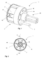
- FIG. 1 and 2 show schematically a perspective view of a contact unit 1 and a plan view of the contact unit 1, comprising a contact holder 2 and a contact inserted therein 3.
- the illustrated contact unit 1 are regularly distributed over the circumference of the contact unit 1 seven contacts 3 can be used , however, embodiments are also conceivable which have a deviating arrangement and / or number of contacts 3. For example, fifteen receptacles are provided for contacts in a 15-pole embodiment, not shown. The number and / or arrangement of contacts is determined for example for certain plugs and sockets by appropriate ISO standards or DIN standards.
- the illustrated contact unit 1 is suitable, for example, for use in a socket according to DIN ISO 7638. However, the invention is not limited to contact units for such sockets.
- the contact holder 2 comprises a protective part 4 and a base part not visible in FIG. 1, which is inserted into the protective part 4.
- the base part and the protective part 4 have in the illustrated embodiment complementary locking lugs 50 and recesses 40, via which they can be locked together.
- the protective part 4 shown further has projections 42, by means of which the contact holder 2 can be positioned in a housing, not shown, in a specific orientation.
- the protective part 4 is formed on its front side with a sealing cap 44, by means of which a connection region of the contacts 3, not visible in FIG. 1, can be protected against moisture and / or dirt.
- the sealing cap 44 has passages 45 for the contacts 3, wherein the sealing cap 44 bears flush against the contact 3.
- the contact holder 2 shown is preferably used as already described in the housing of a socket according to DIN ISO 7638.
- the contact holder 2 has an ejection unit 46.
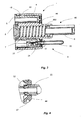
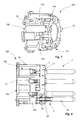
- FIG. 3 shows a sectional view of the contact unit 1 along the sectional plane III-III according to FIG. 2.
- a housing 460 of the ejection unit 46 is formed on the protective part 4.
- the ejection unit 46 comprises a rod element 6, which is acted upon by a spring 7 and is movable in the axial direction relative to the contact unit 1.
- the rod member 6 and the spring 7 are inserted into the housing 460 of the ejection unit and secured by an end cap 8.
- the illustrated contact 3 is in two parts with a contact piece 30 and a connector 32 ausformt, which are crimped together in the illustrated embodiment.
- the connecting piece 32 is formed in the illustrated embodiment as a stamped part and has a stop 34 which is formed by bending of the stamped part.
- a conductor can be fastened in the usual way. The attachment of the conductor can advantageously take place before insertion of the contact 3 into an opening 52 of the base part 5 or by removal from the opening 52. This allows easy handling.
- the illustrated contact piece 30 can be manufactured, for example, by deep drawing and is shaped as a hollow body.
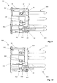
- FIG. 4 is an enlarged view of the connecting portion IV of the contact piece 30 with the connector 32 shown in FIG. 3. As seen in Fig. 4, the connector 32 is inserted for connection with the contact piece 30 in this and the contact piece 30 for a connection bent into corresponding recesses on the connector.
- the sealing cap 44 is preferably connected in the manufacture of the protective part by injection molding with this. As can be seen in FIGS. 3 and 4, a connection of the sealing cap 44 to the protective part 4 is improved by lugs 47.
- Fig. 5 is a perspective view of the base member 5 with a contact 3 inserted.
- the base member 5 has longitudinally extending openings 52 into which contacts 3 are insertable.
- the contacts are 3 for this radially into the openings 52 latched.
- the openings 52 have clamping region 53 with an upper and a lower stop surface 54, 55 for the axial positioning of the contact 3.
- the illustrated contact 3 has for this purpose a corresponding tapered region between the contact piece 30 and the stop 34.
- the upper abutment surface 54 is adjoined by an edge 56, which improves a guidance of the contact in the opening 52.
- webs 57 are provided.
- the base part 5 is further formed with locking lugs 50 already described for latching with the protective part shown in Fig. 6.
- Fig. 6 is a perspective view of the protective part 4 without inserted base part.
- the illustrated protective part 4 is formed as a hollow cylinder with a closed front side 4A.
- the housing 460 of the ejection unit 46 already described extends.
- the protective part 4 does not have a closed front side 4A.
- On the front side 4A a sealing cap 44 is arranged, which seals the interior of the protective part 4.
- the sealing cap 44 and the front side 4A of the protective part 4 are formed with passages 45, through which the contacts 3 shown in FIG. 5, for example, can be carried out.
- the protective part 4 can thus be inserted from a rear side 4B of the protective part 4 into the latter, wherein the latching noses 50 of the base part 5 engage in the recesses 40 of the protective part 4.
- the scope of the illustrated protective part 4 has a peripheral edge 48, by which a sealing surface of the protective part 4 is limited. About the sealing surface takes place in the illustrated embodiment, the sealing of the protective part 4 to a housing, not shown.
- Fig. 7 is a perspective view of a base part 105 according to a second embodiment of the invention.
- the base part 105 essentially corresponds to the base part 5 according to FIGS. 1 to 6, and identical reference symbols are used for the same components.
- the base part 105 is, for example, with that shown in Fig. 3 Protective part 4 by means of the locking lugs 50 latched.
- the base part 105 has recesses 152, wherein the recesses 152 are designed as grooves arranged on the outer circumference and having a clamping region 53 in the axial direction. In contrast to the embodiment according to FIGS. 1 to 5, however, no webs 57 are present.
- recesses 152 By such recesses 152 a simple engagement of the male contacts 3 in the base part 105 by moving the contacts 3 in the radial direction is possible. In order for a handling of a corresponding contact holder is particularly simple and mechanical stress on the contacts and / or on the associated conductor during insertion can be minimized.
- the recesses 152 are connected to chambers 153, the function of which will be explained below with reference to FIG. 9.
- the base part 105 has a circumferential groove or step 154, on which a locking ring, not shown in FIG. 7, can be latched.
- FIG. 8 shows the base part 105 according to FIG. 7 in a partially cut-free representation, into which contacts 3 according to FIGS. 3 and 5 are inserted, each with a contact piece 30 and a connecting piece 32, four contacts 3 being visible in FIG ,
- a securing ring 9 is latched onto the step 154 of the base part 105 shown in FIG. 7 as secondary locking.
- the circlip 9 rests with its inner circumference on the contacts 3 and prevents skewing of the contacts 3.
- the circlip 9 shown has lugs 90 which engage in the contacts 3.
- the circlip 9 also ensures that all contacts 3 are properly latched in the recesses 152, since without a sufficient locking of the contacts 3 in the recesses 152 of the retaining ring 9 is not attached to the base member 105.
- the retaining ring 9 further has at its periphery a plurality, in the illustrated embodiment, four, axially extending latching arms 92 for latching with the base part 105 on.
- FIG. 9 shows the base part 105 according to FIG. 7 in a partially cutaway view, into which contacts 203 according to another exemplary embodiment are inserted, wherein in FIG. 9 four contacts 203 are visible.
- the contacts 203 are integrally formed, for example, as a rotating part.
- the contacts 203 grooves 231 in the circumferential direction.
- the lugs 90 of the attached securing ring 9 also engage in the grooves 231.
- At connection ends of the contacts 203 bores 232 are provided, in which conductors not shown by means of screws 236 are fastened.
- the screws 236 can be arranged in the chambers 153.
- FIG. 10 shows a structural unit similar to FIG. 9 with a base part 105 and contacts 203 latched therein.
- a securing ring 309 which essentially corresponds to the securing ring 9 according to FIG. 9 and also essentially fulfills the same functions is latched to the base part 105.
- the securing ring 309 has no noses and no slots in the axial direction.
- Fig. 11 shows a perspective, partially exploded view of the assembly of FIG. 10 with the locking ring 309 and inserted contacts 203.
- the locking ring 309 at its periphery a plurality, in the illustrated embodiment three, in Axially extending latching arms 92, via which the locking ring 309 can be latched to the base part 105.
- contact surfaces 93 for the contacts 3, 203 are provided on the inner circumference of the illustrated securing ring 309.
Abstract
Description
Die Erfindung betrifft einen Kontakthalter für einen Stecker oder eine Steckdose, insbesondere für einen Stecker oder eine Steckdose für eine Verbindung zwischen einem Motorwagen und einem Anhängerfahrzeug, umfassend ein Basisteil, das mindestens eine sich in Längsrichtung erstreckende Öffnung aufweist, in welche ein Kontakt einsetzbar ist. Die Erfindung betrifft weiter eine Kontakteinheit, umfassend einen Kontakthalter und mindestens einen Kontakt, sowie einen Kontakt oder mehrere Kontakte für einen Kontakthalter.The invention relates to a contact holder for a plug or a socket, in particular for a plug or a socket for a connection between a towing vehicle and a trailer, comprising a base part having at least one longitudinally extending opening into which a contact can be inserted. The invention further relates to a contact unit, comprising a contact holder and at least one contact, as well as a contact or a plurality of contacts for a contact holder.
Es ist allgemein bekannt, Stecker oder Steckdosen für einen elektrischen Anschluss von Anhängerfahrzeugen mit einem Kontakthalter auszuformen, welcher eine Vielzahl an Aufnahmen aufweist, in welche Kontakte wie Steckerstifte oder Buchsen einsetzbar sind. Die Kontakthalter werden entweder einteilig mit einem Gehäuse ausgeformt oder als separates Bauteil, das nach einem Bestücken mit Kontakten in ein Gehäuse einsetzbar ist. Die Anzahl und/oder Lage der Kontakte ist durch ISO-Standards und/oder DIN-Normen definiert.It is well known to form plugs or sockets for an electrical connection of trailer vehicles with a contact holder, which has a variety of recordings, in which contacts such as pins or sockets can be used. The contact holders are either formed integrally with a housing or as a separate component that can be used after a population with contacts in a housing. The number and / or location of the contacts is defined by ISO standards and / or DIN standards.
Aus der
Es ist Aufgabe der vorliegenden Erfindung, einen Kontakthalter zu schaffen, durch welchen die Kontakte besser vor Verunreinigungen schützbar sind. Es ist weiter Aufgabe der vorliegenden Erfindung, eine Kontakteinheit zu schaffen, bei welcher ein eingesetzter Kontakt vor Verunreinigungen geschützt wird, sowie einen Kontakt für einen Kontakthalter, welcher einfach zu fertigen ist.It is an object of the present invention to provide a contact holder, through which the contacts are better protected from contamination. It is a further object of the present invention to provide a contact unit in which an inserted contact is protected from contamination, and a contact for a contact holder, which is easy to manufacture.
Diese Aufgabe wird gelöst durch einen Kontakthalter für einen Stecker oder eine Steckdose, umfassend ein Basisteil, das mindestens eine, sich in Längsrichtung erstreckende Öffnung aufweist, in welche mindestens ein Kontakt einsetzbar ist, wobei das Basisteil mindestens teilweise in ein Schutzteil einsetzbar ist, so dass der in das Basisteil eingesetzte Kontakt mindestens in Radialrichtung durch das Schutzteil geschützt ist und für einen Gebrauch zugänglich ist, und das Schutzteil mit eingesetztem Basisteil in ein Gehäuse des Steckers oder der Steckdose einsetzbar ist. Durch das Schutzteil wird erreicht, dass die in die Öffnungen eingesetzten Kontakte zumindest in Radialrichtung besser geschützt sind. Durch das Schutzteil wird weiter auch eine radiale Lagerung der Kontakte verbessert. Das Schutzteil ist beispielsweise als Hohlzylinder, als Ring oder als Kappe ausgeformt, in welchen ein zugehöriges Basisteil einsetzbar ist.This object is achieved by a contact holder for a plug or a socket, comprising a base part having at least one longitudinally extending opening into which at least one contact can be inserted, wherein the base part is at least partially insertable into a protective part, so that the contact inserted in the base part is protected at least in the radial direction by the protective part and is accessible for use, and the protective part with inserted base part can be inserted into a housing of the plug or socket. By the protective part ensures that the contacts inserted into the openings are better protected at least in the radial direction. By the protective part, a radial bearing of the contacts is further improved. The protective part is formed for example as a hollow cylinder, as a ring or as a cap, in which an associated base part can be used.
In Weiterbildung der Erfindung weist das Schutzteil an einer Frontseite eine Dichtkappe auf. Durch die Dichtkappe wird ein Eindringen von Schmutzpartikeln und/oder Feuchtigkeit in einen Anschlussbereich der Kontakte, an welchen diese mit entsprechenden Leitern verbunden sind, verhindert oder zumindest reduziert wird. Als Materialien für die Dichtkappe sind dabei gewöhnliche Dichtmaterialien einsetzbar, welche vorzugsweise elastisch sind.In a development of the invention, the protective part has a sealing cap on a front side. Through the sealing cap is an intrusion of dirt particles and / or moisture in a connection area of the Contacts, where they are connected to corresponding conductors, prevents or at least reduced. As materials for the sealing cap ordinary sealing materials are used, which are preferably elastic.
In Weiterbildung der Erfindung ist die Dichtkappe als Einsatzteil für einen Spritzguss ausgeformt. Die Dichtkappe ist somit während des Formens des Schutzteils als Spritzgussteil auf einfache Art und Weise mit diesem verbindbar. Die Verbindung zwischen der Dichtkappe und dem Schutzteil ist gemäß einer Ausführungsform durch Nasen und ähnliche Ausformungen gestärkt. In einer anderen Ausführungsform wird die Dichtkappe mit dem ausgeformten Schutzteil verrastet.In a further development of the invention, the sealing cap is formed as an insert for injection molding. The sealing cap is thus connected during the molding of the protective part as an injection molded part in a simple manner with this. The connection between the sealing cap and the protective part is strengthened in one embodiment by noses and similar formations. In another embodiment, the sealing cap is locked with the molded protective part.
Gemäß einer vorteilhaften Ausführungsform weist die Dichtkappe mindestens einen Durchgang für den mindestens einen Kontakt auf, an welchen ein eingesetzter Kontakt bündig anliegt. Wenn die Dichtkappe aus elastischem Material ausgeformt ist, so kann ein Durchmesser des Durchgangs im Wesentlichen gleich groß wie oder geringfügig kleiner als ein Durchmesser des aufzunehmenden Kontakts gewählt werden. Beim Einsetzen wird die Dichtkappe im Bereich des Durchgangs leicht verformt und liegt so bündig an einen eingesetzten Kontakt an.According to an advantageous embodiment, the sealing cap has at least one passage for the at least one contact against which an inserted contact rests flush. When the sealing cap is formed of elastic material, a diameter of the passage may be selected substantially equal to or slightly smaller than a diameter of the male contact. When inserting, the sealing cap is slightly deformed in the region of the passage and thus lies flush against an inserted contact.
In einer weiteren Ausführungsform ist das Schutzteil mit einer Auswurfeinheit ausgebildet, welche ein durch eine Feder beaufschlagtes und in Axialrichtung relativ zu dem Kontakthalter bewegbares Stabelement umfasst. Derartige Auswurfeinheiten sind allgemein bekannt. Sie sind vorzugsweise an einer Steckdose vorgesehen, um durch die vorgespannte Feder eine Entnahme eines eingesetzten Steckers zu erleichtern. Durch die Ausbildung der Auswurfeinheit an dem Schutzteil kann die Form des Basisteils vereinfacht werden, so dass eine Herstellung des Basisteils verbessert wird. Ein Gehäuse der Auswurfeinheit ist in einer Ausführungsform einteilig mit dem Schutzteil ausgeformt, beispielsweise als Spritzgussteil. In einer anderen Ausführungsform ist die Auswurfeinheit als separates Bauteil ausgeformt, welches mit einem Körper des Schutzteils verrastet, verklebt, verschraubt, vernietet und/oder auf andere Art und Weise verbunden wird.In a further embodiment, the protective part is formed with an ejection unit which comprises a rod element acted upon by a spring and movable in the axial direction relative to the contact holder. Such ejection units are well known. They are preferably provided at a socket to facilitate removal of an inserted plug by the preloaded spring. By forming the ejection unit on the protective part, the shape of the base part can be simplified, so that production of the base part is improved. A housing of the ejection unit is integrally formed in one embodiment with the protective part, for example as Injection molded part. In another embodiment, the ejection unit is formed as a separate component, which is locked to a body of the protective part, glued, screwed, riveted and / or connected in other ways.
In Weiterbildung der Erfindung sind das Basisteil und das Schutzteil miteinander verrastbar. Durch die Verrastung ist eine einfache, werkzeuglos lösbare Verbindung des Basisteils mit dem Schutzteil möglich. Dadurch sind beispielsweise in das Basisteil eingesetzte Kontakte für eine Wartung und/oder aufgrund eines Defekts jederzeit durch Entfernung des Schutzteils leicht zugänglich.In a further development of the invention, the base part and the protective part are locked together. By locking a simple, tool-free detachable connection of the base part with the protective part is possible. As a result, for example, contacts used in the base part for maintenance and / or due to a defect are readily accessible at any time by removal of the protective part.
In einer weiteren Ausführungsform weist das Schutzteil an seinem äußeren Umfang mindestens einen Vorsprung und/oder eine Ausnehmung auf, durch welche es in dem Gehäuse des Steckers oder der Steckdose positionierbar ist. Der eingesetzte Kontakthalter ist beispielsweise durch eine Abschlusskappe des Gehäuses und/oder durch Verdrehung, beispielsweise durch ein Gewinde oder einen Bajonettverschluss, in dem Gehäuse fixierbar.In a further embodiment, the protective part has on its outer periphery at least one projection and / or a recess, by means of which it can be positioned in the housing of the plug or of the socket. The inserted contact holder can be fixed in the housing, for example, by a closure cap of the housing and / or by rotation, for example by a thread or a bayonet closure.
In einer weiteren Ausführungsform weist die Öffnung eine obere und eine untere Anschlagsfläche zur axialen Positionierung eines Kontakts mit einem verjüngten Bereich auf. Dadurch ist eine sichere axiale Positionierung der Kontakte in dem Basisteil und damit in dem Stecker oder der Steckdose möglich.In another embodiment, the opening has upper and lower stop surfaces for axially positioning a contact with a tapered region. As a result, a secure axial positioning of the contacts in the base part and thus in the plug or the socket is possible.
Bevorzugt sind die Kontakte radial in die entsprechenden Öffnungen einrastbar. Dadurch ist eine besonders leichte Montage und/oder Demontage der Kontakte möglich.Preferably, the contacts are radially engageable in the corresponding openings. As a result, a particularly easy assembly and / or disassembly of the contacts is possible.
Die Aufgabe wird weiter gelöst durch eine Kontakteinheit, umfassend einen oben beschriebenen Kontakthalter sowie mindestens einen eingesetzten Kontakt.The object is further achieved by a contact unit comprising a contact holder described above and at least one inserted contact.
Weiter wird die Aufgabe gelöst durch einen Kontakt für einen oben beschriebenen Kontakthalter, wobei der Kontakt zweiteilig ausgeformt ist, umfassend ein Kontaktstück und ein Anschlussstück. Das Kontaktstück dient der Kontaktierung eines korrespondierenden zweiten Kontakts. Es ist beispielsweise als Kontaktstift oder als Buchse ausgeformt. Das Anschlussstück dient einer Verbindung zu einem Leiter. Das Anschlussstück weist beispielsweise Elemente für eine Crimp-Verbindung mit einem Leiter auf. Ein derartiger zweiteiliger Kontakt ist besonders einfach fertigbar, wobei jeweilige Anforderungen an die beiden Stücke durch die zweiteilige Ausformung besonders gut berücksichtigbar sind. Ein derartiger zweiteiliger Kontakt ist auch für den Einsatz in anderen Kontakthaltern vorteilhaft.Further, the object is achieved by a contact for a contact holder described above, wherein the contact is formed in two parts, comprising a contact piece and a connection piece. The contact piece is used to make contact with a corresponding second contact. It is formed, for example, as a contact pin or as a socket. The connection piece is used to connect to a conductor. The connector has, for example, elements for a crimp connection with a conductor. Such a two-part contact is particularly easy to manufacture, with particular demands on the two pieces by the two-part design are particularly well considered. Such a two-part contact is also advantageous for use in other contact holders.
In einer weiteren Ausführungsform ist das Kontaktstück des Kontakts als Tiefziehteil ausgeformt. Die Ausformung als Tiefziehteil ermöglicht eine kostengünstige Herstellung mit einer hohen Genauigkeit.In a further embodiment, the contact piece of the contact is formed as a deep-drawn part. The formation as a deep-drawn part allows cost-effective production with high accuracy.
In einer weiteren Ausführungsform ist das Anschlussstück als Stanzteil ausgebildet. Dadurch ist eine besonders kostengünstige Fertigung des Anschlussstückes möglich. Zur Verbindung des Kontaktstücks mit dem Anschlussstück ist beispielsweise das Anschlussstück in eine Öffnung an einem rückseitigen Ende eines tiefgezogenen oder gedrehten Kontaktstücks einsetzbar und mit diesem beispielsweise durch Verformung verbindbar. Daneben ist es auch möglich, die beiden Stücke miteinander zu verkleben, zu verlöten oder auf andere Weise zu verbinden.In a further embodiment, the connecting piece is formed as a stamped part. As a result, a particularly cost-effective production of the connection piece is possible. For connection of the contact piece with the connection piece, for example, the connection piece can be inserted into an opening at a rear end of a deep-drawn or turned contact piece and can be connected thereto, for example by deformation. In addition, it is also possible to glue the two pieces together, to solder or otherwise connect.
In Weiterbildung der Erfindung weist das Anschlussstück einen Anschlag auf, der durch Biegung des Stanzteils geformt ist. Dadurch ist kostengünstig ein Kontakt mit einem verjüngten Bereich herstellbar, welcher in einer entsprechenden Öffnung des Kontakthalters axial gesichert positionierbar ist.In a further development of the invention, the connecting piece has a stop which is formed by bending the stamped part. This is inexpensive contact with a tapered region produced, which is axially secured positionable in a corresponding opening of the contact holder.
Weitere Vorteile der Erfindung ergeben sich aus der nachfolgenden Beschreibung von Ausführungsbeispielen, die in den Zeichnungen dargestellt sind. Für gleiche Bauteile werden dabei einheitliche Bezugszeichen verwendet. Merkmale, welche für eine Ausführungsform gezeigt sind, können dabei mit Merkmalen aus anderen Ausführungsformen kombiniert werden, um so weitere Ausführungsformen zu erhalten. Sämtliche in den Figuren dargestellten Merkmale können sowohl für sich, als auch in Kombination erfindungswesentlich sein.Further advantages of the invention will become apparent from the following description of exemplary embodiments, which are illustrated in the drawings. Uniform reference numbers are used for the same components. Features shown for one embodiment may be combined with features of other embodiments to provide further embodiments. All features shown in the figures can be essential to the invention both individually and in combination.
In den Zeichnungen zeigen:
- Fig. 1
- eine perspektivische Darstellung einer Kontakteinheit, umfassend einen Kontakthalter und einen eingesetzten Kontakt;
- Fig. 2
- eine Draufsicht auf die Kontakteinheit gemäß Fig. 1;
- Fig. 3
- einen Schnitt durch die Kontakteinheit gemäß Fig. 2 entlang der Ebene III-III;
- Fig. 4
- eine vergrößerte Darstellung des Bereichs IV gemäß Fig. 3;
- Fig. 5
- eine perspektivische Darstellung eines Basisteils eines erfindungsgemäßen Kontakthalters;
- Fig. 6
- eine perspektivische Darstellung eines Schutzteils eines erfindungsgemäßen Kontakthalters;
- Fig. 7
- eine perspektivische Darstellung eines Basisteils eines Kontakthalters gemäß einem zweiten Ausführungsbeispiel der Erfindung;
- Fig. 8
- eine teilweise freigeschnittene Seitenansicht des Basisteils gemäß Fig. 7 mit eingesetzten Kontakten;
- Fig. 9
- eine teilweise freigeschnittene Seitenansicht des Basisteils gemäß Fig. 7 mit eingesetzten Kontakten gemäß einer anderen Ausführungsform;
- Fig. 10
- eine teilweise freigeschnittene Seitenansicht des Basisteils gemäß Fig. 7 mit eingesetzten Kontakten und einem Sicherungsring gemäß einer weiteren Ausführungsform und
- Fig. 11
- eine perspektivische Explosionsdarstellung des Basisteils gemäß Fig. 10.
- Fig. 1
- a perspective view of a contact unit, comprising a contact holder and a contact inserted;
- Fig. 2
- a plan view of the contact unit of FIG. 1;
- Fig. 3
- a section through the contact unit of Figure 2 along the plane III-III.
- Fig. 4
- an enlarged view of the area IV of FIG. 3;
- Fig. 5
- a perspective view of a base part of a contact holder according to the invention;
- Fig. 6
- a perspective view of a protective part of a contact holder according to the invention;
- Fig. 7
- a perspective view of a base part of a contact holder according to a second embodiment of the invention;
- Fig. 8
- a partially cutaway side view of the base part of Figure 7 with inserted contacts ..;
- Fig. 9
- a partially cutaway side view of the base part of Figure 7 with inserted contacts according to another embodiment.
- Fig. 10
- a partially cutaway side view of the base part of FIG. 7 with inserted contacts and a locking ring according to another embodiment and
- Fig. 11
- an exploded perspective view of the base part of FIG .. 10
Fig. 1 und 2 zeigen schematisch eine perspektivische Darstellung einer Kontakteinheit 1 und eine Draufsicht auf die Kontakteinheit 1, umfassend einen Kontakthalter 2 und eine darin eingesetzten Kontakt 3. In die dargestellte Kontakteinheit 1 sind über den Umfang der Kontakteinheit 1 regelmäßig verteilt sieben Kontakte 3 einsetzbar. Es sind jedoch auch Ausführungsformen denkbar, welche eine davon abweichende Anordnung und/oder Anzahl an Kontakten 3 aufweisen. Beispielsweise sind in einer nicht dargestellten 15-poligen Ausführungsform fünfzehn Aufnahmen für Kontakte vorgesehen. Die Anzahl und/oder Anordnung an Kontakten ist beispielsweise für bestimmte Stecker und Steckdosen durch entsprechende ISO-Standards oder DIN-Normen festgelegt. Die dargestellte Kontakteinheit 1 ist beispielsweise für den Einsatz in einer Steckdose nach DIN ISO 7638 geeignet. Die Erfindung ist jedoch nicht auf Kontakteinheiten für derartige Steckdosen begrenzt.1 and 2 show schematically a perspective view of a
Der Kontakthalter 2 umfasst ein Schutzteil 4 und ein in Fig. 1 nicht sichtbares Basisteil, das in das Schutzteil 4 eingesetzt ist. Das Basisteil und das Schutzteil 4 weisen in der dargestellten Ausführungsform komplementäre Rastnasen 50 und Ausnehmungen 40 auf, über welche sie miteinander verrastbar sind.The
Das dargestellte Schutzteil 4 weist weiter Vorsprünge 42 auf, durch welche der Kontakthalter 2 in einem nicht dargestellten Gehäuse in einer bestimmten Ausrichtung positionierbar ist.The
Das Schutzteil 4 ist an seiner Frontseite mit einer Dichtkappe 44 ausgebildet, durch welche ein in Fig. 1 nicht sichtbarer Anschlussbereich der Kontakte 3 vor Feuchtigkeit und/oder Schmutz schützbar ist. Die Dichtkappe 44 weist Durchgänge 45 für die Kontakte 3 auf, wobei die Dichtkappe 44 an den Kontakt 3 bündig anliegt.The
Der dargestellte Kontakthalter 2 ist wie bereits beschrieben vorzugsweise in das Gehäuse einer Steckdose nach DIN ISO 7638 einsetzbar. Für eine vereinfachte Entfernung eines in die Steckdose eingesetzten Steckers weist der Kontakthalter 2 eine Auswurfeinheit 46 auf.The
Fig. 3 zeigt eine Schnittansicht der Kontakteinheit 1 entlang der Schnittebene III-III gemäß Fig. 2. Wie in Fig. 3 ersichtlich, ist in der dargestellten Ausführungsform ein Gehäuse 460 der Auswurfeinheit 46 an dem Schutzteil 4 ausgeformt. Die Auswurfeinheit 46 umfasst ein Stabelement 6, welches durch eine Feder 7 beaufschlagt ist und in Axialrichtung relativ zu der Kontakteinheit 1 bewegbar ist. Das Stabelement 6 und die Feder 7 sind in das Gehäuse 460 der Auswurfeinheit eingesetzt und durch eine Abschlusskappe 8 gesichert.3 shows a sectional view of the
Wie in Fig. 3 weiter ersichtlich, ist der dargestellte Kontakt 3 zweiteilig mit einem Kontaktstück 30 und einem Anschlussstück 32 ausformt, welche in der dargestellten Ausführungsform miteinander vercrimpt sind. Das Anschlussstück 32 ist in der dargestellten Ausführungsform als Stanzteil ausgeformt und weist einen Anschlag 34 auf, der durch Biegung des Stanzteils geformt ist. An dem Anschlussstück 32 ist ein nicht dargestellter Leiter auf übliche Weise befestigbar. Die Befestigung des Leiters kann vorteilhaft vor einem Einsetzen des Kontakts 3 in eine Öffnung 52 des Basisteils 5 oder durch eine Entnahme aus der Öffnung 52 erfolgen. Dadurch ist eine einfache Handhabung möglich. Das dargestellte Kontaktstück 30 ist beispielsweise durch Tiefziehen fertigbar und ist als Hohlkörper ausgeformt.As further shown in Fig. 3, the illustrated
Fig. 4 ist eine vergrößerte Darstellung des Verbindungsbereichs IV des Kontaktstücks 30 mit dem Anschlussstück 32 gemäß Fig. 3. Wie in Fig. 4 erkennbar, wird das Anschlussstück 32 für eine Verbindung mit dem Kontaktstück 30 in dieses eingesetzt und das Kontaktstück 30 für eine Verbindung in entsprechende Ausnehmungen an dem Anschlussstück umgebogen.4 is an enlarged view of the connecting portion IV of the
Die Dichtkappe 44 wird vorzugsweise bei der Fertigung des Schutzteils durch Spritzguss mit diesem verbunden. Wie in Fig. 3 und 4 erkennbar, ist eine Verbindung der Dichtkappe 44 mit dem Schutzteil 4 durch Nasen 47 verbessert.The sealing
Fig. 5 ist eine perspektivische Darstellung des Basisteils 5 mit einem eingesetzten Kontakt 3. Wie in Fig. 5 ersichtlich, weist das Basisteil 5 sich in Längsrichtung erstreckende Öffnungen 52 auf, in welche Kontakte 3 einsetzbar sind. Die Kontakte sind 3 hierfür radial in die Öffnungen 52 einrastbar. Die Öffnungen 52 weisen Klemmbereich 53 mit einer oberen und einer unteren Anschlagsfläche 54, 55 zur axialen Positionierung des Kontakts 3 auf. Der dargestellte Kontakt 3 weist zu diesem Zweck einen entsprechenden verjüngten Bereich zwischen dem Kontaktstück 30 und dem Anschlag 34 auf. An die obere Anschlagsfläche 54 schließt ein Rand 56 an, welcher eine Führung des Kontakts in der Öffnung 52 verbessert. An einem hinteren Ende des Basisteils 5 sind Stege 57 vorgesehen. Das Basisteil 5 ist weiter mit bereits beschriebenen Rastnasen 50 für eine Verrastung mit dem in Fig. 6 dargestellten Schutzteil ausgeformt.Fig. 5 is a perspective view of the
Fig. 6 ist eine perspektivische Darstellung des Schutzteils 4 ohne eingesetztes Basisteil. Das dargestellte Schutzteil 4 ist als Hohlzylinder mit einer geschlossenen Frontseite 4A ausgeformt. An der Frontseite 4A erstreckt sich das Gehäuse 460 der bereits beschriebenen Auswurfeinheit 46. Bei einer Ausformung des Schutzteils 4 ohne Auswurfeinheit 46 ist es denkbar, dass das Schutzteil 4 keine geschlossene Frontseite 4A aufweist. An der Frontseite 4A ist eine Dichtkappe 44 angeordnet, welche den Innenraum des Schutzteils 4 abdichtet. Die Dichtkappe 44 und die Frontseite 4A des Schutzteils 4 sind mit Durchgängen 45 ausgeformt, durch welche die beispielsweise in Fig. 5 dargestellten Kontakte 3 durchführbar sind. Das in Fig. 5 dargestellte Basisteil 5 kann so von einer Rückseite 4B des Schutzteils 4 in dieses eingesetzt werden, wobei die Rastnasen 50 des Basisteils 5 in die Ausnehmungen 40 des Schutzteils 4 einrasten. Aus fertigungstechnischen gründen weist der Umfang des dargestellten Schutzteils 4 eine Umlaufkante 48 auf, durch welche eine Dichtfläche des Schutzteils 4 begrenzt ist. Über die Dichtfläche erfolgt in der dargestellten Ausführungsform die Abdichtung des Schutzteils 4 zu einem nicht dargestellten Gehäuse.Fig. 6 is a perspective view of the
Fig. 7 ist eine perspektivische Darstellung eines Basisteils 105 gemäß einem zweiten Ausführungsbeispiel der Erfindung. Das Basisteil 105 entspricht im Wesentlichen dem Basisteil 5 gemäß den Figuren 1 bis 6 und für gleiche Bauteile werden einheitliche Bezugszeichen verwendet. Das Basisteil 105 ist beispielsweise mit dem in Fig. 3 dargestellten Schutzteil 4 mittels der Rastnasen 50 verrastbar. Zur Aufnahme von in Fig. 7 nicht dargestellten Kontakten, beispielsweise Kontakten 3 gemäß Fig. 3 und 5, weist das Basisteil 105 Ausnehmungen 152 auf, wobei die Ausnehmungen 152 als am Außenumfang angeordnete, in Axialrichtung verlaufende Nuten mit einem Klemmbereich 53 gestaltet sind. Im Unterschied zu der Ausführungsform gemäß Fig. 1 bis 5 sind jedoch keine Stege 57 vorhanden. Durch derartige Ausnehmungen 152 ist ein einfaches Einrasten der aufzunehmenden Kontakte 3 in das Basisteil 105 durch Bewegen der Kontakte 3 in radialer Richtung möglich. Damit ist eine Handhabung eines entsprechenden Kontakthalters besonders einfach und eine mechanische Belastung an den Kontakten und/oder an den damit verbundenen Leiter beim Einsetzen kann minimiert werden. Die Ausnehmungen 152 sind mit Kammern 153 verbunden, deren Funktion weiter unten in Bezug auf Fig. 9 erläutert wird. Das Basisteil 105 weist eine Umfangsnut oder Stufe 154 auf, an welcher ein in Fig. 7 nicht dargestellter Sicherungsring verrastbar ist.Fig. 7 is a perspective view of a
Fig. 8 zeigt das Basisteil 105 gemäß Fig. 7 in einer teilweise frei geschnittenen Darstellung, in das Kontakte 3 gemäß Fig. 3 und 5 mit jeweils einem Kontaktstück 30 und einem Anschlussstück 32 eingesetzt sind, wobei in Fig. 8 vier Kontakte 3 sichtbar sind. An den Anschlussstücken 32 der Kontakte 3 sind nicht dargestellte Leiter mittels der Rastmittel des Anschlussstücks 32 befestigbar. Für eine zusätzliche Sicherung der Kontakte 3 in radialer Richtung ist auf die in Fig. 7 dargestellte Stufe 154 des Basisteils 105 ein Sicherungsring 9 als Sekundärverriegelung verrastet. Der Sicherungsring 9 liegt mit seinem Innenumfang an den Kontakten 3 an und verhindert ein Schiefstellen der Kontakte 3. Der dargestellte Sicherungsring 9 weist Nasen 90 auf, welche in die Kontakte 3 greifen. Zum sicheren Eeingreifen weist der dargestellte Sicherungsring 9 in Axialrichtung Schlitze 91 auf, durch die der Sicherungsring 9 zum Aufbringen einer Spannkraft in Radialrichtung federnd gestaltet ist. Durch den Sicherungsring 9 wird auch sichergestellt, dass alle Kontakte 3 richtig in den Ausnehmungen 152 verrastet sind, da ohne eine ausreichende Verrastung der Kontakte 3 in den Ausnehmungen 152 der Sicherungsring 9 nicht an dem Basisteil 105 anbringbar ist. Der Sicherungsring 9 weist weiter an seinem Umfang eine Vielzahl, in der dargestellten Ausführungsform vier, sich in Axialrichtung erstreckenden Rastarme 92 für eine Verrastung mit dem Basisteil 105 auf.FIG. 8 shows the
Fig. 9 zeigt das Basisteil 105 gemäß Fig. 7 in einer teilweise frei geschnittenen Darstellung, in das Kontakte 203 gemäß einem anderen Ausführungsbeispiel eingesetzt sind, wobei in Fig. 9 vier Kontakte 203 sichtbar sind. Die Kontakte 203 sind einteilig, beispielsweise als Drehteil ausgebildet. Zum Verrasten mit dem Basisteil 105 weisen die Kontakte 203 Nuten 231 in Umfangsrichtung auf. Die Nasen 90 des angebrachten Sicherungsrings 9 greifen ebenfalls in die Nuten 231 ein. An Anschlussenden der Kontakte 203 sind Bohrungen 232 vorgesehen, in welchen nicht dargestellte Leiter mittels Schrauben 236 befestigbar sind. Die Schrauben 236 können dabei in den Kammern 153 angeordnet werden.FIG. 9 shows the
Fig. 10 zeigt eine Baueinheit ähnlich Fig. 9 mit einem Basisteil 105 und darin verrasteten Kontakten 203. Mit dem Basisteil 105 ist ein Sicherungsring 309 verrastet, welcher im Wesentlichen dem Sicherungsring 9 gemäß Fig. 9 entspricht und auch im Wesentlichen die gleichen Funktionen erfüllt. Im Unterschied zu dem Sicherungsring 9 gemäß Fig. 9 weist der Sicherungsring 309 jedoch keine Nasen und keine Schlitze in Axialrichtung auf.FIG. 10 shows a structural unit similar to FIG. 9 with a
Fig. 11 zeigt eine perspektivische, teilweise explodierte Darstellung der Baueinheit gemäß Fig. 10 mit dem Sicherungsring 309 und eingesetzten Kontakten 203. Wie in Fig. 11 erkennbar, weist der Sicherungsring 309 an seinem Umfang eine Vielzahl, in der dargestellten Ausführungsform drei, sich in Axialrichtung erstreckenden Rastarme 92 auf, über welche der Sicherungsring 309 mit dem Basisteil 105 verrastbar ist. Wie in Fig. 11 weiter erkennbar ist, sind an dem Innenumfang des dargestellten Sicherungsrings 309 Anlageflächen 93 für die Kontakte 3, 203 vorgesehen.Fig. 11 shows a perspective, partially exploded view of the assembly of FIG. 10 with the
Die dargestellten Ausführungsformen sind lediglich beispielhaft. Merkmale, welche für eine Ausführungsform gezeigt sind, können mit Merkmalen aus anderen Ausführungsformen kombiniert werden, um so weitere Ausführungsformen zu erhalten.The illustrated embodiments are merely exemplary. Features shown for one embodiment may be combined with features of other embodiments to provide further embodiments.
Claims (15)
dadurch gekennzeichnet, dass
das Basisteil (5, 105) mindestens teilweise in das Schutzteil (4) einsetzbar ist, so dass der in das Basisteil (4) eingesetzte Kontakt (3, 203) mindestens in Radialrichtung durch das Schutzteil (4) geschützt ist und für einen Gebrauch zugänglich ist, und
das Schutzteil (4) mit eingesetztem Basisteil (5, 105) in ein Gehäuse des Steckers oder der Steckdose einsetzbar ist.A contact holder for a plug or a socket, in particular for a plug or a socket for a connection between a towing vehicle and a trailer, comprising a base part (5, 105) having at least one, longitudinally extending opening (52, 152), in which at least one contact (3, 203) can be inserted, and a protective part (4),
characterized in that
the base part (5, 105) is insertable at least partially into the protective part (4), so that the contact (3, 203) inserted in the base part (4) is protected at least in the radial direction by the protective part (4) and is accessible for use is and
the protective part (4) with inserted base part (5, 105) can be inserted into a housing of the plug or socket.
Applications Claiming Priority (1)
| Application Number | Priority Date | Filing Date | Title |
|---|---|---|---|
| DE102006025611A DE102006025611B3 (en) | 2006-05-24 | 2006-05-24 | Contact holder for a plug or a socket |
Publications (1)
| Publication Number | Publication Date |
|---|---|
| EP1860742A1 true EP1860742A1 (en) | 2007-11-28 |
Family
ID=38293226
Family Applications (1)
| Application Number | Title | Priority Date | Filing Date |
|---|---|---|---|
| EP20070009762 Withdrawn EP1860742A1 (en) | 2006-05-24 | 2007-05-16 | Contact holder for a plug or socket |
Country Status (2)
| Country | Link |
|---|---|
| EP (1) | EP1860742A1 (en) |
| DE (1) | DE102006025611B3 (en) |
Cited By (3)
| Publication number | Priority date | Publication date | Assignee | Title |
|---|---|---|---|---|
| DE102010030958A1 (en) * | 2010-07-05 | 2012-01-05 | Tyco Electronics Amp Gmbh | Arrangement, in particular plug and method of manufacture |
| CN104934745A (en) * | 2015-06-09 | 2015-09-23 | 西安航空制动科技有限公司 | Hollow rapid dismounting electric connector |
| CN107230860A (en) * | 2016-03-23 | 2017-10-03 | 泰连德国有限公司 | Power electrical contact device, replaceable power electrical contact module and power electric connector |
Families Citing this family (5)
| Publication number | Priority date | Publication date | Assignee | Title |
|---|---|---|---|---|
| DE102009021594B4 (en) * | 2009-04-09 | 2018-04-12 | Phoenix Contact Gmbh & Co. Kg | Electrical connector and electrical connector and method for connecting the remainder of a multicore cable to an electrical connector |
| DE102015213734A1 (en) | 2015-07-21 | 2017-01-26 | Itt Manufacturing Enterprises Llc | Connectors |
| DE102016105465A1 (en) | 2016-03-23 | 2017-09-28 | Escha GmbH & Co. KG | Connectors connected to twisted-pair cables |
| DE202019101871U1 (en) | 2019-04-02 | 2019-04-11 | Apparatebau Kirchheim-Teck Gmbh | Contact element with seal for a plug connection |
| DE102019208782B4 (en) * | 2019-06-06 | 2022-12-01 | Franz Binder Gmbh + Co. Elektrische Bauelemente Kg | Connector and release tool for disconnecting such a connector and corresponding method |
Citations (6)
| Publication number | Priority date | Publication date | Assignee | Title |
|---|---|---|---|---|
| US3836843A (en) * | 1971-10-26 | 1974-09-17 | E Yonce | Electric circuit tester connector for highway vehicles |
| US5066242A (en) * | 1990-10-15 | 1991-11-19 | Molex Incorporated | Environment-proof electrical connector assembly |
| EP0544630A2 (en) * | 1991-11-28 | 1993-06-02 | MENBER'S S.p.A. | An electrical connector, particularly for the connection of a towing vehicle and a towed vehicle with an antilock braking system |
| EP0610681A2 (en) * | 1993-02-12 | 1994-08-17 | MENBER'S S.p.A. | Contact holder for a socket or for a plug of an electrical connector |
| US5399110A (en) * | 1994-02-04 | 1995-03-21 | General Motors Corporation | Two piece male pin terminal |
| EP1617523A1 (en) * | 2004-07-16 | 2006-01-18 | IEMMEGI S.r.l. | Safety multipole electric connector construction |
Family Cites Families (3)
| Publication number | Priority date | Publication date | Assignee | Title |
|---|---|---|---|---|
| DE4006309A1 (en) * | 1990-03-01 | 1991-09-05 | Gebhard Dietrich | CONTACT CARRIER FOR A SOCKET OR A PLUG FOR A CONNECTOR FOR THE ELECTRICAL CONNECTION OF VEHICLE TRAILERS |
| DE69702436T2 (en) * | 1997-03-19 | 2001-01-25 | Air Lb International Luxembour | Connectors for a printed circuit board |
| DE20318251U1 (en) * | 2003-11-24 | 2004-03-18 | Coninvers Elektrotechnische Bauelemente Gmbh | In line electrical connector uses multi pin plugs that engage contacts in double socket bush within insulated housing |
-
2006
- 2006-05-24 DE DE102006025611A patent/DE102006025611B3/en active Active
-
2007
- 2007-05-16 EP EP20070009762 patent/EP1860742A1/en not_active Withdrawn
Patent Citations (6)
| Publication number | Priority date | Publication date | Assignee | Title |
|---|---|---|---|---|
| US3836843A (en) * | 1971-10-26 | 1974-09-17 | E Yonce | Electric circuit tester connector for highway vehicles |
| US5066242A (en) * | 1990-10-15 | 1991-11-19 | Molex Incorporated | Environment-proof electrical connector assembly |
| EP0544630A2 (en) * | 1991-11-28 | 1993-06-02 | MENBER'S S.p.A. | An electrical connector, particularly for the connection of a towing vehicle and a towed vehicle with an antilock braking system |
| EP0610681A2 (en) * | 1993-02-12 | 1994-08-17 | MENBER'S S.p.A. | Contact holder for a socket or for a plug of an electrical connector |
| US5399110A (en) * | 1994-02-04 | 1995-03-21 | General Motors Corporation | Two piece male pin terminal |
| EP1617523A1 (en) * | 2004-07-16 | 2006-01-18 | IEMMEGI S.r.l. | Safety multipole electric connector construction |
Cited By (7)
| Publication number | Priority date | Publication date | Assignee | Title |
|---|---|---|---|---|
| DE102010030958A1 (en) * | 2010-07-05 | 2012-01-05 | Tyco Electronics Amp Gmbh | Arrangement, in particular plug and method of manufacture |
| DE102010030958B4 (en) * | 2010-07-05 | 2012-02-02 | Tyco Electronics Amp Gmbh | Arrangement, in particular plug and method of manufacture |
| CN104934745A (en) * | 2015-06-09 | 2015-09-23 | 西安航空制动科技有限公司 | Hollow rapid dismounting electric connector |
| CN104934745B (en) * | 2015-06-09 | 2017-10-20 | 西安航空制动科技有限公司 | A kind of hollow fast quick-detach electric connector |
| CN107230860A (en) * | 2016-03-23 | 2017-10-03 | 泰连德国有限公司 | Power electrical contact device, replaceable power electrical contact module and power electric connector |
| EP3223371A3 (en) * | 2016-03-23 | 2017-11-29 | TE Connectivity Germany GmbH | Power-electric contact device; exchangeable power-electric contact module as well as power-electric connector |
| CN107230860B (en) * | 2016-03-23 | 2021-07-27 | 泰连德国有限公司 | Power electrical contact device, replaceable power electrical contact module and power electrical connector |
Also Published As
| Publication number | Publication date |
|---|---|
| DE102006025611B3 (en) | 2007-12-06 |
Similar Documents
| Publication | Publication Date | Title |
|---|---|---|
| DE102006016882B4 (en) | Connectors | |
| EP1851830B1 (en) | Connection system, in particular electrical connection system | |
| EP1275173B1 (en) | Plug-in connector with a bushing | |
| EP1860742A1 (en) | Contact holder for a plug or socket | |
| WO2006133925A1 (en) | Electrical plug-in connection, plug part, and socket part | |
| EP1182739A2 (en) | High current contact | |
| DE102006036297A1 (en) | Socket-type contact element and method of manufacturing a socket-like contact element | |
| EP2072844B1 (en) | Ball joint connector | |
| EP1641086B1 (en) | Coaxial connector | |
| EP1559605A2 (en) | Securing means for a container cap | |
| DE19848289C2 (en) | Locking device of a cap part | |
| DE102020115021A1 (en) | Device for connecting two tubular objects | |
| EP1672751B1 (en) | Lamp socket | |
| EP3143320A1 (en) | Connection unit for a coupling device, in particular a multiple coupling | |
| DE4306806B4 (en) | In a plate mountable electrical connector | |
| EP1720222B1 (en) | Electrical connector, particularly for airbag ignition systems | |
| DE102006027311B3 (en) | Plug connector contact holder, has housing into which contact holder is inserted by transverse movement and secured in housing against twist | |
| DE1765099B2 (en) | ELECTRIC CONNECTOR | |
| EP1467451A1 (en) | Coupling device for coaxial plug-in connector | |
| EP3859896A1 (en) | Contact socket for a contact carrier insert of a socket | |
| DE2337043C2 (en) | Electrical plug connection | |
| DE202011000750U1 (en) | Connector assembly for electrical conductors | |
| DE4407583C1 (en) | Electrical connecting part | |
| EP1462310B1 (en) | Steering column module | |
| EP2760085A1 (en) | Plug-in adapter module and manufacturing method for the same |
Legal Events
| Date | Code | Title | Description |
|---|---|---|---|
| PUAI | Public reference made under article 153(3) epc to a published international application that has entered the european phase |
Free format text: ORIGINAL CODE: 0009012 |
|
| AK | Designated contracting states |
Kind code of ref document: A1 Designated state(s): AT BE BG CH CY CZ DE DK EE ES FI FR GB GR HU IE IS IT LI LT LU LV MC MT NL PL PT RO SE SI SK TR |
|
| AX | Request for extension of the european patent |
Extension state: AL BA HR MK YU |
|
| 17P | Request for examination filed |
Effective date: 20080506 |
|
| AKX | Designation fees paid |
Designated state(s): AT BE BG CH CY CZ DE DK EE ES FI FR GB GR HU IE IS IT LI LT LU LV MC MT NL PL PT RO SE SI SK TR |
|
| 17Q | First examination report despatched |
Effective date: 20110712 |
|
| GRAP | Despatch of communication of intention to grant a patent |
Free format text: ORIGINAL CODE: EPIDOSNIGR1 |
|
| INTG | Intention to grant announced |
Effective date: 20151209 |
|
| STAA | Information on the status of an ep patent application or granted ep patent |
Free format text: STATUS: THE APPLICATION IS DEEMED TO BE WITHDRAWN |
|
| 18D | Application deemed to be withdrawn |
Effective date: 20160420 |