EP1860431B1 - Gaskonzentrationmessvorrichtung mit mehreren Verstärkungsbereichen - Google Patents
Gaskonzentrationmessvorrichtung mit mehreren Verstärkungsbereichen Download PDFInfo
- Publication number
- EP1860431B1 EP1860431B1 EP07106934.8A EP07106934A EP1860431B1 EP 1860431 B1 EP1860431 B1 EP 1860431B1 EP 07106934 A EP07106934 A EP 07106934A EP 1860431 B1 EP1860431 B1 EP 1860431B1
- Authority
- EP
- European Patent Office
- Prior art keywords
- sensor
- air
- switch
- fuel ratio
- gas concentration
- Prior art date
- Legal status (The legal status is an assumption and is not a legal conclusion. Google has not performed a legal analysis and makes no representation as to the accuracy of the status listed.)
- Active
Links
Images


Classifications
-
- G—PHYSICS
- G01—MEASURING; TESTING
- G01N—INVESTIGATING OR ANALYSING MATERIALS BY DETERMINING THEIR CHEMICAL OR PHYSICAL PROPERTIES
- G01N27/00—Investigating or analysing materials by the use of electric, electrochemical, or magnetic means
- G01N27/26—Investigating or analysing materials by the use of electric, electrochemical, or magnetic means by investigating electrochemical variables; by using electrolysis or electrophoresis
- G01N27/416—Systems
- G01N27/417—Systems using cells, i.e. more than one cell and probes with solid electrolytes
- G01N27/419—Measuring voltages or currents with a combination of oxygen pumping cells and oxygen concentration cells
-
- F—MECHANICAL ENGINEERING; LIGHTING; HEATING; WEAPONS; BLASTING
- F02—COMBUSTION ENGINES; HOT-GAS OR COMBUSTION-PRODUCT ENGINE PLANTS
- F02D—CONTROLLING COMBUSTION ENGINES
- F02D41/00—Electrical control of supply of combustible mixture or its constituents
- F02D41/02—Circuit arrangements for generating control signals
- F02D41/14—Introducing closed-loop corrections
- F02D41/1438—Introducing closed-loop corrections using means for determining characteristics of the combustion gases; Sensors therefor
- F02D41/1444—Introducing closed-loop corrections using means for determining characteristics of the combustion gases; Sensors therefor characterised by the characteristics of the combustion gases
- F02D41/1454—Introducing closed-loop corrections using means for determining characteristics of the combustion gases; Sensors therefor characterised by the characteristics of the combustion gases the characteristics being an oxygen content or concentration or the air-fuel ratio
-
- F—MECHANICAL ENGINEERING; LIGHTING; HEATING; WEAPONS; BLASTING
- F02—COMBUSTION ENGINES; HOT-GAS OR COMBUSTION-PRODUCT ENGINE PLANTS
- F02D—CONTROLLING COMBUSTION ENGINES
- F02D41/00—Electrical control of supply of combustible mixture or its constituents
- F02D41/24—Electrical control of supply of combustible mixture or its constituents characterised by the use of digital means
- F02D41/26—Electrical control of supply of combustible mixture or its constituents characterised by the use of digital means using computer, e.g. microprocessor
- F02D41/28—Interface circuits
-
- G—PHYSICS
- G01—MEASURING; TESTING
- G01R—MEASURING ELECTRIC VARIABLES; MEASURING MAGNETIC VARIABLES
- G01R1/00—Details of instruments or arrangements of the types included in groups G01R5/00 - G01R13/00 and G01R31/00
- G01R1/20—Modifications of basic electric elements for use in electric measuring instruments; Structural combinations of such elements with such instruments
- G01R1/203—Resistors used for electric measuring, e.g. decade resistors standards, resistors for comparators, series resistors, shunts
-
- G—PHYSICS
- G01—MEASURING; TESTING
- G01R—MEASURING ELECTRIC VARIABLES; MEASURING MAGNETIC VARIABLES
- G01R15/00—Details of measuring arrangements of the types provided for in groups G01R17/00 - G01R29/00, G01R33/00 - G01R33/26 or G01R35/00
- G01R15/08—Circuits for altering the measuring range
-
- G—PHYSICS
- G01—MEASURING; TESTING
- G01R—MEASURING ELECTRIC VARIABLES; MEASURING MAGNETIC VARIABLES
- G01R19/00—Arrangements for measuring currents or voltages or for indicating presence or sign thereof
- G01R19/0092—Arrangements for measuring currents or voltages or for indicating presence or sign thereof measuring current only
Definitions
- the invention relates generally to a gas concentration measuring apparatus which may be used in measuring the concentration of a preselected component, such as oxygen, of exhaust emissions of automotive engines, and more particularly to such a gas concentration measuring apparatus designed to ensure enhanced accuracy in determining the concentration of gas in a desired measuring range.
- gas concentration measuring apparatuses designed as air-fuel ratio measuring apparatuses to measure the concentration of oxygen (O 2 ) contained in exhaust gas emitted from an automotive engine to determine an air-fuel ratio of a mixture charged into the engine for use in air-fuel ratio control systems implemented by, for example, an engine ECU (Electronic Control Unit).
- the engine ECU works to perform stoichiometric air fuel ratio control to bring the air-fuel ratio to around the stoichiometry in the feedback mode or lean air-fuel ratio control to bring the air-fuel ratio to within a lean range.
- emission regulations or on-board diagnostic (OBD) requirements have been increasingly tightened. Improvement of the stoichiometric air-fuel ratio control is, thus, being sought.
- a sensor malfunction monitoring system is required to meet the OBD requirements which works to monitor a deterioration of a gas sensor such as clogging resulting in a decrease in sensor output current during a fuel cut-off (i.e., when exhaust gasses are equivalent to air) under a given operating engine condition. It is also essential to improve fuel efficiency as well as exhaust emissions. It is further essential to feedback-control a rich mixture at high load engine operating conditions.
- Japanese Patent First Publication No. 2004-205488 teaches installation of a plurality of amplifiers different in amplification factor from each other in an output stage of a sensor control circuit for improving the accuracy in determining the air-fuel ratio within two ranges: a wide air-fuel measuring range and a narrow air-fuel ratio measuring range, as defined in a limited area of the wide air-fuel ratio measuring range.
- a gas concentration measuring apparatus as defined in the independent claim, which may be employed in determining an air-fuel ratio of a mixture supplied to an automotive engine for use in combustion control of the engine.
- the invention results in a change in resolution of measurement of the concentration of the gas.
- Required accuracy in measuring the concentration of the gas in a desired measuring range is, therefore, achieved by controlling the switching operation of the switch to change the amplification factor of the amplifier circuit without need for complexity of the structure.
- the switch is disposed on an input line extending from the current-measuring resistor and the operational amplifier.
- the input line to the operational amplifier has typically a high impedance, so that a resistance component of the switch may be ignored, thus resulting in improved accuracy in amplifying the sensor current.
- the gas sensor are enabled to be diagnosed using a measured value of the air-fuel ratio during the fuel cut of the engine and rich feedback control to be performed correctly when the load on the engine is increasing during acceleration of the engine.
- a gas concentration measuring apparatus designed as an air-fuel ratio measuring apparatus to measure the concentration of oxygen (O 2 ) contained in exhaust emissions of an automotive engine that is a function of an air-fuel ratio (AFR) of a mixture charged into the engine.
- the measured concentration is used in an air-fuel ratio control system implemented by an engine electronic control unit (ECU).
- ECU engine electronic control unit
- the air-fuel ratio control system works to perform stoichiometric air-fuel ratio control to regulate the air-fuel ratio of the mixture around the stoichiometry in the feedback mode and lean air-fuel ratio control to bring the air-fuel ratio to within a given lean range in the feedback mode.
- the air-fuel ratio measuring apparatus includes an oxygen sensor (will be referred to as an air-fuel (A/F) sensor below) which works to produce a current signal as a function of concentration of oxygen contained in exhaust emissions introduced into a gas chamber formed in the A/F sensor.
- A/F air-fuel
- the A/F sensor includes a laminated sensor element 10 which has a sectional structure, as illustrated in Fig. 2 .
- the sensor element 10 has a length extending perpendicular to the drawing surface of Fig. 2 and is, in practice, disposed within a sensor housing and a protective cover.
- the A/F sensor is installed in an exhaust pipe of the engine.
- EPO 987 546 A2 assigned to the same assignee as that of this application teaches a structure and control of an operation of this type of gas sensor in detail.
- the sensor element 10 is made up of a solid electrolyte layer 11, a diffusion resistance layer 12, a shielding layer 13, and an insulating layer 14 which are laminated or stacked vertically as viewed in the drawing.
- the sensor element 10 is surrounded by a protective layer (not shown).
- the solid electrolyte layer 11 is made of a rectangular partially-stabilized zirconia sheet and has upper and lower electrodes 15 and 16 affixed to opposed surfaces thereof.
- the electrodes 15 and 16 are made of platinum (Pt), for example.
- the diffusion resistance layer 12 is made of a porous sheet which permits exhaust gasses to flow to the electrode 15.
- the shielding layer 13 is made of a dense sheet which inhibits the exhaust gasses from passing therethrough.
- the layers 12 and 13 are each formed using a sheet made of ceramic such as alumina, zirconia or spinel and have average porosities, or gas permeability different from each other.
- the insulating layer 14 is made of highly thermal conductive ceramic such as alumina and has formed therein an air duct 17 to which the electrode 16 is exposed.
- the insulating layer 14 has a heater 18 embedded therein.
- the heater 18 is made of heating wire which is supplied with power from a storage battery installed in the vehicle to heat the whole of the sensor element 10 up to a desired activation temperature.
- the electrode 15 will also be referred to as a diffusion resistance layer side electrode, and the electrode 16 will also be referred to as an atmosphere side electrode.
- the atmosphere side electrode 16 is connected to a positive (+) terminal of a power source Vp, while the diffusion resistance layer side electrode 15 is connected to a negative (-) terminal of the power source Vp.
- the exhaust gas flowing within the exhaust pipe of the engine to which the sensor element 10 is exposed enters and passes through the side of the diffusion resistance layer 12 and reaches the diffusion resistance layer side electrode 15.
- oxygen molecules contained in the exhaust gas is decomposed or ionized by application of voltage between the electrodes 15 and 16, so that they are discharged to the air duct 17 through the solid electrolyte layer 11 and the electrode 16.
- oxygen molecules contained in air within the air duct 17 are ionized by the electrode 16 so that they are discharged into the exhaust pipe through the solid electrolyte layer 11 and the electrode 15.
- a line LX1 indicates a target voltage Vp to be applied to the sensor element 10 (i.e., the electrodes 15 and 16).
- An inclination of the line LX1 is substantially identical with that of a portion of the V-I curve lower in voltage than the limiting current range.
- the A/D converter is designed to have, for example, a resolution of 10 bits and operate on a voltage within a range of 0 to 5V.
- the A/F ratio as determined by the microcomputer 20, is outputted in real time to an engine ECU 25 for use in the air-fuel ratio feedback control.
- the engine ECU 20 is equipped with a stoichiometric feedback control function, as performed during normal running of the vehicle, a rich feedback control function, as performed when it is required to highly increase loads on the engine, and a sensor diagnosis function, as performed when the A/F sensor is placed in an atmospheric condition arising from cut of fuel to the engine.
- a stoichiometric feedback control function as performed during normal running of the vehicle
- a rich feedback control function as performed when it is required to highly increase loads on the engine
- a sensor diagnosis function as performed when the A/F sensor is placed in an atmospheric condition arising from cut of fuel to the engine.
- the ECU 25 determines whether an output of the A/F sensor (i.e., the sensor element current Ip) has a value representing the air atmosphere or not. If not, the ECU 25 determines that the A/F sensor has deteriorated so that it is malfunctioning.
- the stoichiometric feedback control requires highly accurate measurement of the air-fuel ratio in a near-stoichiometric range including the stoichiometric air fuel ratio, while the rich feedback control or the sensor diagnosis requires measurement of the air-fuel ratio in a wide range extending from the rich range to the extreme lean range (i.e., an atmospheric range).
- the microcomputer 20 is designed to switch between two air-fuel ratio measuring ranges: a narrow range R1 , as defined near the stoichiometric air fuel ratio, and a wide range R2, as defined to extend from the rich range to the extreme lean range, depending upon the type of a selected one of air-fuel ratio control tasks to be performed in the engine ECU 25.
- the microcomputer 20 is permitted to determine the air-fuel ratio at enhanced resolutions within a limited voltage range (i.e., an operating voltage range of the A/D converters of the microcomputer 20).
- the microcomputer 20 is permitted to determine the air-fuel ratio over the whole of a range required by the engine ECU 25.
- Fig. 4 represents relations between the air-fuel ratio and an input to the microcomputer 20 in the narrow and wide ranges R1 and R2.
- the stoichiometric feedback control, the rich feedback control, and the sensor diagnosis are not to be performed simultaneously, but selectively, thus not requiring simultaneous measurements of the air fuel ratio in the narrow range R1 and the wide range R2.
- the microcomputer 20 works to select one of the narrow range R1 and the wide range R2, as requested, to calculate the value of the air-fuel ratio in the selected one of the narrow and wide ranges R1 and R2.
- the sensor control circuit 30 connects with the sensor element 10 through a positive (+) terminal and a negative (-) terminal.
- the positive terminal leads to the atmosphere side electrode 16 of the sensor element 10, while the negative terminal leads to the diffusion resistance layer side electrode 15.
- the sensor control circuit 30 also includes operational amplifiers 31 and 34, a current-measuring resistor 32, a reference voltage source 33, and a voltage application control circuit 35.
- the positive terminal of the sensor element 10 also connects with the reference voltage circuit 33 through the current-measuring resistor 32 and the operational amplifier 31.
- the negative terminal also connects with the voltage application control circuit 35 through the operational amplifier 34.
- the voltage appearing at a junction A of an end of the current-measuring resistor 32 and the positive terminal of the sensor element 10 is kept at the same level as that of the reference voltage source 33 (i.e., a reference voltage Vf ) .
- the sensor element current Ip flows through the current-measuring resistor 32.
- the voltage appearing at a junction B changes with a change in the sensor element current Ip.
- the sensor element current Ip flows from the negative terminal to the positive terminal through the sensor element 10, so that the voltage at the junction B drops.
- the voltage application control circuit 35 works to monitor the voltage at the junction B and determine the target voltage Vp to be applied to the sensor element 10 as a function of the monitored voltage, for example, by look-up using the target applying voltage line LX1 , as illustrated in Fig. 3 .
- the voltage application control circuit 35 then controls the operational amplifier 34 to bring the voltage at the junction D into agreement with the target voltage Vp. If it is required only to measure the A/F ratio (i.e., the sensor element current Ip) near the stoichiometric one, the voltage application control circuit 35 may keep the voltage to be applied to the sensor element 10 at a constant level.
- the sensor control circuit 30 also has an amplifier circuit 38 connected between the junctions A and B across the current-measuring resistor 32.
- the amplifier circuit 38 works to produce an output (will also be referred to as an A/F output voltage below) which is in turn inputted to an input terminal of the A/ D converter of the microcomputer 20.
- the microcomputer 20 analyzes the A/F output voltage, as converted into a digital form by the A/D converter, and determines the A/F ratio of the mixture charged into the engine.
- the amplifier circuit 38 is made up of an operational amplifier 39, series-connected amplifying resistors 41, 42, and 43, and a switch 44 made of, for example, a MOS transistor.
- the resistors 41, 42, and 43 have resistance values R1, R2, and R3, respectively.
- the switch 44 is disposed on a signal input line connecting with a minus (-) input terminal (i.e., an inverting input terminal).
- the switch 44 has two contacts a and b connecting with ends of the resistor 42 that is a middle one of the resistors 41 to 43.
- the switch 44 establishes, as illustrated in the drawing, an electrical connection between the minus input terminal of the operational amplifier 39 and the contact a .
- the switch 44 establishes an electrical connection between the minus input terminal of the operational amplifier 39 and the contact b.
- the amplifying resistor 41 serves as an input resistor in the amplifier circuit 38
- the amplifying resistors 42 and 43 serve as a feedback resistor in the amplifier circuit 38.
- the amplifying resistors 41 and 42 serve as the input resistor in the amplifier circuit 38
- the amplifying resistor 43 serves as the feedback resistor in the amplifier circuit 38.
- the amplification factor GA is greater than the amplification factor GB .
- the switch 44 when the connection of the minus input terminal of the operational amplifier 38 to the contact a is switched to the contact b, it will cause the amplification factor of the amplifier circuit 38 to be changed from a higher one to a lower one.
- the amplification factor GA when the switch 44 establishes the electrical connection between the operational amplifier 39 and the contact a , the amplification factor GA is set to ⁇ 15, while when the switch 44 establishes the electrical connection between the operational amplifier 39 and the contact b, the amplification factor GB is set to ⁇ 5.
- the microcomputer 20 receives an air-fuel ratio measuring range selection request, as provided depending upon the type of a control task to be performed by the engine ECU 25, and outputs the range switching request signal to the switch 44 to establish the electrical connection of the operational amplifier 39 to the contact a or b.
- the microcomputer 20 works to connect the amplifier 39 to the contact a to increase the amplification factor of the amplifier circuit 38 to enhance the resolution of the measurement of the air-fuel ratio.
- the microcomputer 20 works to connect the amplifier 39 to the contact b to decrease the amplification factor of the amplifier circuit 38 to widen the air-fuel ratio measuring range thereof.
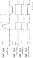
- Figs. 5(a) to 5(d) demonstrate selection of the air-fuel ratio measuring range (i.e., the narrow range R1 or the wide range R2 ) of the microcomputer 20, the contact a or b of the switch 44, and the amplification factor GB or GA in response to a change in air-fuel (A/F) ratio.
- the air-fuel ratio measuring range i.e., the narrow range R1 or the wide range R2
- the contact a or b of the switch 44 the contact a or b of the switch 44, and the amplification factor GB or GA in response to a change in air-fuel (A/F) ratio.
- the microcomputer 20 sets the air-fuel ratio measuring range thereof to the wide range R2.
- the sensor control circuit 30 controls the switch 44 and establishes the electrical connection between the operational amplifier 39 and the contact b to select a lower one (i.e., GB) of the amplification factors GB and GA.
- the engine ECU 25 analyzes the output of the A/F sensor to diagnose the operation of the A/F sensor.
- the engine ECU 25 resumes the stoichiometric feedback control.
- the microcomputer 20 returns the air-fuel ratio measuring range thereof to the narrow range R1 and switches the connection of the operational amplifier 39 to the contact b to the contact a through the switch 44 to select the higher amplification factor GA.
- the engine ECU 25 When the vehicle has been started to be accelerated at time t3, so that the load on the engine is increased highly, the engine ECU 25 performs the rich feedback control.
- the microcomputer 20 like in the fuel-cut off mode, sets the air-fuel ratio measuring range thereof to the wide range R2.
- the sensor control circuit 30 controls the switch 44 to establish the electrical connection of the operational amplifier 39 to the contact b to select the lower amplification factor GB.
- the sensor control circuit 30 is designed to select any one or two of the amplifying resistors 41 to 43 as the input resistor or the feedback resistor in the amplifier circuit 38 using the switch 44 to switch the amplification factor of the amplifier circuit 38 between the higher and lower ones. In other words, the sensor control circuit 30 is permitted to change the resolution in measuring the air-fuel ratio as required, thus ensuring desired accuracy in a selected air-fuel ratio measuring range.
- the selection of the amplification factors of the amplifier circuit 38 is, as described above, achieved by turning on or off the switch 44 to select the resistance values of the input resistor and the feedback resistor in the amplifier circuit 38, thus eliminating the need for a plurality of operational amplifiers, as used in the conventional structure, as discussed in the introductory part of this application, to select one of a plurality of amplification factors.
- This permits the structure of the sensor control circuit 30 to be reduced in size and produced at a decreased cost, and the required number of terminals to be decreased.
- the microcomputer 20 is designed to switch between the narrow range R1 (near the stoichiometric air-fuel ratio) and the wide range R2 to sample the output of the A/F sensor as a function of the air-fuel ratio of a mixture charged into the engine, thereby enabling stoichiometric air-fuel ratio control (i.e., the stoichiometric feedback control) to be performed with high accuracy, the diagnosis of the A/F sensor to be made using an output of the A/F sensor during the fuel cut-off mode of the engine in the wide range R2, and the rich feedback control to be performed accurately when it is required to increase the load on the engine.
- stoichiometric air-fuel ratio control i.e., the stoichiometric feedback control
- Fig. 6 illustrates the sensor control circuit 30 according to the second embodiment of the invention which is different from the first embodiment in that the current-measuring resistor 32 is connected to the negative terminal of the sensor element 10.
- the same reference numbers as employed in the first embodiment will refer to the same parts, and explanation thereof in detail will be omitted here.
- the negative (-) terminal of the sensor element 10 connects with the reference voltage circuit 33 through the current-measuring resistor 32 and the operational amplifier 31.
- the positive (+) terminal of the sensor element 10 connects with the voltage application control circuit 35 through the operational amplifier 34.
- the voltage appearing at a junction D of the end of the current-measuring resistor 32 is kept at the same level as that of the reference voltage source 33 (i.e., the reference voltage Vf ) .
- the sensor element current Ip flows through the current-measuring resistor 32.
- the voltage appearing at the junction E changes with a change in the sensor element current Ip.
- the voltage application control circuit 35 works to monitor the voltage at the junction E and determine the target voltage Vp to be applied to the sensor element 10 as a function of the monitored voltage, for example, by look-up using the target applying voltage line LX1, as illustrated in Fig. 3 .
- the voltage application control circuit 35 then controls the operational amplifier 34 to bring the voltage at the junction A into agreement with the target voltage Vp.
- the amplifier circuit 38 connects with the junctions D and E leading to the ends of the current-measuring resistor 32.
- the A/F output voltage that is an output of the amplifier circuit 38 is inputted to the A/D converter of the microcomputer 20.
- the amplifier circuit 38 is made up of the operational amplifier 39, the series-connected amplifying resistors 41, 42, and 43, and the switch 44 made of, for example, a MOS transistor.
- the amplifier circuit 38 has the same structure as the one in Fig. 1 .
- the switch 44 like the first embodiment, works to establish the electrical connection of the operational amplifier 39 with the contact a or b selectively to change the amplification factor of the amplifier circuit 38 between the higher and lower one.
- the amplifier circuit 38 When the switch 44 establishes, as illustrated in the drawing, the electrical connection between the operational amplifier 39 and the contact a, the amplifier circuit 38 has the amplification factor GA, as represented by equation (1), as described above. Alternatively, when the switch 44 establishes the electrical connection between the operational amplifier 39 and the contact b, the amplifier circuit 38 has the amplification factor GB, as represented by equation (2), as described above.
- the structure of the sensor control circuit 30 of this embodiment offers the same effects, as described in the first embodiment.
- Fig. 7(a) illustrates the sensor control circuit 30 according to the third embodiment of the invention which is a modification of the one of the second embodiment in Fig. 6 .
- the same reference numbers as employed in Fig. 6 will refer to the same parts, and explanation thereof in detail will be omitted here.
- the sensor control circuit 30 includes an amplifier circuit 50 connecting with the junctions D and E leading to the ends of the current-measuring resistor 32.
- the amplifier circuit 50 works to output the A/F output voltage to the A/D converter of the microcomputer 20.
- the amplifier circuit 50 is made up of an operational amplifier 51, series-connected amplifying resistors 51, 52, and 53, and a switch 55 made of, for example, a MOS transistor.
- the resistors 51, 52, and 53 have resistance values R1, R2, and R3, respectively.
- the amplifier circuit 50 has a signal input line which extends from the minus terminal of the operational amplifier 51.
- the signal input line has two branch lines one of which connects with a junction between the resistors 52 and 53 and the other connects with a junction between the resistors 53 and 54.
- the switch 55 is disposed the minus terminal of the operational amplifier 51 and the junction of the resistors 53 and 54.
- the switch 55 is of a normally open type which is closed in response to the range switching request signal outputted from the microcomputer 20.
- the amplifying resistor 52 serves as the input resistor in the amplifier circuit 50, and the amplifying resistors 53 and 54 serve as the feedback resistor in the amplifier circuit 50.
- the amplifying resistor 52 serves as the input resistor in the amplifier circuit 50
- the amplifying resistor 54 serves as the feedback resistor in the amplifier circuit 50.
- Fig. 7(b) illustrates a modification of the sensor control circuit 30 of Fig. 7(a) .
- the amplifier circuit 50 has two amplifying resistors 56 and 57 serving as the input resistor and an amplifying resistor 58 serving as the feedback resistor.
- a switch 59 which is made of, for example, a MOS transistor is connected in series with the amplifying resistor 56.
- the switch 59 is of a normally closed type which is opened in response to the range switching request signal outputted from the microcomputer 20.
- the amplifying resistors 56, 57, and 58 have resistance values R1, R2, and R3, respectively.
- a combination of the amplifying resistors 56 and 57 serves as the input resistor in the amplifier circuit 50, and the amplifying resistor 58 serves as the feedback resistor in the amplifier circuit 50.
- the amplifying resistor 57 serves as the input resistor in the amplifier circuit 50
- the amplifying resistor 58 serves as the feedback resistor in the amplifier circuit 50.
- Figs. 7(a) and 7(b) has an always-on connection line which connects the operational amplifier 51 and any of the amplifying resistors 56 to 58 constantly without the switch 55 or 59, thus avoiding temporal opening of the signal input line to the amplifier circuit 50 upon switching of the switch 55 or 59. This ensures the stability of the A/F output voltage to be produced by the amplifier circuit 50.
- Fig. 8(a) illustrates a sensor element 60 according to the fourth embodiment of the invention which is different in structure from the one illustrated in Fig. 2 and may be fabricated in the A/F sensor as used in the first embodiment instead of the sensor element 10.
- the sensor element 60 includes a laminate of two solid electrolyte layers 61 and 62.
- the solid electrolyte layer 61 has electrodes 63 and 64 affixed to opposed surfaces thereof.
- the solid electrolyte layer 62 has electrodes 65 and 66 affixed to opposed surfaces thereof.
- Each of the electrodes 63, 64, and 65 is viewed in the drawing as being made up of right and left separate parts, but, it is, in practice, formed by a single plate having a connecting portion (not shown) extending in a transverse direction in the drawing.
- the solid electrolyte layer 61 and the electrodes 63 and 64 constitute a pump cell 71.
- the solid electrolyte layer 62 and the electrodes 65 and 66 constitute an oxygen sensor cell 72.
- the sensor element 60 also includes a gas inlet 67 through which exhaust gas of the automotive engine enters and a porous diffusion layer 68, an air duct 69, and a heater 70.
- the structure and operation of this type of sensor element are disclosed in, for example, US 6,295,862 B1 , assigned to the same assignee as that of this application.
- the potential at the electrode 66 of the oxygen sensor cell 72 is inputted to a minus input terminal of a comparator 75.
- the reference voltage Vref is inputted to a plus input terminal of the comparator 75.
- a current-measuring resistor 76 is connected between the electrode 63 of the pump cell 71 and an output of the comparator 75.
- the output of the sensor element 60 is developed at junctions A and B leading to ends of the current-measuring resistor 76.
- the oxygen sensor cell 72 works to produce an electromotive force which has one of two discrete values (e.g., 0V and 0.9V) selectively as a function of whether the exhaust gas is on the rich side or the lean side of a stoichiometric point corresponding to a stoichiometric air-fuel ratio of mixture charged into the engine. For instance, when the exhaust gas is on the lean side, the oxygen sensor cell 72 produces a lower electromotive force, so that the level of output of the comparator 75 (i.e., the voltage at the junction B ) rises. This causes the current to flow from the junction B to the junction A through the current-measuring resistor 76.
- two discrete values e.g., 0V and 0.9V
- the oxygen sensor cell 72 Conversely, when the exhaust gas is on the rich side, the oxygen sensor cell 72 produces a higher electromotive force, so that the level of output of the comparator 75 (i.e., the voltage at the junction B ) drops. This causes the current to flow from the junction A to the junction B through the current-measuring resistor 76.
- the oxygen sensor cell 72 is generally also called an electromotive force cell or an oxygen concentration sensor cell.
- Fig. 8(b) shows a sensor element 80 according to the fifth embodiment of the invention which may be built in the A/F sensor, as employed in each of the above embodiments.
- the sensor element 100 includes three solid electrolyte layers 81, 82, and 83.
- the solid electrolyte layer 81 has electrodes 84 and 85 affixed to opposed surfaces thereof.
- the solid electrolyte layer 82 has electrodes 86 and 87 affixed to opposed surfaces thereof.
- the solid electrolyte layer 81 and the electrodes 84 and 85 form a pump cell 91.
- the solid electrolyte layer 82 and the electrodes 86 and 87 form an oxygen sensor cell 91.
- the solid electrolyte layer 83 forms a wall defining an oxygen reference chamber 88.
- the sensor element 80 is, like the sensor element 10, of a laminated structure.
- the sensor element 80 also includes a porous diffusion layer 89 and a gas chamber 90 into which exhaust gas of the automotive engine enter.
- the oxygen sensor cell 92 operates, like the oxygen sensor cell 72 illustrated in Fig. 8(a) , as an electromotive force cell or an oxygen concentration sensor cell.
- Fig. 9 shows a sensor control circuit 100 for the two-cell sensor cell 60, as illustrated in Fig. 8(a) .
- the differential amplifier 110 is connected to the junctions A and B leading to ends of the current-measuring resistor 103.
- the A/F output voltage that is an output of the differential amplifier 110 is outputted to a microcomputer (not shown) such as the one illustrated in Fig. 1 .
- the differential amplifier 110 includes an operational amplifier 111, amplifying resistors 113, 114, 115, 117, 118, and 119, and switches 112 and 116.
- the switch 112 is disposed on a signal input line leading to a positive input terminal (i.e., a non-inverting input terminal) of the operational amplifier 111.
- the switch 112 has contacts a and b which connect with ends of the amplifying resistor 114 that is a middle one of the amplifying resistors 113 to 115 connected in series.
- the switch 112 normally establishes an electrical connection between the contact a and the positive input terminal of the operational amplifier 111.
- the switch 116 is disposed on a signal input line leading to a negative input terminal (i.e., an inverting input terminal) of the operational amplifier 111.
- the switch 116 has contacts c and d which connect with ends of the amplifying resistor 118 that is a middle one of the amplifying resistors 117 to 119 connected in series.
- the switch 116 normally establishes an electrical connection between the contact c and the negative input terminal of the operational amplifier 111.
- the switch 112 When the range switching request signal is outputted from the microcomputer, the switch 112 establishes an electrical connection between the operational amplifier 111 and the contact b. Similarly, the switch 116 establishes an electrical connection between the operational amplifier 111 and the contact d. This results in switching between a higher and a lower amplification factor in the differential amplifier 110.
- the switching between the amplification factors, that is, between the narrow and wide ranges R1 and R2 is made in the same manner as described in the first embodiment, and explanation thereof in detail will be omitted here.
- Fig. 10 illustrates a sensor control circuit 120 which is a modification of the one of Fig. 9 .
- the electromotive force elevates the voltage at a junction C1 up to 3.45V, thereby causing the voltage at a junction C2 in the feedback circuit 121 to drop, which leads to an elevation in voltage at the junction A.
- the exhaust gas when the exhaust gas is on the rich side, it will cause the current to flow from the junction A to the junction B through the current-measuring resistor 122.
- the exhaust gas when the exhaust gas is on the lean side, it will cause the current to flow from the junction B to the junction A through the current-measuring resistor 122.
- the amplifier circuit 130 is connected to the junctions A and B leading to ends of the current-measuring resistor 122.
- the A/F output voltage that is an output of the amplifier circuit 130 is outputted to a microcomputer (not shown) such as the one illustrated in Fig. 1 .
- the amplifier circuit 130 includes an operational amplifier 131, amplifying resistors 133, 134, and 135, and a switch 132.
- the switch 132 is disposed on a signal input line leading to a negative input terminal (i.e., an inverting input terminal) of the operational amplifier 131.
- the switch 132 has contacts a and b which connect with ends of the amplifying resistor 134 that is a middle one of the amplifying resistors 133 to 135 connected in series.
- the switch 132 normally establishes an electrical connection between the contact a and the negative input terminal of the operational amplifier 131.
- the switch 132 When the range switching request signal is outputted from the microcomputer, the switch 132 establishes an electrical connection between the operational amplifier 131 and the contact b, thereby resulting in switching between a higher and a lower amplification factor in the amplifier circuit 130.
- the switching between the amplification factors, that is, between the narrow and wide ranges R1 and R2 is made in the same manner as described in the first embodiment, and explanation thereof in detail will be omitted here.
- Each of the sensor control circuits of the above embodiments may also be designed to select one of three or more amplification factors, as required, which is achieved in the same manner as described above by controlling the operations of the switches to distribute the amplifying resistors into the input resistor and the feedback resistor in the amplifier circuit.
- the gas concentration measuring apparatus in each of the embodiments may also be designed to measure the concentration of HC or CO contained in the exhaust gases of the automotive engine.
- the measurement of concentration of HC or CO is achieved by pumping excessive oxygen (O 2 ) out of the first gas chamber using the pump cell and decomposing HC or CO contained in the gasses entering the second gas chamber using the sensor cell to produce an electric signal indicative of the concentration of HC or CO.
Claims (7)
- Gaskonzentrationsmessvorrichtung mit:einem Gassensor, der mit einem Sensorelement (10) versehen ist, das aus einem festen Elektrolyt (11) gemacht ist und so arbeitet, dass es einen Sensorstrom beim Anlegen einer Spannung daran als eine Funktion einer Konzentration eines ausgewählten Gases produziert;einem strommessenden Widerstand (32), der verwendet wird, um den Sensorstrom, der durch das Sensorelement (10) fließt, zu messen;einer Verstärkungsschaltung, die mit einem Operationsverstärker (39) und einer Vielzahl von Verstärkungswiderständen (41, 42, 43) versehen ist, wobei die Verstärkungsschaltung zum Verstärken des Sensorstroms, wie er durch den strommessenden Widerstand gemessen wird, arbeitet;einer Gaskonzentrationsmessschaltung, die arbeitet, um die Konzentration des Gases basierend auf dem Sensorstrom, wie er durch die Verstärkungsschaltung verstärkt wurde, zu bestimmen; undeinem Schalter (44), der dazu ausgelegt ist, eine Beziehung in einer elektrischen Verbindung zwischen dem Operationsverstärker und den Verstärkungswiderständen zu schalten, um die verstärkenden Widerstände in einen Eingangswiderstand und einen Rückkopplungswiderstand für den Operationsverstärker zu verteilen, und einen Verstärkungsfaktor der Verstärkerschaltung zu ändern, wobeider Schalter an einer Eingabeleitung, die sich von dem strommessenden Widerstand und dem Operationsverstärker erstreckt, angeordnet ist.
- Gaskonzentrationsmessvorrichtung nach Anspruch 1, wobei
die Gaskonzentrationsmessschaltung ausgelegt ist, die Konzentration des Gases in einem ausgewählten einer Vielzahl von Messbereichen zu bestimmen,
die Gaskonzentrationsmessschaltung ausgelegt ist, einen Betrieb des Schalters so auszulegen, dass der Verstärkungsfaktor der Verstärkungsschaltung erhöht wird, wenn es nötig ist, einen engeren der Messbereiche auszuwählen,
die Gaskonzentrationsmessschaltung ausgelegt ist, den Betrieb des Schalters so zu steuern, dass der Verstärkungsfaktor der Verstärkungsschaltung verringert wird, wenn es nötig ist, einen breiteren der Messbereiche auszuwählen. - Gaskonzentrationsmessvorrichtung nach Anspruch 1, wobei
die Verstärkungswiderstände drei Widerstände sind, die in Reihe verbunden sind und wobei
der Schalter so arbeitet, dass zumindest einer der Widerstände als der Eingangswiderstand und die anderen Widerstände als der Rückkopplungswiderstand ausgewählt werden. - Gaskonzentrationsmessvorrichtung nach Anspruch 1, wobei ferner
die Eingangsleitung eine erste und eine zweite Zweigleitung enthält, die sich parallel zueinander erstrecken, die erste Zweigleitung zumindest einen der Verstärkungswiderstände aufweist und wobei der Schalter daran angeordnet ist, und die zweite Zweigleitung die anderen Verstärkungswiderstände aufweist, die daran angeordnet sind. - Gaskonzentrationsmessvorrichtung nach Anspruch 1, wobei
das ausgewählte Gas eine ausgewählte Gaskomponente von Abgasemissionen von einer internen Verbrennungsmaschine ist,
die Gaskonzentrationsmessvorrichtung ausgelegt ist, eine Konzentration der ausgewählten Gaskomponente zum Bestimmen eines Luft-Treibstoffverhältnisses einer Mischung, die in die interne Verbrennungsmaschine geladen wird, in einem ausgewählten Bereich aus einem engen Bereich, der um ein stöchiometrisches Luft-Treibstoffverhältnis definiert ist, und in einem breiten Bereich, der breiter als der enge Bereich ist und sich von einem fetten Luft-Treibstoffverhältnis zu einem mageren Luft-Treibstoffverhältnis erstreckt, zu berechnen, und wobei
die Gaskonzentrationsmessschaltung ausgelegt ist, den Betrieb des Schalters so zu steuern, dass er Verstärkungsfaktoren in der Verstärkerschaltung hat, die zwischen den engen und breiten Bereichen verschieden sind. - Gaskonzentrationsmessvorrichtung nach Anspruch 5, wobei
der breite Bereich so definiert ist, dass er zumindest einen aus einem atmosphärischen Luftäquivalentwert, wenn die interne Verbrennungsmaschine einem Treibstoffabschneiden unterzogen wird, und einem Wert eines Luft-Treibstoffverhältnis während eines Verbrennens eines fetten Luft/Treibstoffverhältnisses durch die internen Verbrennungsmaschine enthält. - Gaskonzentrationsmessvorrichtung nach einem der Ansprüche 1 bis 6, wobei die Eingangsleitung zu dem Operationsverstärker eine hohe Impedanz hat, sodass eine Widerstandskomponente des Schalters ignoriert werden kann.
Applications Claiming Priority (1)
| Application Number | Priority Date | Filing Date | Title |
|---|---|---|---|
| JP2006146392A JP4697052B2 (ja) | 2006-05-26 | 2006-05-26 | ガス濃度検出装置 |
Publications (2)
| Publication Number | Publication Date |
|---|---|
| EP1860431A1 EP1860431A1 (de) | 2007-11-28 |
| EP1860431B1 true EP1860431B1 (de) | 2017-07-26 |
Family
ID=38377302
Family Applications (1)
| Application Number | Title | Priority Date | Filing Date |
|---|---|---|---|
| EP07106934.8A Active EP1860431B1 (de) | 2006-05-26 | 2007-04-25 | Gaskonzentrationmessvorrichtung mit mehreren Verstärkungsbereichen |
Country Status (3)
| Country | Link |
|---|---|
| US (1) | US7981265B2 (de) |
| EP (1) | EP1860431B1 (de) |
| JP (1) | JP4697052B2 (de) |
Families Citing this family (11)
| Publication number | Priority date | Publication date | Assignee | Title |
|---|---|---|---|---|
| US8333875B2 (en) | 2007-02-05 | 2012-12-18 | Denso Corporation | Sensor control device |
| EP2093562B1 (de) * | 2008-02-19 | 2017-08-30 | Denso Corporation | Gassensorsteuervorrichtungsystem |
| JP5091055B2 (ja) * | 2008-08-27 | 2012-12-05 | 日本特殊陶業株式会社 | ガス濃度検出装置、ガス濃度検出システム |
| JP5041488B2 (ja) * | 2008-09-19 | 2012-10-03 | 日本特殊陶業株式会社 | センサ制御装置 |
| US20120055790A1 (en) * | 2010-09-03 | 2012-03-08 | Newman Robert L | Gas Sensor Assembly with Interior Heat Dissipation, Sealing, and Support Plug |
| DE102010042013A1 (de) * | 2010-10-06 | 2012-04-12 | Robert Bosch Gmbh | Verfahren zur Einstellung einer Temperatur eines Sensorelements |
| CN102590289B (zh) * | 2012-02-27 | 2014-05-14 | 上海恩尼克思工业仪器有限公司 | 催化燃烧型气体传感器 |
| JP5920306B2 (ja) * | 2013-10-02 | 2016-05-18 | トヨタ自動車株式会社 | ハイブリッド車両およびハイブリッド車両の制御方法 |
| US10443526B2 (en) * | 2016-09-14 | 2019-10-15 | Denso Corporation | Air-fuel ratio sensing device |
| JP2019026403A (ja) * | 2017-07-26 | 2019-02-21 | セイコーエプソン株式会社 | プリンター、及びプリンターの制御方法 |
| CN110988089B (zh) * | 2019-12-16 | 2021-05-14 | 江西农业大学 | 一种宽量程数字电化学分析装置及检测方法 |
Citations (1)
| Publication number | Priority date | Publication date | Assignee | Title |
|---|---|---|---|---|
| EP0774834A1 (de) * | 1995-11-10 | 1997-05-21 | Fujitsu Limited | Verstärkerschaltung mit variabler Verstärkung |
Family Cites Families (11)
| Publication number | Priority date | Publication date | Assignee | Title |
|---|---|---|---|---|
| JPH0750070B2 (ja) * | 1986-03-03 | 1995-05-31 | 本田技研工業株式会社 | 酸素濃度検出装置 |
| US4914424A (en) * | 1987-03-02 | 1990-04-03 | Japan Storage Battery Company, Limited | Oxygen concentration monitor using galvanic cell type oxygen sensor |
| JPH0961397A (ja) * | 1995-08-30 | 1997-03-07 | Denso Corp | 空燃比検出装置 |
| US5980728A (en) * | 1996-09-24 | 1999-11-09 | Rosemont Analytical Inc. | Diagnostic method and apparatus for solid electrolyte gas analyzer |
| JP3487159B2 (ja) * | 1997-05-21 | 2004-01-13 | 株式会社デンソー | ガス濃度検出装置及びその製造方法 |
| JP4005273B2 (ja) | 1998-09-16 | 2007-11-07 | 株式会社デンソー | ガス濃度検出装置 |
| JP2000137018A (ja) | 1998-11-02 | 2000-05-16 | Denso Corp | ガス濃度検出装置とそれに用いるガス濃度センサ |
| US6497135B1 (en) * | 2000-09-08 | 2002-12-24 | Delphi Technologies, Inc. | Controller for use with wide range oxygen sensor |
| JP2004205488A (ja) | 2002-11-08 | 2004-07-22 | Denso Corp | ガス濃度検出装置 |
| JP4124119B2 (ja) * | 2003-01-30 | 2008-07-23 | 株式会社デンソー | ガス濃度検出装置 |
| JP4177345B2 (ja) * | 2005-03-28 | 2008-11-05 | 日本特殊陶業株式会社 | センサ制御装置及び空燃比検出装置 |
-
2006
- 2006-05-26 JP JP2006146392A patent/JP4697052B2/ja active Active
-
2007
- 2007-04-25 EP EP07106934.8A patent/EP1860431B1/de active Active
- 2007-05-09 US US11/797,961 patent/US7981265B2/en active Active
Patent Citations (1)
| Publication number | Priority date | Publication date | Assignee | Title |
|---|---|---|---|---|
| EP0774834A1 (de) * | 1995-11-10 | 1997-05-21 | Fujitsu Limited | Verstärkerschaltung mit variabler Verstärkung |
Also Published As
| Publication number | Publication date |
|---|---|
| EP1860431A1 (de) | 2007-11-28 |
| JP4697052B2 (ja) | 2011-06-08 |
| US20070284248A1 (en) | 2007-12-13 |
| JP2007315943A (ja) | 2007-12-06 |
| US7981265B2 (en) | 2011-07-19 |
Similar Documents
| Publication | Publication Date | Title |
|---|---|---|
| EP1860431B1 (de) | Gaskonzentrationmessvorrichtung mit mehreren Verstärkungsbereichen | |
| US7578914B2 (en) | Gas concentration measuring apparatus designed to compensate for output error | |
| US6442998B2 (en) | Gas concentration measuring apparatus compensating for error component of output signal | |
| US6921883B2 (en) | Gas sensor and method of heating the same | |
| US4306957A (en) | Device for producing control signal for feedback control of air/fuel ratio | |
| EP0987546B1 (de) | Vorrichtung zum Fühlen einer Gaskonzentration | |
| EP0994345B1 (de) | Leistungsversorgungssteuersystem für die Heizung eines Gaskonzentrationsfühlers | |
| EP1764613B1 (de) | Apparat zum Messen von Gaskonzentrationen | |
| US7776194B2 (en) | Gas concentration measuring apparatus designed to compensate for output error | |
| US7481913B2 (en) | High-resolution gas concentration measuring apparatus | |
| US20060011476A1 (en) | Gas concentration measuring apparatus designed to ensuring accuracy of determining resistance of gas sensor element | |
| US4302312A (en) | Device for producing control signal for feedback control of air/fuel mixing ratio | |
| US4664773A (en) | Air-to-fuel ratio sensor for an automobile | |
| EP1744154B1 (de) | Gaskonzentrationsmessgerät zur raschen Bestimmung des Aktivationsgrades von Gassensoren | |
| US8721856B2 (en) | Gas sensor control system ensuring increased measurement accuracy | |
| JP4485718B2 (ja) | 空燃比システムの異常検出システム | |
| US20050217347A1 (en) | Gas concentration measuring apparatus with failure monitor | |
| US7455761B2 (en) | Nitrogen oxide sensor with attenuated oxygen dependence of the NOx signal | |
| KR920004816B1 (ko) | 자동차용 트라이스테이트(tristate) 공연비센서 | |
| US6589409B2 (en) | Multilayered gas sensing element employable in an exhaust system of an internal combustion engine | |
| JPH05240829A (ja) | 空燃比センサ |
Legal Events
| Date | Code | Title | Description |
|---|---|---|---|
| PUAI | Public reference made under article 153(3) epc to a published international application that has entered the european phase |
Free format text: ORIGINAL CODE: 0009012 |
|
| AK | Designated contracting states |
Kind code of ref document: A1 Designated state(s): AT BE BG CH CY CZ DE DK EE ES FI FR GB GR HU IE IS IT LI LT LU LV MC MT NL PL PT RO SE SI SK TR |
|
| AX | Request for extension of the european patent |
Extension state: AL BA HR MK YU |
|
| 17P | Request for examination filed |
Effective date: 20080310 |
|
| AKX | Designation fees paid |
Designated state(s): DE FR GB |
|
| 17Q | First examination report despatched |
Effective date: 20140324 |
|
| GRAP | Despatch of communication of intention to grant a patent |
Free format text: ORIGINAL CODE: EPIDOSNIGR1 |
|
| INTG | Intention to grant announced |
Effective date: 20170217 |
|
| RIN1 | Information on inventor provided before grant (corrected) |
Inventor name: SUZUKI, TOSHIYUKI Inventor name: KAWASE, TOMOO Inventor name: HADA, SATOSHI Inventor name: AKIMOTO, KATSUHIDE Inventor name: KUROKAWA, EIICHI |
|
| GRAS | Grant fee paid |
Free format text: ORIGINAL CODE: EPIDOSNIGR3 |
|
| GRAA | (expected) grant |
Free format text: ORIGINAL CODE: 0009210 |
|
| AK | Designated contracting states |
Kind code of ref document: B1 Designated state(s): DE FR GB |
|
| REG | Reference to a national code |
Ref country code: GB Ref legal event code: FG4D |
|
| REG | Reference to a national code |
Ref country code: DE Ref legal event code: R096 Ref document number: 602007051748 Country of ref document: DE |
|
| REG | Reference to a national code |
Ref country code: GB Ref legal event code: 746 Effective date: 20180123 |
|
| REG | Reference to a national code |
Ref country code: DE Ref legal event code: R084 Ref document number: 602007051748 Country of ref document: DE |
|
| REG | Reference to a national code |
Ref country code: FR Ref legal event code: PLFP Year of fee payment: 12 |
|
| REG | Reference to a national code |
Ref country code: DE Ref legal event code: R097 Ref document number: 602007051748 Country of ref document: DE |
|
| PLBE | No opposition filed within time limit |
Free format text: ORIGINAL CODE: 0009261 |
|
| STAA | Information on the status of an ep patent application or granted ep patent |
Free format text: STATUS: NO OPPOSITION FILED WITHIN TIME LIMIT |
|
| 26N | No opposition filed |
Effective date: 20180430 |
|
| PGFP | Annual fee paid to national office [announced via postgrant information from national office to epo] |
Ref country code: FR Payment date: 20230420 Year of fee payment: 17 Ref country code: DE Payment date: 20230420 Year of fee payment: 17 |
|
| PGFP | Annual fee paid to national office [announced via postgrant information from national office to epo] |
Ref country code: GB Payment date: 20230419 Year of fee payment: 17 |