EP1859971A1 - Device for blocking the suspension strut of a motor vehicle - Google Patents
Device for blocking the suspension strut of a motor vehicle Download PDFInfo
- Publication number
- EP1859971A1 EP1859971A1 EP07004848A EP07004848A EP1859971A1 EP 1859971 A1 EP1859971 A1 EP 1859971A1 EP 07004848 A EP07004848 A EP 07004848A EP 07004848 A EP07004848 A EP 07004848A EP 1859971 A1 EP1859971 A1 EP 1859971A1
- Authority
- EP
- European Patent Office
- Prior art keywords
- strut
- spacer body
- spring
- spacer
- motor vehicle
- Prior art date
- Legal status (The legal status is an assumption and is not a legal conclusion. Google has not performed a legal analysis and makes no representation as to the accuracy of the status listed.)
- Granted
Links
Images
Classifications
-
- F—MECHANICAL ENGINEERING; LIGHTING; HEATING; WEAPONS; BLASTING
- F16—ENGINEERING ELEMENTS AND UNITS; GENERAL MEASURES FOR PRODUCING AND MAINTAINING EFFECTIVE FUNCTIONING OF MACHINES OR INSTALLATIONS; THERMAL INSULATION IN GENERAL
- F16F—SPRINGS; SHOCK-ABSORBERS; MEANS FOR DAMPING VIBRATION
- F16F9/00—Springs, vibration-dampers, shock-absorbers, or similarly-constructed movement-dampers using a fluid or the equivalent as damping medium
- F16F9/32—Details
- F16F9/58—Stroke limiting stops, e.g. arranged on the piston rod outside the cylinder
-
- B—PERFORMING OPERATIONS; TRANSPORTING
- B60—VEHICLES IN GENERAL
- B60G—VEHICLE SUSPENSION ARRANGEMENTS
- B60G15/00—Resilient suspensions characterised by arrangement, location or type of combined spring and vibration damper, e.g. telescopic type
- B60G15/02—Resilient suspensions characterised by arrangement, location or type of combined spring and vibration damper, e.g. telescopic type having mechanical spring
- B60G15/06—Resilient suspensions characterised by arrangement, location or type of combined spring and vibration damper, e.g. telescopic type having mechanical spring and fluid damper
- B60G15/062—Resilient suspensions characterised by arrangement, location or type of combined spring and vibration damper, e.g. telescopic type having mechanical spring and fluid damper the spring being arranged around the damper
-
- B—PERFORMING OPERATIONS; TRANSPORTING
- B60—VEHICLES IN GENERAL
- B60G—VEHICLE SUSPENSION ARRANGEMENTS
- B60G17/00—Resilient suspensions having means for adjusting the spring or vibration-damper characteristics, for regulating the distance between a supporting surface and a sprung part of vehicle or for locking suspension during use to meet varying vehicular or surface conditions, e.g. due to speed or load
- B60G17/005—Suspension locking arrangements
-
- B—PERFORMING OPERATIONS; TRANSPORTING
- B60—VEHICLES IN GENERAL
- B60G—VEHICLE SUSPENSION ARRANGEMENTS
- B60G2202/00—Indexing codes relating to the type of spring, damper or actuator
- B60G2202/20—Type of damper
- B60G2202/24—Fluid damper
-
- B—PERFORMING OPERATIONS; TRANSPORTING
- B60—VEHICLES IN GENERAL
- B60G—VEHICLE SUSPENSION ARRANGEMENTS
- B60G2204/00—Indexing codes related to suspensions per se or to auxiliary parts
- B60G2204/40—Auxiliary suspension parts; Adjustment of suspensions
- B60G2204/44—Centering or positioning means
- B60G2204/4402—Spacers or shims
-
- B—PERFORMING OPERATIONS; TRANSPORTING
- B60—VEHICLES IN GENERAL
- B60G—VEHICLE SUSPENSION ARRANGEMENTS
- B60G2204/00—Indexing codes related to suspensions per se or to auxiliary parts
- B60G2204/40—Auxiliary suspension parts; Adjustment of suspensions
- B60G2204/45—Stops limiting travel
- B60G2204/4502—Stops limiting travel using resilient buffer
-
- B—PERFORMING OPERATIONS; TRANSPORTING
- B60—VEHICLES IN GENERAL
- B60G—VEHICLE SUSPENSION ARRANGEMENTS
- B60G2204/00—Indexing codes related to suspensions per se or to auxiliary parts
- B60G2204/40—Auxiliary suspension parts; Adjustment of suspensions
- B60G2204/46—Means for locking the suspension
- B60G2204/4604—Means for locking the suspension mechanically, e.g. using a hook as anticreep mechanism
-
- B—PERFORMING OPERATIONS; TRANSPORTING
- B60—VEHICLES IN GENERAL
- B60G—VEHICLE SUSPENSION ARRANGEMENTS
- B60G2206/00—Indexing codes related to the manufacturing of suspensions: constructional features, the materials used, procedures or tools
- B60G2206/01—Constructional features of suspension elements, e.g. arms, dampers, springs
- B60G2206/90—Maintenance
- B60G2206/92—Tools or equipment used for assembling
Definitions
- the present invention relates to a device for blocking a strut of a motor vehicle for transporting the motor vehicle according to the preamble of claim 1.
- a device for blocking a spring in a strut in which a spacer element is provided for transporting a vehicle.
- the spacer element consists of at least one clipable into the spring segment of a hard elastic plastic, which is supported with its lower, free end to a spring plate of the shock absorber.
- a clipping into the turns of the spring takes place in one or more bearing receptacles of the segment to the effect that an upper receptacle serves as Einfädel recording and the segment is pivoted about this bearing on the stationary spring plate of the shock absorber and is supported thereon.
- Another device for blocking a shock absorber is for example from US 3,591,161 known.
- the present invention is concerned with the problem of providing an improved or at least another embodiment for a device for blocking a strut of a motor vehicle of the generic type.
- the present invention is based on the general idea to provide in a generic device for blocking a shock absorber of a motor vehicle spacers, said spacers are formed substantially C-shaped and arranged at the strut mounted device radially within a coil spring of the strut and with their C. -shaped shape engage around an axial portion of a damper device of the shock absorber.
- the device may have a plurality of spacers, which are arranged in the axial direction of the spring strut side by side and thereby allow an accurate limitation of the maximum available spring travel.
- the coil spring of the shock absorber is usually arranged between two spring plates and surrounds or surrounds at least one axial section of the damper device.
- a height of a spacer is smaller than a clear width between two turns of the coil spring in the axial direction of the same in the neutral position of the shock absorber. This allows a problem-free radial insertion of the spacers by the remaining between the turns of the coil spring spacings, whereby a mounting of the spacers on the strut designed particularly simple.
- the device has a arranged on the spacer body grip element which projects radially outwardly by the coil spring when mounted on the strut device.
- a grip element which for example in the form of a loop or a Tear tab is formed, facilitates the removal of the spacer body after the transport of the vehicle and eliminates the need for a complex and technically difficult passing through the distances between the individual turns of the coil spring.
- a grip element easy handling of the spacer body, which simplifies its handling even in the unassembled state.
- the spacer body is made of plastic.
- a trained plastic spacer can be produced in almost any shape and also cost. At the same time, influencing the material properties of the plastic influences the elasticity of the plastic and thus the maximum permissible spring travel.
- the spacer body is axially stackable, wherein it is also conceivable that it is positively stackable.
- a positive stackability on the one hand facilitates the storage of the spacers in the non-use state and on the other hand ensures an exact positioning of the spacers on the strut in the mounted state.
- a form-fit stackability can be achieved, for example, via a corresponding complementary formation of mutually facing sides of the spacers.
- the C-shaped spacer body is designed such that it surrounds the axial portion of the damper device by more than 180 °. This causes a self-locking position of the spacer on the axial portion of the damper device and ensures a reliable hold of the spacer body on the strut during transport of the motor vehicle.
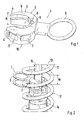
- a spacer body 1 has a C-shaped section 2.
- the C-shaped section 2 is preferably formed so that the two C-legs 3, 3 'at the free ends 4, 4' are slightly directed towards each other. This makes it possible to encompass a damper device inserted between the two C-legs 3, 3 '(see FIG. 2) by more than 180 °.
- the two C-legs 3, 3 ' are connected to one another via a connecting region 5, wherein according to FIG. 1, a grip element 6 is arranged on an outer side of the connecting region 5.
- the grip element 6 is in this case designed, for example, as a ring or as a tear tab, and is preferably embodied in one piece with the spacer body 1.
- the grip element 6 may be arranged eccentrically with respect to the height H of the spacer body 1, which facilitates mounting on a suspension strut 13.
- the two C-legs 3, 3 ' can be moved more easily towards and away from one another, the deeper the notch 8 protrudes into the connection region 5.
- the spacer body 1 made of plastic, in particular made of elastic plastic, and thereby inexpensive and easy to produce in almost any shape. At the same time, this makes it possible to influence the elasticity of the material properties of the plastic.
- an upper side 9 of the spacer body 1 is frusto-conical and preferably has a shape complementary to a lower side 10 of the spacer body 1. This allows a positive stacking of a plurality of spacers 1 one above the other (see Fig. 2).
- the height H of the spacer body 1 is preferably about 20 to 25 mm and is in any case smaller than the inside width W between two turns 11 of a coil spring 12 of the strut 13 shown in Fig. 2.
- the spacer body 1 is part of a device for blocking the strut 13, wherein the strut 13 is disposed on a motor vehicle, not shown. The blocking of the strut 13 is required during the transport of the motor vehicle.
- the strut 13 has a damper device 14 and the above-mentioned coil spring 12.
- the damper device 14 may be formed, for example, as a shock absorber, while the coil spring 12 is disposed between two spring plates, not shown, and surrounds at least a portion of the damper device 14 and surrounds.
- the damper device 14 is thus arranged radially inside the coil spring 12.
- two spacers 1 are so with the axial portion of the damper device 14 connected that the C-shaped portion 2 of the spacer body 1 surrounds this axial portion of the damper device 14.
- the gripping element 6 protrudes radially outward through the helical spring 12 when the device is mounted on the suspension strut 13, so that a removal or attachment of the spacer body 1 is possible simply and without difficulty. 2, it is also clear why the height H of the spacer body 1 should in any case be smaller than the inside width W between two turns 11 of the helical spring 12, so that the spacer body 1 can be moved between the turns 11 ,
- top 9 and the bottom 10 of the spacer body 1 can be easily arrange a plurality of spacers 1 on the strut 13, whereby the desired blocking of the strut 13 can be achieved.
Landscapes
- Engineering & Computer Science (AREA)
- Mechanical Engineering (AREA)
- General Engineering & Computer Science (AREA)
- Vehicle Body Suspensions (AREA)
- Fluid-Damping Devices (AREA)
Abstract
Description
Die vorliegende Erfindung betrifft eine Vorrichtung zum Blockieren eines Federbeins eines Kraftfahrzeugs zum Transport des Kraftfahrzeugs gemäß dem Oberbegriff des Anspruchs 1.The present invention relates to a device for blocking a strut of a motor vehicle for transporting the motor vehicle according to the preamble of
Beim Transport von Fahrzeugen ist es üblich, die Federwirkung der Federbeine außer Kraft zu setzen, indem beispielsweise Distanzelemente zwischen den einzelnen Windungen der Feder des Federbeins eingeklemmt werden und dadurch deren Federweg begrenzen.When transporting vehicles, it is common to override the spring action of the struts, for example, by clamping spacers between the individual turns of the spring of the strut and thereby limit their travel.
Aus der
Eine weitere Vorrichtung zum Blockieren eines Federbeins ist beispielsweise aus der
Die vorliegende Erfindung beschäftigt sich mit dem Problem, für eine Vorrichtung zum Blockieren eines Federbeins eines Kraftfahrzeugs der gattungsgemäßen Art eine verbesserte oder zumindest eine andere Ausführungsform anzugeben.The present invention is concerned with the problem of providing an improved or at least another embodiment for a device for blocking a strut of a motor vehicle of the generic type.
Dieses Problem wird erfindungsgemäß durch den Gegenstand des unabhängigen Anspruchs gelöst. Vorteilhafte Ausführungsformen sind Gegenstand der abhängigen Ansprüche.This problem is solved according to the invention by the subject matter of the independent claim. Advantageous embodiments are the subject of the dependent claims.
Die vorliegende Erfindung beruht auf dem allgemeinen Gedanken, bei einer gattungsgemäßen Vorrichtung zum Blockieren eines Federbeins eines Kraftfahrzeugs Distanzkörper vorzusehen, wobei diese Distanzkörper im wesentlichen C-förmig ausgebildet sind und bei am Federbein montierter Vorrichtung radial innerhalb einer Schraubenfeder des Federbeins angeordnet sind und mit ihrer C-förmigen Gestalt einen Axialabschnitt einer Dämpfereinrichtung des Federbeins umgreifen. Die Vorrichtung kann dabei mehrere Distanzkörper aufweisen, welche in axialer Richtung des Federbeins nebeneinander angeordnet werden und dadurch eine genaue Begrenzung des maximal zur Verfügung stehenden Federwegs erlauben. Die Schraubenfeder des Federbeins ist dabei üblicherweise zwischen zwei Federtellern angeordnet und umgreift bzw. umrundet zumindest einen Axialabschnitt der Dämpfereinrichtung. Durch die erfindungsgemäße Lösung ist es möglich, das Federbein hinsichtlich seines Federwegs einfach zu begrenzen, indem entsprechende Distanzkörper zwischen den einzelnen Windungen der Schraubenfeder hindurchgeschoben werden und anschließend in Eingriff mit der Dämpfereinrichtung gebracht werden.The present invention is based on the general idea to provide in a generic device for blocking a shock absorber of a motor vehicle spacers, said spacers are formed substantially C-shaped and arranged at the strut mounted device radially within a coil spring of the strut and with their C. -shaped shape engage around an axial portion of a damper device of the shock absorber. The device may have a plurality of spacers, which are arranged in the axial direction of the spring strut side by side and thereby allow an accurate limitation of the maximum available spring travel. The coil spring of the shock absorber is usually arranged between two spring plates and surrounds or surrounds at least one axial section of the damper device. By the solution according to the invention, it is possible to easily limit the strut with respect to its spring travel by appropriate spacers between the individual turns of the coil spring are pushed through and then brought into engagement with the damper device.
Zweckmäßig ist eine Höhe eines Distanzkörpers kleiner als eine lichte Weite zwischen zwei Windungen der Schraubenfeder in axialer Richtung derselben in Neutralstellung des Federbeins. Dies ermöglicht ein problemloses radiales Einführen der Distanzkörper durch die zwischen den Windungen der Schraubenfeder verbleibenden Abstände, wodurch sich eine Montage der Distanzkörper am Federbein besonders einfach gestaltet.Suitably, a height of a spacer is smaller than a clear width between two turns of the coil spring in the axial direction of the same in the neutral position of the shock absorber. This allows a problem-free radial insertion of the spacers by the remaining between the turns of the coil spring spacings, whereby a mounting of the spacers on the strut designed particularly simple.
Bei einer vorteilhaften Ausführungsform der erfindungsgemäßen Lösung weist die Vorrichtung ein am Distanzkörper angeordnetes Griffelement auf, welches bei am Federbein angebrachter Vorrichtung radial nach außen durch die Schraubenfeder ragt. Ein derartiges Griffelement, welches beispielsweise in Form einer Schlaufe oder ein Reißlasche ausgebildet ist, erleichtert das Entfernen des Distanzkörpers nach dem Transport des Fahrzeugs und erübrigt ein aufwändiges und handwerklich schwieriges Hindurchgreifen durch die Abstände zwischen den einzelnen Windungen der Schraubenfeder. Gleichzeitig erlaubt ein derartiges Griffelement eine leichte Handhabung des Distanzkörpers, wodurch sich dessen Handling auch im nicht montierten Zustand vereinfacht.In an advantageous embodiment of the solution according to the invention, the device has a arranged on the spacer body grip element which projects radially outwardly by the coil spring when mounted on the strut device. Such a grip element, which for example in the form of a loop or a Tear tab is formed, facilitates the removal of the spacer body after the transport of the vehicle and eliminates the need for a complex and technically difficult passing through the distances between the individual turns of the coil spring. At the same time allows such a grip element easy handling of the spacer body, which simplifies its handling even in the unassembled state.
Zweckmäßig ist der Distanzkörper aus Kunststoff ausgebildet. Ein aus Kunststoff ausgebildete Distanzkörper lässt sich in nahezu jeder beliebigen Form und zudem kostengünstig herstellen. Gleichzeitig kann durch die Beeinflussung der Materialeigenschaften des Kunststoffs Einfluss auf die Elastizität des Kunststoffs und damit auf den maximal zulässigen Federweg genommen werden.Suitably, the spacer body is made of plastic. A trained plastic spacer can be produced in almost any shape and also cost. At the same time, influencing the material properties of the plastic influences the elasticity of the plastic and thus the maximum permissible spring travel.
Bei einer weiteren vorteilhaften Ausführungsform der erfindungsgemäßen Lösung ist der Distanzkörper axial stapelbar ausgebildet, wobei darüber hinaus denkbar ist, dass er formschlüssig stapelbar ist. Eine derartige formschlüssige Stapelbarkeit erleichtert einerseits die Lagerung der Distanzkörper im Nichtgebrauchszustand und sichert andererseits eine exakte Positionierung der Distanzkörper am Federbein im montierten Zustand. Eine formschlüssige Stapelbarkeit kann dabei beispielsweise über eine entsprechende komplementäre Ausbildung einander zugewandter Seiten der Distanzkörper erreicht werden.In a further advantageous embodiment of the solution according to the invention, the spacer body is axially stackable, wherein it is also conceivable that it is positively stackable. Such a positive stackability on the one hand facilitates the storage of the spacers in the non-use state and on the other hand ensures an exact positioning of the spacers on the strut in the mounted state. A form-fit stackability can be achieved, for example, via a corresponding complementary formation of mutually facing sides of the spacers.
Bei einer besonders bevorzugten Ausführungsform der erfindungsgemäßen Lösung ist der C-förmige Distanzkörper so ausgebildet, dass er den Axialabschnitt der Dämpfereinrichtung um mehr als 180° umgreift. Dies bewirkt eine selbstsichernde Lage des Distanzkörpers am Axialabschnitt der Dämpfereinrichtung und gewährleistet einen zuverlässigen Halt der Distanzkörper am Federbein während des Transport des Kraftfahrzeugs.In a particularly preferred embodiment of the solution according to the invention, the C-shaped spacer body is designed such that it surrounds the axial portion of the damper device by more than 180 °. This causes a self-locking position of the spacer on the axial portion of the damper device and ensures a reliable hold of the spacer body on the strut during transport of the motor vehicle.
Weitere wichtige Merkmale und Vorteile der Erfindung ergeben sich aus den Unteransprüchen, aus den Zeichnungen und aus der zugehörigen Figurenbeschreibung anhand der Zeichnungen.Other important features and advantages of the invention will become apparent from the dependent claims, from the drawings and from the associated figure description with reference to the drawings.
Es versteht sich, dass die vorstehend genannten und die nachstehend noch zu erläuternden Merkmale nicht nur in der jeweils angegebenen Kombination, sondern auch in anderen Kombinationen oder in Alleinstellung verwendbar sind, ohne den Rahmen der vorliegenden Erfindung zu verlassen.It is understood that the features mentioned above and those yet to be explained below can be used not only in the particular combination given, but also in other combinations or in isolation, without departing from the scope of the present invention.
Bevorzugte Ausführungsbeispiele der Erfindung sind in den Zeichnungen dargestellt und werden in der nachfolgenden Beschreibung näher erläutert, wobei sich gleiche Bezugszeichen auf gleiche oder ähnliche oder funktional gleiche Bauteile beziehen.Preferred embodiments of the invention are illustrated in the drawings and will be described in more detail in the following description, wherein like reference numerals refer to the same or similar or functionally identical components.
Dabei zeigen, jeweils schematisch,
- Fig. 1
- einen erfindungsgemäßen Distanzkörper,
- Fig. 2
- eine in ein Federbein eingebaute Vorrichtung zum Blockieren des Federbeins.
- Fig. 1
- a spacer body according to the invention,
- Fig. 2
- a built in a strut device for locking the shock absorber.
Entsprechend Fig. 1 weist ein erfindungsgemäßer Distanzkörper 1 einen C-förmig ausgebildeten Abschnitt 2 auf. Der C-förmige Abschnitt 2 ist dabei vorzugsweise so ausgebildet, dass dessen beiden C-Schenkel 3, 3' an deren freien Enden 4, 4' leicht aufeinander zu gerichtet sind. Dies ermöglicht ein Umgreifen einer zwischen die beiden C-Schenkel 3, 3' eingeführten Dämpfereinrichtung (vgl. Fig. 2) um mehr als 180°. Die beiden C-Schenkel 3, 3' sind über einen Verbindungsbereich 5 miteinander verbunden, wobei gemäß Fig. 1 an einer Außenseite des Verbindungsbereichs 5 ein Griffelement 6 angeordnet ist. Das Griffelement 6 ist hierbei beispielsweise als Ring bzw. als Reißlasche ausgebildet und vorzugsweise einstückig mit dem Distanzkörper 1 ausgeführt. Das Griffelement 6 kann im Bezug auf die Höhe H des Distanzkörpers 1 außermittig angeordnet sein, was eine Montage an einem Federbein 13 erleichtert. An einer Innenseite des Verbindungsbereichs 5 ist eine im wesentliche orthogonal zu den beiden C-Schenkeln 3 und 3' orientierte Kerbe 8 vorgesehen, welche dazu dient, die federnden Eigenschaften der beiden C-Schenkeln 3, 3' zu verbessern. Dabei können die beiden C-Schenkel 3, 3' umso leichter aufeinander zu bzw. voneinander weg bewegt werden, je tiefer die Kerbe 8 in den Verbindungsbereich 5 hineinragt. Desweiteren weist der Distanzkörper 1 außenseitige Ausnehmungen 7 auf, welche je nach Größe die Elastizität des Distanzkörpers 1 beeinflussen.According to FIG. 1, a
Prinzipiell ist der Distanzkörper 1 aus Kunststoff, insbesondere aus elastischem Kunststoff ausgebildet, und dadurch kostengünstig und in nahe zu jeder beliebigen Form einfach herstellbar. Gleichzeitig lässt sich dadurch über die Materialeigenschaften des Kunststoffes Einfluss auf dessen Elastizität nehmen.In principle, the
Wie weiter aus Fig. 1 zu entnehmen ist, ist eine Oberseite 9 des Distanzkörpers 1 kegelstumpfartig ausgebildet und besitzt vorzugsweise eine zu einer Unterseite 10 des Distanzkörpers 1 komplementäre Form. Dies ermöglicht ein formschlüssiges Stapeln mehrerer Distanzkörper 1 übereinander (vgl. Fig. 2). Die Höhe H des Distanzkörpers 1 beträgt vorzugsweise ca. 20 bis 25mm und ist in jedem Fall kleiner als die lichte Weite W zwischen zwei Windungen 11 einer Schraubenfeder 12 des in Fig. 2 dargestellten Federbeins 13. Generell ist der Distanzkörper 1 Teil einer Vorrichtung zum Blockieren des Federbeins 13, wobei das Federbein 13 an einem nicht dargestellten Kraftfahrzeug angeordnet ist. Die Blockierung des Federbeins 13 wird dabei während des Transports des Kraftfahrzeugs benötigt.As can further be seen from FIG. 1, an
Wie in Fig. 2 dargestellt ist, weist das Federbein 13 eine Dämpfereinrichtung 14 sowie die obengenannte Schraubenfeder 12 auf. Die Dämpfereinrichtung 14 kann dabei beispielsweise als Stoßdämpfer ausgebildet sein, während die Schraubenfeder 12 zwischen zwei nicht gezeigten Federntellern angeordnet ist und zumindest einen Teilbereich der Dämpfereinrichtung 14 umgreift bzw. umschließt. Die Dämpfereinrichtung 14 ist somit radial innerhalb der Schraubenfeder 12 angeordnet. Wie in Fig. 2 weiter gezeigt, sind zwei Distanzkörper 1 derart mit dem Axialabschnitt der Dämpfereinrichtung 14 verbunden, dass der C-förmige Abschnitt 2 des Distanzkörpers 1 diesen Axialabschnitt der Dämpfereinrichtung 14 umgreift. Das Griffelement 6 ragt bei am Federbein 13 angebrachter Vorrichtung radial nach außen durch die Schraubenfeder 12, so dass ein Entfernen bzw. Anbringen der Distanzkörper 1 einfach und problemlos möglich ist. Bei der Betrachtung der Fig. 2 wird auch klar, warum die Höhe H des Distanzkörpers 1 auf jeden Fall kleiner sein sollte als die lichte Weite W zwischen zwei Windungen 11 der Schraubenfeder 12, so dass der Distanzkörper 1 zwischen den Windungen 11 hindurch bewegt werden kann.As shown in Fig. 2, the
Durch die zueinander komplementäre Ausbildung der Oberseite 9 und der Unterseite 10 des Distanzkörpers 1 lassen sich einfach mehrere Distanzkörper 1 am Federbein 13 anordnen, wodurch die gewünschte Blockierung des Federbeins 13 erreicht werden kann.By mutually complementary formation of the
Selbstverständlich ist auch denkbar, dass einzelne Distanzkörper 1 mit unterschiedlicher Höhe H unterschiedliche Farben aufweisen, wodurch eine schnell visuelle Kontrolle der richtig oder falsch zusammengestellten Vorrichtung zum Blockierungen des Federbeins 13 möglich ist.Of course, it is also conceivable that
Claims (10)
Applications Claiming Priority (1)
| Application Number | Priority Date | Filing Date | Title |
|---|---|---|---|
| DE102006024268A DE102006024268A1 (en) | 2006-05-24 | 2006-05-24 | Device for blocking a strut of a motor vehicle |
Publications (2)
| Publication Number | Publication Date |
|---|---|
| EP1859971A1 true EP1859971A1 (en) | 2007-11-28 |
| EP1859971B1 EP1859971B1 (en) | 2010-11-17 |
Family
ID=37891634
Family Applications (1)
| Application Number | Title | Priority Date | Filing Date |
|---|---|---|---|
| EP07004848A Not-in-force EP1859971B1 (en) | 2006-05-24 | 2007-03-09 | Device for blocking the suspension strut of a motor vehicle |
Country Status (4)
| Country | Link |
|---|---|
| US (1) | US7419147B2 (en) |
| EP (1) | EP1859971B1 (en) |
| AT (1) | ATE488388T1 (en) |
| DE (2) | DE102006024268A1 (en) |
Cited By (2)
| Publication number | Priority date | Publication date | Assignee | Title |
|---|---|---|---|---|
| WO2016055706A1 (en) * | 2014-10-09 | 2016-04-14 | Peugeot Citroen Automobiles Sa | Protection system for hydraulic shock absorber comprising cutouts for a compression strap |
| GB2588485A (en) * | 2019-10-01 | 2021-04-28 | Shifukang Ind Co Ltd | Suspension support device |
Families Citing this family (5)
| Publication number | Priority date | Publication date | Assignee | Title |
|---|---|---|---|---|
| DE102010010654B4 (en) | 2010-03-09 | 2019-01-31 | Dr. Ing. H.C. F. Porsche Aktiengesellschaft | mounting aid |
| DE102018007973A1 (en) | 2018-10-09 | 2019-03-28 | Daimler Ag | Method for detecting at least one blocking element for limiting a spring travel of at least one shock absorber of a vehicle, control device for carrying out such a method, and vehicle having such a control device |
| DE102020113706B3 (en) * | 2020-05-20 | 2021-04-29 | Dr. Ing. H.C. F. Porsche Aktiengesellschaft | Assembly aid and method for assembling and disassembling blocking elements on a suspension strut |
| CN112092556B (en) * | 2020-09-22 | 2021-11-09 | 广东博智林机器人有限公司 | Suspension mechanism, gear train device and movable chassis |
| DE102022129595A1 (en) | 2022-11-09 | 2024-05-16 | Audi Aktiengesellschaft | Locking device for a spring and/or damper strut of a motor vehicle |
Citations (4)
| Publication number | Priority date | Publication date | Assignee | Title |
|---|---|---|---|---|
| US3591161A (en) | 1969-04-25 | 1971-07-06 | Moog Industries Inc | Spring spacer |
| JPH0681886A (en) * | 1992-09-07 | 1994-03-22 | Toyota Motor Corp | Car height holding spacer |
| DE19751215C1 (en) | 1997-11-19 | 1998-12-10 | Porsche Ag | Spring block for motor vehicle suspension |
| EP1498636A2 (en) * | 2003-07-18 | 2005-01-19 | Dr.Ing. h.c.F. Porsche Aktiengesellschaft | Device for blocking a suspension |
Family Cites Families (10)
| Publication number | Priority date | Publication date | Assignee | Title |
|---|---|---|---|---|
| US2760772A (en) * | 1954-02-01 | 1956-08-28 | Thomas E Mcintyre | Spring adjusting assemblies |
| US2829883A (en) * | 1957-02-14 | 1958-04-08 | Copeland Clayton Simpson | Resilience adjusting means for coil springs |
| US3141661A (en) * | 1962-04-20 | 1964-07-21 | Jamco Inc | Spacer for insertion between adjacent convolutions of a coil spring |
| US3773309A (en) * | 1972-05-30 | 1973-11-20 | Perfect Equip Corp | Coil spring spacer |
| US3866896A (en) * | 1973-04-02 | 1975-02-18 | Crawford Howard E | Resilient coil spring adjuster and method of fabrication |
| US4529179A (en) * | 1983-07-28 | 1985-07-16 | Perfection Spring & Stamping Corp. | Internal nut for adjusting the tension of a coil spring |
| DE20021481U1 (en) | 2000-12-19 | 2001-06-13 | PP-Plastic Peuker OHG, 08459 Neukirchen | Travel limiting element |
| DE20221481U1 (en) * | 2001-07-17 | 2006-01-12 | Ziehl-Abegg Ag | External rotor motor has annular connecting plate placed on clamping/connection plate with plugs that engage accommodation chambers or intermediate contact elements and plug strip |
| DE20112593U1 (en) * | 2001-07-31 | 2001-10-31 | Colour Tuning GmbH, 95119 Naila | Travel limiter for automotive shock absorbers |
| BE1014477A6 (en) * | 2001-11-15 | 2003-11-04 | Azimuth Internat Trading Nv | TRAVEL LIMIT IN ONE ELEMENT FOR SUSPENSION AND limit the TRAVEL TO SUCH TRAVEL LIMIT. |
-
2006
- 2006-05-24 DE DE102006024268A patent/DE102006024268A1/en not_active Withdrawn
-
2007
- 2007-03-09 AT AT07004848T patent/ATE488388T1/en active
- 2007-03-09 EP EP07004848A patent/EP1859971B1/en not_active Not-in-force
- 2007-03-09 DE DE502007005646T patent/DE502007005646D1/en active Active
- 2007-05-24 US US11/805,877 patent/US7419147B2/en active Active
Patent Citations (4)
| Publication number | Priority date | Publication date | Assignee | Title |
|---|---|---|---|---|
| US3591161A (en) | 1969-04-25 | 1971-07-06 | Moog Industries Inc | Spring spacer |
| JPH0681886A (en) * | 1992-09-07 | 1994-03-22 | Toyota Motor Corp | Car height holding spacer |
| DE19751215C1 (en) | 1997-11-19 | 1998-12-10 | Porsche Ag | Spring block for motor vehicle suspension |
| EP1498636A2 (en) * | 2003-07-18 | 2005-01-19 | Dr.Ing. h.c.F. Porsche Aktiengesellschaft | Device for blocking a suspension |
Cited By (4)
| Publication number | Priority date | Publication date | Assignee | Title |
|---|---|---|---|---|
| WO2016055706A1 (en) * | 2014-10-09 | 2016-04-14 | Peugeot Citroen Automobiles Sa | Protection system for hydraulic shock absorber comprising cutouts for a compression strap |
| FR3027083A1 (en) * | 2014-10-09 | 2016-04-15 | Peugeot Citroen Automobiles Sa | PROTECTION SYSTEM FOR HYDRAULIC SHOCK ABSORBER COMPRISING CUTTERS FOR A COMPRESSION STRAP |
| GB2588485A (en) * | 2019-10-01 | 2021-04-28 | Shifukang Ind Co Ltd | Suspension support device |
| GB2588485B (en) * | 2019-10-01 | 2023-05-10 | Shifukang Ind Co Ltd | Suspension support device |
Also Published As
| Publication number | Publication date |
|---|---|
| US20070278728A1 (en) | 2007-12-06 |
| DE102006024268A1 (en) | 2007-11-29 |
| US7419147B2 (en) | 2008-09-02 |
| DE502007005646D1 (en) | 2010-12-30 |
| ATE488388T1 (en) | 2010-12-15 |
| EP1859971B1 (en) | 2010-11-17 |
Similar Documents
| Publication | Publication Date | Title |
|---|---|---|
| EP1859971B1 (en) | Device for blocking the suspension strut of a motor vehicle | |
| DE10106915C2 (en) | suspension arrangement | |
| EP2983943B1 (en) | Longitudinal adjuster for a vehicle seat and vehicle seat | |
| EP0140107B1 (en) | Spring compressor, especially for motor vehicle axle springs | |
| DE102009016139A1 (en) | elastomer joint | |
| WO2010017875A1 (en) | Control piston for slider valves and method for the production thereof | |
| DE102009038317A1 (en) | Adjustable steering column for a motor vehicle | |
| EP2158412B1 (en) | Bearing arrangement | |
| DE102014100805A1 (en) | Device for preventing incorrect filling of a container | |
| DE3345638A1 (en) | RIM FOR MOTOR VEHICLES AND THE LIKE | |
| DE202008010206U1 (en) | socket | |
| DE202013104266U1 (en) | Arrangement for connecting components | |
| DE102018128203A1 (en) | Electrical connector part and electrical connector system with lock | |
| DE102010016874A1 (en) | Agricultural device for solidifying the soil | |
| EP3240961A1 (en) | Disc brake | |
| DE2906734B2 (en) | Roller in twin wheel arrangement | |
| DE102016115536A1 (en) | safety claw | |
| DE102007042034A1 (en) | Fixing system for fastening components, in particular for motor vehicles | |
| DE102020113706B3 (en) | Assembly aid and method for assembling and disassembling blocking elements on a suspension strut | |
| DE4030884C2 (en) | Temple storage for paint rollers and the like | |
| DE29518501U1 (en) | Device for connecting the intake manifold of a fuel pump to a fuel filter made of plastic | |
| DE102013101491A1 (en) | Height-adjustable round bar guide | |
| DE9201120U1 (en) | Winding spool for tape or thread-shaped winding material | |
| DE29801172U1 (en) | Spring tensioner for coil springs with a low number of turns | |
| DE10144242B4 (en) | Arrangement and method for height adjustment on a front axle |
Legal Events
| Date | Code | Title | Description |
|---|---|---|---|
| PUAI | Public reference made under article 153(3) epc to a published international application that has entered the european phase |
Free format text: ORIGINAL CODE: 0009012 |
|
| AK | Designated contracting states |
Kind code of ref document: A1 Designated state(s): AT BE BG CH CY CZ DE DK EE ES FI FR GB GR HU IE IS IT LI LT LU LV MC MT NL PL PT RO SE SI SK TR |
|
| AX | Request for extension of the european patent |
Extension state: AL BA HR MK YU |
|
| RAP1 | Party data changed (applicant data changed or rights of an application transferred) |
Owner name: DR. ING. H.C. F. PORSCHE AKTIENGESELLSCHAFT |
|
| 17P | Request for examination filed |
Effective date: 20080528 |
|
| RAP1 | Party data changed (applicant data changed or rights of an application transferred) |
Owner name: DR. ING. H.C. F. PORSCHE AKTIENGESELLSCHAFT |
|
| 17Q | First examination report despatched |
Effective date: 20080630 |
|
| AKX | Designation fees paid |
Designated state(s): AT DE ES FR GB IT |
|
| RAP1 | Party data changed (applicant data changed or rights of an application transferred) |
Owner name: DR. ING. H.C. F. PORSCHE AG |
|
| GRAP | Despatch of communication of intention to grant a patent |
Free format text: ORIGINAL CODE: EPIDOSNIGR1 |
|
| GRAS | Grant fee paid |
Free format text: ORIGINAL CODE: EPIDOSNIGR3 |
|
| GRAA | (expected) grant |
Free format text: ORIGINAL CODE: 0009210 |
|
| AK | Designated contracting states |
Kind code of ref document: B1 Designated state(s): AT DE ES FR GB IT |
|
| REG | Reference to a national code |
Ref country code: GB Ref legal event code: FG4D Free format text: NOT ENGLISH |
|
| REF | Corresponds to: |
Ref document number: 502007005646 Country of ref document: DE Date of ref document: 20101230 Kind code of ref document: P |
|
| PGFP | Annual fee paid to national office [announced via postgrant information from national office to epo] |
Ref country code: IT Payment date: 20110323 Year of fee payment: 5 |
|
| PG25 | Lapsed in a contracting state [announced via postgrant information from national office to epo] |
Ref country code: ES Free format text: LAPSE BECAUSE OF FAILURE TO SUBMIT A TRANSLATION OF THE DESCRIPTION OR TO PAY THE FEE WITHIN THE PRESCRIBED TIME-LIMIT Effective date: 20110228 |
|
| PLBE | No opposition filed within time limit |
Free format text: ORIGINAL CODE: 0009261 |
|
| STAA | Information on the status of an ep patent application or granted ep patent |
Free format text: STATUS: NO OPPOSITION FILED WITHIN TIME LIMIT |
|
| 26N | No opposition filed |
Effective date: 20110818 |
|
| REG | Reference to a national code |
Ref country code: DE Ref legal event code: R097 Ref document number: 502007005646 Country of ref document: DE Effective date: 20110818 |
|
| PG25 | Lapsed in a contracting state [announced via postgrant information from national office to epo] |
Ref country code: IT Free format text: LAPSE BECAUSE OF NON-PAYMENT OF DUE FEES Effective date: 20120309 |
|
| REG | Reference to a national code |
Ref country code: AT Ref legal event code: MM01 Ref document number: 488388 Country of ref document: AT Kind code of ref document: T Effective date: 20120309 |
|
| PG25 | Lapsed in a contracting state [announced via postgrant information from national office to epo] |
Ref country code: AT Free format text: LAPSE BECAUSE OF NON-PAYMENT OF DUE FEES Effective date: 20120309 |
|
| REG | Reference to a national code |
Ref country code: FR Ref legal event code: PLFP Year of fee payment: 10 |
|
| REG | Reference to a national code |
Ref country code: FR Ref legal event code: PLFP Year of fee payment: 11 |
|
| REG | Reference to a national code |
Ref country code: FR Ref legal event code: PLFP Year of fee payment: 12 |
|
| PGFP | Annual fee paid to national office [announced via postgrant information from national office to epo] |
Ref country code: GB Payment date: 20180321 Year of fee payment: 12 |
|
| PGFP | Annual fee paid to national office [announced via postgrant information from national office to epo] |
Ref country code: FR Payment date: 20180323 Year of fee payment: 12 |
|
| GBPC | Gb: european patent ceased through non-payment of renewal fee |
Effective date: 20190309 |
|
| PG25 | Lapsed in a contracting state [announced via postgrant information from national office to epo] |
Ref country code: GB Free format text: LAPSE BECAUSE OF NON-PAYMENT OF DUE FEES Effective date: 20190309 |
|
| PG25 | Lapsed in a contracting state [announced via postgrant information from national office to epo] |
Ref country code: FR Free format text: LAPSE BECAUSE OF NON-PAYMENT OF DUE FEES Effective date: 20190331 |
|
| PGFP | Annual fee paid to national office [announced via postgrant information from national office to epo] |
Ref country code: DE Payment date: 20200227 Year of fee payment: 14 |
|
| REG | Reference to a national code |
Ref country code: DE Ref legal event code: R119 Ref document number: 502007005646 Country of ref document: DE |
|
| PG25 | Lapsed in a contracting state [announced via postgrant information from national office to epo] |
Ref country code: DE Free format text: LAPSE BECAUSE OF NON-PAYMENT OF DUE FEES Effective date: 20211001 |