EP1858107A1 - Battery Structure - Google Patents
Battery Structure Download PDFInfo
- Publication number
- EP1858107A1 EP1858107A1 EP20070108435 EP07108435A EP1858107A1 EP 1858107 A1 EP1858107 A1 EP 1858107A1 EP 20070108435 EP20070108435 EP 20070108435 EP 07108435 A EP07108435 A EP 07108435A EP 1858107 A1 EP1858107 A1 EP 1858107A1
- Authority
- EP
- European Patent Office
- Prior art keywords
- battery structure
- active material
- heat dissipating
- unit cell
- battery
- Prior art date
- Legal status (The legal status is an assumption and is not a legal conclusion. Google has not performed a legal analysis and makes no representation as to the accuracy of the status listed.)
- Withdrawn
Links
- 239000006182 cathode active material Substances 0.000 claims abstract description 64
- 239000006183 anode active material Substances 0.000 claims abstract description 61
- 239000003792 electrolyte Substances 0.000 claims abstract description 27
- 239000000463 material Substances 0.000 claims description 67
- 229920005989 resin Polymers 0.000 claims description 34
- 239000011347 resin Substances 0.000 claims description 34
- 239000002131 composite material Substances 0.000 claims description 22
- 239000002180 crystalline carbon material Substances 0.000 claims description 13
- 238000004519 manufacturing process Methods 0.000 claims description 11
- 229910008088 Li-Mn Inorganic materials 0.000 claims description 7
- 229910006327 Li—Mn Inorganic materials 0.000 claims description 7
- 239000004760 aramid Substances 0.000 claims description 7
- 229920003235 aromatic polyamide Polymers 0.000 claims description 7
- 229920001225 polyester resin Polymers 0.000 claims description 6
- 229920005673 polypropylene based resin Polymers 0.000 claims description 6
- 239000011358 absorbing material Substances 0.000 claims description 3
- 239000010410 layer Substances 0.000 description 176
- 230000000052 comparative effect Effects 0.000 description 67
- OKTJSMMVPCPJKN-UHFFFAOYSA-N Carbon Chemical compound [C] OKTJSMMVPCPJKN-UHFFFAOYSA-N 0.000 description 30
- 229910052799 carbon Inorganic materials 0.000 description 25
- -1 polypropylene Polymers 0.000 description 22
- 230000009286 beneficial effect Effects 0.000 description 21
- 239000002245 particle Substances 0.000 description 19
- 239000011888 foil Substances 0.000 description 14
- 239000004698 Polyethylene Substances 0.000 description 13
- 229910052782 aluminium Inorganic materials 0.000 description 13
- XAGFODPZIPBFFR-UHFFFAOYSA-N aluminium Chemical compound [Al] XAGFODPZIPBFFR-UHFFFAOYSA-N 0.000 description 13
- 239000000919 ceramic Substances 0.000 description 11
- 238000013016 damping Methods 0.000 description 11
- 238000007599 discharging Methods 0.000 description 10
- 229910010272 inorganic material Inorganic materials 0.000 description 10
- 239000011147 inorganic material Substances 0.000 description 10
- 239000008151 electrolyte solution Substances 0.000 description 9
- 229910000975 Carbon steel Inorganic materials 0.000 description 8
- 239000011245 gel electrolyte Substances 0.000 description 8
- 238000000034 method Methods 0.000 description 8
- 239000005518 polymer electrolyte Substances 0.000 description 8
- 239000002861 polymer material Substances 0.000 description 8
- 239000004743 Polypropylene Substances 0.000 description 7
- 239000010962 carbon steel Substances 0.000 description 7
- 229920001971 elastomer Polymers 0.000 description 7
- 239000007769 metal material Substances 0.000 description 7
- 229920001155 polypropylene Polymers 0.000 description 7
- 239000007787 solid Substances 0.000 description 7
- 229910052723 transition metal Inorganic materials 0.000 description 7
- 238000012360 testing method Methods 0.000 description 6
- RYGMFSIKBFXOCR-UHFFFAOYSA-N Copper Chemical compound [Cu] RYGMFSIKBFXOCR-UHFFFAOYSA-N 0.000 description 5
- WHXSMMKQMYFTQS-UHFFFAOYSA-N Lithium Chemical compound [Li] WHXSMMKQMYFTQS-UHFFFAOYSA-N 0.000 description 5
- 150000002500 ions Chemical class 0.000 description 5
- 239000002648 laminated material Substances 0.000 description 5
- 229910052744 lithium Inorganic materials 0.000 description 5
- 229920000573 polyethylene Polymers 0.000 description 5
- 150000003624 transition metals Chemical class 0.000 description 5
- 230000001133 acceleration Effects 0.000 description 4
- 239000004020 conductor Substances 0.000 description 4
- 239000010949 copper Substances 0.000 description 4
- 239000000945 filler Substances 0.000 description 4
- 239000004014 plasticizer Substances 0.000 description 4
- 238000007789 sealing Methods 0.000 description 4
- 238000001228 spectrum Methods 0.000 description 4
- 239000010935 stainless steel Substances 0.000 description 4
- 229910001220 stainless steel Inorganic materials 0.000 description 4
- WEVYAHXRMPXWCK-UHFFFAOYSA-N Acetonitrile Chemical class CC#N WEVYAHXRMPXWCK-UHFFFAOYSA-N 0.000 description 3
- ZMXDDKWLCZADIW-UHFFFAOYSA-N N,N-Dimethylformamide Chemical compound CN(C)C=O ZMXDDKWLCZADIW-UHFFFAOYSA-N 0.000 description 3
- 238000010521 absorption reaction Methods 0.000 description 3
- 230000008901 benefit Effects 0.000 description 3
- 239000011231 conductive filler Substances 0.000 description 3
- 239000011889 copper foil Substances 0.000 description 3
- 230000032798 delamination Effects 0.000 description 3
- 239000007789 gas Substances 0.000 description 3
- 239000011229 interlayer Substances 0.000 description 3
- 238000005259 measurement Methods 0.000 description 3
- 238000002844 melting Methods 0.000 description 3
- 230000008018 melting Effects 0.000 description 3
- 229920000728 polyester Polymers 0.000 description 3
- 229920002981 polyvinylidene fluoride Polymers 0.000 description 3
- 150000003839 salts Chemical class 0.000 description 3
- NYNZQNWKBKUAII-KBXCAEBGSA-N (3s)-n-[5-[(2r)-2-(2,5-difluorophenyl)pyrrolidin-1-yl]pyrazolo[1,5-a]pyrimidin-3-yl]-3-hydroxypyrrolidine-1-carboxamide Chemical compound C1[C@@H](O)CCN1C(=O)NC1=C2N=C(N3[C@H](CCC3)C=3C(=CC=C(F)C=3)F)C=CN2N=C1 NYNZQNWKBKUAII-KBXCAEBGSA-N 0.000 description 2
- YEJRWHAVMIAJKC-UHFFFAOYSA-N 4-Butyrolactone Chemical class O=C1CCCO1 YEJRWHAVMIAJKC-UHFFFAOYSA-N 0.000 description 2
- XTHFKEDIFFGKHM-UHFFFAOYSA-N Dimethoxyethane Chemical compound COCCOC XTHFKEDIFFGKHM-UHFFFAOYSA-N 0.000 description 2
- 229910002993 LiMnO2 Inorganic materials 0.000 description 2
- HBBGRARXTFLTSG-UHFFFAOYSA-N Lithium ion Chemical compound [Li+] HBBGRARXTFLTSG-UHFFFAOYSA-N 0.000 description 2
- PXHVJJICTQNCMI-UHFFFAOYSA-N Nickel Chemical compound [Ni] PXHVJJICTQNCMI-UHFFFAOYSA-N 0.000 description 2
- 239000004677 Nylon Substances 0.000 description 2
- 239000002033 PVDF binder Substances 0.000 description 2
- 229920003171 Poly (ethylene oxide) Polymers 0.000 description 2
- OFOBLEOULBTSOW-UHFFFAOYSA-N Propanedioic acid Natural products OC(=O)CC(O)=O OFOBLEOULBTSOW-UHFFFAOYSA-N 0.000 description 2
- VYPSYNLAJGMNEJ-UHFFFAOYSA-N Silicium dioxide Chemical compound O=[Si]=O VYPSYNLAJGMNEJ-UHFFFAOYSA-N 0.000 description 2
- WYURNTSHIVDZCO-UHFFFAOYSA-N Tetrahydrofuran Chemical compound C1CCOC1 WYURNTSHIVDZCO-UHFFFAOYSA-N 0.000 description 2
- GWEVSGVZZGPLCZ-UHFFFAOYSA-N Titan oxide Chemical compound O=[Ti]=O GWEVSGVZZGPLCZ-UHFFFAOYSA-N 0.000 description 2
- MCRWZBYTLVCCJJ-DKALBXGISA-N [(1s,3r)-3-[[(3s,4s)-3-methoxyoxan-4-yl]amino]-1-propan-2-ylcyclopentyl]-[(1s,4s)-5-[6-(trifluoromethyl)pyrimidin-4-yl]-2,5-diazabicyclo[2.2.1]heptan-2-yl]methanone Chemical compound C([C@]1(N(C[C@]2([H])C1)C(=O)[C@@]1(C[C@@H](CC1)N[C@@H]1[C@@H](COCC1)OC)C(C)C)[H])N2C1=CC(C(F)(F)F)=NC=N1 MCRWZBYTLVCCJJ-DKALBXGISA-N 0.000 description 2
- 230000005856 abnormality Effects 0.000 description 2
- PNEYBMLMFCGWSK-UHFFFAOYSA-N aluminium oxide Inorganic materials [O-2].[O-2].[O-2].[Al+3].[Al+3] PNEYBMLMFCGWSK-UHFFFAOYSA-N 0.000 description 2
- 239000003575 carbonaceous material Substances 0.000 description 2
- 150000004649 carbonic acid derivatives Chemical class 0.000 description 2
- 150000001875 compounds Chemical class 0.000 description 2
- 229910052802 copper Inorganic materials 0.000 description 2
- 238000004132 cross linking Methods 0.000 description 2
- 230000007423 decrease Effects 0.000 description 2
- 230000003247 decreasing effect Effects 0.000 description 2
- GNTDGMZSJNCJKK-UHFFFAOYSA-N divanadium pentaoxide Chemical compound O=[V](=O)O[V](=O)=O GNTDGMZSJNCJKK-UHFFFAOYSA-N 0.000 description 2
- 230000000694 effects Effects 0.000 description 2
- 150000002148 esters Chemical class 0.000 description 2
- 239000010439 graphite Substances 0.000 description 2
- 229910002804 graphite Inorganic materials 0.000 description 2
- 229910021385 hard carbon Inorganic materials 0.000 description 2
- 230000017525 heat dissipation Effects 0.000 description 2
- 238000010438 heat treatment Methods 0.000 description 2
- 229910001416 lithium ion Inorganic materials 0.000 description 2
- VZCYOOQTPOCHFL-UPHRSURJSA-N maleic acid Chemical compound OC(=O)\C=C/C(O)=O VZCYOOQTPOCHFL-UPHRSURJSA-N 0.000 description 2
- 239000011976 maleic acid Substances 0.000 description 2
- NUJOXMJBOLGQSY-UHFFFAOYSA-N manganese dioxide Chemical compound O=[Mn]=O NUJOXMJBOLGQSY-UHFFFAOYSA-N 0.000 description 2
- 229910052751 metal Inorganic materials 0.000 description 2
- 239000002184 metal Substances 0.000 description 2
- TZIHFWKZFHZASV-UHFFFAOYSA-N methyl formate Chemical compound COC=O TZIHFWKZFHZASV-UHFFFAOYSA-N 0.000 description 2
- 238000012986 modification Methods 0.000 description 2
- 230000004048 modification Effects 0.000 description 2
- JKQOBWVOAYFWKG-UHFFFAOYSA-N molybdenum trioxide Chemical compound O=[Mo](=O)=O JKQOBWVOAYFWKG-UHFFFAOYSA-N 0.000 description 2
- 239000004745 nonwoven fabric Substances 0.000 description 2
- 229920001778 nylon Polymers 0.000 description 2
- 230000035699 permeability Effects 0.000 description 2
- 239000005020 polyethylene terephthalate Substances 0.000 description 2
- 229920000139 polyethylene terephthalate Polymers 0.000 description 2
- 229920005606 polypropylene copolymer Polymers 0.000 description 2
- 229920001451 polypropylene glycol Polymers 0.000 description 2
- 239000002243 precursor Substances 0.000 description 2
- VZCYOOQTPOCHFL-UHFFFAOYSA-N trans-butenedioic acid Natural products OC(=O)C=CC(O)=O VZCYOOQTPOCHFL-UHFFFAOYSA-N 0.000 description 2
- 238000012546 transfer Methods 0.000 description 2
- 229910000314 transition metal oxide Inorganic materials 0.000 description 2
- KEEKMOIRJUWKNK-CABZTGNLSA-N (2S)-2-[[2-[(4R)-4-(difluoromethyl)-2-oxo-1,3-thiazolidin-3-yl]-5,6-dihydroimidazo[1,2-d][1,4]benzoxazepin-9-yl]amino]propanamide Chemical compound FC([C@H]1N(C(SC1)=O)C=1N=C2N(CCOC3=C2C=CC(=C3)N[C@H](C(=O)N)C)C=1)F KEEKMOIRJUWKNK-CABZTGNLSA-N 0.000 description 1
- BIIBYWQGRFWQKM-JVVROLKMSA-N (2S)-N-[4-(cyclopropylamino)-3,4-dioxo-1-[(3S)-2-oxopyrrolidin-3-yl]butan-2-yl]-2-[[(E)-3-(2,4-dichlorophenyl)prop-2-enoyl]amino]-4,4-dimethylpentanamide Chemical compound CC(C)(C)C[C@@H](C(NC(C[C@H](CCN1)C1=O)C(C(NC1CC1)=O)=O)=O)NC(/C=C/C(C=CC(Cl)=C1)=C1Cl)=O BIIBYWQGRFWQKM-JVVROLKMSA-N 0.000 description 1
- QIVUCLWGARAQIO-OLIXTKCUSA-N (3s)-n-[(3s,5s,6r)-6-methyl-2-oxo-1-(2,2,2-trifluoroethyl)-5-(2,3,6-trifluorophenyl)piperidin-3-yl]-2-oxospiro[1h-pyrrolo[2,3-b]pyridine-3,6'-5,7-dihydrocyclopenta[b]pyridine]-3'-carboxamide Chemical compound C1([C@H]2[C@H](N(C(=O)[C@@H](NC(=O)C=3C=C4C[C@]5(CC4=NC=3)C3=CC=CN=C3NC5=O)C2)CC(F)(F)F)C)=C(F)C=CC(F)=C1F QIVUCLWGARAQIO-OLIXTKCUSA-N 0.000 description 1
- VZSRBBMJRBPUNF-UHFFFAOYSA-N 2-(2,3-dihydro-1H-inden-2-ylamino)-N-[3-oxo-3-(2,4,6,7-tetrahydrotriazolo[4,5-c]pyridin-5-yl)propyl]pyrimidine-5-carboxamide Chemical compound C1C(CC2=CC=CC=C12)NC1=NC=C(C=N1)C(=O)NCCC(N1CC2=C(CC1)NN=N2)=O VZSRBBMJRBPUNF-UHFFFAOYSA-N 0.000 description 1
- SSORSZACHCNXSJ-UHFFFAOYSA-N 2-[2-(3,4-dichlorophenyl)-3-[2-(2-hydroxypropylamino)pyrimidin-4-yl]imidazol-4-yl]acetonitrile Chemical compound ClC=1C=C(C=CC=1Cl)C=1N(C(=CN=1)CC#N)C1=NC(=NC=C1)NCC(C)O SSORSZACHCNXSJ-UHFFFAOYSA-N 0.000 description 1
- DWKNOLCXIFYNFV-HSZRJFAPSA-N 2-[[(2r)-1-[1-[(4-chloro-3-methylphenyl)methyl]piperidin-4-yl]-5-oxopyrrolidine-2-carbonyl]amino]-n,n,6-trimethylpyridine-4-carboxamide Chemical compound CN(C)C(=O)C1=CC(C)=NC(NC(=O)[C@@H]2N(C(=O)CC2)C2CCN(CC=3C=C(C)C(Cl)=CC=3)CC2)=C1 DWKNOLCXIFYNFV-HSZRJFAPSA-N 0.000 description 1
- JWUJQDFVADABEY-UHFFFAOYSA-N 2-methyltetrahydrofuran Chemical compound CC1CCCO1 JWUJQDFVADABEY-UHFFFAOYSA-N 0.000 description 1
- UXHQLGLGLZKHTC-CUNXSJBXSA-N 4-[(3s,3ar)-3-cyclopentyl-7-(4-hydroxypiperidine-1-carbonyl)-3,3a,4,5-tetrahydropyrazolo[3,4-f]quinolin-2-yl]-2-chlorobenzonitrile Chemical compound C1CC(O)CCN1C(=O)C1=CC=C(C=2[C@@H]([C@H](C3CCCC3)N(N=2)C=2C=C(Cl)C(C#N)=CC=2)CC2)C2=N1 UXHQLGLGLZKHTC-CUNXSJBXSA-N 0.000 description 1
- RSIWALKZYXPAGW-NSHDSACASA-N 6-(3-fluorophenyl)-3-methyl-7-[(1s)-1-(7h-purin-6-ylamino)ethyl]-[1,3]thiazolo[3,2-a]pyrimidin-5-one Chemical compound C=1([C@@H](NC=2C=3N=CNC=3N=CN=2)C)N=C2SC=C(C)N2C(=O)C=1C1=CC=CC(F)=C1 RSIWALKZYXPAGW-NSHDSACASA-N 0.000 description 1
- OIFBSDVPJOWBCH-UHFFFAOYSA-N Diethyl carbonate Chemical compound CCOC(=O)OCC OIFBSDVPJOWBCH-UHFFFAOYSA-N 0.000 description 1
- KMTRUDSVKNLOMY-UHFFFAOYSA-N Ethylene carbonate Chemical compound O=C1OCCO1 KMTRUDSVKNLOMY-UHFFFAOYSA-N 0.000 description 1
- 229910007003 Li(C2F5SO2)2 Inorganic materials 0.000 description 1
- 229910001560 Li(CF3SO2)2N Inorganic materials 0.000 description 1
- 229910007966 Li-Co Inorganic materials 0.000 description 1
- 229910007960 Li-Fe Inorganic materials 0.000 description 1
- 229910010820 Li2B10Cl10 Inorganic materials 0.000 description 1
- 229910011469 Li4/3Ti5/3O4 Inorganic materials 0.000 description 1
- 229910012841 LiCoO2 a Inorganic materials 0.000 description 1
- 229910010584 LiFeO2 Inorganic materials 0.000 description 1
- 229910052493 LiFePO4 Inorganic materials 0.000 description 1
- 229910003005 LiNiO2 Inorganic materials 0.000 description 1
- 229910001290 LiPF6 Inorganic materials 0.000 description 1
- 229910012464 LiTaF6 Inorganic materials 0.000 description 1
- 229910002097 Lithium manganese(III,IV) oxide Inorganic materials 0.000 description 1
- 229910008295 Li—Co Inorganic materials 0.000 description 1
- 229910006564 Li—Fe Inorganic materials 0.000 description 1
- RJUFJBKOKNCXHH-UHFFFAOYSA-N Methyl propionate Chemical compound CCC(=O)OC RJUFJBKOKNCXHH-UHFFFAOYSA-N 0.000 description 1
- 229910002640 NiOOH Inorganic materials 0.000 description 1
- 229920002292 Nylon 6 Polymers 0.000 description 1
- 229920002302 Nylon 6,6 Polymers 0.000 description 1
- 229910019142 PO4 Inorganic materials 0.000 description 1
- 239000004952 Polyamide Substances 0.000 description 1
- XBDQKXXYIPTUBI-UHFFFAOYSA-M Propionate Chemical compound CCC([O-])=O XBDQKXXYIPTUBI-UHFFFAOYSA-M 0.000 description 1
- 241000490025 Schefflera digitata Species 0.000 description 1
- 229910009973 Ti2O3 Inorganic materials 0.000 description 1
- 229910003092 TiS2 Inorganic materials 0.000 description 1
- RTAQQCXQSZGOHL-UHFFFAOYSA-N Titanium Chemical compound [Ti] RTAQQCXQSZGOHL-UHFFFAOYSA-N 0.000 description 1
- 210000001015 abdomen Anatomy 0.000 description 1
- KXKVLQRXCPHEJC-UHFFFAOYSA-N acetic acid trimethyl ester Natural products COC(C)=O KXKVLQRXCPHEJC-UHFFFAOYSA-N 0.000 description 1
- 239000000853 adhesive Substances 0.000 description 1
- 230000001070 adhesive effect Effects 0.000 description 1
- 238000003915 air pollution Methods 0.000 description 1
- 229910045601 alloy Inorganic materials 0.000 description 1
- 239000000956 alloy Substances 0.000 description 1
- 150000001408 amides Chemical class 0.000 description 1
- 230000000712 assembly Effects 0.000 description 1
- 238000000429 assembly Methods 0.000 description 1
- DQXBYHZEEUGOBF-UHFFFAOYSA-N but-3-enoic acid;ethene Chemical compound C=C.OC(=O)CC=C DQXBYHZEEUGOBF-UHFFFAOYSA-N 0.000 description 1
- 229910010293 ceramic material Inorganic materials 0.000 description 1
- 229910052681 coesite Inorganic materials 0.000 description 1
- 230000007797 corrosion Effects 0.000 description 1
- 238000005260 corrosion Methods 0.000 description 1
- 238000002788 crimping Methods 0.000 description 1
- 229910052906 cristobalite Inorganic materials 0.000 description 1
- 230000001351 cycling effect Effects 0.000 description 1
- 238000011161 development Methods 0.000 description 1
- IEJIGPNLZYLLBP-UHFFFAOYSA-N dimethyl carbonate Chemical compound COC(=O)OC IEJIGPNLZYLLBP-UHFFFAOYSA-N 0.000 description 1
- 230000005611 electricity Effects 0.000 description 1
- 238000005516 engineering process Methods 0.000 description 1
- 230000007613 environmental effect Effects 0.000 description 1
- 150000002170 ethers Chemical class 0.000 description 1
- JBTWLSYIZRCDFO-UHFFFAOYSA-N ethyl methyl carbonate Chemical compound CCOC(=O)OC JBTWLSYIZRCDFO-UHFFFAOYSA-N 0.000 description 1
- 239000005038 ethylene vinyl acetate Substances 0.000 description 1
- 239000000446 fuel Substances 0.000 description 1
- 239000003517 fume Substances 0.000 description 1
- 230000004927 fusion Effects 0.000 description 1
- 230000020169 heat generation Effects 0.000 description 1
- 230000002706 hydrostatic effect Effects 0.000 description 1
- 229910001412 inorganic anion Inorganic materials 0.000 description 1
- 229920000554 ionomer Polymers 0.000 description 1
- 150000002596 lactones Chemical class 0.000 description 1
- 239000005001 laminate film Substances 0.000 description 1
- YADSGOSSYOOKMP-UHFFFAOYSA-N lead dioxide Inorganic materials O=[Pb]=O YADSGOSSYOOKMP-UHFFFAOYSA-N 0.000 description 1
- 229910001540 lithium hexafluoroarsenate(V) Inorganic materials 0.000 description 1
- MHCFAGZWMAWTNR-UHFFFAOYSA-M lithium perchlorate Chemical compound [Li+].[O-]Cl(=O)(=O)=O MHCFAGZWMAWTNR-UHFFFAOYSA-M 0.000 description 1
- 229910001486 lithium perchlorate Inorganic materials 0.000 description 1
- 229910001537 lithium tetrachloroaluminate Inorganic materials 0.000 description 1
- 229910001496 lithium tetrafluoroborate Inorganic materials 0.000 description 1
- 235000015250 liver sausages Nutrition 0.000 description 1
- 230000007774 longterm Effects 0.000 description 1
- 239000012528 membrane Substances 0.000 description 1
- 229910044991 metal oxide Inorganic materials 0.000 description 1
- 150000004706 metal oxides Chemical class 0.000 description 1
- 229940017219 methyl propionate Drugs 0.000 description 1
- 229910052961 molybdenite Inorganic materials 0.000 description 1
- 229910052982 molybdenum disulfide Inorganic materials 0.000 description 1
- CWQXQMHSOZUFJS-UHFFFAOYSA-N molybdenum disulfide Chemical compound S=[Mo]=S CWQXQMHSOZUFJS-UHFFFAOYSA-N 0.000 description 1
- YBXBWBBVLXZQBJ-UHFFFAOYSA-N n-[2-(5-hydroxy-2-methyl-1h-indol-3-yl)ethyl]-2-methoxyacetamide Chemical compound C1=C(O)C=C2C(CCNC(=O)COC)=C(C)NC2=C1 YBXBWBBVLXZQBJ-UHFFFAOYSA-N 0.000 description 1
- VOVZXURTCKPRDQ-CQSZACIVSA-N n-[4-[chloro(difluoro)methoxy]phenyl]-6-[(3r)-3-hydroxypyrrolidin-1-yl]-5-(1h-pyrazol-5-yl)pyridine-3-carboxamide Chemical compound C1[C@H](O)CCN1C1=NC=C(C(=O)NC=2C=CC(OC(F)(F)Cl)=CC=2)C=C1C1=CC=NN1 VOVZXURTCKPRDQ-CQSZACIVSA-N 0.000 description 1
- 229910052759 nickel Inorganic materials 0.000 description 1
- 150000002825 nitriles Chemical class 0.000 description 1
- XULSCZPZVQIMFM-IPZQJPLYSA-N odevixibat Chemical compound C12=CC(SC)=C(OCC(=O)N[C@@H](C(=O)N[C@@H](CC)C(O)=O)C=3C=CC(O)=CC=3)C=C2S(=O)(=O)NC(CCCC)(CCCC)CN1C1=CC=CC=C1 XULSCZPZVQIMFM-IPZQJPLYSA-N 0.000 description 1
- 239000010452 phosphate Substances 0.000 description 1
- 229920003023 plastic Polymers 0.000 description 1
- 239000004033 plastic Substances 0.000 description 1
- 229920001200 poly(ethylene-vinyl acetate) Polymers 0.000 description 1
- 229920003229 poly(methyl methacrylate) Polymers 0.000 description 1
- 229920002239 polyacrylonitrile Polymers 0.000 description 1
- 229920002647 polyamide Polymers 0.000 description 1
- 239000004417 polycarbonate Substances 0.000 description 1
- 229920000515 polycarbonate Polymers 0.000 description 1
- 229920000642 polymer Polymers 0.000 description 1
- 239000004926 polymethyl methacrylate Substances 0.000 description 1
- 229920002223 polystyrene Polymers 0.000 description 1
- 229920001343 polytetrafluoroethylene Polymers 0.000 description 1
- 239000004810 polytetrafluoroethylene Substances 0.000 description 1
- 229920002635 polyurethane Polymers 0.000 description 1
- 239000004814 polyurethane Substances 0.000 description 1
- 239000004800 polyvinyl chloride Substances 0.000 description 1
- 229920000915 polyvinyl chloride Polymers 0.000 description 1
- 239000011148 porous material Substances 0.000 description 1
- 239000000843 powder Substances 0.000 description 1
- 238000002360 preparation method Methods 0.000 description 1
- RUOJZAUFBMNUDX-UHFFFAOYSA-N propylene carbonate Chemical compound CC1COC(=O)O1 RUOJZAUFBMNUDX-UHFFFAOYSA-N 0.000 description 1
- 230000005855 radiation Effects 0.000 description 1
- 230000008439 repair process Effects 0.000 description 1
- 238000011160 research Methods 0.000 description 1
- 230000035939 shock Effects 0.000 description 1
- 239000000377 silicon dioxide Substances 0.000 description 1
- 229920002379 silicone rubber Polymers 0.000 description 1
- 229910000108 silver(I,III) oxide Inorganic materials 0.000 description 1
- 239000002356 single layer Substances 0.000 description 1
- 229910052596 spinel Inorganic materials 0.000 description 1
- 239000011029 spinel Substances 0.000 description 1
- 229910052682 stishovite Inorganic materials 0.000 description 1
- YLQBMQCUIZJEEH-UHFFFAOYSA-N tetrahydrofuran Natural products C=1C=COC=1 YLQBMQCUIZJEEH-UHFFFAOYSA-N 0.000 description 1
- 239000010936 titanium Substances 0.000 description 1
- 229910052719 titanium Inorganic materials 0.000 description 1
- OGIDPMRJRNCKJF-UHFFFAOYSA-N titanium oxide Inorganic materials [Ti]=O OGIDPMRJRNCKJF-UHFFFAOYSA-N 0.000 description 1
- GQUJEMVIKWQAEH-UHFFFAOYSA-N titanium(III) oxide Chemical compound O=[Ti]O[Ti]=O GQUJEMVIKWQAEH-UHFFFAOYSA-N 0.000 description 1
- 229910052905 tridymite Inorganic materials 0.000 description 1
- 238000001845 vibrational spectrum Methods 0.000 description 1
- KMIOJWCYOHBUJS-HAKPAVFJSA-N vorolanib Chemical compound C1N(C(=O)N(C)C)CC[C@@H]1NC(=O)C1=C(C)NC(\C=C/2C3=CC(F)=CC=C3NC\2=O)=C1C KMIOJWCYOHBUJS-HAKPAVFJSA-N 0.000 description 1
- 238000004078 waterproofing Methods 0.000 description 1
- 239000013585 weight reducing agent Substances 0.000 description 1
Images


Classifications
-
- H—ELECTRICITY
- H01—ELECTRIC ELEMENTS
- H01M—PROCESSES OR MEANS, e.g. BATTERIES, FOR THE DIRECT CONVERSION OF CHEMICAL ENERGY INTO ELECTRICAL ENERGY
- H01M10/00—Secondary cells; Manufacture thereof
- H01M10/60—Heating or cooling; Temperature control
- H01M10/65—Means for temperature control structurally associated with the cells
- H01M10/654—Means for temperature control structurally associated with the cells located inside the innermost case of the cells, e.g. mandrels, electrodes or electrolytes
-
- H—ELECTRICITY
- H01—ELECTRIC ELEMENTS
- H01M—PROCESSES OR MEANS, e.g. BATTERIES, FOR THE DIRECT CONVERSION OF CHEMICAL ENERGY INTO ELECTRICAL ENERGY
- H01M10/00—Secondary cells; Manufacture thereof
- H01M10/04—Construction or manufacture in general
- H01M10/0436—Small-sized flat cells or batteries for portable equipment
-
- H—ELECTRICITY
- H01—ELECTRIC ELEMENTS
- H01M—PROCESSES OR MEANS, e.g. BATTERIES, FOR THE DIRECT CONVERSION OF CHEMICAL ENERGY INTO ELECTRICAL ENERGY
- H01M10/00—Secondary cells; Manufacture thereof
- H01M10/05—Accumulators with non-aqueous electrolyte
- H01M10/052—Li-accumulators
- H01M10/0525—Rocking-chair batteries, i.e. batteries with lithium insertion or intercalation in both electrodes; Lithium-ion batteries
-
- H—ELECTRICITY
- H01—ELECTRIC ELEMENTS
- H01M—PROCESSES OR MEANS, e.g. BATTERIES, FOR THE DIRECT CONVERSION OF CHEMICAL ENERGY INTO ELECTRICAL ENERGY
- H01M10/00—Secondary cells; Manufacture thereof
- H01M10/05—Accumulators with non-aqueous electrolyte
- H01M10/058—Construction or manufacture
- H01M10/0585—Construction or manufacture of accumulators having only flat construction elements, i.e. flat positive electrodes, flat negative electrodes and flat separators
-
- H—ELECTRICITY
- H01—ELECTRIC ELEMENTS
- H01M—PROCESSES OR MEANS, e.g. BATTERIES, FOR THE DIRECT CONVERSION OF CHEMICAL ENERGY INTO ELECTRICAL ENERGY
- H01M10/00—Secondary cells; Manufacture thereof
- H01M10/60—Heating or cooling; Temperature control
- H01M10/61—Types of temperature control
- H01M10/613—Cooling or keeping cold
-
- H—ELECTRICITY
- H01—ELECTRIC ELEMENTS
- H01M—PROCESSES OR MEANS, e.g. BATTERIES, FOR THE DIRECT CONVERSION OF CHEMICAL ENERGY INTO ELECTRICAL ENERGY
- H01M10/00—Secondary cells; Manufacture thereof
- H01M10/60—Heating or cooling; Temperature control
- H01M10/62—Heating or cooling; Temperature control specially adapted for specific applications
- H01M10/625—Vehicles
-
- H—ELECTRICITY
- H01—ELECTRIC ELEMENTS
- H01M—PROCESSES OR MEANS, e.g. BATTERIES, FOR THE DIRECT CONVERSION OF CHEMICAL ENERGY INTO ELECTRICAL ENERGY
- H01M10/00—Secondary cells; Manufacture thereof
- H01M10/60—Heating or cooling; Temperature control
- H01M10/65—Means for temperature control structurally associated with the cells
- H01M10/653—Means for temperature control structurally associated with the cells characterised by electrically insulating or thermally conductive materials
-
- H—ELECTRICITY
- H01—ELECTRIC ELEMENTS
- H01M—PROCESSES OR MEANS, e.g. BATTERIES, FOR THE DIRECT CONVERSION OF CHEMICAL ENERGY INTO ELECTRICAL ENERGY
- H01M10/00—Secondary cells; Manufacture thereof
- H01M10/60—Heating or cooling; Temperature control
- H01M10/65—Means for temperature control structurally associated with the cells
- H01M10/655—Solid structures for heat exchange or heat conduction
- H01M10/6554—Rods or plates
-
- H—ELECTRICITY
- H01—ELECTRIC ELEMENTS
- H01M—PROCESSES OR MEANS, e.g. BATTERIES, FOR THE DIRECT CONVERSION OF CHEMICAL ENERGY INTO ELECTRICAL ENERGY
- H01M10/00—Secondary cells; Manufacture thereof
- H01M10/60—Heating or cooling; Temperature control
- H01M10/65—Means for temperature control structurally associated with the cells
- H01M10/655—Solid structures for heat exchange or heat conduction
- H01M10/6554—Rods or plates
- H01M10/6555—Rods or plates arranged between the cells
-
- H—ELECTRICITY
- H01—ELECTRIC ELEMENTS
- H01M—PROCESSES OR MEANS, e.g. BATTERIES, FOR THE DIRECT CONVERSION OF CHEMICAL ENERGY INTO ELECTRICAL ENERGY
- H01M50/00—Constructional details or processes of manufacture of the non-active parts of electrochemical cells other than fuel cells, e.g. hybrid cells
- H01M50/40—Separators; Membranes; Diaphragms; Spacing elements inside cells
- H01M50/409—Separators, membranes or diaphragms characterised by the material
- H01M50/411—Organic material
- H01M50/414—Synthetic resins, e.g. thermoplastics or thermosetting resins
-
- H—ELECTRICITY
- H01—ELECTRIC ELEMENTS
- H01M—PROCESSES OR MEANS, e.g. BATTERIES, FOR THE DIRECT CONVERSION OF CHEMICAL ENERGY INTO ELECTRICAL ENERGY
- H01M50/00—Constructional details or processes of manufacture of the non-active parts of electrochemical cells other than fuel cells, e.g. hybrid cells
- H01M50/40—Separators; Membranes; Diaphragms; Spacing elements inside cells
- H01M50/489—Separators, membranes, diaphragms or spacing elements inside the cells, characterised by their physical properties, e.g. swelling degree, hydrophilicity or shut down properties
-
- H—ELECTRICITY
- H01—ELECTRIC ELEMENTS
- H01M—PROCESSES OR MEANS, e.g. BATTERIES, FOR THE DIRECT CONVERSION OF CHEMICAL ENERGY INTO ELECTRICAL ENERGY
- H01M4/00—Electrodes
- H01M4/02—Electrodes composed of, or comprising, active material
- H01M2004/021—Physical characteristics, e.g. porosity, surface area
-
- H—ELECTRICITY
- H01—ELECTRIC ELEMENTS
- H01M—PROCESSES OR MEANS, e.g. BATTERIES, FOR THE DIRECT CONVERSION OF CHEMICAL ENERGY INTO ELECTRICAL ENERGY
- H01M2200/00—Safety devices for primary or secondary batteries
-
- H—ELECTRICITY
- H01—ELECTRIC ELEMENTS
- H01M—PROCESSES OR MEANS, e.g. BATTERIES, FOR THE DIRECT CONVERSION OF CHEMICAL ENERGY INTO ELECTRICAL ENERGY
- H01M2220/00—Batteries for particular applications
- H01M2220/20—Batteries in motive systems, e.g. vehicle, ship, plane
-
- Y—GENERAL TAGGING OF NEW TECHNOLOGICAL DEVELOPMENTS; GENERAL TAGGING OF CROSS-SECTIONAL TECHNOLOGIES SPANNING OVER SEVERAL SECTIONS OF THE IPC; TECHNICAL SUBJECTS COVERED BY FORMER USPC CROSS-REFERENCE ART COLLECTIONS [XRACs] AND DIGESTS
- Y02—TECHNOLOGIES OR APPLICATIONS FOR MITIGATION OR ADAPTATION AGAINST CLIMATE CHANGE
- Y02E—REDUCTION OF GREENHOUSE GAS [GHG] EMISSIONS, RELATED TO ENERGY GENERATION, TRANSMISSION OR DISTRIBUTION
- Y02E60/00—Enabling technologies; Technologies with a potential or indirect contribution to GHG emissions mitigation
- Y02E60/10—Energy storage using batteries
-
- Y—GENERAL TAGGING OF NEW TECHNOLOGICAL DEVELOPMENTS; GENERAL TAGGING OF CROSS-SECTIONAL TECHNOLOGIES SPANNING OVER SEVERAL SECTIONS OF THE IPC; TECHNICAL SUBJECTS COVERED BY FORMER USPC CROSS-REFERENCE ART COLLECTIONS [XRACs] AND DIGESTS
- Y02—TECHNOLOGIES OR APPLICATIONS FOR MITIGATION OR ADAPTATION AGAINST CLIMATE CHANGE
- Y02P—CLIMATE CHANGE MITIGATION TECHNOLOGIES IN THE PRODUCTION OR PROCESSING OF GOODS
- Y02P70/00—Climate change mitigation technologies in the production process for final industrial or consumer products
- Y02P70/50—Manufacturing or production processes characterised by the final manufactured product
-
- Y—GENERAL TAGGING OF NEW TECHNOLOGICAL DEVELOPMENTS; GENERAL TAGGING OF CROSS-SECTIONAL TECHNOLOGIES SPANNING OVER SEVERAL SECTIONS OF THE IPC; TECHNICAL SUBJECTS COVERED BY FORMER USPC CROSS-REFERENCE ART COLLECTIONS [XRACs] AND DIGESTS
- Y02—TECHNOLOGIES OR APPLICATIONS FOR MITIGATION OR ADAPTATION AGAINST CLIMATE CHANGE
- Y02T—CLIMATE CHANGE MITIGATION TECHNOLOGIES RELATED TO TRANSPORTATION
- Y02T10/00—Road transport of goods or passengers
- Y02T10/60—Other road transportation technologies with climate change mitigation effect
- Y02T10/70—Energy storage systems for electromobility, e.g. batteries
Definitions
- the invention relates in general to a battery structure and particularly, but not exclusively, to a battery structure having an improved heat dissipating property.
- an electrode area of the battery must be quite large or a number of cell elements must be stacked upon one another.
- a heat dissipating property of the battery may be deteriorated due to the increased thickness of the battery. That is, when a charging/discharging operation is repeated at a high current, the heat generated by an inner resistance of the battery cannot be rapidly dissipated. Thus, the temperature of the battery inevitably increases to an excessive level. As such, when the heat dissipating property of the battery deteriorates, it may reduce the power or service life of the battery.
- Japanese Laid-Open Patent Publication Nos. 2000-100471 and 2000-195495 disclose a bipolar-type battery having a structure wherein bipolar-type electrodes (an electrode wherein a cathode active material layer, a collector and an anode active material layer are stacked in that order) and separators are alternately stacked upon one another.
- bipolar-type electrodes an electrode wherein a cathode active material layer, a collector and an anode active material layer are stacked in that order
- separators are alternately stacked upon one another.
- the amount of heat generation is quite large in the cathode active material layer and the anode active material layer. Therefore, when the high capacity and power are required, this is likely to increase the temperature within the battery to thereby deteriorate the heat dissipating property. Consequently, the electrolyte and other components included in the battery are likely to become deteriorated.
- Embodiments of the invention may provide a battery structure with an improved heat dissipating property.
- Other aims and advantages of the invention will become apparent from the following description, claims and drawings.
- a battery structure comprising a plurality of unit cell layers, wherein each unit cell layer is formed by alternately stacking a cathode active material layer formed on a surface of one collector, a separator for retaining an electrolyte, and an anode active material layer formed on a surface of another collector and a heat dissipating member disposed between at least one unit cell layer and another unit cell layer.
- the heat dissipating member functions to absorb a vibration transmitted from an outside.
- the battery structure may comprise a covering material for covering the battery structure wherein the covering material is in contact with a part of the heat dissipating member.
- the battery structure meets the following formula S/c ⁇ b/S wherein b is a length of a shorter side of a cathode active material contact area of the cathode active material layer and the collector or a length of a shorter side of an anode active material contact area of the anode active material layer and the collector, S is an area of the cathode active material contact area or the anode active material contact area, and c is defined as a thickness of the battery structure excluding the heat dissipating member.
- a length of an outer periphery of the cathode active material contact area or a length of an outer periphery of the anode active material contact area is equal to or greater than 130 times of the thickness of the battery structure excluding the heat dissipating member.
- a length of an outer periphery of the cathode active material contact area or a length of an outer periphery of the anode active material contact area is 300 to 2000 times of the thickness of the battery structure excluding the heat dissipating member.
- a length of an outer periphery of the cathode active material contact area or a length of an outer periphery of the anode active material contact area is 750 to 1450 mm; and wherein the thickness of the battery structure excluding the heat dissipating member is 2 to 10 mm.
- the thickness of the battery structure excluding the heat dissipating member is 4 to 8 mm.
- a length of a diagonal line of the cathode active material contact area or a length of a diagonal line of the anode active material contact area is 260 to 550 mm.
- a thickness of the heat dissipating member is 0.01 to 1 mm.
- a thermal conductivity of the heat dissipating member is 0.1 to 450 W/m•k.
- the heat dissipating member may comprise a vibration absorbing material dispersed into base materials having a heat dissipating property.
- the heat dissipating member is made from any material selected from the group consisting of a polymer material, a metal material, a composite material of a polymer material and a metal material, and a composite material in which a conductive material is dispersed into a polymer material.
- a Shore A hardness of a separator of a first unit cell layer among the plurality of unit cell layers differs from a Shore A hardness of a separator of another unit cell layer.
- a Shore A hardness of each of the separators gradually increases from a separator positioned at a center of the battery structure towards the unit cell layer positioned at both ends in a stacking direction.
- a Shore A hardness of the separator is 20 to 110.
- a tortuosity of the separator is 0.5 to 2.0.
- the separator may comprise at least one resin selected from the group consisting of a polyester-based resin, an aramid-based resin and a polypropylene-based resin.
- the cathode active material layer includes a cathode active material; and wherein an average particle size of the cathode active material is 0.1 to 2 ⁇ m.
- the cathode active material comprises at least one of Li-Mn based composite oxide and Li-Ni based composite oxide.
- the anode active material layer includes an anode active material; and wherein an average particle size of the anode active material is 0.1 to 2 ⁇ m.
- the anode active material comprises at least one of a crystalline carbon material and a non-crystalline carbon material.
- the covering material is made from a composite material consisting of a polymer material and a metal material.
- the heat dissipating member is disposed at an uppermost or a lowermost surface of the at least one unit cell layer at a side opposed from the another unit cell layer.
- a battery assembly comprising a plurality of the battery structures according to claim 1 wherein the plurality of battery structures are connected in series or in parallel or in a combination of in series and in parallel.
- a vehicle comprising the battery assembly according to claim 25 mounted thereon.
- a method of making a battery structure comprising alternately stacking a cathode active material layer formed on a surface of one collector, a separator for retaining an electrolyte, and an anode active material layer formed on a surface of second collector to form a first unit cell layer, alternately stacking a cathode active material layer formed on a surface of a third collector, a separator for retaining an electrolyte, and an anode active material layer formed on a surface of a fourth collector to form a second unit cell layer and disposing a heat dissipating member between the first unit cell layer and the second unit cell layer.
- a battery structure taught herein may comprise a plurality of stacked unit cell layers. Each unit cell layer is formed by alternately stacking a cathode active material layer formed on a surface of one collector, a separator for retaining an electrolyte and an anode active material layer formed on a surface of another collector.
- the battery structure also includes a heat dissipating member disposed between at least one unit cell layer and another unit cell layer.
- a method of manufacturing a battery structure may comprise alternately stacking a cathode active material layer formed on a surface of one collector, a separator for retaining an electrolyte, and an anode active material layer formed on a surface of second collector to form a first unit cell layer; alternately stacking a cathode active material layer formed on a surface of a third collector, a separator for retaining an electrolyte, and an anode active material layer formed on a surface of a fourth collector to form a second unit cell layer; and disposing a heat dissipating member between the first unit cell layer and the second unit cell layer.
- a battery structure according to the invention is explained in detail in the first to fifth embodiments described below. Further, it should be understood that the thickness or shape of each layer of the battery structure is exaggerated in the provided drawings in order to facilitate the understanding of the invention.
- FIGS. 1 to 3 illustrate a battery structure constructed in accordance with a first embodiment of the invention.
- FIG. 1 illustrates a schematic view of the battery structure constructed in accordance with this embodiment.
- FIG. 2 is a schematic view illustrating an inner structure of the battery structure shown in FIG. 1.
- FIG. 3 illustrates a model of a vibration system for the battery structure constructed in accordance with this embodiment.
- the battery structure according to embodiments of the invention may apply to a stacking-type battery structure wherein a plurality of sheet-like cell elements is stacked upon one another.
- a bipolar-type battery structure bipolar-type battery
- a bipolar-type battery is specifically explained as an example among the stacking-type battery structures.
- the battery structure 10 has a generally rectangular planar shape.
- a cathode tab 60A and an anode tab 60B for extracting currents are configured to be pulled out from both sides of the battery structure 10.
- a cell element 40 is covered with a covering material (e.g., a laminate film) and a surrounding of the cell element 40 is thermally fused. Accordingly, the cell element 40 is sealed when the cathode tab 60A and the anode tab 60B are pulled out.
- a covering material e.g., a laminate film
- FIG. 2 is a schematic view illustrating an inner structure of the battery structure 10 shown in FIG. 1.
- the upper portion of FIG. 2 illustrates a cross-sectional view taken along the line
- the battery structure 10 comprises a plurality of cell elements 40a, 40b and 40c having unit cell layers 20 stacked upon one another.
- Each unit cell layer 20 is formed by alternately stacking a cathode active material layer 23 formed on a surface of one collector 21, a separator 27 for retaining an electrolyte and an anode active material layer 25 formed on a surface of another collector 21.
- the battery structure 10 also includes a heat dissipating member 30, a covering material 50 for preventing any physical contact with the outside and the cathode tab 60A and anode tab 60B for extracting currents from the battery structure 10.
- the direction of stacking the unit cell layers 20 i.e., thickness direction of a battery
- the direction orthogonal to the stacking direction i.e., direction in which the collector 21 extends
- a surface direction is referred to as a surface direction.
- each cell element 40a, 40b, 40c has a set of four unit cell layers 20 and is electrically connected in series by using the two heat dissipating members 30 in the stacking direction (i.e., upper-lower direction in FIG. 2).
- Such a type of electrical connection is referred to as 3-Serial.
- the heat dissipating member 30 is provided between a lowermost unit cell layer 20 of the cell element 40a and an uppermost unit cell layer 20 of the cell element 40b, as well as between a lowermost unit cell layer 20 of the cell element 40b and an uppermost unit cell layer 20 of the cell element 40c.
- the heat dissipating member 30 is not limited to the above.
- a region wherein the heat dissipating member 30 is interposed can be optionally selected depending on the desired use. It also appears that the heat dissipating property can be improved by installing a heat dissipating member 30 at an uppermost or lowermost surface of a unit cell, in addition to between cell elements 40a, 40b.
- the planar cathode tab 60A and the anode tab 60B for extracting currents are disposed in such a manner so as to achieve surface-contact with the top and bottom surfaces in the stacking direction of the 3-Serial battery structure 10.
- the cathode tab 60A and the anode tab 60B are made from a conductive metallic plate such as copper, aluminum, stainless steel, etc.
- the cathode tab 60A and a collector 21 a positioned at an outermost layer of the cell element 40a (hereinafter simply referred to as an outermost layer collector) are electrically connected by using the heat dissipating member 30.
- the battery structure 10 is formed by covering them with the covering material 50, which is used to enclose the 3-Serial cell elements 40a, 40b and 40c. An edge of the covering material 50 is bonded via thermal fusion, etc. To this end, the 3-Serial cell elements 40a, 40b and 40c are sealed inside the covering material 50.
- the battery structure 10 comprises three cell elements 40a, 40b and 40c and four heat dissipating members 30. It should be noted that the numbers of cell elements and heat dissipating members may optionally vary. Also, the covering material 50 may be appropriately provided depending on the status of use. The above is referred to as a battery structure 10 comprising the covering material 50, but the battery structure 10 may alternatively not include the covering material 50.
- the heat dissipating member 30 is provided between the unit cell layers 40a, 40b, 40c so as to improve the heat dissipation performance inside the battery structure 10.
- the area of an electrode of the battery should be larger or the cell elements should be stacked.
- the area of the electrode of the battery becomes larger or the cell elements are stacked, it becomes difficult to secure the rigidity of the battery.
- the battery such as the above-mentioned bipolar-type battery having a plurality of stacked layers requires high capacity and high power
- the area of a bipolar-type electrode should be larger or the number of the stacked layers of a bipolar-type electrode should be increased. Therefore, when mounted in a vehicle, the battery is likely to be affected by the vibration of the vehicle.
- the vibration from the vehicle may coincide with the natural frequency of the battery to thereby resonate the battery.
- the battery resonates, an interlayer delamination is likely to occur wherein a space between the layers of the battery is partially or entirely delaminated. Accordingly, the power of the battery may be lowered due to the short circuit or the service life of the battery may be reduced.
- the heat dissipating member 30 according to this embodiment of the battery structure 10 functions to absorb the vibration from outside such that the vibration of the battery structure 10 can be prevented. Consequently, an interlayer delamination between the elements (i.e., between the unit cell layers 40a, 40b, 40c) of the battery structure 10 can be prevented. Accordingly, the power or service life of the battery can be improved.
- the heat dissipating member 30 is made from a material having a good thermal conductivity or vibration absorbing property.
- the heat dissipating member 30 functions to dissipate heat from the unit cell layer 20 (the detailed description thereof is explained below) of a cell element. Further, it is beneficial if, when the battery structure 10 functions to absorb the vibration from the outside, the rigidity of the battery structure 10 can be increased to thereby improve the vibration absorption property for the vibration caused from the outside (e.g., the natural frequency of the battery structure 10 deviates from a predetermined vibration from the outside such that resonance is prevented (hereinafter also referred to as the vibration absorption)).
- the heat dissipating member 30, for example, is formed by dispersing a vibration absorbing material into a base material with heat dissipating property. More specifically, the heat dissipating member 30 could be formed from any material selected from the group consisting of a polymer material, a metal material, a composite material of a polymer material and a metal material, and a composite material in which a conductive material is dispersed into a polymer material.
- the thermal conductivity of the heat dissipating member 30 is from 0.1 to 450 W/m ⁇ k.
- the heat dissipating member 30 may be formed from the materials mentioned above.
- the heat dissipating member 30 may be formed from a rubber material (having a thermal conductivity of 0.2 W/m ⁇ k), a ceramic material (having a thermal conductivity of 1.5 W/m ⁇ k), a carbon steel (having a thermal conductivity of 50 W/m ⁇ k), an aluminum material (having a thermal conductivity of 230 W/m ⁇ k), etc.
- the first embodiment is in the 3-serial connection such that the heat dissipating member 30 is formed with conductivity in order to electrically connect a space between the unit cell layers 20.
- a heat dissipating member is formed with an insulating property in considering the connecting type thereof.
- the heat dissipating member 30 is formed by crimping graphite on a sheet material consisting of a metal material in order to improve conductivity or heat dissipating property.
- the heat dissipating member 30 may be formed from materials in which carbon filler is dispersed into resin such as polypropylene, polyethylene, polyethylene terephthalate, etc.
- the heat dissipating member can be formed from a conductive rubber sheet in which conductive filler such as graphite is dispersed into a composite rubber or a sheet type material wherein the carbon filler is dispersed into polyethylene.
- the material in which the carbon filler is dispersed into the resin has superior thermal conductivity such that the heat dissipating property or vibration absorbing property is superior. Further, when stacking the heat dissipating members 30, there are convex and concave configurations formed between the layers when observing microscopically. The absorbing effect of the convex and concave configurations is obtained so as to reduce contact resistance.
- the thickness of the heat dissipating member 30 can be, for example, from 0.01 to 1 mm. This is because when the thickness of the heat dissipating member 30 is equal to or less than 0.01 mm, it is difficult to sufficiently secure the heat dissipating property. Further, when the thickness is equal to or greater than 1 mm, this is not as desirable when considering the vibration absorbing property.
- the number of layers of the heat dissipating members 30 can be appropriately changed depending on the object or circumstance of use. For example, when mounted in a vehicle, the frequency of vibration of the battery structure received from a top portion of the vehicle is within a range approximately equal to or less than 100 Hz. When the natural frequency (resonance frequency) of the battery structure 10 exists in such a frequency range, the battery structure 10 is likely to resonate such that an interlayer delamination between the elements of the battery structure 10 occurs. This causes an internal short circuit to thereby reduce the power or service life of the battery. Therefore, a disposing structure or the number of layers of the heat dissipating member 30 of the battery structure 10 may be appropriately changed in order to deviate from such a vibration range.
- the battery structure 10 when the battery structure 10 includes the covering material 50 (the detailed description thereof is explained below), a part of the heat dissipating member 30 must contact the covering material 50. By doing so, the inside of the covering material 50 can be prevented from being filled with heat released from the heat dissipating member 30.
- the covering material 50 is made from a material having a heat dissipating property.
- the heat dissipating member 30 is also made from a material having conductivity in this embodiment in order to electrically connect a space between the unit cell layers 20. Accordingly, as will be explained below in the detailed discussion of the covering material, the covering material 50 should exhibit an electric insulating property without transmitting any electrolytic solution or gas.
- the covering material 50 should also be made from a material chemically stable even when the electrolytic solution exists therein. Further, a part of the heat dissipating member 30 merely contacts the covering material 50. Alternatively, they may be bonded by an adhesive consisting of a material with heat dissipating property.
- the unit cell layer 20 (constituting the cell elements 40a, 40b and 40c) and each element (constituting the unit cell layer 20) is explained below in detail.
- the unit cell layer 20 is formed by stacking a cathode active material layer 23 formed on a surface of one collector 21, a separator 27 for maintaining an electrolyte and an anode active material layer 25 formed on a surface of another collector 21.
- the unit cell layer 20 constitutes the cell elements 40a, 40b and 40c.
- the unit cell layer 20 is formed by stacking the bipolar-type electrode including a cathode having the cathode active material layer 23 formed on one side of the collector 21 and an anode having the anode active material 25 formed on another side via the separator 27 and by stacking the cathode active material layer 23, the separator 27 and the anode active material layer 25 in that order.
- a sealing portion 70 for insulating a space between the adjacent collectors 21 is disposed on an outer periphery of the unit cell layer 20.
- a surface of the collector 21 (on which the cathode active material layer 23 is formed) is referred to as a cathode, while a surface of the collector 21 (on which the anode active material layer 25 is formed) is referred to as an anode.
- the cathode active material layer 23 is formed on one surface of the collector 21 and the anode active material layer 25 is formed on another surface of the collector, as mentioned above.
- any one of the cathode active material layer 23 (cathode side outermost collector 21 a) and the anode active material layer 25 (anode side outermost collector 21 b) can be only formed on either one surface thereof.
- the outermost collectors 21 a and 21b are types of the bipolar-type electrode.
- the cathode active material contact area and the anode active material contact area are referred to as a "contact area"
- b an area of the contact area A
- S an area of the contact area A
- c a thickness of the battery structure excluding the heat dissipating member 30
- the battery structure can satisfy the following formula: S / c ⁇ b / S .
- the area S of the contact area A is a substantially rectangular shape such that the area S of the contact area A can be obtained through multiplying the length "a" of a longer side of the contact area A by the length "b" of a shorter side of the contact area A.
- the first embodiment illustrates the battery structure 10 comprising the covering material 50.
- the thickness of the non-heat dissipating member battery structure excluding the covering material 50 can be "c” (mm).
- the thickness of the non-heat dissipating member battery structure including the covering material 50 is "c" (mm). This is because no problems occur with obtaining the benefits of the invention according to this embodiment even with the thickness of the covering material 50.
- the heat dissipating property and the vibration absorbing property of the battery structure can be improved by controlling the area of the contact area A, the length of a shorter side of the contact area A, the ratio of the contact area A and the thickness of the non-heat dissipating member battery structure in order to satisfy the above formula (1).
- the contact area A can be limited as explained below.
- a length L of the outer periphery of the contact area A is equal to or greater than 130 times thickness "c" of the non-heat dissipating member battery structure and, advantageously, 300 to 2000 times the thickness "c".
- the heat dissipating property can be sufficiently secured.
- the length L of the outer periphery of the contact area A is 300 to 2000 times of a thickness "c" of the non-heat dissipating member battery structure, the heat dissipating property and rigidity can be secured, and the vibration absorbing property may be improved as well.
- the length L of the outer periphery of the contact area A can be from 750 to 1450 mm, while the thickness "c" of the non-heat dissipating member battery structure is from 2 to 10 mm (more advantagously 4 to 8 mm).
- the length L of the outer periphery of the contact area A is equal to or less than 1450 mm, and the thickness "c" of the non-heat dissipating member battery structure is equal to or greater than 2 mm.
- the length L of the outer periphery of the contact area A is equal to or greater than 750 mm and the thickness "c" of the non-heat dissipating member battery structure is equal to or less than 10 mm.
- a length "d" of a diagonal line of the contact area A is from 260 to 550 mm in this embodiment.
- the length "d" of the diagonal line of the contact area A is equal to or greater than 260 mm.
- the length "d” is equal to or less than 550 mm.
- the length "d" of the diagonal line of the contact area A is not limited, it is also possible to provide an excessively elongate battery structure simply by defining the length L of the outer periphery of the contact area A as mentioned above.
- the collectors 21 and the outermost collectors 21 a and 21 b are made from a conductive material such as aluminum foil, copper foil, stainless steel foil (SUS), etc. Such a material may be used in a single layer or multiple layers. Alternatively, a clad material covered with such a conductive material may be used. The above-mentioned material has a superior corrosion resistance, conductivity or productivity.
- the collectors 21 can be from 5 to 20 ⁇ m, more advantageously 8 to 15 ⁇ m, and most advantageously 10 to 15 ⁇ m. It has been found to be beneficial when the thickness of the collector 21 is equal to or greater than 5 ⁇ m when considering rigidity. Further, it has been found to be beneficial when the thickness of the collector is equal to or less than 20 ⁇ m when considering the heat dissipating property.
- the cathode active material layer 23 includes a cathode active material.
- a cathode active material a composite oxide of lithium and transition metal, a transition metal oxide, a transition metal sulfide, PbO 2 , AgO or NiOOH may be used.
- a Li-Mn-based composite oxide such as spinel LiMn 2 O 4
- a Li-Co-based composite oxide such as LiCoO 2 a Li-Ni-based composite oxide such as LiNiO 2
- a Li-Fe-based composite oxide such as LiFeO 2
- a phosphate compound of a transition metal and lithium such as LiFePO 4 or a sulfated compound of a transition metal and lithium.
- the transition metal oxide is, for example, V 2 O 5 , MnO 2 , MoO 3 , etc.
- the transition metal sulfide is, for example, TiS 2 , MoS 2 , etc.
- Li-Mn-based composite oxide for the cathode active materials. This is because when using the Li-Mn-based composite oxide, a portion parallel to a charging/discharging time axis of a charging/discharging curve, which can be obtained from the graph of a voltage charging/discharging time, can be declined such that the state of charging (SOC) of the battery can be estimated by measuring the voltage. As a result, an over-charging or over-discharging can be instantly detected and controlled such that the reliability can be increased when abnormalities occur.
- SOC state of charging
- an average particle size of the cathode active material is equal to or less than 10 ⁇ m, and more advantageously equal to or less than 2 ⁇ m. This is because when the average particle size of the cathode active material is equal to or less than 10 ⁇ m, an electrode resistance can be reduced. Further, when the average particle size of the cathode active material is equal to or less than 2 ⁇ m, the surface of the cathode active material layer can be uniform even when the thickness of the cathode active material layer 23 becomes thinner.
- the average particle size of the cathode active material is equal to or less than one-tenth of the thickness of the separator. This is because when the average particle size of the cathode active material is equal to or less than one-tenth of the thickness of the separator, the risk of the cathode active material passing through the separator to cause a micro short circuit can be reduced.
- the anode active material layer 25 includes an anode active material.
- the anode active material may comprise at least one of the materials consisting of a crystalline carbon material, a non-crystalline carbon material, a metal oxide such as TiO, Ti 2 O 3 , TiO 2 , etc. and a composite oxide of lithium and transition metal such as Li 4/3 Ti 5/3 O 4 .
- the crystalline carbon material or non-crystalline carbon material for the anode active materials, and more advantageously the non-crystalline carbon material.
- a portion parallel to the time axis of a charging/discharging curve which can be obtained from the graph of a voltage charging/discharging time, can be declined such that the state of charging (SOC) of the bipolar-type battery can be estimated by measuring the voltage.
- SOC state of charging
- an over-charging or over-discharging can be detected and controlled such that the reliability can be increased when abnormalities occur.
- the average particle size of the anode active material is equal to or less than 10 ⁇ m, and more advantageously equal to or less than 2 ⁇ m. This is because it is beneficial when the average particle size of the anode active material is equal to or less than 10 ⁇ m when considering reducing the electrode resistance. Further, when the average particle size of the anode active material is equal to or less than 2 ⁇ m, the surface of the cathode active material layer can be uniform even when the thickness of the anode active material layer 25 becomes thinner. In addition, it is advantageous that the average particle size of the anode active material is equal to or less than one-tenth of the thickness of the separator, as explained below. This is because when the average particle size of the anode active material is equal to or less than one-tenth of the thickness of the separator, the risk of the anode active material passing through the separator to cause a micro short circuit can be reduced.
- the separator 27 retains an electrolyte, which is described in detail hereinafter, and forms an electrolyte layer.
- a shore-A hardness (hereinafter referred to as "hardness") of the separator 27 is from 20 to 110.
- the hardness of the separator may be set such that the separator has a slight visco-elastic property.
- the resonance frequency it is difficult for the resonance frequency to be transferred to a low frequency side such that it can prevent from reaching the resonance frequency (approximately equal to or less than 100 Hz).
- the separator can appropriately absorb the vibration to improve the vibration absorbing property.
- a space between two electrode layers (cathode and anode) can be evenly maintained.
- the possibility wherein a space between the electrodes is closely in contact due to the vibration from the outside to thereby cause a short circuit can be significantly reduced. Consequently, a separator that is thinner than a conventional separator can be used.
- a method of measuring the hardness of the separator can be based on the method provided in JIS-K-6253.
- the hardness of the separator 27 of at least one unit cell layer 20 differs from the hardness of the separator 27 of another unit cell layer 20 according to some embodiments.
- the hardness of the separator 27 may be gradually increased from the separator 27 in the unit cell layers 20c and 20d positioned at the center of the battery structure 10 towards a unit cell layer 20 (uppermost unit cell layer 20a and lowermost unit cell layer 20b) positioned at both ends in a stacking direction. More specifically, according to certain embodiments of the invention, the hardness of the separator 27 in the unit cell layer 20a (or unit cell layer 20b) is greater than the hardness of the separator 27 in the unit cell layer 20c (or unit cell layer 20d).
- the hardness of the separator in the unit cell 40a (or unit cell 40b) can be greater than the hardness of the separator in the unit cell 40c (or unit cell 40d).
- the layer positioned at the center of the battery structure may be one or more unit cell layers.
- FIG. 3 illustrates a model of a vibration system (mass-spring-damper system) of the battery structure 10.
- the cell element consisting of the unit cell layer 20 and the collector 21 is modeled as the vibration system consisting of a mass 320, springs 311 and 313 and dampers 315 and 317.
- the mass 320 is formed from the bipolar-type electrode (wherein the cathode active material layer 23 is formed on one surface of the collector 21 and the anode active material layer 25 is formed on another surface).
- the tuning of the mass 320 can be performed by changing the thickness of the cathode active material layer 23, the thickness of the anode active material layer 25 or the thickness of the collector 21.
- the inner side of the stacking direction has a higher damping property.
- the same materials are used for constituting the unit cell layers 20 such that when replaced with a vibration system model, the mass 320, the springs 311 and 313 and the dampers 315 and 317 become equalized.
- the hardness of some separators 27 differs from that of other separators 27.
- the hardness of the separator 27 is gradually increased from the separator 27 in the unit cell layer 20 positioned at the center portion of the battery structure 10 towards the unit cell layer 20 (uppermost unit cell layer 20a and lowermost unit cell layer 20b) positioned at both ends in a stacking direction.
- the resonance of the battery structure 10 can be transferred to a high frequency side, and the vibration transmitting ratio at the belly portion of the battery structure 10 (around the center portion) can be reduced.
- the vibration absorbing property of the battery structure 10 can be further improved.
- the heat transfer coefficient of most materials that can be used as a separator 27 of a battery structure 10 generally tends to be increased as the hardness of the separator is decreased. As the heat transfer coefficient increases, the heat dissipating property increases. Therefore, when the hardness of the separator positioned at the center of the battery structure is lower than the hardness of the separator in the unit cell layer positioned at both ends of the stacking direction of the battery structure, a higher heat dissipating property can be provided to a central portion of the battery structure, which can be easily filled with heat. Consequently, the heat dissipating property of the battery structure can be further improved.
- the separator 27 may comprise at least one resin selected from the group consisting of a polyester-based resin, an aramid-based resin, a polypropylene-based resin, a polyester-based resin including inorganic materials, a polypropylene-based resin including inorganic materials and an aramid-based resin including inorganic materials.
- the separator 27 is not limited to the above materials.
- the separator 27 can be formed in a porous structure. Further, a separator 27 having a higher heat dissipating property can be formed, as mentioned above.
- such resins may have a superior water-proofing property, moisture-proofing property, hot/cold cycling property, heat-proofing property and insulating property.
- the aramid-based resin is advantageously used to form a separator that is thinner.
- the inorganic material included in the polyester-based resin including inorganic materials, the aramid-based resin including inorganic materials and the polypropylene-based resin including inorganic materials is a fine powder or filler such as alumina, SiO 2 , etc.
- the inorganic material is mixed into the polyester-based resin, the aramid-based resin and the polypropylene-based resin to improve the rigidity of the separator.
- fine pores can be easily formed such that porosity per unit area increases and a separator with higher air permeability and tortuosity (the detailed description thereof is explained below) can be formed. It is beneficial that the content of the inorganic materials of the separator is from 30 to 95 percent by mass, and more advantageously 50 to 90 percent by mass.
- the thickness of the separator 27 is thin so that it does not lose the rigidity of each unit cell layer of the battery structure 10 (advantageously 3 ⁇ m to 20 ⁇ m).
- the thickness of the separator 27 is thin, the number of stacked layers of the unit cell can be increased.
- the thickness is excessively thin, the rigidity of each unit cell layer can be lost.
- the electrolyte layer includes an electrolyte.
- the electrolyte included in the electrolyte layer serves as a carrier of ion, which moves between the cathode and anode layers at the time of charging/discharging.
- the electrolyte may comprise a solid polymer electrolyte or a gel electrolyte.
- the solid polymer electrolyte may comprise polyethylene oxide, polypropylene oxide or copolymer thereof.
- the gel electrolyte includes an electrolytic solution in a framework consisting of the polymer electrolyte.
- a solid polymer electrolyte with ion conductivity or a solid polymer electrolyte without ion conductivity may be used.
- the electrolytic solution consists of electrolyte salt and plasticizer.
- the electrolytic salt may comprise inorganic anion salts such as LiPF 6 , LiBF 4 , LiClO 4 , LiAsF 6 , LiTaF 6 , LiAlCl 4 or Li 2 B 10 Cl 10 , or organic anion salts such as Li(CF 3 SO 2 ) 2 N or Li(C 2 F 5 SO 2 ) 2 N.
- Such an electrolytic salt may be mixed with the plasticizer either alone or in combination with other elements.
- the plasticizer may comprise: ring-type carbonate class such as propylene carbonate, ethylene carbonate, etc.; chain-type carbonate class such as dimethyl carbonate, methylethyl carbonate, diethyl carbonate, etc.; ether class such as tetrahydrofuran, 2-methyl tetrahydrofuran, 1,4-deoxane, 1,2-dimethoxyethane, 1,2-dibtoxyethane, etc.; lactone class such as ⁇ -butyrolactone; nitrile class such as acetonitrile; ester class such as methyl propionate, etc.; amide class such as dimethylformamide, etc.; and ester class such as methyl acetate, methyl formate, etc.
- ring-type carbonate class such as propylene carbonate, ethylene carbonate, etc.
- chain-type carbonate class such as dimethyl carbonate, methylethyl carbonate, diethyl carbonate, etc.
- the solid polymer electrolyte with ion conductivity used for the gel electrolyte may comprise polyethylene oxide, polypropylene oxide or copolymer thereof.
- the solid polymer electrolyte without ion conductivity used for the gel electrolyte may comprise polyvinylidene fluoride, polyvinyl chloride, polyacrylonitrile, polymethyl methacrylate, etc.
- the mass ratio of solid polymer electrolyte and electrolytic solution is 20:80 to 98: 2.
- the battery structure 10 may comprise the sealing portion 70 between collectors 21.
- the sealing portion 70 is disposed so as to surround the cathode active material layer 23, the electrolyte layer and the anode active material layer 25. This is so that when using the gel electrolyte as the electrolyte layer, the leakage of electrolytic solution can be prevented.
- the sealing portion 70 can have a structure wherein a non-conductive second resin having a melting point higher than the first resin is interposed between first resins with thermal fusing property. This is so that the second resin is parallel to the collector 21 as disclosed in Japanese Laid-Open Patent Publication No. 2004-158343 .
- first and second resins when considering the manufacturing process it is advantageous if the first resin has a melting point equal to or less than 180°C while the second resin has a melting point equal to or greater than 180°C so as to be thermally fused with the first resin.
- Such resin for example, may comprise polypropylene, polyethylene, polyurethane, thermal plastic olefine rubber, etc., as the first resin.
- polyamide class resin such as nylon 6, nylon 66, polytetrafluoroethylene, polyvinylidene fluoride, polystyren, etc. or silicon rubber as the second resin.
- the resins are not limited to the above materials.
- the covering material 50 for covering the battery structure 10 has an electric conductivity without transmitting an electrolytic solution or gas.
- the covering material 50 is made from a chemically stable material that has a high capability for heat radiation even when the electrolytic solution exists inside thereof. This covering material 50 prevents any physical contact with the outside while improving the heat dissipating property.
- the covering material 50 for example, is formed from a polymer material such as polyester, nylon, polypropylene, polycarbonate, etc., a metallic material such as aluminum, stainless steel, titanium, etc., or a polymer-metallic composite material.
- a polymer material such as polyester, nylon, polypropylene, polycarbonate, etc.
- a metallic material such as aluminum, stainless steel, titanium, etc.
- a polymer-metallic composite material a polymer-metallic composite material.
- the thickness of a membrane can become thinner while maintaining the rigidity of the covering material 50. This is advantageous when considering battery structure protection and heat dissipating property.
- a polymer metallic composite film in which a thermally fusing resin (e.g., polyethylene, ethylenevinylacetate, ionomer resin) film, metal foil (e.g., foil made from aluminum, nickel, stainless steel, copper or alloy thereof), resin film with good rigidity (e.g., polyethylene terephthalate film and nylon) are stacked in the above-introduced order.
- a thermally fusing resin e.g., polyethylene, ethylenevinylacetate, ionomer resin
- metal foil e.g., foil made from aluminum, nickel, stainless steel, copper or alloy thereof
- resin film with good rigidity e.g., polyethylene terephthalate film and nylon
- the battery structure constructed as mentioned above can solve the conventional problems associated with the heat dissipating property or vibration absorbing property caused when the surface area of electrode is large (approximately A5 to A2 size) and the thickness of battery structure is equal to or greater than 10mm.
- the battery structure disclosed can achieve the same level of heat dissipating property as a conventional thin battery structure (having a thickness of 3 to 10 mm) due to the heat dissipating and vibration absorbing effects of the heat dissipating member. This is true even when the surface area of the electrode is large (approximately A5 to A2 size) and the thickness of the battery structure is equal to or greater than 10mm.
- the vibration absorbing property can be improved compared to the conventional battery structure. As a result, a battery structure with high capacity or high power can be provided.
- FIG. 4 is a schematic view illustrating the inner structure of the stacking-type battery structure 11, which differs from the bipolar-type battery structure 10 in terms of connection with the electrode layer. Further, each feature of the battery structure 11 shown in FIG. 4 is identical to those of the battery structure 10 shown in FIG. 1. Thus, their explanations will be omitted herein. Also, in FIG. 4, like reference numerals designate like features shown in FIG. 1.
- FIG. 4 The appearance of the stacking-type battery structure 11, which is shown in FIG. 4, is the same as that of the battery structure 10 shown in FIG. 1.
- the top portion of FIG. 4 illustrates a cross-sectional view taken along the line ⁇ - ⁇ shown in FIG. 1, while the bottom portion of FIG. 4 illustrates a schematic plan view of the battery structure 11 shown in FIG. 1.
- the unit cell layer 20 constituting the battery structure 11 is formed by providing an electrolyte layer 27 (corresponding to the separator 27 shown in FIG. 1) between the collector 21 in which the cathode active material layer 23 is disposed at both sides thereof and the collector 21 in which the anode active material layer 25 is disposed at both sides thereof.
- a heat dissipating member 30 is provided between the electrolyte layers (separators) 27.
- the disposing make-up of the electrode layer of the battery structure 11 of this embodiment differs from that of the battery structure 10 of the first embodiment. Thus, it is necessary to allow the heat dissipating member 30 to possess insulating property.
- the covering material 50 is spaced apart from the heat dissipating member 30.
- the width of the heat dissipating member 30 contacting the covering material is narrow in the stacking direction (upper-lower direction in the top portion of FIG. 4), whereas it is quite wide in the depth direction from the surface shown in the top portion of FIG. 4. As such, heat from the heat dissipating member 30 can be sufficiently dissipated to the outside.
- the general lithium ion battery in the configuration of the stacking-type battery structure 11 of this second embodiment has high battery capacity and energy type. Its performance for continuously supplying electrical power over a long period is superior.
- the bipolar-type battery in the configuration of the bipolar-type battery structure 10 of the first embodiment has a high power density. Its performance for supplying a large amount of electrical power over a short period is superior. Accordingly, the configuration to be adopted can be appropriately selected depending on the configuration of the required electrical power.
- the battery structure according to embodiments of the invention is a bipolar-type battery having a bipolar-type battery structure so as to achieve high output density.
- FIG. 5 illustrates a schematic of a battery assembly module 13 in which the battery structures 10 and 11 shown in FIG. 2 or FIG. 4 are contained in a case 80 according to a third embodiment of the invention.
- FIG. 5A illustrates a plan view of the battery assembly module 13
- FIG. 5B illustrates a front view of the battery assembly module 13.
- FIG. 5C illustrates a side view of the battery assembly module 13.
- portions of the prepared battery assembly module 13 can be connected to each other by using an electrically connecting means such as a busbar 80.
- a battery assembly 15 can be formed by further connecting a plurality of battery assembly modules 13 of the third embodiment in series or in parallel to form a fourth embodiment of the invention.
- FIG. 6 illustrates a battery assembly 15 that connects the battery assembly modules 13 shown in FIG. 5 in 6-parallel connections.
- FIG. 6A illustrates a plan view of the battery assembly 15, whereas FIG. 6B illustrates a front view thereof. Further, FIG. 6C illustrates a side view of the battery assembly 15.
- the battery assembly 15 is formed by stacking a plurality of battery assembly modules 13 by using a connecting jig 85.
- a vibration absorbing structure can be formed by installing an elastic body 90 between the battery assembly modules 13.
- it can be decided how the battery structures 10 and 11 should be connected to preparation of the battery assembly module and further how many layers of battery module 13 should be stacked to prepare the battery assembly.
- the battery assembly made by connecting the plurality of battery assemblies 13 in series and in parallel can have high capacity or power. Further, since each battery assembly module 13 is highly reliable, it is possible to maintain the battery assembly 15 in a reliable state for a long time. Also, in the event that some of the battery assembly modules fail, the repair can be performed simply by replacing only the failed components.
- the battery assembly 15 is mounted under the seat of a center portion of the vehicle body.
- the battery assembly 15 can be mounted at other locations besides under the seat.
- the battery assembly 15 may be mounted on a lower portion of the trunk room at the rear of the vehicle or at an engine compartment disposed at the front of the vehicle.
- the electric vehicle using such a battery assembly 15 can have higher durability and provide sufficient power even over a long-term use.
- an electric vehicle and a hybrid vehicle can achieve a superior running performance and the fuel consumption can be decreased by weight reduction.
- bipolar type battery structure a bipolar type (hereinafter referred to as "bipolar type battery structure") of the examples and comparative examples is explained below in detail.
- the battery structure covered with a laminate material (corresponding to the covering material) is prepared in Examples 5 to 21 and Comparative Examples 5 to 12.
- the battery structure without the laminate material is prepared in Examples 22 to 24 and Comparative Example 13 or 14 (conventional battery structure).
- the battery structure wherein the heat dissipating member is not interposed is described in Comparative Examples 5 to 12.
- a single heat dissipating member made from various materials shown in Table 1 is stacked on each layer of the electrode layer 10. As for the battery structure not being characterized by ten layers, the heat dissipating member is established between the unit cell layers at an approximate center portion of overall layers of the battery structure.
- a SUS foil having a thickness of 15 ⁇ m is used as a collector.
- a cathode active material layer (cathode side) is prepared by applying Li-Mn-based LiMnO 2 (average particle size of 2 ⁇ m) having a thickness of 10 ⁇ m to one side of the SUS foil as a cathode active material.
- an anode active material layer (anode side) is prepared by applying hard carbon (an average particle size of 6 ⁇ m) of crystalline carbon material having a thickness of 15 ⁇ m to another side of the SUS foil (opposite side where the cathode active material layer is applied) as an anode active material.
- An outermost collector is manufactured wherein the above cathode active material layer is formed on one side, while the above anode active material layer is formed on another side using the above-described SUS foil.
- the electrode layers are prepared to form an A4 size.
- an electrolyte layer is prepared by immersing PVdF, which is a precursor of an additional cross-linked gel electrolyte, into a polyester non-woven fabric separator (thickness of 20 ⁇ m: Shore A Hardness of 61).
- the heat dissipating member (“carbon steel + carbon” in Table 1) is manufactured by applying an extremely small quantity of conductive paste having low viscosity to both sides of carbon steel sheet (thickness of 0.1 mm), which contains about 1 wt% of carbon. Thereafter, the steps of compressing and bonding graphite powder to an average particle size of 5 ⁇ m are performed.
- the battery structure is stacked in a desired stacking number, while disposing the heat dissipating member between the unit cell layers consisting of the cathode active material layer, the separator and the anode active material layer.
- an Al tab thickness of 100 ⁇ m and width of 100mm
- a Cu tab thickness of 100 ⁇ m and width of 100mm
- the battery structure is covered and sealed with a laminate material, which is structured with three layers of a maleic acid modified polypropylene film as a thermally fusing resin film, a SUS as a metallic foil and nylon-aluminum-modified polypropylene as a resin film having rigidity.
- the bipolar type battery structure is prepared by heating and cross-linking in 80°C for two hours.
- a method of manufacturing a non-bipolar type battery structure (hereinafter referred to as "stacking type battery structure") used in the examples and the comparative example is explained below in detail.
- the battery structure covered with the laminate material (corresponding to the covering material) is prepared in Examples 1 to 8 and Comparative Examples 1 to 4.
- the battery structure in which the heat dissipating member is not interposed is prepared in Comparative Examples 1 to 4.
- a single heat dissipating member having the specifications shown in Table 1 is stacked at every ten layers. In the battery structure not being characterized by ten layers, the heat dissipating member is established between the unit cell layers at an approximate center portion of overall layers of the battery structure.
- a cathode active material layer is prepared by using an aluminum foil in a thickness of 15 ⁇ m as a collector and applying Li-Mn based LiMnO 2 (average particle size of 2 ⁇ m) to both sides of the aluminum foil as a cathode active material in a thickness of 10 ⁇ m.
- An anode active material layer is prepared by using a copper foil in a thickness of 15 ⁇ m as a collector and applying hard carbon (having an average particle size of 6 ⁇ m) of crystalline carbon material to both sides of the copper foil as an anode active material in a thickness of 15 ⁇ m.
- an electrolyte layer is prepared by immersing a precursor of an additional cross-linked type gel electrolyte into a polyester non-woven fabric separator (thickness of 20 ⁇ m: Shore A Hardness of 61).
- the electrode layers are prepared so as to possess an A4 size.
- the heat dissipating member ("ceramics" in Table 1) is manufactured by applying an extremely small quantity of conductive paste having low viscosity to both sides of a ceramics sheet (thickness of 0.1 mm), which mainly consists of alumina. Thereafter, the steps of compressing and boding graphite powder in an average particle size of 5 ⁇ m are performed.
- the battery structure is stacked in a desired stacking number, while interposing the heat dissipating member as mentioned above between the unit cell layers consisting of the cathode active material layer, the separator and the anode active material layer.
- an Al tab thickness of 100 ⁇ m and width of 100mm
- a Cu tab thickness of 100 ⁇ m and width of 100mm
- the battery structure is covered and sealed with a laminate material, which is structured with three layers of a maleic acid modified polypropylene film as a thermally fusing resin film, a SUS as a metallic foil and nylon-aluminum-modified polypropylene as a resin film having rigidity.
- the bipolar type battery structure is prepared by heating and cross-linking in 80°C for two hours.
- Examples 9 to 12 use “carbon steel + carbon” while Examples 1 to 8 use “ceramics.”
- Examples 13 to 15 use a heat dissipating member manufactured by applying an extremely small quantity of conductive pates having low viscosity to both sides of aluminum sheet (thickness of 0.1 mm). Thereafter, the steps of compressing and bonding graphite powder having an average particle size of 5 ⁇ m ("aluminum + carbon" in Table 1) are performed.
- Examples 16 and 19 to 24 use a heat dissipating member manufactured by dispersing carbon materials as a conductive filler to polyethylene (“PE + carbon” in Table 1).
- Example 17 uses a heat dissipating member manufactured by dispersing carbon materials as a conductive filler to rubber materials ("rubber + carbon” in Table 1).
- Table 1 shows a length "a" (mm) of a longer side of the prepared electrode layer (cathode active material layer contact area or anode active material layer contact area), a length "b" (mm) of a shorter side of the electrode layer, a thickness "c" of the battery structure (thickness excluding the heat dissipating member when the battery structure in which the heat dissipating member is interposed), an outer periphery L of the electrode layer, an area S of the electrode and a diagonal line T of the electrode.
- An acceleration pickup was installed at the center of a unit cell element obtained by the method of Examples 1 to 31 and Comparative Examples 1 to 10. Further, a vibration spectrum of the acceleration pickup when hammered with an impulse hammer was measured.
- the method is in accordance with JIS-B-0908 (Methods for calibration of vibration and shock pick-ups: Basic concept).
- JIS-B-0908 Methods for calibration of vibration and shock pick-ups: Basic concept.
- the measured spectrum was analyzed by using a FFT analyzer and converted to the dimensions of frequency and acceleration. Such obtained frequency was averaged and smoothed to obtain a vibration transmissibility spectrum.
- These acceleration spectra in the range of 10 to 300 Hz were averaged to obtain an average vibration value.
- the comparison standard uses the thickest option. More specifically, the comparison standard of Examples 1 to 4 corresponds to Comparative Example 1, while that of Examples 5 to 8 corresponds to Comparative Example 3. Further, the comparison standard of Examples 9 to 12 corresponds to Comparative Example 5, while that of Examples 13 to 15 corresponds to Comparative Example 7. The comparison standard of Examples 16 to 18 corresponds to Comparative Example 9, while that of Examples 19 to 21 corresponds to Comparative Example 11. In addition, the comparison standard of Examples 22 to 24 corresponds to Comparative Example 13. The spectrum of each standard is allowed to be a vibration average, while the ratio of each standard to the vibration average is allowed to be an average damping amount.
- the vibration damping ratio is a ratio of the average vibration value in each Example to each standard value.
- the vibration damping ratio is obtained by the average vibration value of the example x 100 / the average vibration value in the comparative example.
- a vibration damping ratio of 0% indicates that the average vibration value in the example was the same as that of the comparative example and further that no vibration damping has occurred.
- a vibration damping ratio of 30% indicates that the average vibration value in the example was reduced to 30% compared to that in the comparative example.
- each standard uses a comparative example having the same area of the electrode. Specifically, the comparison standard of Examples 1 and 2 corresponds to Comparative Example 4, while that of Examples 3 to 6 and 14 corresponds to Comparative Example 5. Further, the comparison standard of Examples 7 to 9 corresponds to Comparative Example 6, while that of Examples 10 to 12 corresponds to Comparative Example 7.
- FIG. 8 illustrates a graph showing the vibration transmissibility and frequency of Examples 15, 16 and 17 as well as Comparative Example 9.
- Table 1 shows the vibration damping ratio of each example as well as the primary resonance peak (maximum peak frequency in the lowest frequency side) of each example and comparative example.
- FIG. 8 illustrates the vibration transmissibility and frequency of Examples 16, 17 and 18 as well as Comparative Example 9.
- the vibration occurring in a vehicle is generally equal to or less than approximately 100 Hz.
- the primary resonance frequency of the battery structure is within such a range, the battery structure resonates in the vehicle.
- the primary resonance peak is equal to or less than 100 Hz in Comparative Example 5.
- the primary resonance peak in Examples 16, 17 and 18 is at a higher frequency than 100 Hz such that the resonance has not been reached in the vehicle.
- the column for the primary resonance peak in Table 1 it should be understood that the primary resonance in the examples, which are not shown in FIG. 8, is at a higher frequency than 100 Hz.
- Table 2 it should be understood that from the column for the vibration damping ratio, the vibration average value in each example is reduced. From the above, the vibration absorbing property of the battery structure of the present invention is superior to that of the conventional battery structure.
- the battery structures obtained in the methods of Examples 1 to 24 and Comparative Examples 1 to 14 were subjected to a 10C cycle test for 60 minutes.
- the maximum temperature reached among average temperatures at the center portion of a battery structure was measured during the test for obtaining the difference from a temperature before the test, which was referred to as "heat increase.”
- the current was cut off, and the battery structure was left standing at room temperature.
- the time required for the battery structure to return to the room temperature was measured and is referred to as "heat dissipation time.”
- the temperature of a laminated structure cell was measured using a thermocouple attached to the edge of the foil located at the center of the cell.
- the 10C cycle test for 60 minutes means a test where 6 minute charge and 6 minute discharge are alternately repeated five times at a current value of 10C.
- Table 2 illustrates the heat increase and the heat dissipating time of each example and comparative example.
- the heat dissipating time measurement is performed for 60 minutes, and when the temperature is not returned to a room temperature, it is indicated as being "equal to or greater than 60.” From the heat increase column in Table 2, when comparing each comparative example to each example, it should be understood that in each example it is difficult for the temperature inside the battery structure in use to increase. Further, referring to the heat dissipating time column in Table 2, the average temperature at the center portion does not decrease to the room temperature after 60 minutes in each comparative example, whereas the average temperature at the center portion decreases to the room temperature at least within 20 minutes in each example.
- FIG. 9 illustrates the heat dissipating property of Examples 16, 17 and 18 as well as Comparative Example 9. From FIG. 9, it should be understood that the slope of a battery temperature-time curve is small during 0 to 60 minutes when a 10C cycle test has been performed in each of Examples 16 to 18. After 60 minutes, the slope becomes larger such that it is difficult for the temperature inside the battery structure of the examples to increase compared to the comparative examples. From the above, it can be understood that the heat dissipating property of the battery structure of the present invention is superior to that of the conventional battery structure.
- the present invention is useful for a battery structure requiring high power, high capacity and/or high durability.
Landscapes
- Chemical & Material Sciences (AREA)
- Chemical Kinetics & Catalysis (AREA)
- Electrochemistry (AREA)
- General Chemical & Material Sciences (AREA)
- Engineering & Computer Science (AREA)
- Manufacturing & Machinery (AREA)
- Secondary Cells (AREA)
- Materials Engineering (AREA)
- Battery Mounting, Suspending (AREA)
- Connection Of Batteries Or Terminals (AREA)
- Battery Electrode And Active Subsutance (AREA)
- Cell Separators (AREA)
Abstract
Description
- The invention relates in general to a battery structure and particularly, but not exclusively, to a battery structure having an improved heat dissipating property.
- Air pollution caused by exhaust fumes from automobiles has recently become a global problem. Hence, there has been an increased movement toward environmental protection throughout the world. As a means for solving such a problem, an electric vehicle using electricity as its power source and a hybrid vehicle combining an engine and an electric motor have been introduced. Thus, the development of a battery with increased capacity and power, which can be mounted in the electric and hybrid vehicles, is fast becoming important in the automobile industry.
- In order to develop such a battery with high capacity and power, an electrode area of the battery must be quite large or a number of cell elements must be stacked upon one another.
- However, when the cell elements are stacked, a heat dissipating property of the battery may be deteriorated due to the increased thickness of the battery. That is, when a charging/discharging operation is repeated at a high current, the heat generated by an inner resistance of the battery cannot be rapidly dissipated. Thus, the temperature of the battery inevitably increases to an excessive level. As such, when the heat dissipating property of the battery deteriorates, it may reduce the power or service life of the battery.
- For example,
Japanese Laid-Open Patent Publication Nos. 2000-100471 2000-195495 - Despite the above-described problems of the batteries currently existing in the art, no research or study is presently underway so as to protect the elements of the battery structure from heat.
- It is an aim of the present invention to address this issue and to improve upon known technology. Embodiments of the invention may provide a battery structure with an improved heat dissipating property. Other aims and advantages of the invention will become apparent from the following description, claims and drawings.
- Aspects of the invention therefore provide a battery structure, a battery assembly, a method and a vehicle as claimed in the appended claims.
- According to another aspect of the invention there is provided a battery structure, comprising a plurality of unit cell layers, wherein each unit cell layer is formed by alternately stacking a cathode active material layer formed on a surface of one collector, a separator for retaining an electrolyte, and an anode active material layer formed on a surface of another collector and a heat dissipating member disposed between at least one unit cell layer and another unit cell layer.
- In an embodiment, the heat dissipating member functions to absorb a vibration transmitted from an outside.
- The battery structure may comprise a covering material for covering the battery structure wherein the covering material is in contact with a part of the heat dissipating member.
- In an embodiment, the battery structure meets the following formula S/c ≤ b/S wherein b is a length of a shorter side of a cathode active material contact area of the cathode active material layer and the collector or a length of a shorter side of an anode active material contact area of the anode active material layer and the collector, S is an area of the cathode active material contact area or the anode active material contact area, and c is defined as a thickness of the battery structure excluding the heat dissipating member.
- In an embodiment, a length of an outer periphery of the cathode active material contact area or a length of an outer periphery of the anode active material contact area is equal to or greater than 130 times of the thickness of the battery structure excluding the heat dissipating member.
- In an embodiment, a length of an outer periphery of the cathode active material contact area or a length of an outer periphery of the anode active material contact area is 300 to 2000 times of the thickness of the battery structure excluding the heat dissipating member.
- In an embodiment, a length of an outer periphery of the cathode active material contact area or a length of an outer periphery of the anode active material contact area is 750 to 1450 mm; and wherein the thickness of the battery structure excluding the heat dissipating member is 2 to 10 mm.
- In an embodiment, the thickness of the battery structure excluding the heat dissipating member is 4 to 8 mm.
- In an embodiment, a length of a diagonal line of the cathode active material contact area or a length of a diagonal line of the anode active material contact area is 260 to 550 mm.
- In an embodiment, a thickness of the heat dissipating member is 0.01 to 1 mm.
- In an embodiment, a thermal conductivity of the heat dissipating member is 0.1 to 450 W/m•k.
- The heat dissipating member may comprise a vibration absorbing material dispersed into base materials having a heat dissipating property.
- In an embodiment, the heat dissipating member is made from any material selected from the group consisting of a polymer material, a metal material, a composite material of a polymer material and a metal material, and a composite material in which a conductive material is dispersed into a polymer material.
- In an embodiment, a Shore A hardness of a separator of a first unit cell layer among the plurality of unit cell layers differs from a Shore A hardness of a separator of another unit cell layer.
- In an embodiment, a Shore A hardness of each of the separators gradually increases from a separator positioned at a center of the battery structure towards the unit cell layer positioned at both ends in a stacking direction.
- In an embodiment, a Shore A hardness of the separator is 20 to 110.
- In an embodiment, a tortuosity of the separator is 0.5 to 2.0.
- The separator may comprise at least one resin selected from the group consisting of a polyester-based resin, an aramid-based resin and a polypropylene-based resin.
- In an embodiment, the cathode active material layer includes a cathode active material; and wherein an average particle size of the cathode active material is 0.1 to 2µm.
- In an embodiment, the cathode active material comprises at least one of Li-Mn based composite oxide and Li-Ni based composite oxide.
- In an embodiment, the anode active material layer includes an anode active material; and wherein an average particle size of the anode active material is 0.1 to 2µm.
- In an embodiment, the anode active material comprises at least one of a crystalline carbon material and a non-crystalline carbon material.
- In an embodiment, the covering material is made from a composite material consisting of a polymer material and a metal material.
- In an embodiment, the heat dissipating member is disposed at an uppermost or a lowermost surface of the at least one unit cell layer at a side opposed from the another unit cell layer.
- According to another aspect of the invention there is provided a battery assembly comprising a plurality of the battery structures according to claim 1 wherein the plurality of battery structures are connected in series or in parallel or in a combination of in series and in parallel.
- According to a further aspect of the invention there is provided a vehicle comprising the battery assembly according to claim 25 mounted thereon.
- According to a still further aspect of the invention there is provided a method of making a battery structure, comprising alternately stacking a cathode active material layer formed on a surface of one collector, a separator for retaining an electrolyte, and an anode active material layer formed on a surface of second collector to form a first unit cell layer, alternately stacking a cathode active material layer formed on a surface of a third collector, a separator for retaining an electrolyte, and an anode active material layer formed on a surface of a fourth collector to form a second unit cell layer and disposing a heat dissipating member between the first unit cell layer and the second unit cell layer.
- For example, a battery structure taught herein may comprise a plurality of stacked unit cell layers. Each unit cell layer is formed by alternately stacking a cathode active material layer formed on a surface of one collector, a separator for retaining an electrolyte and an anode active material layer formed on a surface of another collector. The battery structure also includes a heat dissipating member disposed between at least one unit cell layer and another unit cell layer.
- In another example, a method of manufacturing a battery structure may comprise alternately stacking a cathode active material layer formed on a surface of one collector, a separator for retaining an electrolyte, and an anode active material layer formed on a surface of second collector to form a first unit cell layer; alternately stacking a cathode active material layer formed on a surface of a third collector, a separator for retaining an electrolyte, and an anode active material layer formed on a surface of a fourth collector to form a second unit cell layer; and disposing a heat dissipating member between the first unit cell layer and the second unit cell layer.
- Within the scope of this application it is envisaged that the various aspects, embodiments, examples, features and alternatives set out in the preceding paragraphs, in the claims and/or in the following description may be taken individually or in any combination thereof.
- The present invention will now be described, by way of example only, with reference to the accompanying drawings in which:
- FIG. 1 is a schematic view illustrating a battery structure constructed in accordance with a first embodiment of the invention;
- FIG. 2 is a schematic view illustrating an inner structure of the battery structure of FIG. 1;
- FIG. 3 illustrates a mass spring damper model of the battery structure of FIG. 1;
- FIG. 4 is a schematic view illustrating an inner structure of a battery structure constructed in accordance with a second embodiment of the invention;
- FIGS. 5A, 5B and 5C (collectively, FIG. 5) are schematic views illustrating the components of a battery assembly constructed in accordance with a third embodiment of the invention wherein FIG. 5A illustrates a plan view, FIG. 5B illustrates a front view, and FIG. 5C illustrates a side view;
- FIGS. 6A, 6B and 6C (collectively, FIG. 6) are schematic views illustrating the components of a battery assembly constructed in accordance with a fourth embodiment of the invention wherein FIG. 6A illustrates a plan view, FIG. 6B illustrates a front view, and FIG. 6C illustrates a side view;
- FIG. 7 illustrates a battery assembly mounted in a vehicle;
- FIG. 8 is a graph illustrating the comparison of a vibration absorbing performance between an example and a comparative example of the invention; and
- FIG. 9 is a graph illustrating the comparison of a heat dissipating property between an example and a comparative example of the invention.
- A battery structure according to the invention is explained in detail in the first to fifth embodiments described below. Further, it should be understood that the thickness or shape of each layer of the battery structure is exaggerated in the provided drawings in order to facilitate the understanding of the invention.
- FIGS. 1 to 3 illustrate a battery structure constructed in accordance with a first embodiment of the invention. Specifically, FIG. 1 illustrates a schematic view of the battery structure constructed in accordance with this embodiment. Further, FIG. 2 is a schematic view illustrating an inner structure of the battery structure shown in FIG. 1. FIG. 3 illustrates a model of a vibration system for the battery structure constructed in accordance with this embodiment. Moreover, the battery structure according to embodiments of the invention may apply to a stacking-type battery structure wherein a plurality of sheet-like cell elements is stacked upon one another. However, in the present embodiment, a bipolar-type battery structure (bipolar-type battery) is specifically explained as an example among the stacking-type battery structures.
- As shown in FIG. 1, the
battery structure 10 has a generally rectangular planar shape. Acathode tab 60A and ananode tab 60B for extracting currents are configured to be pulled out from both sides of thebattery structure 10. Acell element 40 is covered with a covering material (e.g., a laminate film) and a surrounding of thecell element 40 is thermally fused. Accordingly, thecell element 40 is sealed when thecathode tab 60A and theanode tab 60B are pulled out. - Next, an inner structure of the
battery structure 10, which is constructed in accordance with this embodiment, is explained in detail in view of FIG. 2. - FIG. 2 is a schematic view illustrating an inner structure of the
battery structure 10 shown in FIG. 1. The upper portion of FIG. 2 illustrates a cross-sectional view taken along the line ||-|| shown in FIG. 1, while the lower portion illustrates a schematic plan view to show the relation of the inner structure to thebattery structure 10 shown in FIG. 1. - As shown in FIG. 2, the
battery structure 10 comprises a plurality ofcell elements unit cell layer 20 is formed by alternately stacking a cathodeactive material layer 23 formed on a surface of onecollector 21, aseparator 27 for retaining an electrolyte and an anodeactive material layer 25 formed on a surface of anothercollector 21. Thebattery structure 10 also includes aheat dissipating member 30, a coveringmaterial 50 for preventing any physical contact with the outside and thecathode tab 60A andanode tab 60B for extracting currents from thebattery structure 10. The direction of stacking the unit cell layers 20 (i.e., thickness direction of a battery) is referred to as a stacking direction. Also, the direction orthogonal to the stacking direction (i.e., direction in which thecollector 21 extends) is referred to as a surface direction. - In the embodiment shown, each
cell element heat dissipating members 30 in the stacking direction (i.e., upper-lower direction in FIG. 2). Such a type of electrical connection is referred to as 3-Serial. - The
heat dissipating member 30 is provided between a lowermostunit cell layer 20 of thecell element 40a and an uppermostunit cell layer 20 of thecell element 40b, as well as between a lowermostunit cell layer 20 of thecell element 40b and an uppermostunit cell layer 20 of thecell element 40c. However, it should be noted that theheat dissipating member 30 is not limited to the above. For example, a region wherein theheat dissipating member 30 is interposed can be optionally selected depending on the desired use. It also appears that the heat dissipating property can be improved by installing aheat dissipating member 30 at an uppermost or lowermost surface of a unit cell, in addition to betweencell elements - The
planar cathode tab 60A and theanode tab 60B for extracting currents are disposed in such a manner so as to achieve surface-contact with the top and bottom surfaces in the stacking direction of the 3-Serial battery structure 10. Thecathode tab 60A and theanode tab 60B are made from a conductive metallic plate such as copper, aluminum, stainless steel, etc. As shown in FIG. 2, thecathode tab 60A and acollector 21 a positioned at an outermost layer of thecell element 40a (hereinafter simply referred to as an outermost layer collector) are electrically connected by using theheat dissipating member 30. Further, theanode tab 60B and anoutermost layer collector 21 b of thecell element 40c are electrically connected by using theheat dissipating member 30. Further, thebattery structure 10 is formed by covering them with the coveringmaterial 50, which is used to enclose the 3-Serial cell elements material 50 is bonded via thermal fusion, etc. To this end, the 3-Serial cell elements material 50. - As described, the
battery structure 10 comprises threecell elements heat dissipating members 30. It should be noted that the numbers of cell elements and heat dissipating members may optionally vary. Also, the coveringmaterial 50 may be appropriately provided depending on the status of use. The above is referred to as abattery structure 10 comprising the coveringmaterial 50, but thebattery structure 10 may alternatively not include the coveringmaterial 50. - In the
battery structure 10 constructed in accordance with the first embodiment, theheat dissipating member 30 is provided between theunit cell layers battery structure 10. - Further, as mentioned above, in order for a battery to have high capacity and power, the area of an electrode of the battery should be larger or the cell elements should be stacked. However, when the area of the electrode of the battery becomes larger or the cell elements are stacked, it becomes difficult to secure the rigidity of the battery. For example, when the battery such as the above-mentioned bipolar-type battery having a plurality of stacked layers requires high capacity and high power, the area of a bipolar-type electrode should be larger or the number of the stacked layers of a bipolar-type electrode should be increased. Therefore, when mounted in a vehicle, the battery is likely to be affected by the vibration of the vehicle. More specifically, when mounted in the vehicle the vibration from the vehicle may coincide with the natural frequency of the battery to thereby resonate the battery. When the battery resonates, an interlayer delamination is likely to occur wherein a space between the layers of the battery is partially or entirely delaminated. Accordingly, the power of the battery may be lowered due to the short circuit or the service life of the battery may be reduced.
- However, the
heat dissipating member 30 according to this embodiment of thebattery structure 10 functions to absorb the vibration from outside such that the vibration of thebattery structure 10 can be prevented. Consequently, an interlayer delamination between the elements (i.e., between theunit cell layers battery structure 10 can be prevented. Accordingly, the power or service life of the battery can be improved. - Hereinafter, each element of the
battery structure 10 that is constructed in accordance with the first embodiment is explained in detail. - First the
heat dissipating member 30 of this embodiment is explained. Theheat dissipating member 30 is made from a material having a good thermal conductivity or vibration absorbing property. Theheat dissipating member 30 functions to dissipate heat from the unit cell layer 20 (the detailed description thereof is explained below) of a cell element. Further, it is beneficial if, when thebattery structure 10 functions to absorb the vibration from the outside, the rigidity of thebattery structure 10 can be increased to thereby improve the vibration absorption property for the vibration caused from the outside (e.g., the natural frequency of thebattery structure 10 deviates from a predetermined vibration from the outside such that resonance is prevented (hereinafter also referred to as the vibration absorption)). - The
heat dissipating member 30, for example, is formed by dispersing a vibration absorbing material into a base material with heat dissipating property. More specifically, theheat dissipating member 30 could be formed from any material selected from the group consisting of a polymer material, a metal material, a composite material of a polymer material and a metal material, and a composite material in which a conductive material is dispersed into a polymer material. - It is advantageous that the thermal conductivity of the
heat dissipating member 30 is from 0.1 to 450 W/m·k. Theheat dissipating member 30 may be formed from the materials mentioned above. Alternatively, theheat dissipating member 30 may be formed from a rubber material (having a thermal conductivity of 0.2 W/m·k), a ceramic material (having a thermal conductivity of 1.5 W/m·k), a carbon steel (having a thermal conductivity of 50 W/m·k), an aluminum material (having a thermal conductivity of 230 W/m·k), etc. Further, the first embodiment is in the 3-serial connection such that theheat dissipating member 30 is formed with conductivity in order to electrically connect a space between the unit cell layers 20. On the other hand, as for the non-bipolartype battery structure 11 explained below and shown in FIG. 4), a heat dissipating member is formed with an insulating property in considering the connecting type thereof. - In particular, the
heat dissipating member 30 is formed by crimping graphite on a sheet material consisting of a metal material in order to improve conductivity or heat dissipating property. Alternatively, theheat dissipating member 30 may be formed from materials in which carbon filler is dispersed into resin such as polypropylene, polyethylene, polyethylene terephthalate, etc. More specifically, the heat dissipating member can be formed from a conductive rubber sheet in which conductive filler such as graphite is dispersed into a composite rubber or a sheet type material wherein the carbon filler is dispersed into polyethylene. The material in which the carbon filler is dispersed into the resin has superior thermal conductivity such that the heat dissipating property or vibration absorbing property is superior. Further, when stacking theheat dissipating members 30, there are convex and concave configurations formed between the layers when observing microscopically. The absorbing effect of the convex and concave configurations is obtained so as to reduce contact resistance. - Also, the thickness of the
heat dissipating member 30 can be, for example, from 0.01 to 1 mm. This is because when the thickness of theheat dissipating member 30 is equal to or less than 0.01 mm, it is difficult to sufficiently secure the heat dissipating property. Further, when the thickness is equal to or greater than 1 mm, this is not as desirable when considering the vibration absorbing property. - In the
battery structure 10 constructed in accordance with the first embodiment, threecell elements heat dissipating members 30. However, the number of layers of theheat dissipating members 30 can be appropriately changed depending on the object or circumstance of use. For example, when mounted in a vehicle, the frequency of vibration of the battery structure received from a top portion of the vehicle is within a range approximately equal to or less than 100 Hz. When the natural frequency (resonance frequency) of thebattery structure 10 exists in such a frequency range, thebattery structure 10 is likely to resonate such that an interlayer delamination between the elements of thebattery structure 10 occurs. This causes an internal short circuit to thereby reduce the power or service life of the battery. Therefore, a disposing structure or the number of layers of theheat dissipating member 30 of thebattery structure 10 may be appropriately changed in order to deviate from such a vibration range. - Further, as shown in FIG. 2, when the
battery structure 10 includes the covering material 50 (the detailed description thereof is explained below), a part of theheat dissipating member 30 must contact the coveringmaterial 50. By doing so, the inside of the coveringmaterial 50 can be prevented from being filled with heat released from theheat dissipating member 30. In such a case, the coveringmaterial 50 is made from a material having a heat dissipating property. Theheat dissipating member 30 is also made from a material having conductivity in this embodiment in order to electrically connect a space between the unit cell layers 20. Accordingly, as will be explained below in the detailed discussion of the covering material, the coveringmaterial 50 should exhibit an electric insulating property without transmitting any electrolytic solution or gas. The coveringmaterial 50 should also be made from a material chemically stable even when the electrolytic solution exists therein. Further, a part of theheat dissipating member 30 merely contacts the coveringmaterial 50. Alternatively, they may be bonded by an adhesive consisting of a material with heat dissipating property. - Next, the unit cell layer 20 (constituting the
cell elements - The
unit cell layer 20 is formed by stacking a cathodeactive material layer 23 formed on a surface of onecollector 21, aseparator 27 for maintaining an electrolyte and an anodeactive material layer 25 formed on a surface of anothercollector 21. Theunit cell layer 20 constitutes thecell elements unit cell layer 20 is formed by stacking the bipolar-type electrode including a cathode having the cathodeactive material layer 23 formed on one side of thecollector 21 and an anode having the anodeactive material 25 formed on another side via theseparator 27 and by stacking the cathodeactive material layer 23, theseparator 27 and the anodeactive material layer 25 in that order. - Further, a sealing
portion 70 for insulating a space between theadjacent collectors 21 is disposed on an outer periphery of theunit cell layer 20. Also, a surface of the collector 21 (on which the cathodeactive material layer 23 is formed) is referred to as a cathode, while a surface of the collector 21 (on which the anodeactive material layer 25 is formed) is referred to as an anode. - In the bipolar-type electrode, the cathode
active material layer 23 is formed on one surface of thecollector 21 and the anodeactive material layer 25 is formed on another surface of the collector, as mentioned above. However, in theoutermost collectors 21 a and 22b, any one of the cathode active material layer 23 (cathode sideoutermost collector 21 a) and the anode active material layer 25 (anode sideoutermost collector 21 b) can be only formed on either one surface thereof. Theoutermost collectors - As shown in FIG. 2, when the length of a shorter side of a cathode active material contact area of the cathode
active material layer 23 and thecollector 21, or an anode active material contact area of the anodeactive material layer 25 and the collector 21 (hereinafter, the cathode active material contact area and the anode active material contact area are referred to as a "contact area") is defined as "b" (mm), an area of the contact area A is defined as S (mm2) and a thickness of the battery structure excluding the heat dissipating member 30 (hereinafter referred to as a "non-heat dissipating member battery structure") is defined as "c" (mm), the battery structure can satisfy the following formula:
- Here, the area S of the contact area A is a substantially rectangular shape such that the area S of the contact area A can be obtained through multiplying the length "a" of a longer side of the contact area A by the length "b" of a shorter side of the contact area A. Further, the first embodiment illustrates the
battery structure 10 comprising the coveringmaterial 50. The thickness of the non-heat dissipating member battery structure excluding the coveringmaterial 50 can be "c" (mm). Alternatively, for convenience sake, the thickness of the non-heat dissipating member battery structure including the coveringmaterial 50 is "c" (mm). This is because no problems occur with obtaining the benefits of the invention according to this embodiment even with the thickness of the coveringmaterial 50. - When a ratio S/c of a thickness "c" of the non-heat dissipating member battery structure with respect to the contact area A (corresponding to an electrode surface area) is smaller than a ratio b/S of an area of the contact area A with respect to a length "b" of a shorter side of the contact area A (for the battery structure mounted in a vehicle in particular) by a balance in the thickness of the non-heat dissipating member battery structure with regard to the area S of the contact area A, it is possible to rapidly dissipate heat under charging/discharging by a high current as well as to increasingly absorb the vibration received from an upper portion of a vehicle. As such, the heat dissipating property and the vibration absorbing property of the battery structure can be improved by controlling the area of the contact area A, the length of a shorter side of the contact area A, the ratio of the contact area A and the thickness of the non-heat dissipating member battery structure in order to satisfy the above formula (1).
- Further, in order to improve the heat dissipating property and the vibration absorbing property of the battery structure, the contact area A can be limited as explained below.
- In this embodiment, a length L of the outer periphery of the contact area A is equal to or greater than 130 times thickness "c" of the non-heat dissipating member battery structure and, advantageously, 300 to 2000 times the thickness "c". When the length L of the outer periphery of the contact area A is equal to or greater than 130 times thickness "c" of the non-heat dissipating member battery structure, the heat dissipating property can be sufficiently secured. In particular, when the length L of the outer periphery of the contact area A is 300 to 2000 times of a thickness "c" of the non-heat dissipating member battery structure, the heat dissipating property and rigidity can be secured, and the vibration absorbing property may be improved as well. Further, the length L of the outer periphery of the contact area A can be obtained by using the formula L = 2a + 2b.
- Also, the length L of the outer periphery of the contact area A can be from 750 to 1450 mm, while the thickness "c" of the non-heat dissipating member battery structure is from 2 to 10 mm (more advantagously 4 to 8 mm). In considering securing rigidity, it has been found beneficial that the length L of the outer periphery of the contact area A is equal to or less than 1450 mm, and the thickness "c" of the non-heat dissipating member battery structure is equal to or greater than 2 mm. When considering the heat dissipating property, it has been found beneficial that the length L of the outer periphery of the contact area A is equal to or greater than 750 mm and the thickness "c" of the non-heat dissipating member battery structure is equal to or less than 10 mm.
- Further, a length "d" of a diagonal line of the contact area A is from 260 to 550 mm in this embodiment. When considering the heat dissipating property, it has been found beneficial that the length "d" of the diagonal line of the contact area A is equal to or greater than 260 mm. When considering securing rigidity, it has been found beneficial that the length "d" is equal to or less than 550 mm. When the length "d" of the diagonal line of the contact area A is not limited, it is also possible to provide an excessively elongate battery structure simply by defining the length L of the outer periphery of the contact area A as mentioned above. Although the benefits of the invention can be achieved with such a battery structure, it is more beneficial to have a rectangular shape in order to improve the heat dissipating property or the vibration absorbing property.
- The
collectors 21 and theoutermost collectors - The collectors 21 (including
outermost collectors collector 21 is equal to or greater than 5 µm when considering rigidity. Further, it has been found to be beneficial when the thickness of the collector is equal to or less than 20 µm when considering the heat dissipating property. - The cathode
active material layer 23 includes a cathode active material. As for the cathode active material, a composite oxide of lithium and transition metal, a transition metal oxide, a transition metal sulfide, PbO2, AgO or NiOOH may be used. As for the compound of the transition metal and lithium, it is beneficial to use a Li-Mn-based composite oxide such as spinel LiMn2O4, a Li-Co-based composite oxide such as LiCoO2 a Li-Ni-based composite oxide such as LiNiO2, a Li-Fe-based composite oxide such as LiFeO2, a phosphate compound of a transition metal and lithium such as LiFePO4 or a sulfated compound of a transition metal and lithium. The transition metal oxide is, for example, V2O5, MnO2, MoO3, etc. The transition metal sulfide is, for example, TiS2, MoS2, etc. - It is advantageous to use a Li-Mn-based composite oxide for the cathode active materials. This is because when using the Li-Mn-based composite oxide, a portion parallel to a charging/discharging time axis of a charging/discharging curve, which can be obtained from the graph of a voltage charging/discharging time, can be declined such that the state of charging (SOC) of the battery can be estimated by measuring the voltage. As a result, an over-charging or over-discharging can be instantly detected and controlled such that the reliability can be increased when abnormalities occur.
- It is beneficial if an average particle size of the cathode active material is equal to or less than 10 µm, and more advantageously equal to or less than 2 µm. This is because when the average particle size of the cathode active material is equal to or less than 10 µm, an electrode resistance can be reduced. Further, when the average particle size of the cathode active material is equal to or less than 2 µm, the surface of the cathode active material layer can be uniform even when the thickness of the cathode
active material layer 23 becomes thinner. - Additionally, it is beneficial that the average particle size of the cathode active material is equal to or less than one-tenth of the thickness of the separator. This is because when the average particle size of the cathode active material is equal to or less than one-tenth of the thickness of the separator, the risk of the cathode active material passing through the separator to cause a micro short circuit can be reduced.
- The anode
active material layer 25 includes an anode active material. The anode active material may comprise at least one of the materials consisting of a crystalline carbon material, a non-crystalline carbon material, a metal oxide such as TiO, Ti2O3, TiO2, etc. and a composite oxide of lithium and transition metal such as Li4/3Ti5/3O4. - It is beneficial to use the crystalline carbon material or non-crystalline carbon material for the anode active materials, and more advantageously the non-crystalline carbon material. When using the crystalline carbon material or non-crystalline carbon material, a portion parallel to the time axis of a charging/discharging curve, which can be obtained from the graph of a voltage charging/discharging time, can be declined such that the state of charging (SOC) of the bipolar-type battery can be estimated by measuring the voltage. As a result, an over-charging or over-discharging can be detected and controlled such that the reliability can be increased when abnormalities occur.
- It is beneficial that the average particle size of the anode active material is equal to or less than 10 µm, and more advantageously equal to or less than 2 µm. This is because it is beneficial when the average particle size of the anode active material is equal to or less than 10 µm when considering reducing the electrode resistance. Further, when the average particle size of the anode active material is equal to or less than 2 µm, the surface of the cathode active material layer can be uniform even when the thickness of the anode
active material layer 25 becomes thinner. In addition, it is advantageous that the average particle size of the anode active material is equal to or less than one-tenth of the thickness of the separator, as explained below. This is because when the average particle size of the anode active material is equal to or less than one-tenth of the thickness of the separator, the risk of the anode active material passing through the separator to cause a micro short circuit can be reduced. - The
separator 27 retains an electrolyte, which is described in detail hereinafter, and forms an electrolyte layer. - It is beneficial that a shore-A hardness (hereinafter referred to as "hardness") of the
separator 27 is from 20 to 110. In order to improve the vibration absorbing property of the battery structure, it is beneficial that the hardness of the separator may be set such that the separator has a slight visco-elastic property. In particular, when thebattery structure 10 is mounted in a vehicle, in case the hardness of theseparator 27 is equal to or greater than 20, it is difficult for the resonance frequency to be transferred to a low frequency side such that it can prevent from reaching the resonance frequency (approximately equal to or less than 100 Hz). Further, when the hardness of theseparator 27 is equal to or less than 110, the separator can appropriately absorb the vibration to improve the vibration absorbing property. - Additionally, when the separator having such hardness is used, a space between two electrode layers (cathode and anode) can be evenly maintained. As a result, the possibility wherein a space between the electrodes is closely in contact due to the vibration from the outside to thereby cause a short circuit can be significantly reduced. Consequently, a separator that is thinner than a conventional separator can be used. A method of measuring the hardness of the separator can be based on the method provided in JIS-K-6253.
- In addition, the hardness of the
separator 27 of at least oneunit cell layer 20 differs from the hardness of theseparator 27 of anotherunit cell layer 20 according to some embodiments. - Also, the hardness of the
separator 27 may be gradually increased from theseparator 27 in the unit cell layers 20c and 20d positioned at the center of thebattery structure 10 towards a unit cell layer 20 (uppermostunit cell layer 20a and lowermostunit cell layer 20b) positioned at both ends in a stacking direction. More specifically, according to certain embodiments of the invention, the hardness of theseparator 27 in theunit cell layer 20a (orunit cell layer 20b) is greater than the hardness of theseparator 27 in theunit cell layer 20c (orunit cell layer 20d). Further, when a group of unit cell layers 20 (a set of four unit cell layers 20) in thecell elements unit cell 40a (orunit cell 40b) can be greater than the hardness of the separator in theunit cell 40c (or unit cell 40d). Moreover, the layer positioned at the center of the battery structure may be one or more unit cell layers. - The reason for using
separators 27 with different hardness values is as follows. - FIG. 3 illustrates a model of a vibration system (mass-spring-damper system) of the
battery structure 10. As shown therein, the cell element consisting of theunit cell layer 20 and thecollector 21 is modeled as the vibration system consisting of amass 320, springs 311 and 313 anddampers - In the embodiment shown, the
mass 320 is formed from the bipolar-type electrode (wherein the cathodeactive material layer 23 is formed on one surface of thecollector 21 and the anodeactive material layer 25 is formed on another surface). The tuning of themass 320 can be performed by changing the thickness of the cathodeactive material layer 23, the thickness of the anodeactive material layer 25 or the thickness of thecollector 21. - Here, when a spring constant K2 of the
separator 27b is smaller than a spring constant K1 of theseparator 27a (K1 > K2), and a viscous coefficient C2 of theseparator 27b is larger than a viscous coefficient C1 of theseparator 27a (C2 > C1), the inner side of the stacking direction has a higher damping property. Generally, the same materials are used for constituting the unit cell layers 20 such that when replaced with a vibration system model, themass 320, thesprings dampers separators 27 differs from that ofother separators 27. More specifically, the hardness of theseparator 27 is gradually increased from theseparator 27 in theunit cell layer 20 positioned at the center portion of thebattery structure 10 towards the unit cell layer 20 (uppermostunit cell layer 20a and lowermostunit cell layer 20b) positioned at both ends in a stacking direction. By doing so, the resonance of thebattery structure 10 can be transferred to a high frequency side, and the vibration transmitting ratio at the belly portion of the battery structure 10 (around the center portion) can be reduced. As a result, the vibration absorbing property of thebattery structure 10 can be further improved. - Further, the heat transfer coefficient of most materials that can be used as a
separator 27 of abattery structure 10 generally tends to be increased as the hardness of the separator is decreased. As the heat transfer coefficient increases, the heat dissipating property increases. Therefore, when the hardness of the separator positioned at the center of the battery structure is lower than the hardness of the separator in the unit cell layer positioned at both ends of the stacking direction of the battery structure, a higher heat dissipating property can be provided to a central portion of the battery structure, which can be easily filled with heat. Consequently, the heat dissipating property of the battery structure can be further improved. - The
separator 27 may comprise at least one resin selected from the group consisting of a polyester-based resin, an aramid-based resin, a polypropylene-based resin, a polyester-based resin including inorganic materials, a polypropylene-based resin including inorganic materials and an aramid-based resin including inorganic materials. However, theseparator 27 is not limited to the above materials. When using such resins, theseparator 27 can be formed in a porous structure. Further, aseparator 27 having a higher heat dissipating property can be formed, as mentioned above. Also, such resins may have a superior water-proofing property, moisture-proofing property, hot/cold cycling property, heat-proofing property and insulating property. In particular, the aramid-based resin is advantageously used to form a separator that is thinner. - Further, the inorganic material included in the polyester-based resin including inorganic materials, the aramid-based resin including inorganic materials and the polypropylene-based resin including inorganic materials is a fine powder or filler such as alumina, SiO2, etc. The inorganic material is mixed into the polyester-based resin, the aramid-based resin and the polypropylene-based resin to improve the rigidity of the separator. Also, when starting with such inorganic materials, fine pores can be easily formed such that porosity per unit area increases and a separator with higher air permeability and tortuosity (the detailed description thereof is explained below) can be formed. It is beneficial that the content of the inorganic materials of the separator is from 30 to 95 percent by mass, and more advantageously 50 to 90 percent by mass.
- It is beneficial that the tortuosity y of the
separator 27 is from 0.5 to 2.0. This is because although it is beneficial to lower the tortuosity y of theseparator 27 in order to increase power, when the tortuosity y of theseparator 27 is excessively low, there is a risk that the spring constant K or viscous coefficient C of theseparator 27 is reduced, and the vibration absorbing property is deteriorated. Further, when the tortuosity y of theseparator 27 is excessively high, the power of thebattery structure 10 is affected, thereby becoming difficult to be increased. Also, the tortuosity y should be defined as an absorbing surface area S1 obtained by a general absorption method divided by a projected area thereof So (y = S1/S0). - It is advantageous is the thickness of the
separator 27 is thin so that it does not lose the rigidity of each unit cell layer of the battery structure 10 (advantageously 3µm to 20µm). When the thickness of theseparator 27 is thin, the number of stacked layers of the unit cell can be increased. However, when the thickness is excessively thin, the rigidity of each unit cell layer can be lost. - The electrolyte layer includes an electrolyte. The electrolyte included in the electrolyte layer serves as a carrier of ion, which moves between the cathode and anode layers at the time of charging/discharging. The electrolyte may comprise a solid polymer electrolyte or a gel electrolyte. The solid polymer electrolyte may comprise polyethylene oxide, polypropylene oxide or copolymer thereof.
- The gel electrolyte includes an electrolytic solution in a framework consisting of the polymer electrolyte. As for the framework, a solid polymer electrolyte with ion conductivity or a solid polymer electrolyte without ion conductivity may be used.
- The electrolytic solution consists of electrolyte salt and plasticizer. The electrolytic salt, for example, may comprise inorganic anion salts such as LiPF6, LiBF4, LiClO4, LiAsF6, LiTaF6, LiAlCl4 or Li2B10Cl10, or organic anion salts such as Li(CF3SO2)2N or Li(C2F5SO2)2N. Such an electrolytic salt may be mixed with the plasticizer either alone or in combination with other elements. The plasticizer, for example, may comprise: ring-type carbonate class such as propylene carbonate, ethylene carbonate, etc.; chain-type carbonate class such as dimethyl carbonate, methylethyl carbonate, diethyl carbonate, etc.; ether class such as tetrahydrofuran, 2-methyl tetrahydrofuran, 1,4-deoxane, 1,2-dimethoxyethane, 1,2-dibtoxyethane, etc.; lactone class such as γ-butyrolactone; nitrile class such as acetonitrile; ester class such as methyl propionate, etc.; amide class such as dimethylformamide, etc.; and ester class such as methyl acetate, methyl formate, etc. Such a plasticizer may be mixed with the electrolytic solution either alone or in combination with other elements.
- The solid polymer electrolyte with ion conductivity used for the gel electrolyte, for example, may comprise polyethylene oxide, polypropylene oxide or copolymer thereof. The solid polymer electrolyte without ion conductivity used for the gel electrolyte, for example, may comprise polyvinylidene fluoride, polyvinyl chloride, polyacrylonitrile, polymethyl methacrylate, etc.
- As for the gel electrolyte, it is beneficial if the mass ratio of solid polymer electrolyte and electrolytic solution is 20:80 to 98: 2.
- The
battery structure 10 may comprise the sealingportion 70 betweencollectors 21. The sealingportion 70 is disposed so as to surround the cathodeactive material layer 23, the electrolyte layer and the anodeactive material layer 25. This is so that when using the gel electrolyte as the electrolyte layer, the leakage of electrolytic solution can be prevented. - The sealing
portion 70 can have a structure wherein a non-conductive second resin having a melting point higher than the first resin is interposed between first resins with thermal fusing property. This is so that the second resin is parallel to thecollector 21 as disclosed inJapanese Laid-Open Patent Publication No. 2004-158343 - Next, the covering
material 50 for covering thebattery structure 10 is explained in detail. The coveringmaterial 50 has an electric conductivity without transmitting an electrolytic solution or gas. The coveringmaterial 50 is made from a chemically stable material that has a high capability for heat radiation even when the electrolytic solution exists inside thereof. This coveringmaterial 50 prevents any physical contact with the outside while improving the heat dissipating property. - The covering
material 50, for example, is formed from a polymer material such as polyester, nylon, polypropylene, polycarbonate, etc., a metallic material such as aluminum, stainless steel, titanium, etc., or a polymer-metallic composite material. In particular, when using the polymer-metallic composite material, the thickness of a membrane can become thinner while maintaining the rigidity of the coveringmaterial 50. This is advantageous when considering battery structure protection and heat dissipating property. - As for the polymer-metallic composite, it is beneficial to use, for example, a polymer metallic composite film in which a thermally fusing resin (e.g., polyethylene, ethylenevinylacetate, ionomer resin) film, metal foil (e.g., foil made from aluminum, nickel, stainless steel, copper or alloy thereof), resin film with good rigidity (e.g., polyethylene terephthalate film and nylon) are stacked in the above-introduced order. When the covering
material 50 is formed from such a film, it is possible to easily transform the film such that hydrostatic pressure can be applied. Further, since the metal foil exists, the pressure difference between the inside and outside of the coveringmaterial 50 can be maintained by reducing gas permeability. - The battery structure constructed as mentioned above can solve the conventional problems associated with the heat dissipating property or vibration absorbing property caused when the surface area of electrode is large (approximately A5 to A2 size) and the thickness of battery structure is equal to or greater than 10mm. In other words, the battery structure disclosed can achieve the same level of heat dissipating property as a conventional thin battery structure (having a thickness of 3 to 10 mm) due to the heat dissipating and vibration absorbing effects of the heat dissipating member. This is true even when the surface area of the electrode is large (approximately A5 to A2 size) and the thickness of the battery structure is equal to or greater than 10mm. Further, the vibration absorbing property can be improved compared to the conventional battery structure. As a result, a battery structure with high capacity or high power can be provided.
- In the first embodiment, a bipolar-type battery structure has been explained. However, embodiments of a battery structure taught herein also encompass a staking-
type battery structure 11 such as a general lithium ion battery. FIG. 4 is a schematic view illustrating the inner structure of the stacking-type battery structure 11, which differs from the bipolar-type battery structure 10 in terms of connection with the electrode layer. Further, each feature of thebattery structure 11 shown in FIG. 4 is identical to those of thebattery structure 10 shown in FIG. 1. Thus, their explanations will be omitted herein. Also, in FIG. 4, like reference numerals designate like features shown in FIG. 1. - The appearance of the stacking-
type battery structure 11, which is shown in FIG. 4, is the same as that of thebattery structure 10 shown in FIG. 1. The top portion of FIG. 4 illustrates a cross-sectional view taken along the line ∥-∥ shown in FIG. 1, while the bottom portion of FIG. 4 illustrates a schematic plan view of thebattery structure 11 shown in FIG. 1. - Referring to FIG. 4, the
unit cell layer 20 constituting thebattery structure 11 is formed by providing an electrolyte layer 27 (corresponding to theseparator 27 shown in FIG. 1) between thecollector 21 in which the cathodeactive material layer 23 is disposed at both sides thereof and thecollector 21 in which the anodeactive material layer 25 is disposed at both sides thereof. At the center portion of thebattery structure 11, aheat dissipating member 30 is provided between the electrolyte layers (separators) 27. However, the disposing make-up of the electrode layer of thebattery structure 11 of this embodiment differs from that of thebattery structure 10 of the first embodiment. Thus, it is necessary to allow theheat dissipating member 30 to possess insulating property. - Further, the covering
material 50 is spaced apart from theheat dissipating member 30. The portion facing the depth direction (upper-lower direction in the lower portion of FIG. 4) from a surface of theheat dissipating member 30 contacts the coveringmaterial 50. Also, the width of theheat dissipating member 30 contacting the covering material is narrow in the stacking direction (upper-lower direction in the top portion of FIG. 4), whereas it is quite wide in the depth direction from the surface shown in the top portion of FIG. 4. As such, heat from theheat dissipating member 30 can be sufficiently dissipated to the outside. - The general lithium ion battery in the configuration of the stacking-
type battery structure 11 of this second embodiment has high battery capacity and energy type. Its performance for continuously supplying electrical power over a long period is superior. On the other hand, the bipolar-type battery in the configuration of the bipolar-type battery structure 10 of the first embodiment has a high power density. Its performance for supplying a large amount of electrical power over a short period is superior. Accordingly, the configuration to be adopted can be appropriately selected depending on the configuration of the required electrical power. For example, when being used as a power source for driving a motor of a vehicle, the battery structure according to embodiments of the invention is a bipolar-type battery having a bipolar-type battery structure so as to achieve high output density. - The
battery structures battery assembly module 13 in which thebattery structures case 80 according to a third embodiment of the invention. FIG. 5A illustrates a plan view of thebattery assembly module 13, whereas FIG. 5B illustrates a front view of thebattery assembly module 13. FIG. 5C illustrates a side view of thebattery assembly module 13. - As shown in FIG. 5, portions of the prepared
battery assembly module 13 can be connected to each other by using an electrically connecting means such as abusbar 80. - A
battery assembly 15 can be formed by further connecting a plurality ofbattery assembly modules 13 of the third embodiment in series or in parallel to form a fourth embodiment of the invention. - FIG. 6 illustrates a
battery assembly 15 that connects thebattery assembly modules 13 shown in FIG. 5 in 6-parallel connections. FIG. 6A illustrates a plan view of thebattery assembly 15, whereas FIG. 6B illustrates a front view thereof. Further, FIG. 6C illustrates a side view of thebattery assembly 15. - As shown in FIG. 6, the
battery assembly 15 is formed by stacking a plurality ofbattery assembly modules 13 by using a connectingjig 85. A vibration absorbing structure can be formed by installing anelastic body 90 between thebattery assembly modules 13. Depending on the battery capacity or power of a vehicle (electric vehicle) to be mounted, it can be decided how thebattery structures battery module 13 should be stacked to prepare the battery assembly. - As such, the battery assembly made by connecting the plurality of
battery assemblies 13 in series and in parallel can have high capacity or power. Further, since eachbattery assembly module 13 is highly reliable, it is possible to maintain thebattery assembly 15 in a reliable state for a long time. Also, in the event that some of the battery assembly modules fail, the repair can be performed simply by replacing only the failed components. - In order to mount the
battery assembly 15 in theelectric vehicle 100, as shown in FIG. 7, thebattery assembly 15 is mounted under the seat of a center portion of the vehicle body. When the battery assembly is mounted under the seat, there can be provided a larger space within the vehicle and trunk room. Further, thebattery assembly 15 can be mounted at other locations besides under the seat. Alternatively, thebattery assembly 15 may be mounted on a lower portion of the trunk room at the rear of the vehicle or at an engine compartment disposed at the front of the vehicle. The electric vehicle using such abattery assembly 15 can have higher durability and provide sufficient power even over a long-term use. Also, an electric vehicle and a hybrid vehicle can achieve a superior running performance and the fuel consumption can be decreased by weight reduction. - Hereinafter, the battery structure is explained in detail based on one embodiment. A method of manufacturing the battery structure in the present examples and comparative examples are explained below.
- First, a method of manufacturing a battery structure in a bipolar type (hereinafter referred to as "bipolar type battery structure") of the examples and comparative examples is explained below in detail. Further, the battery structure covered with a laminate material (corresponding to the covering material) is prepared in Examples 5 to 21 and Comparative Examples 5 to 12. The battery structure without the laminate material is prepared in Examples 22 to 24 and Comparative Example 13 or 14 (conventional battery structure). Also, the battery structure wherein the heat dissipating member is not interposed is described in Comparative Examples 5 to 12. A single heat dissipating member made from various materials shown in Table 1 is stacked on each layer of the
electrode layer 10. As for the battery structure not being characterized by ten layers, the heat dissipating member is established between the unit cell layers at an approximate center portion of overall layers of the battery structure. - A method of manufacturing the bipolar type battery structure, which becomes the base of Examples 5 to 24 and Comparative Examples 5 to 14, is the same. Therefore, the method of manufacturing the bipolar type battery structure is explained in Example 11.
- First, as an electrode layer, a SUS foil having a thickness of 15µm is used as a collector. Then, a cathode active material layer (cathode side) is prepared by applying Li-Mn-based LiMnO2 (average particle size of 2µm) having a thickness of 10µm to one side of the SUS foil as a cathode active material. Thereafter, an anode active material layer (anode side) is prepared by applying hard carbon (an average particle size of 6µm) of crystalline carbon material having a thickness of 15µm to another side of the SUS foil (opposite side where the cathode active material layer is applied) as an anode active material. An outermost collector is manufactured wherein the above cathode active material layer is formed on one side, while the above anode active material layer is formed on another side using the above-described SUS foil. The electrode layers are prepared to form an A4 size.
- Next, an electrolyte layer is prepared by immersing PVdF, which is a precursor of an additional cross-linked gel electrolyte, into a polyester non-woven fabric separator (thickness of 20µm: Shore A Hardness of 61).
- Then, the heat dissipating member ("carbon steel + carbon" in Table 1) is manufactured by applying an extremely small quantity of conductive paste having low viscosity to both sides of carbon steel sheet (thickness of 0.1 mm), which contains about 1 wt% of carbon. Thereafter, the steps of compressing and bonding graphite powder to an average particle size of 5µm are performed.
- Next, the battery structure is stacked in a desired stacking number, while disposing the heat dissipating member between the unit cell layers consisting of the cathode active material layer, the separator and the anode active material layer. In addition, an Al tab (thickness of 100µm and width of 100mm) is vibration-deposited to the cathode side of the outermost collector. Further, a Cu tab (thickness of 100µm and width of 100mm) is vibration-deposited to the anode side of the outermost collector.
- Then, the battery structure is covered and sealed with a laminate material, which is structured with three layers of a maleic acid modified polypropylene film as a thermally fusing resin film, a SUS as a metallic foil and nylon-aluminum-modified polypropylene as a resin film having rigidity.
- Next, the bipolar type battery structure is prepared by heating and cross-linking in 80°C for two hours.
- A method of manufacturing a non-bipolar type battery structure (hereinafter referred to as "stacking type battery structure") used in the examples and the comparative example is explained below in detail. Further, the battery structure covered with the laminate material (corresponding to the covering material) is prepared in Examples 1 to 8 and Comparative Examples 1 to 4. The battery structure in which the heat dissipating member is not interposed is prepared in Comparative Examples 1 to 4. In addition, a single heat dissipating member having the specifications shown in Table 1 is stacked at every ten layers. In the battery structure not being characterized by ten layers, the heat dissipating member is established between the unit cell layers at an approximate center portion of overall layers of the battery structure.
- A method of manufacturing the stacking type battery structure, which becomes the base of Examples 1 to 8 and Comparative Examples 1 to 4, is the same. Thus, the method of manufacturing the bipolar type battery structure is explained in Example 2.
- First, a cathode active material layer (cathode layer) is prepared by using an aluminum foil in a thickness of 15µm as a collector and applying Li-Mn based LiMnO2 (average particle size of 2µm) to both sides of the aluminum foil as a cathode active material in a thickness of 10µm. An anode active material layer (anode layer) is prepared by using a copper foil in a thickness of 15µm as a collector and applying hard carbon (having an average particle size of 6µm) of crystalline carbon material to both sides of the copper foil as an anode active material in a thickness of 15µm.
- Next, an electrolyte layer is prepared by immersing a precursor of an additional cross-linked type gel electrolyte into a polyester non-woven fabric separator (thickness of 20µm: Shore A Hardness of 61). The electrode layers are prepared so as to possess an A4 size.
- Then, the heat dissipating member ("ceramics" in Table 1) is manufactured by applying an extremely small quantity of conductive paste having low viscosity to both sides of a ceramics sheet (thickness of 0.1 mm), which mainly consists of alumina. Thereafter, the steps of compressing and boding graphite powder in an average particle size of 5µm are performed.
- Next, the battery structure is stacked in a desired stacking number, while interposing the heat dissipating member as mentioned above between the unit cell layers consisting of the cathode active material layer, the separator and the anode active material layer. In addition, an Al tab (thickness of 100µm and width of 100mm) is vibration-deposited on the cathode side of the outermost collector. Further, a Cu tab (thickness of 100µm and width of 100mm) is vibration-deposited on the anode side of the outermost collector.
- Then, the battery structure is covered and sealed with a laminate material, which is structured with three layers of a maleic acid modified polypropylene film as a thermally fusing resin film, a SUS as a metallic foil and nylon-aluminum-modified polypropylene as a resin film having rigidity.
- Next, the bipolar type battery structure is prepared by heating and cross-linking in 80°C for two hours.
- Also, as the heat dissipating member, Examples 9 to 12 use "carbon steel + carbon" while Examples 1 to 8 use "ceramics." Meanwhile, Examples 13 to 15 use a heat dissipating member manufactured by applying an extremely small quantity of conductive pates having low viscosity to both sides of aluminum sheet (thickness of 0.1 mm). Thereafter, the steps of compressing and bonding graphite powder having an average particle size of 5µm ("aluminum + carbon" in Table 1) are performed. Examples 16 and 19 to 24 use a heat dissipating member manufactured by dispersing carbon materials as a conductive filler to polyethylene ("PE + carbon" in Table 1). Example 17 uses a heat dissipating member manufactured by dispersing carbon materials as a conductive filler to rubber materials ("rubber + carbon" in Table 1).
- Table 1 shows a length "a" (mm) of a longer side of the prepared electrode layer (cathode active material layer contact area or anode active material layer contact area), a length "b" (mm) of a shorter side of the electrode layer, a thickness "c" of the battery structure (thickness excluding the heat dissipating member when the battery structure in which the heat dissipating member is interposed), an outer periphery L of the electrode layer, an area S of the electrode and a diagonal line T of the electrode.
- Next, the measurement of a vibration damping ratio is discussed.
- An acceleration pickup was installed at the center of a unit cell element obtained by the method of Examples 1 to 31 and Comparative Examples 1 to 10. Further, a vibration spectrum of the acceleration pickup when hammered with an impulse hammer was measured. The method is in accordance with JIS-B-0908 (Methods for calibration of vibration and shock pick-ups: Basic concept). Thus, the measured spectrum was analyzed by using a FFT analyzer and converted to the dimensions of frequency and acceleration. Such obtained frequency was averaged and smoothed to obtain a vibration transmissibility spectrum. These acceleration spectra in the range of 10 to 300 Hz were averaged to obtain an average vibration value.
- Among the comparative examples of the same size of the electrode layer, the comparison standard uses the thickest option. More specifically, the comparison standard of Examples 1 to 4 corresponds to Comparative Example 1, while that of Examples 5 to 8 corresponds to Comparative Example 3. Further, the comparison standard of Examples 9 to 12 corresponds to Comparative Example 5, while that of Examples 13 to 15 corresponds to Comparative Example 7. The comparison standard of Examples 16 to 18 corresponds to Comparative Example 9, while that of Examples 19 to 21 corresponds to Comparative Example 11. In addition, the comparison standard of Examples 22 to 24 corresponds to Comparative Example 13. The spectrum of each standard is allowed to be a vibration average, while the ratio of each standard to the vibration average is allowed to be an average damping amount.
- The vibration damping ratio is a ratio of the average vibration value in each Example to each standard value. In other words, the vibration damping ratio is obtained by the average vibration value of the example x 100 / the average vibration value in the comparative example. A vibration damping ratio of 0% indicates that the average vibration value in the example was the same as that of the comparative example and further that no vibration damping has occurred. A vibration damping ratio of 30% indicates that the average vibration value in the example was reduced to 30% compared to that in the comparative example.
- Further, each standard uses a comparative example having the same area of the electrode. Specifically, the comparison standard of Examples 1 and 2 corresponds to Comparative Example 4, while that of Examples 3 to 6 and 14 corresponds to Comparative Example 5. Further, the comparison standard of Examples 7 to 9 corresponds to Comparative Example 6, while that of Examples 10 to 12 corresponds to Comparative Example 7.
- FIG. 8 illustrates a graph showing the vibration transmissibility and frequency of Examples 15, 16 and 17 as well as Comparative Example 9. Table 1 shows the vibration damping ratio of each example as well as the primary resonance peak (maximum peak frequency in the lowest frequency side) of each example and comparative example.
- FIG. 8 illustrates the vibration transmissibility and frequency of Examples 16, 17 and 18 as well as Comparative Example 9. As explained above, the vibration occurring in a vehicle is generally equal to or less than approximately 100 Hz. When the primary resonance frequency of the battery structure is within such a range, the battery structure resonates in the vehicle. Referring again to FIG. 8, the primary resonance peak is equal to or less than 100 Hz in Comparative Example 5. Further, it should be understood that the primary resonance peak in Examples 16, 17 and 18 is at a higher frequency than 100 Hz such that the resonance has not been reached in the vehicle. Also, as to the column for the primary resonance peak in Table 1, it should be understood that the primary resonance in the examples, which are not shown in FIG. 8, is at a higher frequency than 100 Hz. Also, as shown in Table 2, it should be understood that from the column for the vibration damping ratio, the vibration average value in each example is reduced. From the above, the vibration absorbing property of the battery structure of the present invention is superior to that of the conventional battery structure.
- Next discussed is heat increase and measurement of the heat dissipating time.
- The battery structures obtained in the methods of Examples 1 to 24 and Comparative Examples 1 to 14 were subjected to a 10C cycle test for 60 minutes. The maximum temperature reached among average temperatures at the center portion of a battery structure was measured during the test for obtaining the difference from a temperature before the test, which was referred to as "heat increase." After 60 minutes, the current was cut off, and the battery structure was left standing at room temperature. The time required for the battery structure to return to the room temperature was measured and is referred to as "heat dissipation time." The temperature of a laminated structure cell was measured using a thermocouple attached to the edge of the foil located at the center of the cell. The 10C cycle test for 60 minutes means a test where 6 minute charge and 6 minute discharge are alternately repeated five times at a current value of 10C.
- Table 2 illustrates the heat increase and the heat dissipating time of each example and comparative example. The heat dissipating time measurement is performed for 60 minutes, and when the temperature is not returned to a room temperature, it is indicated as being "equal to or greater than 60." From the heat increase column in Table 2, when comparing each comparative example to each example, it should be understood that in each example it is difficult for the temperature inside the battery structure in use to increase. Further, referring to the heat dissipating time column in Table 2, the average temperature at the center portion does not decrease to the room temperature after 60 minutes in each comparative example, whereas the average temperature at the center portion decreases to the room temperature at least within 20 minutes in each example.
- FIG. 9 illustrates the heat dissipating property of Examples 16, 17 and 18 as well as Comparative Example 9. From FIG. 9, it should be understood that the slope of a battery temperature-time curve is small during 0 to 60 minutes when a 10C cycle test has been performed in each of Examples 16 to 18. After 60 minutes, the slope becomes larger such that it is difficult for the temperature inside the battery structure of the examples to increase compared to the comparative examples. From the above, it can be understood that the heat dissipating property of the battery structure of the present invention is superior to that of the conventional battery structure.
Table1 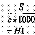

L/C H1/H2 H1≦H2 130≦L/C 300≦L/C ≦2000 750≦L≦ 1450 260 ≦d≦ 550 Heat increase (ΔT) Heat dissipating time (min) Primary resonance peak (Hz) Vibration damping ratio (%) Example 1 0.8 13.3 50 0.1 ○ × × × × 26 20 200 35 Example 2 3.8 13.3 250 0.3 ○ ○ × × × 24 20 190 33 Example 3 7.5 13,3 500 0.6 ○ × ○ × × 22 19 185 31 Example 4 37.5 13.3 2500 2.8 × ○ × × × 20 19 183 30 Example 5 0.8 10.0 35 0.1 ○ × × × × 24 19 190 38 Example 6 1.5 10.0 70 0.2 ○ × × × × 22 19 188 35 Example 7 7.5 10.0 350 0.8 ○ ○ ○ × × 21 18 185 33 Example 8 15.0 10.0 700 1.5 × ○ ○ × × 20 18 182 31 Example 9 1.0 6.7 33 0.2 ○ × × × × 22 19 185 39 Example 10 1.5 6.7 50 0.2 ○ × × × × 22 18 183 38 Example11 3.0 6.7 100 0.5 ○ × × × × 21 17 181 37 Example 12 15.0 6.7 500 2.3 × ○ ○ × × 20 17 180 37 Example13 2.0 5.0 47 0.4 ○ × × ○ × 20 18 179 41 Example14 3.0 5.0 70 0.6 ○ × × ○ × 19 16 175 39 Example15 6.0 5.0 140 1.2 × ○ × ○ × 8 16 173 38 Example 16 3.0 3.3 50 0.9 ○ × × ○ ○ 25 18 150 43 Example 17 4.0 3.3 67 1.2 ○ × × ○ ○ 24 16 148 41 Example 18 6.0 3.3 100 1.8 × × × ○ ○ 20 15 145 39 Example 19 2.0 2.5 23.33333 0.8 ○ × × ○ ○ 25 18 135 42 Example 20 2.4 2.5 28 1.0 ○ × × ○ ○ 23 17 133 41 Example 21 3.0 2.5 35 1.2 × × × ○ ○ 23 17 131 39 Example22 1.2 1.7 10 0.7 ○ × × × × 25 19 125 42 Example 23 1.6 1.7 13.33333 1.0 ○ × × × × 24 18 123 42 Example 24 2.4 1.7 20 1.4 × × × × × 24 18 123 41 Comparative Example 1 0.8 13.3 50 0.1 ○ × × × × 27 60≤ 95 Standard Comparative Example2 37.5 13.3 2500 2.8 × ○ × × × 25 30 98 -10 Comparative Example 3 0.8 10.0 35 0.1 ○ × × × × 25 60 ≤ 88 Standard Comparative Example4 15.0 10.0 700 1.5 × ○ ○ × × 24 30 90 -7 Comparative Example5 1.0 6.7 33 0.2 ○ × × × × 23 60 ≤ 80 Standard Comparative Example 6 15.0 6.7 500 2.3 × ○ ○ × × 24 40 85 -7 Comparative Example 7 2.0 5.0 47 0.4 ○ × × ○ × 25 60≤ 85 Standard Comparative Example8 6.0 5.0 140 1.2 × ○ × ○ × 24 45 95 -8 Comparative Example9 3.0 3.3 50 0.9 ○ × × ○ ○ 30 60≤ 78 Standard Comparative Example 10 6.0 3.3 100 1.8 × × × ○ ○ 28 45 80 -8 Comparative Example 11 2.0 2.5 23.33333 0.8 ○ × × ○ ○ 35 60≤ 75 Standard Comparative Example 12 3.0 2.5 35 1.2 × × × ○ ○ 34 60 ≤ 80 -9 Comparative Example 13 1.2 1.7 10 0.7 ○ × × × × 50 60 ≤ 50 Standard Comparative Example 14 2.4 1.7 20 1.4 × × × × × 48 60 ≤ 50 -10 Table 2 Battery structure Number of electrode layers Size Thickness of heat dissipating member (mm) Number of heat dissipating member Material of heat dissipating member Thermal conductivity of heat dissipating member(W/m/K) Longer side a(mm) Shorter side: b(mm) Thickness: c(mm) Outer periphery: L(mm) Area: S(m2) Diagonal line: d(mm) Example 1 Stacking-type laminate 20 About A8 0.05 1 sheet Ceramics 1.5 75 50 5 250 0.00375 90 Example 2 Stacking-type laminate 5 About A8 0.05 1 sheet Ceramics 1.6 75 50 1 250 0.00375 90 Example 3 Stacking-type laminate 3 About A8 0.01 1 sheet Ceramics 1.5 75 50 0.5 250 0.00375 90 Example 4 Stacking-type laminate 2 About A8 0.01 1 sheet Ceramics 1.5 75 50 0.1 250 0.00375 90 Example 5 Stacking-type laminate 40 About A7 0.1 1 sheet Ceramics 1.5 100 75 10 350 0,0075 125 Example 6 Stacking-type laminate 20 About A7 0.01 1 sheet Ceramics 1.5 100 75 5 350 0.0075 125 Example 7 Stacking-type laminate 5 About A7 0.01 1 sheet Ceramics 1.5 100 75 1 350 0.0075 125 Example 8 Stacking-type laminate 3 About A7 0.1 sheet Ceramics 1.5 100 75 0.5 350 0.0075 125 Example 9 Bipolar-type laminate 50 About A6 0.1 1 sheet Carbon steel +Carbon 300 150 100 15 500 0.015 180 Example 10 Bipolar-type laminate 30 About A6 0.1 1 sheet Carbon steel+ Carbon 300 150 100 10 500 0.015 180 Example 11 Bipolar-type laminate 15 About A6 0.1 sheet Carbon steels Carbon 300 150 100 5 500 0.015 180 Example 12 Bipolar-type laminate 4 About A6 0.1 1 sheet Carbon steel+ Carbon 300 150 100 1 500 0.015 180 Example 13 Bipolar-type laminate 50 About A5 0.1 1 sheet Aluminum+ Carbon 200 200 150 15 700 0.03 250 Example 14 Bipolar-type laminate 30 About A5 0.5 1 sheet Aluminum+Carbon 200 200 150 10 700 0.03 250 Example 15 Bipolar-type laminate 15 About A5 0.5 1 sheet Aluminum+ Carbon 200 200 150 5 700 0.03 250 Example 15 Bipolar-type laminate 60 About A4 0.5 1 sheet PE+ Carbon 0.5 300 200 20 1000 0.06 361 Example 16 Bipolar-type laminate 50 About A4 0.1 1 sheet Rubber + Carbon 0.5 300 200 15 1000 0.06 361 Example17 Bipolar-type laminate 30 About A4 0.1 1 sheet Aluminum+Carbon 0.5 300 200 10 1000 0.06 361 Example 18 Bipolar-type laminate 90 About A3 0.5 5 sheet PE+ Carbon 0.5 400 300 60 1400 0:12 500 Example 19 Bipolar-type laminate 80 About A3 0.5 4 sheet PE+ Carbon 0.5 400 300 50 1400 0:12 500 Example 20 Bipolar-type laminate 70 About A3 0.5 3 sheet PE+Carbon 0.5 400 300 40 1400 0.12 500 Example 21 Bipolar-type 200 About A2 0.5 19 sheet PE+Carbon 0.5 600 400 200 2000 0.24 721 Example 22 Bipolar-type 150 About A2 0.5 14 sheet PE+ Carbon 0.5 600 400 150 2000 0.24 721 Example23 Bipolar-type 100 About A2 0.5 9 sheet PE+Carbon 0.5 600 400 100 2000 0.24 721 Comparative Example 1 1 Stacking-type laminate 20 About A8 None None - - 75 50 5 250 0.00375 90 Comparative Example 2 Stacking-type laminate 2 About A8 None None - - 75 50 0.1 250 0.00375 90 Comparative Example 3 Stacking-type laminate 40 About A7 None None - - 100 75 10 350 0.0075 125 Comparative Example 4 Stacking-type laminate 3 About A7 None None - - 100 75 0.5 350 0.0075 125 Comparative Example 5 Bipolar-type laminate 50 About A6 None None - - 150 100 15 500 0.015 180 Comparative Example 6 Bipolar-type laminate 4 About A6 None None - - 150 100 1 500 0.015 180 Comparative Example 7 Bipolar-type laminate 50 About A5 None None - - 200 150 15 700 0.03 250 Comparative Example 8 Bipolar-type laminate 15 About A5 None None - - 200 150 5 700 0.03 250 Comparative Example 9 Bipolar-type laminate 60 About A4 None None - - 300 200 20 1000 0.06 361 Comparative Example10 Bipolar-type laminate 30 About A4 None None - - 300 200 10 1000 0.06 361 Comparative Example 1 Bipolar-type laminate 90 About A3 None None - - 400 300 60 1400 0.12 500 Comparative Example12 Bipolar-type laminate 70 About A3 None None - - 400 300 40 1400 0.12 500 Comparative Example13 Bipolar-type 200 AboutA2 None None - - 600 400 200 2000 0.24 721 Comparative Example14 Bipolar-type 100 AboutA2 None None - - 600 400 100 2000 0.24 721 - The present invention is useful for a battery structure requiring high power, high capacity and/or high durability.
- The above-described embodiments have been described in order to allow easy understanding of the invention and do not limit the invention. On the contrary, the invention is intended to cover various modifications and equivalent arrangements included within the scope of the appended claims, which scope is to be accorded the broadest interpretation so as to encompass all such modifications and equivalent structure as is permitted under the law.
- This application claims priority from
Japanese Patent Application No. JP2006-140969, filed 20th May 2006
Claims (15)
- A battery structure, comprising:a plurality of unit cell layers, each unit cell layer comprising a cathode active material layer formed on a surface of one collector, a separator for retaining an electrolyte and an anode active material layer formed on a surface of another collector; anda heat dissipating member disposed between at least one unit cell layer and another unit cell layer.
- A battery structure as claimed in claim 1, wherein the heat dissipating member is arranged to absorb a vibration transmitted from an outside.
- A battery structure as claimed in claim 1 or claim 2 comprising a covering material for covering the battery structure, wherein the covering material is in contact with a part of the heat dissipating member.
- A battery structure as claimed in any preceding claim wherein the battery structure meets the following formula S/c ≤ b/S wherein b is a length of a shorter side of a cathode active material contact area of the cathode active material layer and the collector or a length of a shorter side of an anode active material contact area of the anode active material layer and the collector, S is an area of the cathode active material contact area or the anode active material contact area, and c is defined as a thickness of the battery structure excluding the heat dissipating member.
- A battery structure as claimed in claim 4 wherein a length of an outer periphery of the cathode active material contact area or a length of an outer periphery of the anode active material contact area is equal to or greater than 130 times of the thickness of the battery structure excluding the heat dissipating member.
- A battery structure as claimed in any preceding claim, wherein a thermal conductivity of the heat dissipating member is 0.1 to 450 W/m•k.
- A battery structure as claimed in any preceding claim, wherein the heat dissipating member comprises a vibration absorbing material dispersed into base materials having a heat dissipating property.
- A battery structure as claimed in any preceding claim, wherein a Shore A hardness of a separator of a first unit cell layer among the plurality of unit cell layers differs from a Shore A hardness of a separator of another unit cell layer.
- A battery structure as claimed in any preceding claim, wherein the separator comprises at least one resin selected from the group consisting of a polyester-based resin, an aramid-based resin and a polypropylene-based resin.
- A battery structure as claimed in any preceding claim, wherein the cathode active material comprises at least one of Li-Mn based composite oxide and Li-Ni based composite oxide.
- A battery structure as claimed in any preceding claim, wherein the anode active material comprises at least one of a crystalline carbon material and a non-crystalline carbon material.
- A battery structure as claimed in any preceding claim wherein the heat dissipating member is disposed at an uppermost or a lowermost surface of the at least one unit cell layer at a side opposed from the another unit cell layer.
- A battery assembly comprising a plurality of battery structures as claimed in any preceding claim, wherein the plurality of battery structures are connected in series or in parallel or in a combination of in series and in parallel.
- A vehicle having a battery structure or a battery assembly as claimed in any preceding claim.
- A method of making a battery structure, comprising:alternately stacking a cathode active material layer formed on a surface of one collector, a separator for retaining an electrolyte, and an anode active material layer formed on a surface of second collector to form a first unit cell layer;alternately stacking a cathode active material layer formed on a surface of a third collector, a separator for retaining an electrolyte, and an anode active material layer formed on a surface of a fourth collector to form a second unit cell layer; anddisposing a heat dissipating member between the first unit cell layer and the second unit cell layer.
Applications Claiming Priority (1)
| Application Number | Priority Date | Filing Date | Title |
|---|---|---|---|
| JP2006140969A JP5061502B2 (en) | 2006-05-20 | 2006-05-20 | Battery structure |
Publications (1)
| Publication Number | Publication Date |
|---|---|
| EP1858107A1 true EP1858107A1 (en) | 2007-11-21 |
Family
ID=38475970
Family Applications (1)
| Application Number | Title | Priority Date | Filing Date |
|---|---|---|---|
| EP20070108435 Withdrawn EP1858107A1 (en) | 2006-05-20 | 2007-05-18 | Battery Structure |
Country Status (5)
| Country | Link |
|---|---|
| US (1) | US8304103B2 (en) |
| EP (1) | EP1858107A1 (en) |
| JP (1) | JP5061502B2 (en) |
| KR (1) | KR20070112345A (en) |
| CN (1) | CN101079502B (en) |
Cited By (5)
| Publication number | Priority date | Publication date | Assignee | Title |
|---|---|---|---|---|
| WO2010083982A1 (en) * | 2009-01-23 | 2010-07-29 | Li-Tec Battery Gmbh | Battery cell having a jacket |
| EP2639876A1 (en) * | 2012-03-15 | 2013-09-18 | Kabushiki Kaisha Toshiba | Nonaqueous electrolyte secondary battery |
| EP2406840A4 (en) * | 2009-03-09 | 2017-03-01 | Chun-Chieh Chang | High durability lithium-ion cells |
| CN109830781A (en) * | 2019-01-28 | 2019-05-31 | 天津荣事顺发电子有限公司 | A battery pack heat dissipation and temperature balance device |
| CN114223085A (en) * | 2019-11-19 | 2022-03-22 | 株式会社Lg新能源 | Battery module including thermally conductive resin dispersed with metal particles, and method and system for inspecting the same |
Families Citing this family (58)
| Publication number | Priority date | Publication date | Assignee | Title |
|---|---|---|---|---|
| US8883354B2 (en) | 2006-02-15 | 2014-11-11 | Optodot Corporation | Separators for electrochemical cells |
| KR100810601B1 (en) * | 2006-12-29 | 2008-03-06 | 새한에너테크 주식회사 | Crude cell for large area secondary battery and manufacturing method thereof |
| US8381849B2 (en) * | 2007-03-30 | 2013-02-26 | The Regents Of The University Of Michigan | Vehicle hybrid energy system |
| JP2011503800A (en) * | 2007-11-07 | 2011-01-27 | エナーデル、インク | Battery assembly having temperature control device |
| DE102008041547A1 (en) * | 2008-08-26 | 2010-03-04 | Robert Bosch Gmbh | battery module |
| KR101095346B1 (en) * | 2008-12-12 | 2011-12-16 | 주식회사 엘지화학 | Battery module and medium / large battery pack with excellent heat dissipation |
| JP5381078B2 (en) * | 2008-12-19 | 2014-01-08 | 日産自動車株式会社 | Electrode and manufacturing method thereof |
| WO2010138177A1 (en) | 2009-05-26 | 2010-12-02 | Steven Allen Carlson | Lithium batteries utilizing nanoporous separator layers |
| US9065159B2 (en) * | 2009-05-26 | 2015-06-23 | The Invention Science Fund I, Llc | System and method of altering temperature of an electrical energy storage device or an electrochemical energy generation device using microchannels |
| CN102460769A (en) * | 2009-06-05 | 2012-05-16 | K2能源解决方案公司 | Lithium ion battery pack having cathode and anode current collectors |
| EP2273162B1 (en) * | 2009-07-06 | 2019-01-09 | Carl Freudenberg KG | Sealing frame for use in a battery |
| JP5556128B2 (en) * | 2009-10-30 | 2014-07-23 | ソニー株式会社 | Non-aqueous electrolyte battery |
| KR101093890B1 (en) * | 2010-01-12 | 2011-12-13 | 삼성에스디아이 주식회사 | Secondary battery |
| US9450266B2 (en) | 2010-05-19 | 2016-09-20 | Nissan Motor Co., Ltd. | Bipolar secondary battery |
| US20110293984A1 (en) * | 2010-05-28 | 2011-12-01 | Gm Global Technology Operations, Inc. | Enhanced high voltage terminal cooling with a high thermal conductivity coating |
| CN106784556A (en) | 2010-07-19 | 2017-05-31 | 奥普图多特公司 | For the barrier film of electrochemical cell |
| DE102010062858B4 (en) | 2010-12-10 | 2023-06-01 | Robert Bosch Gmbh | battery cell |
| JP5804323B2 (en) | 2011-01-07 | 2015-11-04 | 株式会社Gsユアサ | Power storage element and power storage device |
| US8628874B2 (en) * | 2011-01-28 | 2014-01-14 | Samsung Sdi Co., Ltd. | Secondary battery |
| JP2012186034A (en) * | 2011-03-07 | 2012-09-27 | Toyota Industries Corp | Laminate battery |
| DE102011013618A1 (en) * | 2011-03-11 | 2012-09-13 | Li-Tec Battery Gmbh | Energy storage device |
| JP2012221580A (en) | 2011-04-04 | 2012-11-12 | Toyota Motor Corp | Solid-state battery |
| WO2012149467A1 (en) * | 2011-04-29 | 2012-11-01 | G4 Synergetics, Inc. | Stacking and sealing configurations for energy storage devices |
| JP5994354B2 (en) * | 2011-09-05 | 2016-09-21 | ソニー株式会社 | Separator and nonaqueous electrolyte battery, battery pack, electronic device, electric vehicle, power storage device, and power system |
| CN103165952A (en) * | 2011-12-09 | 2013-06-19 | 乐荣工业股份有限公司 | Lithium battery cells that can conduct heat directly from the inside to the outside for heat dissipation |
| JP5918019B2 (en) * | 2012-05-18 | 2016-05-18 | 株式会社オハラ | All solid state secondary battery |
| KR101571774B1 (en) * | 2012-06-12 | 2015-11-25 | 주식회사 엘지화학 | Battery Cell of Improved Cooling Efficiency |
| JP5964951B2 (en) * | 2012-07-30 | 2016-08-03 | 帝人株式会社 | Nonaqueous electrolyte battery separator and nonaqueous electrolyte battery |
| JP6020920B2 (en) * | 2013-04-09 | 2016-11-02 | 株式会社デンソー | Electricity storage element |
| KR102236436B1 (en) | 2013-04-29 | 2021-04-06 | 옵토도트 코포레이션 | Nanoporous composite separators with increased thermal conductivity |
| US9312571B2 (en) * | 2014-03-19 | 2016-04-12 | Ford Global Technologies, Llc | Traction battery thermal plate with flexible bladder |
| JP6237479B2 (en) * | 2014-06-05 | 2017-11-29 | 株式会社豊田自動織機 | Battery module and battery pack |
| US12040506B2 (en) | 2015-04-15 | 2024-07-16 | Lg Energy Solution, Ltd. | Nanoporous separators for batteries and related manufacturing methods |
| US10381623B2 (en) | 2015-07-09 | 2019-08-13 | Optodot Corporation | Nanoporous separators for batteries and related manufacturing methods |
| GB2543827A (en) * | 2015-10-30 | 2017-05-03 | Sharp Kk | Metal ion battery current collector |
| KR102553087B1 (en) * | 2015-12-21 | 2023-07-06 | 에스케이온 주식회사 | Lithium secondary battery |
| US11374291B2 (en) * | 2016-05-27 | 2022-06-28 | Panasonic Holdings Corporation | Secondary cell |
| CN109314281B (en) * | 2016-09-28 | 2021-06-08 | 株式会社日立制作所 | All solid state battery |
| JP6620944B2 (en) * | 2016-11-28 | 2019-12-18 | トヨタ自動車株式会社 | Laminated battery and battery pack for series connection |
| KR102322289B1 (en) * | 2017-01-03 | 2021-11-05 | 현대자동차주식회사 | Heat releasing composite, the aluminium pouch film comprising the same, and the water cooling system using the same |
| KR102630853B1 (en) | 2017-08-29 | 2024-01-30 | 주식회사 엘지에너지솔루션 | Pouch-Type Secondary Battery Having Heat Transfer Member |
| DE102017008102A1 (en) | 2017-08-29 | 2019-02-28 | Carl Freudenberg Kg | Energy storage system |
| JP6893457B2 (en) * | 2017-09-13 | 2021-06-23 | 本田技研工業株式会社 | Current collector plate arrangement structure of bipolar solid-state battery |
| JP6948258B2 (en) * | 2017-12-28 | 2021-10-13 | 株式会社豊田自動織機 | Power storage module and its manufacturing method |
| US11226488B2 (en) * | 2018-03-21 | 2022-01-18 | Nippon Seiki Co., Ltd. | Head-up display |
| JP2020095863A (en) * | 2018-12-13 | 2020-06-18 | トヨタ紡織株式会社 | Secondary battery |
| JP7356079B2 (en) * | 2019-08-28 | 2023-10-04 | トヨタ紡織株式会社 | battery system |
| EP4254589A4 (en) * | 2020-11-24 | 2025-07-16 | Toyota Jidoshokki Kk | POWER STORAGE DEVICE |
| JP7225193B2 (en) * | 2020-12-25 | 2023-02-20 | プライムプラネットエナジー&ソリューションズ株式会社 | Battery module and manufacturing method thereof |
| CN112864474B (en) * | 2021-01-05 | 2022-10-11 | 国联汽车动力电池研究院有限责任公司 | High-safety battery structure and battery |
| BR112023022296A2 (en) | 2021-04-29 | 2023-12-26 | 24M Tech Inc | ELECTROCHEMICAL CELLS WITH MULTIPLE SEPARATORS, AND PRODUCTION METHODS THEREOF |
| US20240097266A1 (en) * | 2022-09-15 | 2024-03-21 | GM Global Technology Operations LLC | Battery assembly and method therefor |
| KR20240047080A (en) * | 2022-10-04 | 2024-04-12 | 주식회사 엘지에너지솔루션 | Battery cell wherein heat propagation is prevented |
| TW202443944A (en) | 2022-12-16 | 2024-11-01 | 美商24M科技公司 | Systems and methods for minimizing and preventing dendrite formation in electrochemical cells |
| JP7818548B2 (en) * | 2023-05-01 | 2026-02-20 | プライムプラネットエナジー&ソリューションズ株式会社 | Non-aqueous electrolyte secondary battery and battery pack |
| DE102023206613A1 (en) * | 2023-07-12 | 2025-01-16 | Volkswagen Aktiengesellschaft | battery cell |
| JP2025068934A (en) * | 2023-10-17 | 2025-04-30 | トヨタ自動車株式会社 | Battery Module |
| US12431545B1 (en) | 2024-03-26 | 2025-09-30 | 24M Technologies, Inc. | Systems and methods for minimizing and preventing dendrite formation in electrochemical cells |
Citations (4)
| Publication number | Priority date | Publication date | Assignee | Title |
|---|---|---|---|---|
| WO1989010011A1 (en) * | 1988-04-11 | 1989-10-19 | Ove Nilsson | Means for heat battery management of batteries and lead acid battery with this means |
| EP0522981A1 (en) * | 1991-06-28 | 1993-01-13 | Sorapec S.A. | Monobloc accumulator battery |
| EP0613204A1 (en) * | 1993-02-08 | 1994-08-31 | Globe-Union Inc. | Thermal management of rechargeable batteries |
| US20060090492A1 (en) * | 2004-10-26 | 2006-05-04 | Jaesung Ahn | Cooling system for battery pack |
Family Cites Families (15)
| Publication number | Priority date | Publication date | Assignee | Title |
|---|---|---|---|---|
| US4080728A (en) * | 1974-08-08 | 1978-03-28 | Polaroid Corporation | Method of making flat battery |
| US4042760A (en) * | 1975-04-02 | 1977-08-16 | Polaroid Corporation | Flat battery |
| FR2752088B1 (en) * | 1996-08-05 | 1998-09-04 | Accumulateurs Fixes | WATERPROOF MONOBLOCK BATTERY |
| JPH11130900A (en) * | 1997-10-27 | 1999-05-18 | Asahi Chem Ind Co Ltd | Finely porous polyethylene membrane |
| US5958088A (en) * | 1998-03-04 | 1999-09-28 | Duracell, Inc. | Prismatic cell construction |
| JP2000100471A (en) | 1998-09-22 | 2000-04-07 | Mitsubishi Cable Ind Ltd | Sheet battery |
| JP2000195495A (en) | 1998-12-25 | 2000-07-14 | Mitsubishi Cable Ind Ltd | Sheet battery |
| JP4361229B2 (en) * | 2001-07-04 | 2009-11-11 | 日産自動車株式会社 | Battery system |
| JP4707923B2 (en) * | 2002-06-17 | 2011-06-22 | パナソニック株式会社 | Assembled battery |
| JP4374947B2 (en) * | 2003-08-25 | 2009-12-02 | 日産自動車株式会社 | Multilayer bipolar secondary battery having a cooling tab |
| JP4300310B2 (en) * | 2003-11-13 | 2009-07-22 | 日産自動車株式会社 | Bipolar battery, assembled battery, composite assembled battery, and vehicle using assembled battery or composite assembled battery |
| CN2702452Y (en) * | 2003-11-27 | 2005-05-25 | 王文宏 | Flat-type lithium ion polymer power battery |
| JP4367235B2 (en) * | 2004-05-28 | 2009-11-18 | 日産自動車株式会社 | Bipolar battery, battery pack, and vehicle equipped with the same |
| JP5082227B2 (en) * | 2004-11-22 | 2012-11-28 | 日産自動車株式会社 | Battery structure |
| JP4923679B2 (en) * | 2006-03-31 | 2012-04-25 | トヨタ自動車株式会社 | Stacked battery |
-
2006
- 2006-05-20 JP JP2006140969A patent/JP5061502B2/en not_active Expired - Fee Related
-
2007
- 2007-05-17 US US11/750,005 patent/US8304103B2/en not_active Expired - Fee Related
- 2007-05-18 KR KR1020070048642A patent/KR20070112345A/en not_active Abandoned
- 2007-05-18 EP EP20070108435 patent/EP1858107A1/en not_active Withdrawn
- 2007-05-21 CN CN2007101041583A patent/CN101079502B/en not_active Expired - Fee Related
Patent Citations (4)
| Publication number | Priority date | Publication date | Assignee | Title |
|---|---|---|---|---|
| WO1989010011A1 (en) * | 1988-04-11 | 1989-10-19 | Ove Nilsson | Means for heat battery management of batteries and lead acid battery with this means |
| EP0522981A1 (en) * | 1991-06-28 | 1993-01-13 | Sorapec S.A. | Monobloc accumulator battery |
| EP0613204A1 (en) * | 1993-02-08 | 1994-08-31 | Globe-Union Inc. | Thermal management of rechargeable batteries |
| US20060090492A1 (en) * | 2004-10-26 | 2006-05-04 | Jaesung Ahn | Cooling system for battery pack |
Cited By (7)
| Publication number | Priority date | Publication date | Assignee | Title |
|---|---|---|---|---|
| WO2010083982A1 (en) * | 2009-01-23 | 2010-07-29 | Li-Tec Battery Gmbh | Battery cell having a jacket |
| EP2406840A4 (en) * | 2009-03-09 | 2017-03-01 | Chun-Chieh Chang | High durability lithium-ion cells |
| EP2639876A1 (en) * | 2012-03-15 | 2013-09-18 | Kabushiki Kaisha Toshiba | Nonaqueous electrolyte secondary battery |
| US9017861B2 (en) | 2012-03-15 | 2015-04-28 | Kabushiki Kaisha Toshiba | Nonaqueous electrolyte secondary battery |
| CN109830781A (en) * | 2019-01-28 | 2019-05-31 | 天津荣事顺发电子有限公司 | A battery pack heat dissipation and temperature balance device |
| CN114223085A (en) * | 2019-11-19 | 2022-03-22 | 株式会社Lg新能源 | Battery module including thermally conductive resin dispersed with metal particles, and method and system for inspecting the same |
| US12355044B2 (en) | 2019-11-19 | 2025-07-08 | Lg Energy Solution, Ltd. | Battery module comprising metal particle-dispersed thermal conductive resin and method and system for inspecting same |
Also Published As
| Publication number | Publication date |
|---|---|
| US20070269714A1 (en) | 2007-11-22 |
| US8304103B2 (en) | 2012-11-06 |
| JP2007311264A (en) | 2007-11-29 |
| CN101079502B (en) | 2010-06-02 |
| KR20070112345A (en) | 2007-11-23 |
| JP5061502B2 (en) | 2012-10-31 |
| CN101079502A (en) | 2007-11-28 |
Similar Documents
| Publication | Publication Date | Title |
|---|---|---|
| US8304103B2 (en) | Battery structure | |
| EP1986250B1 (en) | Cell module, battery pack and vehicle with such batteries mounted thereon | |
| EP1953861B1 (en) | Cell structure, battery and vehicle mounted with those | |
| EP2250689B1 (en) | Battery with battery electrode and method of manufacturing same | |
| EP1487034B1 (en) | Bipolar battery and related method | |
| US7501206B2 (en) | Bipolar battery, assembled battery, combination assembled battery, and vehicle using the assembled battery or the combination assembled battery | |
| EP1928050B1 (en) | Bipolar Battery and Battery Assembly | |
| EP2408045A1 (en) | Bipolar battery current collector and bipolar battery | |
| JP5082227B2 (en) | Battery structure | |
| JP2005149891A (en) | Bipolar battery and assembled battery using the same | |
| US8124265B2 (en) | Power storage device | |
| JP2005174691A (en) | Bipolar battery | |
| JP4367235B2 (en) | Bipolar battery, battery pack, and vehicle equipped with the same | |
| JP4466088B2 (en) | Assembled battery | |
| JP4635589B2 (en) | Bipolar battery, assembled battery, composite battery and vehicle equipped with these | |
| CN100431201C (en) | battery structure | |
| JP4984388B2 (en) | Bipolar battery, assembled battery, composite battery and vehicle equipped with these | |
| JP2010251017A (en) | Bipolar secondary battery, assembled battery and vehicle using the bipolar secondary battery |
Legal Events
| Date | Code | Title | Description |
|---|---|---|---|
| PUAI | Public reference made under article 153(3) epc to a published international application that has entered the european phase |
Free format text: ORIGINAL CODE: 0009012 |
|
| AK | Designated contracting states |
Kind code of ref document: A1 Designated state(s): AT BE BG CH CY CZ DE DK EE ES FI FR GB GR HU IE IS IT LI LT LU LV MC MT NL PL PT RO SE SI SK TR |
|
| AX | Request for extension of the european patent |
Extension state: AL BA HR MK YU |
|
| 17P | Request for examination filed |
Effective date: 20080521 |
|
| AKX | Designation fees paid |
Designated state(s): DE FR GB |
|
| 17Q | First examination report despatched |
Effective date: 20080708 |
|
| RIC1 | Information provided on ipc code assigned before grant |
Ipc: H01M 10/6555 20140101ALI20160303BHEP Ipc: H01M 10/0525 20100101AFI20160303BHEP Ipc: H01M 10/0585 20100101ALI20160303BHEP Ipc: H01M 10/04 20060101ALI20160303BHEP Ipc: H01M 10/613 20140101ALI20160303BHEP |
|
| GRAP | Despatch of communication of intention to grant a patent |
Free format text: ORIGINAL CODE: EPIDOSNIGR1 |
|
| RIC1 | Information provided on ipc code assigned before grant |
Ipc: H01M 10/613 20140101ALI20160310BHEP Ipc: H01M 10/0525 20100101ALN20160310BHEP Ipc: H01M 10/0585 20100101ALI20160310BHEP Ipc: H01M 10/6555 20140101AFI20160310BHEP Ipc: H01M 10/04 20060101ALI20160310BHEP |
|
| RAP1 | Party data changed (applicant data changed or rights of an application transferred) |
Owner name: NISSAN MOTOR CO., LTD. |
|
| RIN1 | Information on inventor provided before grant (corrected) |
Inventor name: HORIE, HIDEAKI Inventor name: HOSAKA, KENJI Inventor name: WATANABE, KYOICHI Inventor name: SATO, HAJIME |
|
| INTG | Intention to grant announced |
Effective date: 20160408 |
|
| STAA | Information on the status of an ep patent application or granted ep patent |
Free format text: STATUS: THE APPLICATION IS DEEMED TO BE WITHDRAWN |
|
| 18D | Application deemed to be withdrawn |
Effective date: 20160819 |