EP1856470B1 - Detection et suivi d'objets dans des images - Google Patents
Detection et suivi d'objets dans des images Download PDFInfo
- Publication number
- EP1856470B1 EP1856470B1 EP06717487A EP06717487A EP1856470B1 EP 1856470 B1 EP1856470 B1 EP 1856470B1 EP 06717487 A EP06717487 A EP 06717487A EP 06717487 A EP06717487 A EP 06717487A EP 1856470 B1 EP1856470 B1 EP 1856470B1
- Authority
- EP
- European Patent Office
- Prior art keywords
- image
- equation
- model
- training
- eigenspace
- Prior art date
- Legal status (The legal status is an assumption and is not a legal conclusion. Google has not performed a legal analysis and makes no representation as to the accuracy of the status listed.)
- Active
Links
- 238000012549 training Methods 0.000 claims description 203
- 238000000034 method Methods 0.000 claims description 106
- 238000012545 processing Methods 0.000 claims description 23
- 238000000513 principal component analysis Methods 0.000 claims description 8
- 238000004590 computer program Methods 0.000 claims 1
- 230000008569 process Effects 0.000 description 43
- 239000011159 matrix material Substances 0.000 description 35
- 230000006870 function Effects 0.000 description 17
- 238000005070 sampling Methods 0.000 description 15
- 238000001514 detection method Methods 0.000 description 6
- 230000005855 radiation Effects 0.000 description 5
- 238000005516 engineering process Methods 0.000 description 3
- 230000001747 exhibiting effect Effects 0.000 description 3
- 238000012546 transfer Methods 0.000 description 3
- 241000282412 Homo Species 0.000 description 2
- 230000001174 ascending effect Effects 0.000 description 2
- 238000010586 diagram Methods 0.000 description 2
- 239000010432 diamond Substances 0.000 description 2
- 230000000694 effects Effects 0.000 description 2
- 230000003993 interaction Effects 0.000 description 2
- 230000003278 mimic effect Effects 0.000 description 2
- 238000012935 Averaging Methods 0.000 description 1
- 238000004891 communication Methods 0.000 description 1
- 230000001419 dependent effect Effects 0.000 description 1
- 230000005670 electromagnetic radiation Effects 0.000 description 1
- 238000001914 filtration Methods 0.000 description 1
- 238000005286 illumination Methods 0.000 description 1
- 238000003384 imaging method Methods 0.000 description 1
- 238000002955 isolation Methods 0.000 description 1
- 230000007246 mechanism Effects 0.000 description 1
- 238000012986 modification Methods 0.000 description 1
- 230000004048 modification Effects 0.000 description 1
- 238000005457 optimization Methods 0.000 description 1
- 230000008520 organization Effects 0.000 description 1
- 238000003909 pattern recognition Methods 0.000 description 1
- 230000000007 visual effect Effects 0.000 description 1
Images


Classifications
-
- G—PHYSICS
- G06—COMPUTING; CALCULATING OR COUNTING
- G06V—IMAGE OR VIDEO RECOGNITION OR UNDERSTANDING
- G06V40/00—Recognition of biometric, human-related or animal-related patterns in image or video data
- G06V40/10—Human or animal bodies, e.g. vehicle occupants or pedestrians; Body parts, e.g. hands
- G06V40/107—Static hand or arm
-
- G—PHYSICS
- G06—COMPUTING; CALCULATING OR COUNTING
- G06F—ELECTRIC DIGITAL DATA PROCESSING
- G06F18/00—Pattern recognition
- G06F18/20—Analysing
- G06F18/21—Design or setup of recognition systems or techniques; Extraction of features in feature space; Blind source separation
- G06F18/213—Feature extraction, e.g. by transforming the feature space; Summarisation; Mappings, e.g. subspace methods
- G06F18/2135—Feature extraction, e.g. by transforming the feature space; Summarisation; Mappings, e.g. subspace methods based on approximation criteria, e.g. principal component analysis
-
- G—PHYSICS
- G06—COMPUTING; CALCULATING OR COUNTING
- G06F—ELECTRIC DIGITAL DATA PROCESSING
- G06F18/00—Pattern recognition
- G06F18/20—Analysing
- G06F18/24—Classification techniques
- G06F18/241—Classification techniques relating to the classification model, e.g. parametric or non-parametric approaches
- G06F18/2413—Classification techniques relating to the classification model, e.g. parametric or non-parametric approaches based on distances to training or reference patterns
-
- G—PHYSICS
- G06—COMPUTING; CALCULATING OR COUNTING
- G06V—IMAGE OR VIDEO RECOGNITION OR UNDERSTANDING
- G06V10/00—Arrangements for image or video recognition or understanding
- G06V10/70—Arrangements for image or video recognition or understanding using pattern recognition or machine learning
- G06V10/764—Arrangements for image or video recognition or understanding using pattern recognition or machine learning using classification, e.g. of video objects
-
- G—PHYSICS
- G06—COMPUTING; CALCULATING OR COUNTING
- G06V—IMAGE OR VIDEO RECOGNITION OR UNDERSTANDING
- G06V10/00—Arrangements for image or video recognition or understanding
- G06V10/70—Arrangements for image or video recognition or understanding using pattern recognition or machine learning
- G06V10/77—Processing image or video features in feature spaces; using data integration or data reduction, e.g. principal component analysis [PCA] or independent component analysis [ICA] or self-organising maps [SOM]; Blind source separation
- G06V10/7715—Feature extraction, e.g. by transforming the feature space, e.g. multi-dimensional scaling [MDS]; Mappings, e.g. subspace methods
-
- G—PHYSICS
- G06—COMPUTING; CALCULATING OR COUNTING
- G06V—IMAGE OR VIDEO RECOGNITION OR UNDERSTANDING
- G06V40/00—Recognition of biometric, human-related or animal-related patterns in image or video data
- G06V40/20—Movements or behaviour, e.g. gesture recognition
- G06V40/28—Recognition of hand or arm movements, e.g. recognition of deaf sign language
Definitions
- This disclosure relates to image processing, and, more particularly, to detecting an object in an image.
- PCA Principal Component Analysis
- PCA uses the eigenvalues and eigenvectors of the covariance matrix of a set of data as representative of valuable features of the set of data, thereby reducing the dimensionality of the set of data.
- Computer vision technologies may allow a computer to detect an object within an image captured by a camera.
- a computer that is capable of detecting and recognizing an object within an image may provide a user with the ability to interact with the computer through the use of hand gestures.
- a computer-user interface may be displayed on a surface or screen.
- One or more cameras may monitor activity in the vicinity of the surface or screen and capture images of the activity in the vicinity of the screen.
- the computer may then process these images, detect one or more objects within the images, and perceive that a user is using hand gestures to interact with the computer-user interface displayed on the surface or screen.
- Some systems attempt to perceive that a user is using hand gestures to interact with the computer-user interface displayed on the surface or screen. Some of these systems simply perceive the brightest object in an image and classify that object as a hand or finger. Consequently, these systems may perceive an object as a hand or finger even though the object is neither a hand nor a finger.
- U.S. Patent No. 5,164,992 discloses a recognition system for identifying members of an audience, the system including an imaging system which generates an image of the audience; a selector module for selecting a portion of the generated image; a detection means which analyzes the selected image portion to determine whether an image of a person is present; and a recognition module responsive to the detection means for determining whether a detected image of a person identified by the detection means resembles one of a reference set of images of individuals.
- the invention relates to a computer-implemented method according to claim 1 and a system according to claim 9. Preferred embodiments are described in the dependent claims.
- Images are processed in order to detect the presence of a finger and to track the position of the detected finger.
- the position of a finger may be used by a computer, for example, to control the computer's mouse pointer.
- the methods presented may be useful for allowing humans to interact with computers in a more natural way than through the use of a conventional mouse and/or keyboard.
- a model of one or more fingers positioned! in one or more orientations is created.
- a set of training images of one or more fingers is captured by a camera.
- a model of the set of training images is created.
- the covariance matrix of the set of training images is determined and a select number of eigenvectors of the covariance matrix is selected to define an eigenspace for the set of training images.
- Each of the images of the set of training images is projected into the eigenspace defined by the selected eigenvectors of the covariance matrix.
- each training image is represented by a single training point. Therefore, projecting each training image into the eigenspace creates a cloud of training points in the eigenspace.
- the cloud of training points is then modeled by a geometric model (e.g., surface or line) in the eigenspace.
- the model is then used to detect, recognize, and track fingers within an image.
- a camera and an infrared (IR) illuminator are placed behind the surface or screen.
- a finger touching or moving near the surface or screen reflects some of the IR radiation projected by the IR illuminator.
- Part of the reflected IR radiation is captured in an image by the camera.
- the image is then processed, as explained below, to detect and recognize the presence and position of the finger within the image.
- the processing includes extracting from the image one or more objects that potentially may be fingers.
- Each extracted object is projected into the eigenspace that was defined for the set of training images.
- the projection of the extracted object is represented by a single image point.
- the coordinates of the single image point are compared to the model of the cloud of training points to determine whether the single image point matches, or nearly matches, the model. If the single image point matches, or nearly matches, the model, the object is determined to be a finger. If the object is determined to be a finger, the position of the finger with respect to the screen or surface (for example, an (x,y) coordinate) is calculated and entered into, for example, the computer and/or software application.
- coordinates for an image point in a multi-dimensional space are determined, the image point characterizing a particular object.
- An equation describing a model in the multi-dimensional space is provided, the model being characteristic of a set of training images of one or more other objects.
- the coordinates are applied to the equation to determine a distance between the image point and the model, and a determination is made as to whether the particular object matches the one or more other objects based on the determined distance.
- Implementations of the above general aspect may include one or more of the following features.
- an image of the particular object may be received.
- the image may have a number of data elements
- the multi-dimensional space may have a dimensionality that is lower than the number of data elements.
- Determining the coordinates for the image point may include projecting the image into the multi-dimensional space to produce the coordinates for the image point in the multi-dimensional space.
- the model may be a model of a set of training points in the multi-dimensional space, each of the training points in the set corresponding to one or more images in the sequence of training images.
- the image of the particular object may be normalized before being received. Normalizing the image of the particular object may account for variations in brightness. Normalizing the image of the object may include applying a histogram equalization technique to the image of the particular object.
- the equation describes a hyperboloid or a combination of a cone and a line.
- the particular object is a finger.
- Providing the equation may include selecting the equation from among a first equation and a second equation, the first equation describing a first model characteristic of a first set of training images, and the second equation describing a second model characteristic of a second set of training images.
- an image of a particular object is received, the image having a number of data points.
- the image is projected into a multi-dimensional space having a dimensionality that is lower than the number of data points to produce coordinates for an image point in the multi-dimensional space, where the image point characterizes the particular object.
- An equation describing a model in the multi-dimensional space is provided, the model being a model for a set of training points in the multi-dimensional space, and each of the training points in the set corresponding to one or more images in a training set of images of one or more other objects.
- the coordinates are applied to the equation to determine a distance between the image point and the model and a determination is made as to whether the particular object matches the other objects based on the determined distance.
- Implementations of the above general aspect may include one or more of the following features.
- providing the equation may include selecting the equation from among a first equation and a second equation, where the first equation describes a first model characteristic of a first set of training images, and the second equation describes a second model characteristic of a second set of training images.
- a system includes a camera and a processing device coupled to the camera.
- the processing device is configured to determine coordinates for an image point in a multi-dimensional space, the image point characterizing a particular object.
- the processing device is also configured to provide an equation describing a model in the multi-dimensional space, the model being characteristic of a set of training images of one or more other objects.
- the processing device is further configured to apply the coordinates to the equation to determine a distance between the image point and the model and to determine whether the particular object matches the one or more other objects based on the determined distance.
- the camera may be an IR camera.
- the system may include an IR source.
- the system may include a screen disposed in front of the camera.
- the screen may be at least translucent such that light reflected by an object disposed on a side of the screen opposite the camera can pass through the screen and be received by the camera.
- a tool for determining coordinates for a particular image point in a multi-dimensional space, the particular image point characterizing a particular object.
- the tool also provides an equation describing a model in the multi-dimensional space, the model being characteristic of a set of training images of one or more other objects.
- the tool is also provided for applying the coordinates to the equation to determine a distance between the particular image point and the model, and to determine whether the particular object matches the one or more other objects based on the determined distance.
- Implementations of the above general aspect may include one or more of the following features.
- the set of training images may be received, each of the images in the set having a number of data elements.
- the multi-dimensional space may be determined based on the set of training images and the multi-dimensional space may have a dimensionality that is lower than the number of data elements.
- a set of training points may be generated by projecting each image in the set of training images into the multi-dimensional space to produce coordinates for a corresponding training point in the multi-dimensional space.
- Each training point in the set of training points may correspond to at least one of the images in the set of training images.
- the equation describing the model in the multi-dimensional space characteristic of the set of training images may be determined.
- Each image in the set of training images may be normalized before being received. Normalizing each image in the set of training images may account for variations in brightness. Normalizing each image in the set of training images may include applying a histogram equalization technique to each image in the set of training images.
- the various aspects, implementations, and features may be implemented using, for example, one or more of a method, an apparatus, an apparatus or tool or processing device for performing a method, a program or other set of instructions, an apparatus that includes a program or a set of instructions, and a computer readable medium.
- the computer readable medium may include, for example, instructions, software, images, and other data.
- Systems and methods for detecting and recognizing fingers touching or moving near a surface are disclosed. These systems and methods may also be used to detect and recognize other objects touching or moving near a surface. Furthermore, these systems and methods may also be used to detect and recognize objects in a field of vision absent a surface. More generally, these systems and methods may be used to detect and recognize objects in an image.
- FIG. 1 is an illustration of an exemplary system 100 for recognizing and tracking one or more fingers.
- An infrared (IR) illuminator 102 positioned behind a surface 104 illuminates an area 106 that extends both behind and in front of the surface 104.
- a camera 108 equipped with an IR filter 110 is positioned behind the surface 104 and captures images of, for example, the surface 104 and its vicinity. An image captured by the camera 108 may be represented digitally by data elements (e.g., pixels).
- a projector 112 positioned behind the surface 104 may project a computer-user interface on the surface 104.
- the computer-user interface projected on the surface 104 may be a conventional computer display.
- the projector 112 may project IR in addition to visible light. Therefore, the projector 112 may be equipped with an optional IR filter 120 to reduce or eliminate the IR projected by the projector 112.
- the techniques and apparatus disclosed may allow a user to interact with the computer-user interface using hand gestures.
- the position of a user's finger 114 may be tracked, allowing the user to control the location of the mouse pointer on the computer-user interface by touching the surface 104 with his/her finger 114 or by moving his/her finger 114 near the surface 104.
- the position of the user's finger 114 may be used, for example, to represent the desired location of the mouse pointer.
- the system 100 illustrated in FIG 1 is merely an example of one implementation and other configurations are possible.
- An image captured by the camera 108 may be generated by capturing light reflected by objects.
- Light may include IR, visible light, ultra-violet, or any other form of electromagnetic radiation.
- an IR illuminator 102 may not be required.
- Other light sources may be substituted for the IR illuminator.
- no light source may be required.
- the system 100 may rely solely on reflected ambient light.
- the camera 108 is not required to be positioned behind the surface 104.
- the camera 108 may be positioned anywhere else in the system 100 deemed advantageous.
- the system 100 need not be implemented to facilitate human-computer interaction.
- the system 100 may be used to detect objects within images captured by a camera 108.
- a surface 104 may not be required.
- the system 100 first may be trained to recognize an object as a finger.
- the training stage may involve capturing a set of training images of one or more fingers positioned in one or more orientations and building a model of the set of training images.
- the recognition stage the system 100 may capture an image, extract an object from the captured image, and compare the extracted object to the model of the set of training images generated during the training stage to determine if the extracted object is a finger. Processing that may be involved in detecting and recognizing an object in an image as a finger is described in greater detail below.
- a region of interest (ROI) 116 of an image may be defined as the portion of the image that includes the surface 104.
- the ROI of an image 116 may be examined for the detection and recognition of one or more fingers 114.
- An image captured by the camera 108 may include reflections of the IR generated by the IR illuminator 102 and reflected by one or more fingers within the ROI 116, or the IR may be reflected by one or more other objects within the ROI 116.
- the surface 104 may reflect IR.
- a background model (BGM) of the IR consistently reflected by the surface 104 or other objects within the ROI 116 may be created and subtracted from each image captured by the camera 108. Subtracting the BGM from each image captured by the camera 108 may effectively exclude, or at least reduce, IR attributable to background objects that is processed from a captured image. Consequently, subtracting the BGM from each image may enhance the contrast between an object of interest within the ROI 116 and the surface 104 and/or other objects consistently within the ROI 116.
- the BGM may be updated, for example, randomly, periodically, or upon the occurrence of a triggering event.
- FIGS. 2(a) , 2(b) , and 3 examples of processes for detecting the presence of an object within an image and making an initial determination of whether the object is an object of interest are illustrated.
- FIG 2(a) illustrates two objects 202(a), 204(a) within a sample image 200(a).
- objects 202(a) and 204(a) are shown as darker than the background 206(a).
- the two objects 202(a), 204(a) would be expected to be brighter than the background 206(a).
- the image 200(a) of FIG. 2(a) is merely an example of two objects 202(a), 204(a) in an image 200(a) and that the image 200(a) is not intended to suggest that objects in an image will be darker than the background of the image.
- a blob analysis algorithm such as the Grassfire algorithm
- the Grassfire algorithm is described in, for example, Pitas I., Digital Image Processing Algorithms, Prentice-Hall, New York (1993 ).
- Other algorithms for detecting the presence of an object within an image and extracting the object from the image may be employed.
- the Grassfire algorithm may search an image for objects and identify each pixel of each object it detects with a common label.
- the Grassfire algorithm may determine the brightest pixel in the image.
- the image may be a grayscale image with 256 possible values for each pixel. That is, each pixel may be assigned a value from 0-255 with zero representing the least bright pixel possible (e.g., absolute black) and 255 representing the brightest pixel possible (e.g., absolute white).
- the brightest pixel in the image may have a value of 220.
- the Grassfire algorithm may compare each pixel in the image against an adjustable threshold constant relative to the brightest pixel in the image to determine whether the pixel corresponds to an object.
- the adjustable threshold value may be 50. Therefore, the Grassfire algorithm may consider any pixel in the image within 50 shades of the brightest pixel as representing an object. That is, any pixel with a value within the acceptable range 170-220 may be considered as representing an object. The Grassfire algorithm then may consider any set of adjacent pixels falling within the acceptable range as constituting an object.
- the Grassfire algorithm may produce a matrix called a shadow matrix that is the same size as the original image. Elements of the shadow matrix that correspond to pixels identified as representing an object in the original image may be identified by common labels.
- FIG 2(b) illustrates an example of a shadow matrix 200(b) corresponding to the sample image 200(a) illustrated in FIG 2(a) .
- Object 202(a) in sample image 200(a) is represented by object 202(b) in shadow matrix 200(b) and each element of object 202(b) is identified with a common label "1.”
- object 204(a) in sample image 200(a) is represented by object 204(b) in shadow matrix 200(b) and each element of object 204(b) is identified with a common label "2.”
- the Grassfire algorithm may effectively extract objects 202(a) and 204(a) from sample image 200(a).
- finger 114 would produce the brightest object in an image.
- finger 114 touching the surface 104 or moving near the surface 104 may not always produce the brightest object within an image.
- the user's palm 118 may reflect enough IR radiation to appear as a bright object in an image.
- Other objects such as, for example, a long sleeve, also may reflect enough IR radiation to appear as bright objects in an image.
- Some objects may reflect more IR radiation than the user's finger 114 and consequently may appear as brighter objects in an image than the user's finger 114.
- an extracted object may exhibit features that make it unlikely that it is a finger and therefore may be discarded.
- One criterion that may be used to sort extracted objects may be size. For example, an extracted object may be too large to be a finger. Similarly, an extracted object may be too small to be a finger.
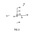
- FIG 3 is a diagram 301 that is used to illustrate an example of a process for determining if an object 300 extracted from an image is too large to be a finger.
- One or more pixels within four sampling areas 304, 306, 308, 310 surrounding the center 302 of an extracted object 300 may be sampled.
- the distance between the center 302 of an extracted object 300 and the sampling areas 304, 306, 308, 310 may be, for example, an adjustable constant.
- two sampling areas 304, 308 surrounding the center 302 of the extracted object 300 may be located on a vertical line 312 passing through the center 302 of the extracted object 300.
- two sampling areas 306, 310 surrounding the center 302 of the extracted object 300 may be located on a horizontal line 314 passing through the center 302 of the extracted object.
- the sampling areas 304, 306, 308, 310 may be considered in pairs.
- the two sampling areas 306, 310 located on the horizontal line 314 passing through the center 302 of the extracted object 300 may be considered as a first pair.
- the two sampling areas 304, 308 located on the vertical line 312 passing through the center 302 of the extracted object 300 may be considered as a second pair.
- the sum of the pixel values within the first pair of sampling areas 306, 310 exceeds an acceptable threshold level, it may be determined that the sampling areas 306, 310 are part of the extracted object 300. If the sum of the pixel values within the first pair of sampling areas 306, 310 exceeds the acceptable threshold level, the sum of the pixel values within the second pair of sampling areas 304, 308 then may be compared to the acceptable threshold level.
- the object may be determined to be too large to be a finger and consequently the object may be discarded.
- objects extracted from an image may be too small to be a finger.
- the number of pixels representing each extracted object may be counted. If the number of pixels representing an object is less than a threshold constant, the object may be determined to be noise, or some other object, and consequently the object may be discarded.
- Recognizing an image in an object as a finger may involve a training stage and a recognition stage.
- the system 100 may be trained to recognize an object by exposing the system 100 to a large set of training images of the object to be recognized.
- the set of training images may contain images of the object to be recognized positioned in various different orientations.
- the system 100 may detect an object in an image and compare the object to the set of training images, or a model of the set of training images, to determine whether the object is the object to be recognized.
- a large number of images of one or more fingers positioned in various different orientations are captured.
- the covariance matrix of the set of training images is determined and a selected set of eigenvectors of the covariance matrix is used to define an eigenspace. Any number of eigenvectors may be selected to define the eigenspace.
- the dimensionality of the eigenspace is defined by the number of eigenvectors selected to define the eigenspace. For example, a three-dimensional eigenspace is defined by selecting three eigenvectors, for example, the eigenvectors corresponding to the three largest eigenvalues.
- Each training image from the set of training images is projected into the three dimensional eigenspace, creating a collection of three-dimensional points in the eigenspace.
- the collection of three-dimensional points in the eigenspace is modeled by a three-dimensional geometric model (e.g., a quadratic surface or line) capable of being expressed analytically by a polynomial.
- the projection of the set of training images may form a hyperboloid-like or a cone-like surface.
- the projection of the set of training images may form a line-like geometric form in the eigenspace.
- hyperboloids, cones, and lines may be expressed analytically by polynomials. Therefore, geometric forms (also referred to as geometric models) may be used to model such a set of training images in an eigenspace.
- an object extracted from an image is projected into the eigenspace defined during the training stage.
- the three coordinates identifying the three-dimensional point corresponding to the projected image in the eigenspace are applied to the polynomial defining the model of the set of training images in the eigenspace to determine the distance of the projected object from the model in the eigenspace. If the projected object is within, for example, a defined distance of the model, the projected object may be determined to be a finger.
- FIGS. 5-20 implementations of the training and recognition stages are described in greater detail.
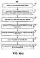
- FIG 4(a) is a process flow chart illustrating an exemplary process 400 for training the system 100 to recognize an object in an image as a finger.
- the process 400 begins by creating a BGM of the IR reflected by the surface 104 or other objects consistently within the ROI 116 (operation 402).
- a large number of input images of a finger 114 positioned in various different orientations then are captured by the camera 108 (operation 404).
- the BGM then is subtracted from each of the input images (operation 406).
- the portion of each image representing the finger 114 then is extracted from the image and converted into a standard n ⁇ n image size (operation 408).
- the portion of each image representing the finger 114 may be extracted using a blob analysis algorithm, such as the Grassfire algorithm, or the portion of each image representing the finger 114 may be extracted manually based on the visual appearance of the image.
- the extracted portion of the image representing the finger may include a large number of pixels.
- the resolution of the extracted portion of the image representing the finger may be reduced.
- the portion of the image representing the finger in the original image may be 64 pixels by 64 pixels. After the 64 ⁇ 64 portion of the image representing the finger is extracted from the image, the resolution of the extracted finger may be reduced such that the finger is represented by a 16 ⁇ 16 image.
- FIG 5 illustrates an exemplary n ⁇ n image 500 of a finger 502.
- Operation 410 An eigenspace for the set of n ⁇ n training images then is defined (operation 410). Operation 410 is illustrated in greater detail in FIG. 4(b) . First, the covariance matrix C of the set of training images is determined (operation 410(a)).
- the covariance matrix C is an m ⁇ m matrix.
- the eigenvalues and eigenvectors of the covariance matrix then may be determined (operation 410(b)).
- A is the set of eigenvalues of the covariance matrix C
- ⁇ is the set of eigenvectors of the covariance matrix C . This process is described in U.S. Patent No. 5,710,833 .
- An m ⁇ m covariance matrix will have m eigenvalues and m eigenvectors, each eigenvector corresponding to a single eigenvalue.
- a 256 ⁇ 256 covariance matrix for a set of 16 ⁇ 16 training images will have 256 eigenvalues and 256 corresponding eigenvectors.
- each eigenvector will be a column vector of length 256.
- an eigenspace for the set of training images may be defined by selecting a set of eigenvectors of the covariance matrix C and using each of the selected eigenvectors to define one direction (i.e., dimension) in the space (operation 410(c)).
- the eigenvectors corresponding to the largest eigenvalues of the covariance matrix C indicate the directions in which the set of training images exhibit the greatest variation. Therefore, a large portion of the data contained within the set of training images may be characterized by selecting a set of eigenvectors corresponding to several of the largest eigenvectors of the covariance matrix C .
- the eigenvectors corresponding to the three largest eigenvalues of the covariance matrix C are selected to define a three-dimensional eigenspace.
- each training image from the set of training images is projected into the eigenspace (operation 410(d)).
- the eigenspace may be defined by an m ⁇ q matrix where q is the number of eigenvectors selected to define the eigenspace and each of the q columns of the matrix represents one of the eigenvectors selected to define the eigenspace.
- the vector V (m) then may be multiplied by the m ⁇ q matrix defining the eigenspace resulting in a 1 ⁇ q matrix, or row vector, wherein each element of the row vector identifies a corresponding coordinate in the eigenspace.
- a 16 ⁇ 16 image I (16 ⁇ 16) may be represented by a 256 ⁇ 1 column vector V (256 ⁇ 1) .
- the transpose of the image vector V 256 ⁇ 1 may be multiplied by the 256 ⁇ 3 matrix defining the eigenspace to obtain a 1 ⁇ 3 row vector defining the three coordinates of the projected image in the three-dimensional eigenspace.
- the projection of an image into an eigenspace may effectively reduce the dimensionality of the image.
- the projection of an image in an eigenspace is a single point with as many coordinates as the dimensions of the eigenspace.
- the projection of an image in a three-dimensional eigenspace is a three-dimensional point (i.e., the point is defined by three coordinates).
- the image is transformed from being defined by n 2 pixels to being defined by a single point identified by three coordinates.
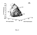
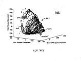
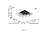
- FIG 6 illustrates an example of a three-dimensional eigenspace 600 for a set of training images of one or more fingers positioned at various orientations.
- the projection of each image of the set of training images is represented by a three-dimensional point in the eigenspace 600. Therefore, as illustrated in FIG 6 , projecting the set of training images into the eigenspace 600 may create a cloud of training points 602 in the eigenspace 600.
- the cloud of training points 602 may exhibit a recognizable geometrical shape. For example, the cloud of training points 602 in FIG. 6 appears to exhibit a hyperboloid-like or cone-like shape.
- the shape of the cloud of training points 602 may be a function of the special features of a finger.
- the finger 114 When a finger 114 is perpendicular to the surface 104, the finger 114 may appear as a substantially circular object in an image captured by the camera 108. Even if the user rotates his/her hand, the finger 114 may continue to appear as a substantially circular object in an image captured by the camera 108 so long as the finger 114 remains perpendicular to the surface 104. In other words, if the finger 114 remains perpendicular to the surface 104, the shape of the finger 114 in a series of images captured by the camera 108 may exhibit only slight variations even if the hand is rotated. This process of exhibiting only slight variations may hold regardless of where, with respect to the camera 108, the finger 114 is pointing on the surface 104.
- the finger 114 may appear as a bright spot with a tail in an image captured by the camera 108.
- the tail may be IR reflected by the body of the finger 114. Consequently, if the hand is rotated, the angle of the tail rotates.
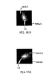
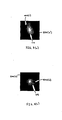
- FIGS. 7(a) and 7(b) are illustrative.
- FIG 7(a) is an n ⁇ n image 700(a) of a finger 114 with a tail 702(a).
- the tail 702(a) is directed toward the upper left corner of the image 700(a).
- FIG 7(b) is an n ⁇ n image 700(b) of the same finger 114 with a tail 702(b).
- the tail 702(b) is directed toward the upper right corner of the image 700(b).
- the different orientation of the tails 702(a), 702(b) may be explained by the fact that the finger 114 is oriented differently with respect to the camera 108 in the two images 700(a), 700(b).
- the finger 114 in image 700(a) and the finger 114 in image 700(b) form the same, non-perpendicular angle with the surface 104.
- the finger 114 in image 700(b) has been rotated from the position of the finger 114 in image 700(a) such that the finger 114 in image 700(a) and the finger 114 in image 700(b) form different angles with a plane (not shown) normal to the surface 104.
- the two images 700(a), 700(b) are different, they will be represented by different points in the cloud of training points 602 in the eigenspace 600.
- the process of projecting images into an eigenspace 600 is a linear process, the projection of a set of images capturing a finger 114 with a tail of substantially the same length but with different angles of rotation may result in a set of points aligned in a substantially circular pattern (not shown) in the eigenspace 600. Therefore, while the two images 700(a), 700(b) will be represented by different points in the cloud of training points 602 in the eigenspace 600, they may be aligned along a substantially circular pattern within the eigenspace 600.
- the length of the tail of a finger in an image may also impact the location of the projection of the image in the eigenspace 600.
- projections of images of fingers with substantially the same tail length but different angles of rotation may be aligned in a substantially circular pattern in the eigenspace 600.
- the projection of a set of images of a finger 114 with the same short tail but different angles of rotation may be aligned in a substantially circular pattern with a smaller relative radius than the projection of a set of images of a finger 114 with the same long tail but different angles of rotation.
- FIGS. 6 , 8(a) , 8(b) , 9(a) , and 9(b) are illustrative.
- the training points that form a vertex 604 of the cloud of training points 602 in FIG 6 may be associated with training images in which the finger 114 appears as a substantially circular shape with little or no tail.
- the training points that form a base 606 of the cloud of training points 602 in FIG 6 may be associated with training images in which the finger 114 is trailed by a long tail.
- FIG. 8(a) illustrates a training image 800(a) of a finger 114 with a relatively long tail 802(a) caused by a relatively small angle between the finger 114 and the surface 104.
- FIG 8(b) illustrates a training image 800(b) of a finger 114 with a relatively shorter tail 802(b) caused by a relatively large angle between the finger 114 and the surface 104.
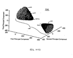
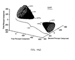
- FIGS. 9(a) and 9(b) illustrate the projections 800(a)', 800(b)' of the two images 800(a), 800(b) in the three-dimensional eigenspace 600.
- the image 800(a) of the finger 114 with the longer tail 802(a) is projected onto a point 800(a)' near the base of the cloud of training points 602 because it has a relatively long tail 802(a).
- the image 800(b) of the finger 114 with the shorter tail 802(b) is projected onto a point 800(b)' near the vertex 604 of the cloud of training points 602 because it has a relatively small tail 802(b).
- FIG. 9(b) illustrates the projections 800(a)', 800(b)' of the two images 800(a), 800(b) in the three-dimensional eigenspace 600 in isolation from the cloud of training points 602.
- the projection 800(a)' is aligned in a substantially circular pattern 902 with projections of images of fingers exhibiting the same relatively long tail but different angles of rotation.
- the projection 800(b)' is aligned in a substantially circular pattern 904 with projections of images of fingers exhibiting the same relatively short tail but different angles of rotation.
- the cloud of training points 602 may exhibit a recognizable geometrical shape and therefore the cloud of training points 602 may be amendable to being modeled by a geometric model capable of being expressed analytically by a polynomial.
- a technique known as the Transfer-to-Centre (TTC) technique may be applied to each of the training points (operation 412).
- TTC technique is described in, for example, Shamaie A. et. al., "International Journal of Scientia Iranica," 6(1), (1999 ).
- the TTC technique transfers the data set to the center of the eigenspace. In other words, the centroid of the data set is moved to the origin of the eigenspace.
- Equation 4 ( a, b, c, d, e, f, g, h, i ).
- the error function may be minimized using a quasi-Newtonian method.
- linear optimization methods like the Quasi-Newtonian method, may stick into local minima because the error function is quadratic.
- applying the TTC technique to the set of training points before minimizing the error function reduces the risk that the quasi-Newtonian minimization method will get stuck in local minima. Therefore, the error function may converge more quickly if the TTC technique is applied to the set of training points before using the quasi-Newtonian method to minimize the error function.
- Minimizing the error function yields values for the set of unknown parameters ⁇ .
- the values determined for ⁇ by minimizing the error function are plugged into Equation 4 to define a model of the cloud of training points 602.
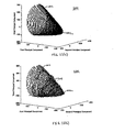
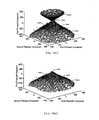
- FIG. 10(a) illustrates the cloud of training points (dark points) 602 overlaying an exemplary model (empty circles) of the cloud of training points 602.
- FIG. 10(b) is a color version of FIG 10(a) .
- the model 1000 may be defined by substituting into Equation 4 the values for the set of parameters ⁇ determined by minimizing the error function.
- the model has a first surface 1002 and a second surface 1004 both of which appear as hyperboloid-like shapes with vertices 1002a and 1004a, respectively, facing each other, and with both surfaces lying on a common axis (not shown).
- only the first surface 1002 is used to model the cloud of training points 602.
- the cloud of training points 602 does not entirely cover first surface 1002 and does not cover second surface 1004 at all.
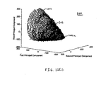
- FIG 11(a) is an illustration of the first surface 1002 of the model 1000 for modeling the cloud of training points 602 in the eigenspace 600. Second surface 1004 is not included in FIGS. 11(a)-(c) .
- FIG 11(b) illustrates the cloud of training points (dark points) 602 overlaying the first surface 1002 of the model (empty circles) 1000.
- FIG 11(c) is a color version of FIG 11(b) .
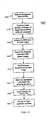
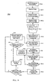
- FIG. 12 is a process flowchart illustrating an exemplary process 1200 for recognizing an object in an image as a finger using a system trained with process 400.
- the process 1200 begins by creating a BGM of the IR consistently reflected by the surface 104 or other objects within the ROI 116 (operation 1202). An input image of the surface 104 and its vicinity then is captured by the camera 108 (operation 1204), and the BGM is subtracted from the input image (operation 1206).
- a blob analysis algorithm like Grassfire, is used to extract objects from the input image (operation 1208).
- each of the objects extracted from the input image is processed to identify and discard objects that are either too small or too large to be a finger (operation 1210).
- the remaining objects are sorted into a list in ascending order of overall area (operation 1212).
- the first object in the list then is converted into an n ⁇ n image and the resized n ⁇ n image is projected into the eigenspace 600 for the set of training data to obtain an image point (operation 1214).
- the TTC technique is applied to the image point to mimic the application of the TTC technique to the points in the cloud of training points 602 during the training stage 400 (operation 1216).
- the same TTC transfer values used in operation 412 may be used in operation 1216.
- the coordinates of the image point are used to evaluate the quadratic polynomial defining the model 1000 of the cloud of training points 602 (operation 1218). If the image point lies on the model 1000, applying the coordinates of the image point to the polynomial will yield a value of zero. In contrast, if the image point does not lie on the model 1000, a non-zero, real number is obtained by applying the coordinates of the image point to the polynomial. The value obtained by applying the coordinates of the image point to the polynomial represents the distance between the image point and the model 1000.
- An image corresponding to an image point that is located close to the model 1000 in the eigenspace 600 may exhibit similar characteristics as the images comprising the set of training images. Accordingly, it may be the case that the closer an image point is located to the model 1000, the more likely it is that the image corresponding to the image point is a finger. Therefore, an image corresponding to an image point that is found to lie on the model 1000 or an image point that falls within a maximum threshold distance of the model 1000 may be determined to be a finger.
- the value obtained by applying the coordinates of the image point to the quadratic polynomial is evaluated to determine whether it is less than a defined threshold distance (operation 1220). If the value obtained by applying the coordinates of the image point to the quadratic polynomial is less than the threshold distance, the object corresponding to the image point is deemed to be a finger (operation 1222). If the value obtained by applying the coordinates of the image point to the quadratic polynomial is greater than the maximum threshold distance, the image corresponding to the image point is discarded and the next object in the list is processed by proceeding to operation 1214 (operation 1224).
- Reducing the dimensionality of an object captured in an image by projecting the object into an eigenspace allows the object to be compared to a model of images of training objects without having to compare each pixel of the captured object with each pixel of the model. As a result, processing power and resources are spared and/or the speed of the comparison is increased.
- FIGS. 13-19 additional implementations of the training and recognition stages are described.
- FIG. 13 is a process flowchart illustrating an example of a process 1300 for training a finger recognition and tracking system 100 to recognize an object as a finger.
- Process 1300 includes the operation of applying a histogram equalization technique to each training image.
- the process 1300 begins by creating a BGM of the IR consistently reflected by the surface 104 or other objects within the ROI 116 (operation 1302).
- a large number of input images of one or more fingers positioned in various different orientations are captured by the camera 108 (operation 1304), and the BGM is subtracted from each of the input images (operation 1306).
- the portion of each image representing the finger is extracted from the image and converted into a standard n ⁇ n image size (operation 1308).
- a histogram equalization technique is applied to each n ⁇ n image (operation 1310).
- the histogram equalization technique is applied to the n ⁇ n images to account for variations in lighting conditions.
- the application of the histogram equalization technique to an n ⁇ n image involves generating a histogram of the intensities of the pixels in the n ⁇ n image, normalizing the histogram of the n ⁇ n image, and reassigning the values of the pixels in the n ⁇ n image based on the normalized image histogram. Consequently, individual pixels retain their brightness order (e.g., they remain brighter or darker than other pixels.
- An eigenspace corresponding to the set of n ⁇ n training images of the finger is created and each training image is projected into the eigenspace (operation 1312).
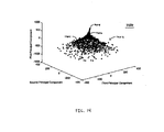
- the projected training images form a cloud of training points 1402 in the eigenspace 1400.
- the TTC technique is applied to the cloud of training points 1402 in order to transfer the centroid of the cloud of training points 1402 to the origin of the eigenspace 1400 (operation 1314).
- the shape of the cloud of training points 1402 in FIG. 14 appears different than the shape of the cloud of training points 602 in FIG. 6 .
- the cloud of training points 1402 in FIG. 14 has a tail 1406 at a vertex 1408 of a cone-like shape 1404.
- the difference in shape between the two clouds of training points 1402, 602 may be attributed to having applied the histogram equalization technique to the set of training images (operation 1310) because the histogram equalization technique reduces variations in the set of training images due to variations in lighting conditions. Consequently, when the training images are projected into the eigenspace 1400, a more uniform shape is obtained.
- the shape of the cloud of training points 602 in FIG. 6 reflects variation in lighting conditions as well as variation in finger shape and orientation within the set of training images.
- the shape of the cloud of training points 1402 in FIG. 14 primarily reflects variation in finger shape and orientation within the set of training images.
- Process 1300 includes fitting one or more models to the transferred cloud of training points 1402 (operation 1316).
- the subset of training points forming the cone-like shape 1404 and the subset of training points forming the tail 1406 are considered separately.
- FIG. 15 illustrates the subset of training points forming the cone-like shape 1404 without the tail 1406.
- FIG. 16 illustrates the subset of training points forming the tail 1406 without the cone-like shape 1404.
- a model may be created of the subset of training points forming the cone-like shape 1404 and a second model may be created of the subset of training points forming the tail 1406.
- Equation 4 provides the general formula for a three-dimensional quadratic surface. Therefore, a model of the set of training points forming the cone-like shape 1404 may be determined by first determining the unknown parameters ⁇ of Equation 4 that minimize the error function of Equation 7 with respect to the set of points in the subset of training points forming the cone-like shape 1404. The values determined for ⁇ by minimizing the error function are plugged into Equation 4 to define a model of the cloud of training points 1402.
- a vertical cone may be used to model the subset of training images forming the cone-like shape 1404.
- the cone-like cloud of training points 1404 exhibits the greatest amount of variation along the vertical axis 1500 representing the first principal component of the eigenspace 1400.
- the height dimension of the cone-like cloud 1404 is parallel to the first principal component of the eigenspace 1400.
- the observation that the cone-like cloud of training points 1404 exhibits the greatest amount of variation along the first principal component of the eigenspace 1400 is consistent with the fact that the eigenvector of the covariance matrix corresponding to the first principal component represents the direction in which the set of training images exhibits the greatest variation.
- Equation 8 In order to fit a vertical cone to the subset of training images forming the cone-like shape 1404, the values of the unknown parameters ⁇ that minimize Equation 8 with respect to the set of points in the subset of training points that forms the cone-like shape 1404 are determined.
- a quasi-Newtonian method may be used to minimize the error function of Equation 9. Minimizing the error function of Equation 9 yields values for the set of unknown parameters ⁇ . These values are plugged into Equation 8 to define a vertical cone model of the subset of training points forming the cone-like shape 1404.
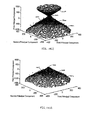
- FIG. 17(a) illustrates the cloud of training points of the cone-like shape (dark diamonds) 1404 overlaying an exemplary vertical cone model (empty circles) 1700 of the cloud of training points of the cone-like shape 1404.
- FIG. 17(c) is a color version of FIG. 17(a) .
- the vertical cone model 1700 has both a bottom surface 1702 and a top surface 1704.
- Each surface 1702 and 1704 forms a conical shape with the two conical shapes meeting at a common vertex 1706.
- the two conical shapes lie on a common axis (not shown).
- the cloud of training points forming the cone-like shape 1404 do not completely cover surface 1702 and do not cover surface 1704 at all.
- FIG. 17(b) illustrates the cloud of training points of the cone-like shape (dark diamonds) 1404 overlaying the lower surface 1702 of the exemplary vertical cone model (empty circles) 1700 of the cloud of training points of the cone-like shape 1404.
- FIG. 17(d) is a color version of FIG. 17(b) .
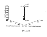
- FIG. 18(a) illustrates the cloud of training points of the tail (dark points) 1406 overlaying an exemplary vertical line model (dark line) 1800 of the cloud of training points forming the tail 1406.
- the cloud of training points forming the tail 1406 are clustered densely around a bottom portion 1810 of the line 1800 and gradually adopt a substantially linear shape nearer a top portion 1820 of the line 1800.
- FIG 18(b) is a color version of FIG 18(a) .
- the line 1800 may not be vertical. Instead, the line 1800 may be oriented so as to best match the set of training points forming the tail 1406.
- FIG 19 is a process flowchart illustrating an example of a process 1900 for recognizing a finger in an image.
- Process 1900 uses a system trained with process 1300.
- the process 1900 begins by creating a BGM of the IR consistently reflected by the surface 104 or other objects within the ROI 116 (operation 1902).
- An input image of the surface 104 and its vicinity is captured by the camera 108 (operation 1904), and the BGM is subtracted from the input image (operation 1906).
- a blob analysis algorithm like Grassfire, is used to extract objects from the input image (operation 1908).
- each of the objects extracted from the input image is processed to identify and discard objects that are either too small or too large to be a finger (operation 1910).
- the remaining objects are sorted into a list in ascending order of overall area (operation 1912).
- the first object in the list then is converted into an n ⁇ n image (operation 1914) and the same histogram equalization technique applied in process 1300 is applied to the resized image (operation 1916).
- the image is projected into the eigenspace for the set of training images and the TTC technique is applied to the image point to mimic the application of the TTC technique to the points in the cloud of training points 1402 during the training stage 1300 (operation 1918).
- Equation 8 defining the vertical cone model 1700 of the cone-like cloud of training points 1404 (operation 1922). If the projected point lies on the surface of the vertical cone model 1700, applying the coordinates of the projected point to Equation 8 yields a value of zero. In contrast, if the image point does not lie on the surface of the vertical cone model 1700, a non-zero, real number is obtained by applying the coordinates of the image point to Equation 8. The value obtained by applying the coordinates of the image point to Equation 8 represents the distance between the image point and the vertical cone model 1700.
- An image corresponding to an image point that is located close to the lower surface 1702 of the vertical cone model 1700 in the eigenspace 1400 may exhibit similar characteristics as some of the images comprising the set of training images. Accordingly, it may be the case that the closer an image is located to the lower surface 1702 of the vertical cone model 1700, the more likely it is that the image corresponding to the image point is a finger.
- An image corresponding to an image point that is found to lie on the lower surface 1702 of the vertical cone model 1700 or an image point that falls within a maximum threshold distance of the lower surface 1702 of the vertical cone model 1700 may be determined to be a finger.
- the value obtained by applying the coordinates of the image point to Equation 8 is evaluated to determine whether it is less than a defined threshold distance (operation 1924). If the value obtained by applying the coordinates of the image point to Equation 8 is less than the threshold distance ("Y" branch out of operation 1924), the image corresponding to the image point is deemed to be a finger (operation 1926). If the value obtained by applying the coordinates of the image point to Equation 8 is greater than the threshold distance ("N" branch out of operation 1924), the image corresponding to the image point is discarded and the next object in the list is processed by proceeding to operation 1914 (operation 1928).
- the "Y" branch is followed out of operation 1920.
- the coordinates of the image point are used to evaluate the equation defining the vertical line model 1800 (operation 1930). If the image point lies on the line 1800, applying the coordinates of the image point to the equation defining the line will yield a value of zero. In contrast, if the image point does not lie on the line 1800, a non-zero, real number will be obtained by applying the coordinates of the image point to the equation defining the line 1800. The value obtained by applying the coordinates of the image point to the equation defining the line 1800 represents the distance between the image point and the line 1800.
- An image corresponding to an image point that is located close to the vertical line model 1800 in the eigenspace 1400 may exhibit similar characteristics as some of the images comprising the set of training images. Accordingly, it may be the case that the closer an image is located to the vertical line model 1800, the more likely it is that the image corresponding to the image point is a finger.
- An image corresponding to an image point that is found to lie on the vertical line model 1800 or an image point that falls within a maximum threshold distance of the vertical line model 1800 may be determined to be a finger.
- the value obtained by applying the coordinates of the image point to the equation defining the line is evaluated to determine whether it is less than the threshold distance (operation 1932). If the value obtained by applying the coordinates of the image point to the equation defining the line is less than the threshold distance ("Y" branch out of operation 1932), the image corresponding to the image point is deemed to be a finger (operation 1926). If the value obtained by applying the coordinates of the image point to the equation defining the line is greater than the threshold distance ("N" branch out of operation 1932), the image corresponding to the image point is discarded and the next object in the list may be processed by proceeding to operation 1914 (operation 1928).
- one technique for adjusting the threshold distance involves applying the coordinates of the training points to the model of the training points.
- a threshold distance that includes 90% of the training points is considered a reasonable choice for the threshold distance in one implementation.
- other threshold distances or percentages may be selected.
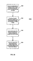
- FIG. 20 is a process flowchart illustrating an example of a process 2000 for recognizing an object in an image.
- the process begins by determining the coordinates for an image point characterizing an object in a multi-dimensional space (operation 2002).
- operation 2002 an image of a particular object is captured by a camera and received as input by a computer or software application.
- the image point characterizes the particular object captured in the image.
- An equation describing a geometric model in the multi-dimensional space that is characteristic of training images is provided (operation 2004).
- the coordinates for the image point are applied to the equation describing the geometric model to determine a distance between the image point and the geometric model (operation 2006).
- determining the coordinates for the image point involves projecting the image into a different multi-dimensional space.
- the multi-dimensional space may be, for example, an eigenspace.
- the geometric model that is characteristic of training images is also in the multi-dimensional space.
- a compact disk (CD), a processing device, or other computer readable medium may contain a program, instructions, or code segments for implementing any of the methods disclosed.
- a tool may be provided for implementing any of the methods disclosed.
- the tool may include, for example, a computer-readable medium, a processing device, a camera, a projector, or a combination of these and possibly other components.
- a processing device may include, for example, a processor, a computer, a programmable logic device, or an integrated circuit.
- Implementations and features may be implemented, at least in part, in a variety of devices. Examples include a computer as described above, including a portable computer or other processing device. Examples also include a portable telephone; a personal digital assistant; a messaging device such as, for example, a pager or a portable e-mail device (such as, for example, a Blackberry®); a portable music player such as, for example, an iPod®; or another electronic portable messaging, entertainment, organization, or gaming device.
- a computer as described above, including a portable computer or other processing device. Examples also include a portable telephone; a personal digital assistant; a messaging device such as, for example, a pager or a portable e-mail device (such as, for example, a Blackberry®); a portable music player such as, for example, an iPod®; or another electronic portable messaging, entertainment, organization, or gaming device.
- systems and methods disclosed generally have been described in the context of recognizing an object in an image as a finger, the ability to recognize other objects in an image are contemplated.
- the systems and methods described may be used to recognize any object that may be modeled by a geometric model in a space, for example, an eigenspace.
- the systems and methods described may be used to recognize an object in an image as a pen or a can.
- elements of different implementations may be combined, supplemented, modified, or removed to produce other implementations.
Claims (14)
- Procédé implémenté par ordinateur comprenant :la fourniture d'une équation décrivant un modèle dans un espace propre multidimensionnel (2004), le modèle étant caractéristique d'un jeu d'images d'apprentissage d'un ou plusieurs doigts, dans lequel l'espace propre multidimensionnel pour le jeu d'images d'apprentissage est créé par l'application d'une analyse de composantes principales ;la détermination de coordonnées pour un point-image dans l'espace propre multidimensionnel (2002), le point-image caractérisant un objet particulier ;l'application des coordonnées à l'équation pour déterminer une distance entre le point-image et le modèle (2006) ; etla détermination selon laquelle l'objet particulier correspond aux un ou plusieurs doigts ou non d'après la distance déterminée (2008), caractérisé en ce quel'équation décrit un hyperboloïde ou une combinaison d'un cône et d'une ligne.
- Procédé selon la revendication 1, comprenant en outre: la réception de l'image de l'objet particulier, l'image ayant un nombre d'éléments de données, et l'espace propre multidimensionnel ayant une dimensionnalité qui est inférieure au nombre d'éléments de données ; et dans lequel la détermination des coordonnées comprend la projection de l'image dans l'espace propre multidimensionnel pour produire les coordonnées pour le point-image dans l'espace multidimensionnel.
- Procédé selon la revendication 2, dans lequel le modèle est un modèle d'un jeu de points d'apprentissage dans l'espace propre multidimensionnel, chacun des points d'apprentissage dans la jeu correspondant à une ou plusieurs images dans le jeu d'imageas d'apprentissage.
- Procédé selon la revendication 2, dans lequel l'image de l'objet particulier est normalisée avant d'être reçue.
- Procédé selon la revendication 4, dans lequel la normalisation de l'image de l'objet particulier rend compte de variations de luminosité.
- Procédé selon la revendication 4, dans lequel la normalisation de l'image de l'objet comprend l'application d'une technique d'égalisation d'histogramme à l'image de l'objet particulier.
- Procédé implémenté par ordinateur selon la revendication 1, dans lequel :la fourniture d'une équation décrivant un modèle dans l'espace propre multidimensionnel comprend la fourniture d'une première équation qui décrit un cône et une seconde équation qui décrit une ligne ; et l'application des coordonnées à l'équation pour déterminer une distance entre le point-image et le modèle comprend l'application des coordonnées à au moins l'une de la première équation et de la seconde équation.
- Procédé selon la revendication 1, dans lequel la fourniture de l'équation comprend la sélection de l'équation parmi une première équation et une seconde équation, la première équation décrivant un premier modèle qui est caractéristique d'un premier jeu d'images d'apprentissage, et la seconde équation décrivant un second modèle qui est caractéristique d'un second Jeu d'images d'apprentissage.
- Système comprenant :une caméra (108) ; etun dispositif de traitement couplé à la caméra (108) et configuré pour :fournir une équation décrivant un modèle dans l'espace propre multidimensionnel, dans lequel l'espace propre multidimensionnel pour le jeu d'images d'apprentissage est créé par l'application d'une analyse de composantes principales ;déterminer des coordonnées pour un point-image dans un espace propre multidimensionnel, le point-image caractérisant un objet particulier ;appliquer les coordonnées à l'équation pour déterminer une distance entre le point-Image et le modèle ; etdéterminer si l'objet particulier correspond aux un ou plusieurs doigts ou non d'après la distance déterminée, caractérisé en ce que :l'équation décrit un hyperboloïde ou une combinaison d'un cône et d'une ligne.
- Système selon la revendication 9, dans lequel la caméra (108) comprend une caméra IR.
- Système selon la revendication 10, comprenant en outre une source IR (102).
- Système selon la revendication 9, comprenant en outre un écran (104) disposé devant la caméra (108).
- Système selon la revendication 12, dans lequel l'écran (104) est au moins translucide de sorte que la lumière réfléchie par un objet (114 ; 118) disposé d'un côté de l'écran (104) en regard de la caméra (108) puisse traverser l'écran (104) et être reçue par la caméra (108).
- Programme informatique contenu sur un support lisible par ordinateur comprenant des instructions adaptées pour amener un dispositif de traitement à implémenter un procédé selon l'une quelconque des revendications 1 à 8.
Priority Applications (2)
| Application Number | Priority Date | Filing Date | Title |
|---|---|---|---|
| EP20151279.5A EP3693889A3 (fr) | 2005-01-07 | 2006-01-06 | Detection et suivi d'objets dans des images |
| EP12156622.8A EP2487624B1 (fr) | 2005-01-07 | 2006-01-06 | Detection et suivi d'objets dans des images |
Applications Claiming Priority (2)
| Application Number | Priority Date | Filing Date | Title |
|---|---|---|---|
| US64173405P | 2005-01-07 | 2005-01-07 | |
| PCT/US2006/000294 WO2006074289A2 (fr) | 2005-01-07 | 2006-01-06 | Detection et suivi d'objets dans des images |
Related Child Applications (3)
| Application Number | Title | Priority Date | Filing Date |
|---|---|---|---|
| EP12156622.8A Division EP2487624B1 (fr) | 2005-01-07 | 2006-01-06 | Detection et suivi d'objets dans des images |
| EP20151279.5A Division EP3693889A3 (fr) | 2005-01-07 | 2006-01-06 | Detection et suivi d'objets dans des images |
| EP12156622.8 Division-Into | 2012-02-23 |
Publications (3)
| Publication Number | Publication Date |
|---|---|
| EP1856470A2 EP1856470A2 (fr) | 2007-11-21 |
| EP1856470A4 EP1856470A4 (fr) | 2010-01-20 |
| EP1856470B1 true EP1856470B1 (fr) | 2013-02-27 |
Family
ID=36648170
Family Applications (3)
| Application Number | Title | Priority Date | Filing Date |
|---|---|---|---|
| EP20151279.5A Pending EP3693889A3 (fr) | 2005-01-07 | 2006-01-06 | Detection et suivi d'objets dans des images |
| EP12156622.8A Active EP2487624B1 (fr) | 2005-01-07 | 2006-01-06 | Detection et suivi d'objets dans des images |
| EP06717487A Active EP1856470B1 (fr) | 2005-01-07 | 2006-01-06 | Detection et suivi d'objets dans des images |
Family Applications Before (2)
| Application Number | Title | Priority Date | Filing Date |
|---|---|---|---|
| EP20151279.5A Pending EP3693889A3 (fr) | 2005-01-07 | 2006-01-06 | Detection et suivi d'objets dans des images |
| EP12156622.8A Active EP2487624B1 (fr) | 2005-01-07 | 2006-01-06 | Detection et suivi d'objets dans des images |
Country Status (7)
| Country | Link |
|---|---|
| US (4) | US7853041B2 (fr) |
| EP (3) | EP3693889A3 (fr) |
| JP (2) | JP5160235B2 (fr) |
| CN (2) | CN101622630B (fr) |
| ES (1) | ES2791718T3 (fr) |
| HU (1) | HUE049974T2 (fr) |
| WO (1) | WO2006074289A2 (fr) |
Families Citing this family (347)
| Publication number | Priority date | Publication date | Assignee | Title |
|---|---|---|---|---|
| US8352400B2 (en) | 1991-12-23 | 2013-01-08 | Hoffberg Steven M | Adaptive pattern recognition based controller apparatus and method and human-factored interface therefore |
| US7966078B2 (en) | 1999-02-01 | 2011-06-21 | Steven Hoffberg | Network media appliance system and method |
| US6990639B2 (en) | 2002-02-07 | 2006-01-24 | Microsoft Corporation | System and process for controlling electronic components in a ubiquitous computing environment using multimodal integration |
| US7665041B2 (en) | 2003-03-25 | 2010-02-16 | Microsoft Corporation | Architecture for controlling a computer using hand gestures |
| US8745541B2 (en) | 2003-03-25 | 2014-06-03 | Microsoft Corporation | Architecture for controlling a computer using hand gestures |
| WO2006074289A2 (fr) | 2005-01-07 | 2006-07-13 | Gesturetek, Inc. | Detection et suivi d'objets dans des images |
| CN101536494B (zh) * | 2005-02-08 | 2017-04-26 | 奥布隆工业有限公司 | 用于基于姿势的控制系统的系统和方法 |
| US7697827B2 (en) | 2005-10-17 | 2010-04-13 | Konicek Jeffrey C | User-friendlier interfaces for a camera |
| US8537111B2 (en) * | 2006-02-08 | 2013-09-17 | Oblong Industries, Inc. | Control system for navigating a principal dimension of a data space |
| US9910497B2 (en) * | 2006-02-08 | 2018-03-06 | Oblong Industries, Inc. | Gestural control of autonomous and semi-autonomous systems |
| US9823747B2 (en) | 2006-02-08 | 2017-11-21 | Oblong Industries, Inc. | Spatial, multi-modal control device for use with spatial operating system |
| US8537112B2 (en) * | 2006-02-08 | 2013-09-17 | Oblong Industries, Inc. | Control system for navigating a principal dimension of a data space |
| US8531396B2 (en) | 2006-02-08 | 2013-09-10 | Oblong Industries, Inc. | Control system for navigating a principal dimension of a data space |
| US9075441B2 (en) * | 2006-02-08 | 2015-07-07 | Oblong Industries, Inc. | Gesture based control using three-dimensional information extracted over an extended depth of field |
| US8370383B2 (en) | 2006-02-08 | 2013-02-05 | Oblong Industries, Inc. | Multi-process interactive systems and methods |
| US7415385B2 (en) * | 2006-11-29 | 2008-08-19 | Mitsubishi Electric Research Laboratories, Inc. | System and method for measuring performances of surveillance systems |
| US8130203B2 (en) | 2007-01-03 | 2012-03-06 | Apple Inc. | Multi-touch input discrimination |
| US7855718B2 (en) * | 2007-01-03 | 2010-12-21 | Apple Inc. | Multi-touch input discrimination |
| US8269727B2 (en) | 2007-01-03 | 2012-09-18 | Apple Inc. | Irregular input identification |
| US8005238B2 (en) | 2007-03-22 | 2011-08-23 | Microsoft Corporation | Robust adaptive beamforming with enhanced noise suppression |
| JP4787782B2 (ja) * | 2007-03-30 | 2011-10-05 | 富士通コンポーネント株式会社 | 機器操作システム、制御装置 |
| JP5005413B2 (ja) * | 2007-04-09 | 2012-08-22 | 株式会社東海理化電機製作所 | 車載機器制御装置 |
| US8577126B2 (en) * | 2007-04-11 | 2013-11-05 | Irobot Corporation | System and method for cooperative remote vehicle behavior |
| EP2150893A4 (fr) | 2007-04-24 | 2012-08-22 | Oblong Ind Inc | Protéines, pools et slaws (fiche d'analyse logistique de poste) dans des environnements de traitement |
| EP2153377A4 (fr) * | 2007-05-04 | 2017-05-31 | Qualcomm Incorporated | Entrée utilisateur basée sur caméra pour dispositifs compacts |
| JP4769983B2 (ja) * | 2007-05-17 | 2011-09-07 | 独立行政法人産業技術総合研究所 | 異常検出装置および異常検出方法 |
| US8005237B2 (en) | 2007-05-17 | 2011-08-23 | Microsoft Corp. | Sensor array beamformer post-processor |
| US8629976B2 (en) | 2007-10-02 | 2014-01-14 | Microsoft Corporation | Methods and systems for hierarchical de-aliasing time-of-flight (TOF) systems |
| WO2009128064A2 (fr) * | 2008-04-14 | 2009-10-22 | Pointgrab Ltd. | Emulation d’un dispositif de pointage basé sur la vision |
| US9684380B2 (en) | 2009-04-02 | 2017-06-20 | Oblong Industries, Inc. | Operating environment with gestural control and multiple client devices, displays, and users |
| US9740922B2 (en) | 2008-04-24 | 2017-08-22 | Oblong Industries, Inc. | Adaptive tracking system for spatial input devices |
| US10642364B2 (en) | 2009-04-02 | 2020-05-05 | Oblong Industries, Inc. | Processing tracking and recognition data in gestural recognition systems |
| US9952673B2 (en) | 2009-04-02 | 2018-04-24 | Oblong Industries, Inc. | Operating environment comprising multiple client devices, multiple displays, multiple users, and gestural control |
| US9495013B2 (en) | 2008-04-24 | 2016-11-15 | Oblong Industries, Inc. | Multi-modal gestural interface |
| US8723795B2 (en) | 2008-04-24 | 2014-05-13 | Oblong Industries, Inc. | Detecting, representing, and interpreting three-space input: gestural continuum subsuming freespace, proximal, and surface-contact modes |
| US9740293B2 (en) | 2009-04-02 | 2017-08-22 | Oblong Industries, Inc. | Operating environment with gestural control and multiple client devices, displays, and users |
| US9753948B2 (en) * | 2008-05-27 | 2017-09-05 | Match.Com, L.L.C. | Face search in personals |
| EP2304527A4 (fr) * | 2008-06-18 | 2013-03-27 | Oblong Ind Inc | Système de commande sur la base de gestes pour des interfaces de véhicule |
| US8385557B2 (en) | 2008-06-19 | 2013-02-26 | Microsoft Corporation | Multichannel acoustic echo reduction |
| US8325909B2 (en) | 2008-06-25 | 2012-12-04 | Microsoft Corporation | Acoustic echo suppression |
| US8203699B2 (en) | 2008-06-30 | 2012-06-19 | Microsoft Corporation | System architecture design for time-of-flight system having reduced differential pixel size, and time-of-flight systems so designed |
| US9030564B2 (en) * | 2008-10-10 | 2015-05-12 | Qualcomm Incorporated | Single camera tracker |
| US9383814B1 (en) | 2008-11-12 | 2016-07-05 | David G. Capper | Plug and play wireless video game |
| US10086262B1 (en) | 2008-11-12 | 2018-10-02 | David G. Capper | Video motion capture for wireless gaming |
| US9586135B1 (en) | 2008-11-12 | 2017-03-07 | David G. Capper | Video motion capture for wireless gaming |
| KR101577953B1 (ko) * | 2008-12-16 | 2015-12-17 | 삼성디스플레이 주식회사 | 접촉 감지 기능이 있는 표시 장치 및 접촉 판단 방법 |
| US8681321B2 (en) | 2009-01-04 | 2014-03-25 | Microsoft International Holdings B.V. | Gated 3D camera |
| US8295546B2 (en) | 2009-01-30 | 2012-10-23 | Microsoft Corporation | Pose tracking pipeline |
| US8565476B2 (en) | 2009-01-30 | 2013-10-22 | Microsoft Corporation | Visual target tracking |
| US20100199231A1 (en) | 2009-01-30 | 2010-08-05 | Microsoft Corporation | Predictive determination |
| US8682028B2 (en) | 2009-01-30 | 2014-03-25 | Microsoft Corporation | Visual target tracking |
| US8565477B2 (en) | 2009-01-30 | 2013-10-22 | Microsoft Corporation | Visual target tracking |
| US9652030B2 (en) * | 2009-01-30 | 2017-05-16 | Microsoft Technology Licensing, Llc | Navigation of a virtual plane using a zone of restriction for canceling noise |
| US8577084B2 (en) | 2009-01-30 | 2013-11-05 | Microsoft Corporation | Visual target tracking |
| US8448094B2 (en) | 2009-01-30 | 2013-05-21 | Microsoft Corporation | Mapping a natural input device to a legacy system |
| US8588465B2 (en) | 2009-01-30 | 2013-11-19 | Microsoft Corporation | Visual target tracking |
| US8487938B2 (en) | 2009-01-30 | 2013-07-16 | Microsoft Corporation | Standard Gestures |
| US7996793B2 (en) | 2009-01-30 | 2011-08-09 | Microsoft Corporation | Gesture recognizer system architecture |
| US8294767B2 (en) | 2009-01-30 | 2012-10-23 | Microsoft Corporation | Body scan |
| US8577085B2 (en) | 2009-01-30 | 2013-11-05 | Microsoft Corporation | Visual target tracking |
| US8267781B2 (en) | 2009-01-30 | 2012-09-18 | Microsoft Corporation | Visual target tracking |
| US8624962B2 (en) * | 2009-02-02 | 2014-01-07 | Ydreams—Informatica, S.A. Ydreams | Systems and methods for simulating three-dimensional virtual interactions from two-dimensional camera images |
| US8517834B2 (en) * | 2009-02-17 | 2013-08-27 | Softkinetic Studios Sa | Computer videogame system with body position detector that requires user to assume various body positions |
| US8773355B2 (en) | 2009-03-16 | 2014-07-08 | Microsoft Corporation | Adaptive cursor sizing |
| US9256282B2 (en) | 2009-03-20 | 2016-02-09 | Microsoft Technology Licensing, Llc | Virtual object manipulation |
| US8988437B2 (en) | 2009-03-20 | 2015-03-24 | Microsoft Technology Licensing, Llc | Chaining animations |
| US9313376B1 (en) | 2009-04-01 | 2016-04-12 | Microsoft Technology Licensing, Llc | Dynamic depth power equalization |
| US9317128B2 (en) | 2009-04-02 | 2016-04-19 | Oblong Industries, Inc. | Remote devices used in a markerless installation of a spatial operating environment incorporating gestural control |
| US10824238B2 (en) | 2009-04-02 | 2020-11-03 | Oblong Industries, Inc. | Operating environment with gestural control and multiple client devices, displays, and users |
| GB0906461D0 (en) * | 2009-04-15 | 2009-05-20 | Siemens Medical Solutions | Partial volume correction via smoothing at viewer |
| US8181123B2 (en) | 2009-05-01 | 2012-05-15 | Microsoft Corporation | Managing virtual port associations to users in a gesture-based computing environment |
| US8649554B2 (en) | 2009-05-01 | 2014-02-11 | Microsoft Corporation | Method to control perspective for a camera-controlled computer |
| US8638985B2 (en) * | 2009-05-01 | 2014-01-28 | Microsoft Corporation | Human body pose estimation |
| US9898675B2 (en) | 2009-05-01 | 2018-02-20 | Microsoft Technology Licensing, Llc | User movement tracking feedback to improve tracking |
| US8660303B2 (en) | 2009-05-01 | 2014-02-25 | Microsoft Corporation | Detection of body and props |
| US8503720B2 (en) | 2009-05-01 | 2013-08-06 | Microsoft Corporation | Human body pose estimation |
| US8253746B2 (en) | 2009-05-01 | 2012-08-28 | Microsoft Corporation | Determine intended motions |
| US8942428B2 (en) | 2009-05-01 | 2015-01-27 | Microsoft Corporation | Isolate extraneous motions |
| US9377857B2 (en) | 2009-05-01 | 2016-06-28 | Microsoft Technology Licensing, Llc | Show body position |
| US9498718B2 (en) | 2009-05-01 | 2016-11-22 | Microsoft Technology Licensing, Llc | Altering a view perspective within a display environment |
| US9015638B2 (en) | 2009-05-01 | 2015-04-21 | Microsoft Technology Licensing, Llc | Binding users to a gesture based system and providing feedback to the users |
| US8340432B2 (en) | 2009-05-01 | 2012-12-25 | Microsoft Corporation | Systems and methods for detecting a tilt angle from a depth image |
| US20100295782A1 (en) | 2009-05-21 | 2010-11-25 | Yehuda Binder | System and method for control based on face ore hand gesture detection |
| US9417700B2 (en) | 2009-05-21 | 2016-08-16 | Edge3 Technologies | Gesture recognition systems and related methods |
| US8693724B2 (en) | 2009-05-29 | 2014-04-08 | Microsoft Corporation | Method and system implementing user-centric gesture control |
| US9383823B2 (en) * | 2009-05-29 | 2016-07-05 | Microsoft Technology Licensing, Llc | Combining gestures beyond skeletal |
| US9400559B2 (en) | 2009-05-29 | 2016-07-26 | Microsoft Technology Licensing, Llc | Gesture shortcuts |
| US8625837B2 (en) | 2009-05-29 | 2014-01-07 | Microsoft Corporation | Protocol and format for communicating an image from a camera to a computing environment |
| US8509479B2 (en) | 2009-05-29 | 2013-08-13 | Microsoft Corporation | Virtual object |
| US8379101B2 (en) | 2009-05-29 | 2013-02-19 | Microsoft Corporation | Environment and/or target segmentation |
| US8418085B2 (en) | 2009-05-29 | 2013-04-09 | Microsoft Corporation | Gesture coach |
| US8856691B2 (en) | 2009-05-29 | 2014-10-07 | Microsoft Corporation | Gesture tool |
| US8744121B2 (en) | 2009-05-29 | 2014-06-03 | Microsoft Corporation | Device for identifying and tracking multiple humans over time |
| US8320619B2 (en) | 2009-05-29 | 2012-11-27 | Microsoft Corporation | Systems and methods for tracking a model |
| US9182814B2 (en) | 2009-05-29 | 2015-11-10 | Microsoft Technology Licensing, Llc | Systems and methods for estimating a non-visible or occluded body part |
| US8542252B2 (en) | 2009-05-29 | 2013-09-24 | Microsoft Corporation | Target digitization, extraction, and tracking |
| US8487871B2 (en) | 2009-06-01 | 2013-07-16 | Microsoft Corporation | Virtual desktop coordinate transformation |
| KR101640077B1 (ko) | 2009-06-05 | 2016-07-15 | 삼성전자주식회사 | 인체 동작 및 얼굴 표정 모델링 및 인식을 위한 비디오 센서 기반의 장치 및 방법 |
| US8860693B2 (en) * | 2009-07-08 | 2014-10-14 | Apple Inc. | Image processing for camera based motion tracking |
| US8390680B2 (en) | 2009-07-09 | 2013-03-05 | Microsoft Corporation | Visual representation expression based on player expression |
| US9159151B2 (en) | 2009-07-13 | 2015-10-13 | Microsoft Technology Licensing, Llc | Bringing a visual representation to life via learned input from the user |
| US8264536B2 (en) | 2009-08-25 | 2012-09-11 | Microsoft Corporation | Depth-sensitive imaging via polarization-state mapping |
| US9141193B2 (en) | 2009-08-31 | 2015-09-22 | Microsoft Technology Licensing, Llc | Techniques for using human gestures to control gesture unaware programs |
| US8330134B2 (en) | 2009-09-14 | 2012-12-11 | Microsoft Corporation | Optical fault monitoring |
| US8508919B2 (en) | 2009-09-14 | 2013-08-13 | Microsoft Corporation | Separation of electrical and optical components |
| US8976986B2 (en) | 2009-09-21 | 2015-03-10 | Microsoft Technology Licensing, Llc | Volume adjustment based on listener position |
| US8760571B2 (en) | 2009-09-21 | 2014-06-24 | Microsoft Corporation | Alignment of lens and image sensor |
| US8428340B2 (en) | 2009-09-21 | 2013-04-23 | Microsoft Corporation | Screen space plane identification |
| US9014546B2 (en) | 2009-09-23 | 2015-04-21 | Rovi Guides, Inc. | Systems and methods for automatically detecting users within detection regions of media devices |
| US8452087B2 (en) | 2009-09-30 | 2013-05-28 | Microsoft Corporation | Image selection techniques |
| US8723118B2 (en) | 2009-10-01 | 2014-05-13 | Microsoft Corporation | Imager for constructing color and depth images |
| US8963829B2 (en) | 2009-10-07 | 2015-02-24 | Microsoft Corporation | Methods and systems for determining and tracking extremities of a target |
| US7961910B2 (en) | 2009-10-07 | 2011-06-14 | Microsoft Corporation | Systems and methods for tracking a model |
| US8564534B2 (en) | 2009-10-07 | 2013-10-22 | Microsoft Corporation | Human tracking system |
| US8867820B2 (en) | 2009-10-07 | 2014-10-21 | Microsoft Corporation | Systems and methods for removing a background of an image |
| GB2474536B (en) | 2009-10-13 | 2011-11-02 | Pointgrab Ltd | Computer vision gesture based control of a device |
| US9933852B2 (en) | 2009-10-14 | 2018-04-03 | Oblong Industries, Inc. | Multi-process interactive systems and methods |
| US9971807B2 (en) | 2009-10-14 | 2018-05-15 | Oblong Industries, Inc. | Multi-process interactive systems and methods |
| US9400548B2 (en) | 2009-10-19 | 2016-07-26 | Microsoft Technology Licensing, Llc | Gesture personalization and profile roaming |
| US8723987B2 (en) * | 2009-10-30 | 2014-05-13 | Honeywell International Inc. | Uncertainty estimation of planar features |
| US8988432B2 (en) | 2009-11-05 | 2015-03-24 | Microsoft Technology Licensing, Llc | Systems and methods for processing an image for target tracking |
| GB0920111D0 (en) | 2009-11-18 | 2009-12-30 | Bae Systems Plc | Image processing |
| US8843857B2 (en) | 2009-11-19 | 2014-09-23 | Microsoft Corporation | Distance scalable no touch computing |
| JP5740844B2 (ja) * | 2009-11-24 | 2015-07-01 | 株式会社リコー | 撮像装置、画像処理方法、及び、コンピュータプログラム |
| US8325136B2 (en) | 2009-12-01 | 2012-12-04 | Raytheon Company | Computer display pointer device for a display |
| US9244533B2 (en) | 2009-12-17 | 2016-01-26 | Microsoft Technology Licensing, Llc | Camera navigation for presentations |
| US20110150271A1 (en) | 2009-12-18 | 2011-06-23 | Microsoft Corporation | Motion detection using depth images |
| US8320621B2 (en) | 2009-12-21 | 2012-11-27 | Microsoft Corporation | Depth projector system with integrated VCSEL array |
| US9019201B2 (en) | 2010-01-08 | 2015-04-28 | Microsoft Technology Licensing, Llc | Evolving universal gesture sets |
| US9268404B2 (en) | 2010-01-08 | 2016-02-23 | Microsoft Technology Licensing, Llc | Application gesture interpretation |
| US8631355B2 (en) | 2010-01-08 | 2014-01-14 | Microsoft Corporation | Assigning gesture dictionaries |
| US8842096B2 (en) * | 2010-01-08 | 2014-09-23 | Crayola Llc | Interactive projection system |
| US8334842B2 (en) | 2010-01-15 | 2012-12-18 | Microsoft Corporation | Recognizing user intent in motion capture system |
| US8933884B2 (en) | 2010-01-15 | 2015-01-13 | Microsoft Corporation | Tracking groups of users in motion capture system |
| US8676581B2 (en) | 2010-01-22 | 2014-03-18 | Microsoft Corporation | Speech recognition analysis via identification information |
| US8265341B2 (en) | 2010-01-25 | 2012-09-11 | Microsoft Corporation | Voice-body identity correlation |
| US8864581B2 (en) | 2010-01-29 | 2014-10-21 | Microsoft Corporation | Visual based identitiy tracking |
| US20110187678A1 (en) * | 2010-01-29 | 2011-08-04 | Tyco Electronics Corporation | Touch system using optical components to image multiple fields of view on an image sensor |
| US8891067B2 (en) | 2010-02-01 | 2014-11-18 | Microsoft Corporation | Multiple synchronized optical sources for time-of-flight range finding systems |
| US8619122B2 (en) | 2010-02-02 | 2013-12-31 | Microsoft Corporation | Depth camera compatibility |
| US8687044B2 (en) | 2010-02-02 | 2014-04-01 | Microsoft Corporation | Depth camera compatibility |
| US8717469B2 (en) | 2010-02-03 | 2014-05-06 | Microsoft Corporation | Fast gating photosurface |
| KR101184460B1 (ko) * | 2010-02-05 | 2012-09-19 | 연세대학교 산학협력단 | 마우스 포인터 제어 장치 및 방법 |
| US8499257B2 (en) | 2010-02-09 | 2013-07-30 | Microsoft Corporation | Handles interactions for human—computer interface |
| US8659658B2 (en) | 2010-02-09 | 2014-02-25 | Microsoft Corporation | Physical interaction zone for gesture-based user interfaces |
| US8633890B2 (en) | 2010-02-16 | 2014-01-21 | Microsoft Corporation | Gesture detection based on joint skipping |
| US8928579B2 (en) | 2010-02-22 | 2015-01-06 | Andrew David Wilson | Interacting with an omni-directionally projected display |
| US8411948B2 (en) | 2010-03-05 | 2013-04-02 | Microsoft Corporation | Up-sampling binary images for segmentation |
| US8655069B2 (en) | 2010-03-05 | 2014-02-18 | Microsoft Corporation | Updating image segmentation following user input |
| US8422769B2 (en) | 2010-03-05 | 2013-04-16 | Microsoft Corporation | Image segmentation using reduced foreground training data |
| US9098905B2 (en) | 2010-03-12 | 2015-08-04 | Google Inc. | System and method for determining position of a device |
| US20110223995A1 (en) | 2010-03-12 | 2011-09-15 | Kevin Geisner | Interacting with a computer based application |
| US8279418B2 (en) | 2010-03-17 | 2012-10-02 | Microsoft Corporation | Raster scanning for depth detection |
| US8213680B2 (en) | 2010-03-19 | 2012-07-03 | Microsoft Corporation | Proxy training data for human body tracking |
| US8514269B2 (en) | 2010-03-26 | 2013-08-20 | Microsoft Corporation | De-aliasing depth images |
| US8523667B2 (en) | 2010-03-29 | 2013-09-03 | Microsoft Corporation | Parental control settings based on body dimensions |
| US8605763B2 (en) | 2010-03-31 | 2013-12-10 | Microsoft Corporation | Temperature measurement and control for laser and light-emitting diodes |
| WO2013189058A1 (fr) | 2012-06-21 | 2013-12-27 | Microsoft Corporation | Construction d'avatar au moyen d'une caméra de profondeur |
| US9646340B2 (en) | 2010-04-01 | 2017-05-09 | Microsoft Technology Licensing, Llc | Avatar-based virtual dressing room |
| US9098873B2 (en) | 2010-04-01 | 2015-08-04 | Microsoft Technology Licensing, Llc | Motion-based interactive shopping environment |
| US8818027B2 (en) | 2010-04-01 | 2014-08-26 | Qualcomm Incorporated | Computing device interface |
| US9491055B1 (en) * | 2010-04-21 | 2016-11-08 | Sprint Communications Company L.P. | Determining user communities in communication networks |
| US8351651B2 (en) | 2010-04-26 | 2013-01-08 | Microsoft Corporation | Hand-location post-process refinement in a tracking system |
| US8379919B2 (en) | 2010-04-29 | 2013-02-19 | Microsoft Corporation | Multiple centroid condensation of probability distribution clouds |
| US8284847B2 (en) | 2010-05-03 | 2012-10-09 | Microsoft Corporation | Detecting motion for a multifunction sensor device |
| US8498481B2 (en) | 2010-05-07 | 2013-07-30 | Microsoft Corporation | Image segmentation using star-convexity constraints |
| US8885890B2 (en) | 2010-05-07 | 2014-11-11 | Microsoft Corporation | Depth map confidence filtering |
| US8457353B2 (en) | 2010-05-18 | 2013-06-04 | Microsoft Corporation | Gestures and gesture modifiers for manipulating a user-interface |
| US8396252B2 (en) | 2010-05-20 | 2013-03-12 | Edge 3 Technologies | Systems and related methods for three dimensional gesture recognition in vehicles |
| US8803888B2 (en) | 2010-06-02 | 2014-08-12 | Microsoft Corporation | Recognition system for sharing information |
| US9008355B2 (en) | 2010-06-04 | 2015-04-14 | Microsoft Technology Licensing, Llc | Automatic depth camera aiming |
| US8751215B2 (en) | 2010-06-04 | 2014-06-10 | Microsoft Corporation | Machine based sign language interpreter |
| US9557574B2 (en) | 2010-06-08 | 2017-01-31 | Microsoft Technology Licensing, Llc | Depth illumination and detection optics |
| US8330822B2 (en) | 2010-06-09 | 2012-12-11 | Microsoft Corporation | Thermally-tuned depth camera light source |
| US8749557B2 (en) | 2010-06-11 | 2014-06-10 | Microsoft Corporation | Interacting with user interface via avatar |
| US8675981B2 (en) | 2010-06-11 | 2014-03-18 | Microsoft Corporation | Multi-modal gender recognition including depth data |
| US9384329B2 (en) | 2010-06-11 | 2016-07-05 | Microsoft Technology Licensing, Llc | Caloric burn determination from body movement |
| US8982151B2 (en) | 2010-06-14 | 2015-03-17 | Microsoft Technology Licensing, Llc | Independently processing planes of display data |
| US8670029B2 (en) | 2010-06-16 | 2014-03-11 | Microsoft Corporation | Depth camera illuminator with superluminescent light-emitting diode |
| US8558873B2 (en) | 2010-06-16 | 2013-10-15 | Microsoft Corporation | Use of wavefront coding to create a depth image |
| US8296151B2 (en) | 2010-06-18 | 2012-10-23 | Microsoft Corporation | Compound gesture-speech commands |
| US8381108B2 (en) | 2010-06-21 | 2013-02-19 | Microsoft Corporation | Natural user input for driving interactive stories |
| WO2011161673A2 (fr) * | 2010-06-21 | 2011-12-29 | N-Trig Ltd. | Système et procédé de résolution digitale dans des écrans tactiles |
| US8416187B2 (en) | 2010-06-22 | 2013-04-09 | Microsoft Corporation | Item navigation using motion-capture data |
| TW201201079A (en) * | 2010-06-23 | 2012-01-01 | Pixart Imaging Inc | Optical touch monitor |
| US8976929B2 (en) * | 2010-07-16 | 2015-03-10 | Duke University | Automatic generation of patient-specific radiation therapy planning parameters |
| US8660365B2 (en) | 2010-07-29 | 2014-02-25 | Honeywell International Inc. | Systems and methods for processing extracted plane features |
| US20130135199A1 (en) * | 2010-08-10 | 2013-05-30 | Pointgrab Ltd | System and method for user interaction with projected content |
| US9075434B2 (en) | 2010-08-20 | 2015-07-07 | Microsoft Technology Licensing, Llc | Translating user motion into multiple object responses |
| US8613666B2 (en) | 2010-08-31 | 2013-12-24 | Microsoft Corporation | User selection and navigation based on looped motions |
| US8655093B2 (en) | 2010-09-02 | 2014-02-18 | Edge 3 Technologies, Inc. | Method and apparatus for performing segmentation of an image |
| US8666144B2 (en) | 2010-09-02 | 2014-03-04 | Edge 3 Technologies, Inc. | Method and apparatus for determining disparity of texture |
| WO2012030872A1 (fr) | 2010-09-02 | 2012-03-08 | Edge3 Technologies Inc. | Procédé et dispositif d'apprentissage par l'erreur |
| US8582866B2 (en) | 2011-02-10 | 2013-11-12 | Edge 3 Technologies, Inc. | Method and apparatus for disparity computation in stereo images |
| US20120058824A1 (en) | 2010-09-07 | 2012-03-08 | Microsoft Corporation | Scalable real-time motion recognition |
| US8437506B2 (en) | 2010-09-07 | 2013-05-07 | Microsoft Corporation | System for fast, probabilistic skeletal tracking |
| US8988508B2 (en) | 2010-09-24 | 2015-03-24 | Microsoft Technology Licensing, Llc. | Wide angle field of view active illumination imaging system |
| US8681255B2 (en) | 2010-09-28 | 2014-03-25 | Microsoft Corporation | Integrated low power depth camera and projection device |
| US8548270B2 (en) | 2010-10-04 | 2013-10-01 | Microsoft Corporation | Time-of-flight depth imaging |
| US9484065B2 (en) | 2010-10-15 | 2016-11-01 | Microsoft Technology Licensing, Llc | Intelligent determination of replays based on event identification |
| US8592739B2 (en) | 2010-11-02 | 2013-11-26 | Microsoft Corporation | Detection of configuration changes of an optical element in an illumination system |
| US8866889B2 (en) | 2010-11-03 | 2014-10-21 | Microsoft Corporation | In-home depth camera calibration |
| US8667519B2 (en) | 2010-11-12 | 2014-03-04 | Microsoft Corporation | Automatic passive and anonymous feedback system |
| CN102012740B (zh) * | 2010-11-15 | 2015-10-21 | 中国科学院深圳先进技术研究院 | 人机交互方法及系统 |
| US10726861B2 (en) | 2010-11-15 | 2020-07-28 | Microsoft Technology Licensing, Llc | Semi-private communication in open environments |
| US9349040B2 (en) | 2010-11-19 | 2016-05-24 | Microsoft Technology Licensing, Llc | Bi-modal depth-image analysis |
| US10234545B2 (en) | 2010-12-01 | 2019-03-19 | Microsoft Technology Licensing, Llc | Light source module |
| US8553934B2 (en) | 2010-12-08 | 2013-10-08 | Microsoft Corporation | Orienting the position of a sensor |
| US8618405B2 (en) | 2010-12-09 | 2013-12-31 | Microsoft Corp. | Free-space gesture musical instrument digital interface (MIDI) controller |
| US8408706B2 (en) | 2010-12-13 | 2013-04-02 | Microsoft Corporation | 3D gaze tracker |
| US9171264B2 (en) | 2010-12-15 | 2015-10-27 | Microsoft Technology Licensing, Llc | Parallel processing machine learning decision tree training |
| US8920241B2 (en) | 2010-12-15 | 2014-12-30 | Microsoft Corporation | Gesture controlled persistent handles for interface guides |
| US8884968B2 (en) | 2010-12-15 | 2014-11-11 | Microsoft Corporation | Modeling an object from image data |
| US8448056B2 (en) | 2010-12-17 | 2013-05-21 | Microsoft Corporation | Validation analysis of human target |
| US8803952B2 (en) | 2010-12-20 | 2014-08-12 | Microsoft Corporation | Plural detector time-of-flight depth mapping |
| US9821224B2 (en) | 2010-12-21 | 2017-11-21 | Microsoft Technology Licensing, Llc | Driving simulator control with virtual skeleton |
| US9848106B2 (en) | 2010-12-21 | 2017-12-19 | Microsoft Technology Licensing, Llc | Intelligent gameplay photo capture |
| US8385596B2 (en) | 2010-12-21 | 2013-02-26 | Microsoft Corporation | First person shooter control with virtual skeleton |
| US8994718B2 (en) | 2010-12-21 | 2015-03-31 | Microsoft Technology Licensing, Llc | Skeletal control of three-dimensional virtual world |
| US9823339B2 (en) | 2010-12-21 | 2017-11-21 | Microsoft Technology Licensing, Llc | Plural anode time-of-flight sensor |
| US9123316B2 (en) | 2010-12-27 | 2015-09-01 | Microsoft Technology Licensing, Llc | Interactive content creation |
| US8488888B2 (en) | 2010-12-28 | 2013-07-16 | Microsoft Corporation | Classification of posture states |
| US8760538B2 (en) * | 2011-01-21 | 2014-06-24 | Exelis, Inc. | Adaptive gain control image processing system and method |
| KR101200009B1 (ko) * | 2011-01-25 | 2012-11-12 | 연세대학교 산학협력단 | 사용자의 손 동작을 이용하여 제어 기능을 제공하기 위한 프리젠테이션 시스템 및 그 방법 |
| US8587583B2 (en) | 2011-01-31 | 2013-11-19 | Microsoft Corporation | Three-dimensional environment reconstruction |
| US8401242B2 (en) | 2011-01-31 | 2013-03-19 | Microsoft Corporation | Real-time camera tracking using depth maps |
| US8401225B2 (en) | 2011-01-31 | 2013-03-19 | Microsoft Corporation | Moving object segmentation using depth images |
| US9247238B2 (en) | 2011-01-31 | 2016-01-26 | Microsoft Technology Licensing, Llc | Reducing interference between multiple infra-red depth cameras |
| US8724887B2 (en) | 2011-02-03 | 2014-05-13 | Microsoft Corporation | Environmental modifications to mitigate environmental factors |
| US8970589B2 (en) | 2011-02-10 | 2015-03-03 | Edge 3 Technologies, Inc. | Near-touch interaction with a stereo camera grid structured tessellations |
| US8942917B2 (en) | 2011-02-14 | 2015-01-27 | Microsoft Corporation | Change invariant scene recognition by an agent |
| US8497838B2 (en) | 2011-02-16 | 2013-07-30 | Microsoft Corporation | Push actuation of interface controls |
| US9551914B2 (en) | 2011-03-07 | 2017-01-24 | Microsoft Technology Licensing, Llc | Illuminator with refractive optical element |
| US9067136B2 (en) | 2011-03-10 | 2015-06-30 | Microsoft Technology Licensing, Llc | Push personalization of interface controls |
| US8571263B2 (en) | 2011-03-17 | 2013-10-29 | Microsoft Corporation | Predicting joint positions |
| US9470778B2 (en) | 2011-03-29 | 2016-10-18 | Microsoft Technology Licensing, Llc | Learning from high quality depth measurements |
| US9298287B2 (en) | 2011-03-31 | 2016-03-29 | Microsoft Technology Licensing, Llc | Combined activation for natural user interface systems |
| US10642934B2 (en) | 2011-03-31 | 2020-05-05 | Microsoft Technology Licensing, Llc | Augmented conversational understanding architecture |
| US9842168B2 (en) | 2011-03-31 | 2017-12-12 | Microsoft Technology Licensing, Llc | Task driven user intents |
| US9760566B2 (en) | 2011-03-31 | 2017-09-12 | Microsoft Technology Licensing, Llc | Augmented conversational understanding agent to identify conversation context between two humans and taking an agent action thereof |
| US8503494B2 (en) | 2011-04-05 | 2013-08-06 | Microsoft Corporation | Thermal management system |
| US8824749B2 (en) | 2011-04-05 | 2014-09-02 | Microsoft Corporation | Biometric recognition |
| US8620113B2 (en) | 2011-04-25 | 2013-12-31 | Microsoft Corporation | Laser diode modes |
| US8702507B2 (en) | 2011-04-28 | 2014-04-22 | Microsoft Corporation | Manual and camera-based avatar control |
| US9259643B2 (en) | 2011-04-28 | 2016-02-16 | Microsoft Technology Licensing, Llc | Control of separate computer game elements |
| US10671841B2 (en) | 2011-05-02 | 2020-06-02 | Microsoft Technology Licensing, Llc | Attribute state classification |
| US8888331B2 (en) | 2011-05-09 | 2014-11-18 | Microsoft Corporation | Low inductance light source module |
| US9064006B2 (en) | 2012-08-23 | 2015-06-23 | Microsoft Technology Licensing, Llc | Translating natural language utterances to keyword search queries |
| US9137463B2 (en) | 2011-05-12 | 2015-09-15 | Microsoft Technology Licensing, Llc | Adaptive high dynamic range camera |
| US8788973B2 (en) | 2011-05-23 | 2014-07-22 | Microsoft Corporation | Three-dimensional gesture controlled avatar configuration interface |
| US8760395B2 (en) | 2011-05-31 | 2014-06-24 | Microsoft Corporation | Gesture recognition techniques |
| US8526734B2 (en) | 2011-06-01 | 2013-09-03 | Microsoft Corporation | Three-dimensional background removal for vision system |
| US9594430B2 (en) | 2011-06-01 | 2017-03-14 | Microsoft Technology Licensing, Llc | Three-dimensional foreground selection for vision system |
| US10796494B2 (en) | 2011-06-06 | 2020-10-06 | Microsoft Technology Licensing, Llc | Adding attributes to virtual representations of real-world objects |
| US9724600B2 (en) | 2011-06-06 | 2017-08-08 | Microsoft Technology Licensing, Llc | Controlling objects in a virtual environment |
| US8897491B2 (en) | 2011-06-06 | 2014-11-25 | Microsoft Corporation | System for finger recognition and tracking |
| US8597142B2 (en) | 2011-06-06 | 2013-12-03 | Microsoft Corporation | Dynamic camera based practice mode |
| US8929612B2 (en) | 2011-06-06 | 2015-01-06 | Microsoft Corporation | System for recognizing an open or closed hand |
| US9013489B2 (en) | 2011-06-06 | 2015-04-21 | Microsoft Technology Licensing, Llc | Generation of avatar reflecting player appearance |
| US9208571B2 (en) | 2011-06-06 | 2015-12-08 | Microsoft Technology Licensing, Llc | Object digitization |
| US9098110B2 (en) | 2011-06-06 | 2015-08-04 | Microsoft Technology Licensing, Llc | Head rotation tracking from depth-based center of mass |
| US9597587B2 (en) | 2011-06-08 | 2017-03-21 | Microsoft Technology Licensing, Llc | Locational node device |
| GB201110156D0 (en) * | 2011-06-16 | 2011-07-27 | Light Blue Optics Ltd | Touch-sensitive display devices |
| US8786730B2 (en) | 2011-08-18 | 2014-07-22 | Microsoft Corporation | Image exposure using exclusion regions |
| US8521418B2 (en) | 2011-09-26 | 2013-08-27 | Honeywell International Inc. | Generic surface feature extraction from a set of range data |
| US9557836B2 (en) | 2011-11-01 | 2017-01-31 | Microsoft Technology Licensing, Llc | Depth image compression |
| US9117281B2 (en) | 2011-11-02 | 2015-08-25 | Microsoft Corporation | Surface segmentation from RGB and depth images |
| US8854426B2 (en) | 2011-11-07 | 2014-10-07 | Microsoft Corporation | Time-of-flight camera with guided light |
| US9672609B1 (en) | 2011-11-11 | 2017-06-06 | Edge 3 Technologies, Inc. | Method and apparatus for improved depth-map estimation |
| US8724906B2 (en) | 2011-11-18 | 2014-05-13 | Microsoft Corporation | Computing pose and/or shape of modifiable entities |
| US8509545B2 (en) | 2011-11-29 | 2013-08-13 | Microsoft Corporation | Foreground subject detection |
| US8803800B2 (en) | 2011-12-02 | 2014-08-12 | Microsoft Corporation | User interface control based on head orientation |
| US8635637B2 (en) | 2011-12-02 | 2014-01-21 | Microsoft Corporation | User interface presenting an animated avatar performing a media reaction |
| US9100685B2 (en) | 2011-12-09 | 2015-08-04 | Microsoft Technology Licensing, Llc | Determining audience state or interest using passive sensor data |
| US8879831B2 (en) | 2011-12-15 | 2014-11-04 | Microsoft Corporation | Using high-level attributes to guide image processing |
| US8630457B2 (en) | 2011-12-15 | 2014-01-14 | Microsoft Corporation | Problem states for pose tracking pipeline |
| US8971612B2 (en) | 2011-12-15 | 2015-03-03 | Microsoft Corporation | Learning image processing tasks from scene reconstructions |
| US8811938B2 (en) | 2011-12-16 | 2014-08-19 | Microsoft Corporation | Providing a user interface experience based on inferred vehicle state |
| US9342139B2 (en) | 2011-12-19 | 2016-05-17 | Microsoft Technology Licensing, Llc | Pairing a computing device to a user |
| CN102591492B (zh) * | 2011-12-31 | 2014-10-15 | 苏州佳世达电通有限公司 | 坐标感测系统及坐标感测方法 |
| US20130176270A1 (en) * | 2012-01-09 | 2013-07-11 | Broadcom Corporation | Object classification for touch panels |
| US9720089B2 (en) | 2012-01-23 | 2017-08-01 | Microsoft Technology Licensing, Llc | 3D zoom imager |
| JP5567606B2 (ja) * | 2012-01-31 | 2014-08-06 | 東芝テック株式会社 | 情報処理装置及びプログラム |
| JP6251963B2 (ja) | 2012-03-01 | 2017-12-27 | 日産自動車株式会社 | カメラ装置及び画像処理方法 |
| JP6251962B2 (ja) * | 2012-03-01 | 2017-12-27 | 日産自動車株式会社 | カメラ装置及び画像処理方法 |
| US8898687B2 (en) | 2012-04-04 | 2014-11-25 | Microsoft Corporation | Controlling a media program based on a media reaction |
| US9210401B2 (en) | 2012-05-03 | 2015-12-08 | Microsoft Technology Licensing, Llc | Projected visual cues for guiding physical movement |
| CA2775700C (fr) | 2012-05-04 | 2013-07-23 | Microsoft Corporation | Determination d'une portion future dune emission multimedia en cours de presentation |
| US8938124B2 (en) | 2012-05-10 | 2015-01-20 | Pointgrab Ltd. | Computer vision based tracking of a hand |
| US9152226B2 (en) | 2012-06-15 | 2015-10-06 | Qualcomm Incorporated | Input method designed for augmented reality goggles |
| US9836590B2 (en) | 2012-06-22 | 2017-12-05 | Microsoft Technology Licensing, Llc | Enhanced accuracy of user presence status determination |
| KR20140013142A (ko) * | 2012-07-18 | 2014-02-05 | 삼성전자주식회사 | 이미지에서 목표를 검출하는 목표 검출 방법 및 이미지 처리 장치 |
| US9696427B2 (en) | 2012-08-14 | 2017-07-04 | Microsoft Technology Licensing, Llc | Wide angle depth detection |
| US9019267B2 (en) * | 2012-10-30 | 2015-04-28 | Apple Inc. | Depth mapping with enhanced resolution |
| EP2733657A1 (fr) * | 2012-11-19 | 2014-05-21 | CSS electronic AG | Dispositif de saisie de données et/ou de commandes de guidage |
| TWI496114B (zh) * | 2012-11-23 | 2015-08-11 | Univ Nat Taiwan | 影像追蹤裝置及其影像追蹤方法 |
| US8882310B2 (en) | 2012-12-10 | 2014-11-11 | Microsoft Corporation | Laser die light source module with low inductance |
| TWI499879B (zh) | 2012-12-21 | 2015-09-11 | Ind Tech Res Inst | 工序分析監控系統及其方法 |
| US9395414B2 (en) | 2012-12-28 | 2016-07-19 | Nvidia Corporation | System for reducing peak power during scan shift at the local level for scan based tests |
| US9222981B2 (en) * | 2012-12-28 | 2015-12-29 | Nvidia Corporation | Global low power capture scheme for cores |
| US9857470B2 (en) | 2012-12-28 | 2018-01-02 | Microsoft Technology Licensing, Llc | Using photometric stereo for 3D environment modeling |
| US9377510B2 (en) | 2012-12-28 | 2016-06-28 | Nvidia Corporation | System for reducing peak power during scan shift at the global level for scan based tests |
| US9123165B2 (en) | 2013-01-21 | 2015-09-01 | Honeywell International Inc. | Systems and methods for 3D data based navigation using a watershed method |
| US9153067B2 (en) | 2013-01-21 | 2015-10-06 | Honeywell International Inc. | Systems and methods for 3D data based navigation using descriptor vectors |
| US9251590B2 (en) | 2013-01-24 | 2016-02-02 | Microsoft Technology Licensing, Llc | Camera pose estimation for 3D reconstruction |
| US9052746B2 (en) | 2013-02-15 | 2015-06-09 | Microsoft Technology Licensing, Llc | User center-of-mass and mass distribution extraction using depth images |
| US9940553B2 (en) | 2013-02-22 | 2018-04-10 | Microsoft Technology Licensing, Llc | Camera/object pose from predicted coordinates |
| US9158381B2 (en) | 2013-02-25 | 2015-10-13 | Honda Motor Co., Ltd. | Multi-resolution gesture recognition |
| US9135516B2 (en) | 2013-03-08 | 2015-09-15 | Microsoft Technology Licensing, Llc | User body angle, curvature and average extremity positions extraction using depth images |
| US9092657B2 (en) | 2013-03-13 | 2015-07-28 | Microsoft Technology Licensing, Llc | Depth image processing |
| US9274606B2 (en) | 2013-03-14 | 2016-03-01 | Microsoft Technology Licensing, Llc | NUI video conference controls |
| US10721448B2 (en) | 2013-03-15 | 2020-07-21 | Edge 3 Technologies, Inc. | Method and apparatus for adaptive exposure bracketing, segmentation and scene organization |
| US9953213B2 (en) | 2013-03-27 | 2018-04-24 | Microsoft Technology Licensing, Llc | Self discovery of autonomous NUI devices |
| US9069415B2 (en) * | 2013-04-22 | 2015-06-30 | Fuji Xerox Co., Ltd. | Systems and methods for finger pose estimation on touchscreen devices |
| US9442186B2 (en) | 2013-05-13 | 2016-09-13 | Microsoft Technology Licensing, Llc | Interference reduction for TOF systems |
| US9829984B2 (en) | 2013-05-23 | 2017-11-28 | Fastvdo Llc | Motion-assisted visual language for human computer interfaces |
| US10449388B2 (en) | 2013-06-18 | 2019-10-22 | Duke University | Systems and methods for specifying treatment criteria and treatment parameters for patient specific radiation therapy planning |
| KR101438636B1 (ko) * | 2013-07-25 | 2014-09-05 | 현대자동차 주식회사 | 터치스크린의 터치점 인식방법 및 이를 수행하는 시스템 |
| CN103442218B (zh) * | 2013-08-27 | 2016-12-28 | 宁波海视智能系统有限公司 | 一种多模式行为识别与描述的视频信号预处理方法 |
| US9973722B2 (en) | 2013-08-27 | 2018-05-15 | Qualcomm Incorporated | Systems, devices and methods for displaying pictures in a picture |
| US9454827B2 (en) | 2013-08-27 | 2016-09-27 | Qualcomm Incorporated | Systems, devices and methods for tracking objects on a display |
| US9462253B2 (en) | 2013-09-23 | 2016-10-04 | Microsoft Technology Licensing, Llc | Optical modules that reduce speckle contrast and diffraction artifacts |
| US9443310B2 (en) | 2013-10-09 | 2016-09-13 | Microsoft Technology Licensing, Llc | Illumination modules that emit structured light |
| US9674563B2 (en) | 2013-11-04 | 2017-06-06 | Rovi Guides, Inc. | Systems and methods for recommending content |
| US9769459B2 (en) | 2013-11-12 | 2017-09-19 | Microsoft Technology Licensing, Llc | Power efficient laser diode driver circuit and method |
| US9508385B2 (en) | 2013-11-21 | 2016-11-29 | Microsoft Technology Licensing, Llc | Audio-visual project generator |
| US9971491B2 (en) | 2014-01-09 | 2018-05-15 | Microsoft Technology Licensing, Llc | Gesture library for natural user input |
| JP6398248B2 (ja) * | 2014-01-21 | 2018-10-03 | セイコーエプソン株式会社 | 位置検出システム、及び、位置検出システムの制御方法 |
| US9990046B2 (en) | 2014-03-17 | 2018-06-05 | Oblong Industries, Inc. | Visual collaboration interface |
| US9684831B2 (en) | 2015-02-18 | 2017-06-20 | Qualcomm Incorporated | Adaptive edge-like feature selection during object detection |
| EP3076337B1 (fr) * | 2015-03-31 | 2020-01-08 | ChannelSight Limited | Procédé et système pour reconnaissance de produit |
| US9703175B2 (en) | 2015-07-02 | 2017-07-11 | Qualcomm Incorporated | Systems and methods for autofocus trigger |
| US10025492B2 (en) * | 2016-02-08 | 2018-07-17 | Microsoft Technology Licensing, Llc | Pointing detection |
| US10412280B2 (en) | 2016-02-10 | 2019-09-10 | Microsoft Technology Licensing, Llc | Camera with light valve over sensor array |
| US10257932B2 (en) | 2016-02-16 | 2019-04-09 | Microsoft Technology Licensing, Llc. | Laser diode chip on printed circuit board |
| US10462452B2 (en) | 2016-03-16 | 2019-10-29 | Microsoft Technology Licensing, Llc | Synchronizing active illumination cameras |
| US10529302B2 (en) | 2016-07-07 | 2020-01-07 | Oblong Industries, Inc. | Spatially mediated augmentations of and interactions among distinct devices and applications via extended pixel manifold |
| CN109522254B (zh) | 2017-10-30 | 2022-04-12 | 上海寒武纪信息科技有限公司 | 运算装置及方法 |
| US10713563B2 (en) * | 2017-11-27 | 2020-07-14 | Technische Universiteit Eindhoven | Object recognition using a convolutional neural network trained by principal component analysis and repeated spectral clustering |
| EP3671681A4 (fr) | 2017-11-30 | 2020-08-26 | SZ DJI Technology Co., Ltd. | Procédé, dispositif et drone de suivi de point de température maximale |
| US11315231B2 (en) * | 2018-06-08 | 2022-04-26 | Industrial Technology Research Institute | Industrial image inspection method and system and computer readable recording medium |
| CN108875669B (zh) * | 2018-06-28 | 2020-09-15 | 深圳市哈哈零兽科技有限公司 | 一种基于可见光与红外图像融合的商品识别技术 |
| CN108960126A (zh) * | 2018-06-29 | 2018-12-07 | 北京百度网讯科技有限公司 | 手语翻译的方法、装置、设备及系统 |
| IT201900007040A1 (it) | 2019-05-21 | 2020-11-21 | Centro Di Ricerca Sviluppo E Studi Superiori In Sardegna Crs4 Srl Uninominale | Sistema per rilevamento delle interazioni con una superficie |
| CN112699337B (zh) * | 2019-10-22 | 2022-07-29 | 北京易真学思教育科技有限公司 | 方程批改方法、电子设备及计算机存储介质 |
| US11348373B2 (en) | 2020-02-21 | 2022-05-31 | Microsoft Technology Licensing, Llc | Extended reality gesture recognition proximate tracked object |
| US11200458B1 (en) | 2020-06-15 | 2021-12-14 | Bank Of America Corporation | System for integration of a hexagonal image processing framework within a technical environment |
Family Cites Families (65)
| Publication number | Priority date | Publication date | Assignee | Title |
|---|---|---|---|---|
| US4746770A (en) * | 1987-02-17 | 1988-05-24 | Sensor Frame Incorporated | Method and apparatus for isolating and manipulating graphic objects on computer video monitor |
| US5164992A (en) * | 1990-11-01 | 1992-11-17 | Massachusetts Institute Of Technology | Face recognition system |
| US5534917A (en) * | 1991-05-09 | 1996-07-09 | Very Vivid, Inc. | Video image based control system |
| US5483261A (en) * | 1992-02-14 | 1996-01-09 | Itu Research, Inc. | Graphical input controller and method with rear screen image detection |
| USRE38420E1 (en) * | 1992-08-12 | 2004-02-10 | British Broadcasting Corporation | Derivation of studio camera position and motion from the camera image |
| US6008800A (en) * | 1992-09-18 | 1999-12-28 | Pryor; Timothy R. | Man machine interfaces for entering data into a computer |
| US7084859B1 (en) * | 1992-09-18 | 2006-08-01 | Pryor Timothy R | Programmable tactile touch screen displays and man-machine interfaces for improved vehicle instrumentation and telematics |
| US5982352A (en) * | 1992-09-18 | 1999-11-09 | Pryor; Timothy R. | Method for providing human input to a computer |
| US5435554A (en) * | 1993-03-08 | 1995-07-25 | Atari Games Corporation | Baseball simulation system |
| US5454043A (en) * | 1993-07-30 | 1995-09-26 | Mitsubishi Electric Research Laboratories, Inc. | Dynamic and static hand gesture recognition through low-level image analysis |
| DE4415167A1 (de) * | 1994-04-29 | 1995-11-02 | Siemens Ag | Telekommunikationsanordnung zum Übertragen von Bildern |
| US5528263A (en) * | 1994-06-15 | 1996-06-18 | Daniel M. Platzker | Interactive projected video image display system |
| JPH08179888A (ja) * | 1994-12-21 | 1996-07-12 | Hitachi Ltd | 大画面ディスプレイ用入力装置 |
| KR0174453B1 (ko) * | 1995-02-28 | 1999-03-20 | 배순훈 | 디지털 영상 복호화 방법 |
| US5900863A (en) * | 1995-03-16 | 1999-05-04 | Kabushiki Kaisha Toshiba | Method and apparatus for controlling computer without touching input device |
| US5710833A (en) | 1995-04-20 | 1998-01-20 | Massachusetts Institute Of Technology | Detection, recognition and coding of complex objects using probabilistic eigenspace analysis |
| US5629778A (en) * | 1995-05-15 | 1997-05-13 | Polaroid Corporation | Method and apparatus for reduction of image data compression noise |
| US5659397A (en) * | 1995-06-08 | 1997-08-19 | Az Technology | Method and apparatus for measuring total specular and diffuse optical properties from the surface of an object |
| US6075905A (en) * | 1996-07-17 | 2000-06-13 | Sarnoff Corporation | Method and apparatus for mosaic image construction |
| US6526156B1 (en) * | 1997-01-10 | 2003-02-25 | Xerox Corporation | Apparatus and method for identifying and tracking objects with view-based representations |
| JP3876942B2 (ja) * | 1997-06-13 | 2007-02-07 | 株式会社ワコム | 光デジタイザ |
| JPH1115945A (ja) * | 1997-06-19 | 1999-01-22 | N T T Data:Kk | 画像処理装置及び方法、及び、危険物検出システム及び方法 |
| JP3968477B2 (ja) * | 1997-07-07 | 2007-08-29 | ソニー株式会社 | 情報入力装置及び情報入力方法 |
| US6720949B1 (en) * | 1997-08-22 | 2004-04-13 | Timothy R. Pryor | Man machine interfaces and applications |
| EP0905644A3 (fr) | 1997-09-26 | 2004-02-25 | Matsushita Electric Industrial Co., Ltd. | Dispositif de reconnaissance de gestes de la main |
| JP3795647B2 (ja) * | 1997-10-29 | 2006-07-12 | 株式会社竹中工務店 | ハンドポインティング装置 |
| US6856698B1 (en) * | 1997-11-26 | 2005-02-15 | Cognex Corporation | Fast high-accuracy multi-dimensional pattern localization |
| JP4033582B2 (ja) * | 1998-06-09 | 2008-01-16 | 株式会社リコー | 座標入力/検出装置および電子黒板システム |
| JP3657786B2 (ja) * | 1998-09-10 | 2005-06-08 | 松下電器産業株式会社 | 電子救急箱 |
| US6204852B1 (en) | 1998-12-09 | 2001-03-20 | Lucent Technologies Inc. | Video hand image three-dimensional computer interface |
| US6147678A (en) | 1998-12-09 | 2000-11-14 | Lucent Technologies Inc. | Video hand image-three-dimensional computer interface with multiple degrees of freedom |
| US7046229B1 (en) * | 1999-04-20 | 2006-05-16 | Microsoft Corporation | Computer input device providing absolute and relative positional information |
| US6545670B1 (en) * | 1999-05-11 | 2003-04-08 | Timothy R. Pryor | Methods and apparatus for man machine interfaces and related activity |
| US6791531B1 (en) * | 1999-06-07 | 2004-09-14 | Dot On, Inc. | Device and method for cursor motion control calibration and object selection |
| JP4332649B2 (ja) * | 1999-06-08 | 2009-09-16 | 独立行政法人情報通信研究機構 | 手の形状と姿勢の認識装置および手の形状と姿勢の認識方法並びに当該方法を実施するプログラムを記録した記録媒体 |
| US6275214B1 (en) * | 1999-07-06 | 2001-08-14 | Karl C. Hansen | Computer presentation system and method with optical tracking of wireless pointer |
| US6535114B1 (en) * | 2000-03-22 | 2003-03-18 | Toyota Jidosha Kabushiki Kaisha | Method and apparatus for environment recognition |
| US6803906B1 (en) * | 2000-07-05 | 2004-10-12 | Smart Technologies, Inc. | Passive touch system and method of detecting user input |
| US7227526B2 (en) * | 2000-07-24 | 2007-06-05 | Gesturetek, Inc. | Video-based image control system |
| JP4059620B2 (ja) * | 2000-09-20 | 2008-03-12 | 株式会社リコー | 座標検出方法、座標入力/検出装置及び記憶媒体 |
| US7058204B2 (en) * | 2000-10-03 | 2006-06-06 | Gesturetek, Inc. | Multiple camera control system |
| US6774889B1 (en) * | 2000-10-24 | 2004-08-10 | Microsoft Corporation | System and method for transforming an ordinary computer monitor screen into a touch screen |
| JP2002140706A (ja) * | 2000-11-01 | 2002-05-17 | Mitsubishi Heavy Ind Ltd | 画像識別装置および画像データ処理装置 |
| US20020153188A1 (en) | 2000-12-08 | 2002-10-24 | Brandt Kenneth A. | Selectable control parameters on a power machine with four-wheel steering |
| US7259747B2 (en) * | 2001-06-05 | 2007-08-21 | Reactrix Systems, Inc. | Interactive video display system |
| US8035612B2 (en) * | 2002-05-28 | 2011-10-11 | Intellectual Ventures Holding 67 Llc | Self-contained interactive video display system |
| US6594616B2 (en) * | 2001-06-18 | 2003-07-15 | Microsoft Corporation | System and method for providing a mobile input device |
| US20030098841A1 (en) * | 2001-11-26 | 2003-05-29 | Jessica Broussard | Powered, remotely controllable computer display device |
| KR100415313B1 (ko) * | 2001-12-24 | 2004-01-16 | 한국전자통신연구원 | 동영상에서 상관 정합과 시스템 모델을 이용한 광류와카메라 움직임 산출 장치 |
| US6977643B2 (en) * | 2002-01-10 | 2005-12-20 | International Business Machines Corporation | System and method implementing non-physical pointers for computer devices |
| US7710391B2 (en) * | 2002-05-28 | 2010-05-04 | Matthew Bell | Processing an image utilizing a spatially varying pattern |
| US7348963B2 (en) * | 2002-05-28 | 2008-03-25 | Reactrix Systems, Inc. | Interactive video display system |
| US7170492B2 (en) * | 2002-05-28 | 2007-01-30 | Reactrix Systems, Inc. | Interactive video display system |
| US20050122308A1 (en) * | 2002-05-28 | 2005-06-09 | Matthew Bell | Self-contained interactive video display system |
| EP1579378B1 (fr) | 2002-11-07 | 2009-02-25 | HONDA MOTOR CO., Ltd. | Regroupement d'aspects d'objets exposes a des conditions d'eclairage variables |
| US7576727B2 (en) * | 2002-12-13 | 2009-08-18 | Matthew Bell | Interactive directed light/sound system |
| JP2004220138A (ja) * | 2003-01-10 | 2004-08-05 | Mitsubishi Heavy Ind Ltd | 画像認識装置、及び、画像学習装置 |
| US7333133B2 (en) * | 2003-03-31 | 2008-02-19 | Spatial Integrated Systems, Inc. | Recursive least squares approach to calculate motion parameters for a moving camera |
| WO2005041579A2 (fr) * | 2003-10-24 | 2005-05-06 | Reactrix Systems, Inc. | Procede et systeme pour traiter des informations d'image capturee dans un systeme d'affichage video interactif |
| US20050088407A1 (en) * | 2003-10-24 | 2005-04-28 | Matthew Bell | Method and system for managing an interactive video display system |
| US7379563B2 (en) * | 2004-04-15 | 2008-05-27 | Gesturetek, Inc. | Tracking bimanual movements |
| US7432917B2 (en) * | 2004-06-16 | 2008-10-07 | Microsoft Corporation | Calibration of an interactive display system |
| US7454039B2 (en) * | 2004-07-12 | 2008-11-18 | The Board Of Trustees Of The University Of Illinois | Method of performing shape localization |
| US20060044282A1 (en) * | 2004-08-27 | 2006-03-02 | International Business Machines Corporation | User input apparatus, system, method and computer program for use with a screen having a translucent surface |
| WO2006074289A2 (fr) | 2005-01-07 | 2006-07-13 | Gesturetek, Inc. | Detection et suivi d'objets dans des images |
-
2006
- 2006-01-06 WO PCT/US2006/000294 patent/WO2006074289A2/fr active Application Filing
- 2006-01-06 EP EP20151279.5A patent/EP3693889A3/fr active Pending
- 2006-01-06 ES ES12156622T patent/ES2791718T3/es active Active
- 2006-01-06 EP EP12156622.8A patent/EP2487624B1/fr active Active
- 2006-01-06 HU HUE12156622A patent/HUE049974T2/hu unknown
- 2006-01-06 EP EP06717487A patent/EP1856470B1/fr active Active
- 2006-01-06 US US11/326,345 patent/US7853041B2/en active Active
- 2006-01-06 CN CN200680007568XA patent/CN101622630B/zh active Active
- 2006-01-06 JP JP2007550455A patent/JP5160235B2/ja active Active
- 2006-01-06 CN CN201210153506.7A patent/CN102831387B/zh active Active
-
2008
- 2008-04-07 US US12/078,852 patent/US7574020B2/en active Active
-
2009
- 2009-08-10 US US12/461,366 patent/US8170281B2/en active Active
-
2012
- 2012-03-20 US US13/425,080 patent/US8483437B2/en active Active
- 2012-08-13 JP JP2012179249A patent/JP5777582B2/ja active Active
Also Published As
| Publication number | Publication date |
|---|---|
| ES2791718T3 (es) | 2020-11-05 |
| CN102831387A (zh) | 2012-12-19 |
| US20090295756A1 (en) | 2009-12-03 |
| EP2487624A1 (fr) | 2012-08-15 |
| WO2006074289A3 (fr) | 2009-04-23 |
| US20080187178A1 (en) | 2008-08-07 |
| JP2013050949A (ja) | 2013-03-14 |
| EP1856470A4 (fr) | 2010-01-20 |
| EP3693889A2 (fr) | 2020-08-12 |
| US8483437B2 (en) | 2013-07-09 |
| EP3693889A3 (fr) | 2020-10-28 |
| JP5777582B2 (ja) | 2015-09-09 |
| EP2487624B1 (fr) | 2020-02-19 |
| US20120176344A1 (en) | 2012-07-12 |
| US7853041B2 (en) | 2010-12-14 |
| EP1856470A2 (fr) | 2007-11-21 |
| JP5160235B2 (ja) | 2013-03-13 |
| JP2008527541A (ja) | 2008-07-24 |
| CN101622630A (zh) | 2010-01-06 |
| US8170281B2 (en) | 2012-05-01 |
| CN102831387B (zh) | 2016-12-14 |
| US7574020B2 (en) | 2009-08-11 |
| HUE049974T2 (hu) | 2020-11-30 |
| CN101622630B (zh) | 2012-07-04 |
| US20060188849A1 (en) | 2006-08-24 |
| WO2006074289A2 (fr) | 2006-07-13 |
Similar Documents
| Publication | Publication Date | Title |
|---|---|---|
| EP1856470B1 (fr) | Detection et suivi d'objets dans des images | |
| KR102358936B1 (ko) | 아이 트래킹에서의 글레어의 핸들링 | |
| US20040005083A1 (en) | Real-time eye detection and tracking under various light conditions | |
| WO2012081012A1 (fr) | Identification de main fondée sur la vision artificielle | |
| Chansri et al. | Hand gesture recognition for Thai sign language in complex background using fusion of depth and color video | |
| Liang et al. | 3D motion trail model based pyramid histograms of oriented gradient for action recognition | |
| Singh et al. | Pose recognition using the Radon transform | |
| Weerasekera et al. | Robust asl fingerspelling recognition using local binary patterns and geometric features | |
| Shieh et al. | Fast facial detection by depth map analysis | |
| Xu et al. | A novel method for hand posture recognition based on depth information descriptor | |
| Gervei et al. | 3D face recognition using modified PCA methods | |
| JP2000099722A (ja) | 人物顔認識装置及び人物顔認識方法 | |
| Hoque et al. | Computer vision based gesture recognition for desktop object manipulation | |
| Dominio et al. | Feature descriptors for depth-based hand gesture recognition | |
| Benletaief et al. | Pupil localization and tracking for video-based iris biometrics | |
| Manjunath | CONTROLLING MOUSE CURSOR USING EYEBALL MOVEMENT | |
| Zhao et al. | Intelligent noncontact surgeon-computer interface using hand gesture recognition | |
| Supriya et al. | Hand gesture recognition using multi-objective optimization-based segmentation technique [articol] | |
| Yoder et al. | Real-time hand detection and gesture tracking with GMM and model adaptation | |
| Funck | Video-based handsign recognition for intuitive human-computer-interaction | |
| Pranjali | Comparison of PCA and Image Moments for Hand Gesture Recognition | |
| Morita et al. | Human detection method based on feature co-occurrence of HLAC and HOG | |
| Whelan et al. | An Introduction to Machine Vision | |
| Sudha et al. | Gender Classification via lips Based on PCA and Gabor Wavelet Using Simulink in Matlab | |
| Jeong et al. | Hand Detection using AdaBoost |
Legal Events
| Date | Code | Title | Description |
|---|---|---|---|
| PUAI | Public reference made under article 153(3) epc to a published international application that has entered the european phase |
Free format text: ORIGINAL CODE: 0009012 |
|
| 17P | Request for examination filed |
Effective date: 20070806 |
|
| AK | Designated contracting states |
Kind code of ref document: A2 Designated state(s): AT BE BG CH CY CZ DE DK EE ES FI FR GB GR HU IE IS IT LI LT LU LV MC NL PL PT RO SE SI SK TR |
|
| AX | Request for extension of the european patent |
Extension state: AL BA HR MK YU |
|
| DAX | Request for extension of the european patent (deleted) | ||
| R17D | Deferred search report published (corrected) |
Effective date: 20090423 |
|
| RIC1 | Information provided on ipc code assigned before grant |
Ipc: G09G 5/00 20060101ALI20090626BHEP Ipc: H04N 5/225 20060101ALI20090626BHEP Ipc: G06K 9/00 20060101AFI20090626BHEP |
|
| A4 | Supplementary search report drawn up and despatched |
Effective date: 20091217 |
|
| 17Q | First examination report despatched |
Effective date: 20100223 |
|
| RAP1 | Party data changed (applicant data changed or rights of an application transferred) |
Owner name: QUALCOMM INCORPORATED |
|
| REG | Reference to a national code |
Ref country code: DE Ref legal event code: R079 Ref document number: 602006034741 Country of ref document: DE Free format text: PREVIOUS MAIN CLASS: F41G0003260000 Ipc: G06K0009000000 |
|
| GRAP | Despatch of communication of intention to grant a patent |
Free format text: ORIGINAL CODE: EPIDOSNIGR1 |
|
| RIC1 | Information provided on ipc code assigned before grant |
Ipc: G06K 9/00 20060101AFI20120706BHEP Ipc: G06K 9/62 20060101ALI20120706BHEP |
|
| GRAS | Grant fee paid |
Free format text: ORIGINAL CODE: EPIDOSNIGR3 |
|
| GRAA | (expected) grant |
Free format text: ORIGINAL CODE: 0009210 |
|
| AK | Designated contracting states |
Kind code of ref document: B1 Designated state(s): AT BE BG CH CY CZ DE DK EE ES FI FR GB GR HU IE IS IT LI LT LU LV MC NL PL PT RO SE SI SK TR |
|
| REG | Reference to a national code |
Ref country code: GB Ref legal event code: FG4D |
|
| REG | Reference to a national code |
Ref country code: CH Ref legal event code: EP |
|
| REG | Reference to a national code |
Ref country code: AT Ref legal event code: REF Ref document number: 598835 Country of ref document: AT Kind code of ref document: T Effective date: 20130315 |
|
| REG | Reference to a national code |
Ref country code: IE Ref legal event code: FG4D |
|
| REG | Reference to a national code |
Ref country code: DE Ref legal event code: R096 Ref document number: 602006034741 Country of ref document: DE Effective date: 20130425 |
|
| REG | Reference to a national code |
Ref country code: AT Ref legal event code: MK05 Ref document number: 598835 Country of ref document: AT Kind code of ref document: T Effective date: 20130227 |
|
| REG | Reference to a national code |
Ref country code: LT Ref legal event code: MG4D |
|
| PG25 | Lapsed in a contracting state [announced via postgrant information from national office to epo] |
Ref country code: IS Free format text: LAPSE BECAUSE OF FAILURE TO SUBMIT A TRANSLATION OF THE DESCRIPTION OR TO PAY THE FEE WITHIN THE PRESCRIBED TIME-LIMIT Effective date: 20130627 Ref country code: LT Free format text: LAPSE BECAUSE OF FAILURE TO SUBMIT A TRANSLATION OF THE DESCRIPTION OR TO PAY THE FEE WITHIN THE PRESCRIBED TIME-LIMIT Effective date: 20130227 Ref country code: SE Free format text: LAPSE BECAUSE OF FAILURE TO SUBMIT A TRANSLATION OF THE DESCRIPTION OR TO PAY THE FEE WITHIN THE PRESCRIBED TIME-LIMIT Effective date: 20130227 Ref country code: BG Free format text: LAPSE BECAUSE OF FAILURE TO SUBMIT A TRANSLATION OF THE DESCRIPTION OR TO PAY THE FEE WITHIN THE PRESCRIBED TIME-LIMIT Effective date: 20130527 Ref country code: ES Free format text: LAPSE BECAUSE OF FAILURE TO SUBMIT A TRANSLATION OF THE DESCRIPTION OR TO PAY THE FEE WITHIN THE PRESCRIBED TIME-LIMIT Effective date: 20130607 Ref country code: AT Free format text: LAPSE BECAUSE OF FAILURE TO SUBMIT A TRANSLATION OF THE DESCRIPTION OR TO PAY THE FEE WITHIN THE PRESCRIBED TIME-LIMIT Effective date: 20130227 |
|
| REG | Reference to a national code |
Ref country code: NL Ref legal event code: VDEP Effective date: 20130227 |
|
| PG25 | Lapsed in a contracting state [announced via postgrant information from national office to epo] |
Ref country code: PL Free format text: LAPSE BECAUSE OF FAILURE TO SUBMIT A TRANSLATION OF THE DESCRIPTION OR TO PAY THE FEE WITHIN THE PRESCRIBED TIME-LIMIT Effective date: 20130227 Ref country code: BE Free format text: LAPSE BECAUSE OF FAILURE TO SUBMIT A TRANSLATION OF THE DESCRIPTION OR TO PAY THE FEE WITHIN THE PRESCRIBED TIME-LIMIT Effective date: 20130227 Ref country code: LV Free format text: LAPSE BECAUSE OF FAILURE TO SUBMIT A TRANSLATION OF THE DESCRIPTION OR TO PAY THE FEE WITHIN THE PRESCRIBED TIME-LIMIT Effective date: 20130227 Ref country code: FI Free format text: LAPSE BECAUSE OF FAILURE TO SUBMIT A TRANSLATION OF THE DESCRIPTION OR TO PAY THE FEE WITHIN THE PRESCRIBED TIME-LIMIT Effective date: 20130227 Ref country code: SI Free format text: LAPSE BECAUSE OF FAILURE TO SUBMIT A TRANSLATION OF THE DESCRIPTION OR TO PAY THE FEE WITHIN THE PRESCRIBED TIME-LIMIT Effective date: 20130227 Ref country code: PT Free format text: LAPSE BECAUSE OF FAILURE TO SUBMIT A TRANSLATION OF THE DESCRIPTION OR TO PAY THE FEE WITHIN THE PRESCRIBED TIME-LIMIT Effective date: 20130627 Ref country code: GR Free format text: LAPSE BECAUSE OF FAILURE TO SUBMIT A TRANSLATION OF THE DESCRIPTION OR TO PAY THE FEE WITHIN THE PRESCRIBED TIME-LIMIT Effective date: 20130528 |
|
| PG25 | Lapsed in a contracting state [announced via postgrant information from national office to epo] |
Ref country code: DK Free format text: LAPSE BECAUSE OF FAILURE TO SUBMIT A TRANSLATION OF THE DESCRIPTION OR TO PAY THE FEE WITHIN THE PRESCRIBED TIME-LIMIT Effective date: 20130227 Ref country code: CZ Free format text: LAPSE BECAUSE OF FAILURE TO SUBMIT A TRANSLATION OF THE DESCRIPTION OR TO PAY THE FEE WITHIN THE PRESCRIBED TIME-LIMIT Effective date: 20130227 Ref country code: NL Free format text: LAPSE BECAUSE OF FAILURE TO SUBMIT A TRANSLATION OF THE DESCRIPTION OR TO PAY THE FEE WITHIN THE PRESCRIBED TIME-LIMIT Effective date: 20130227 Ref country code: RO Free format text: LAPSE BECAUSE OF FAILURE TO SUBMIT A TRANSLATION OF THE DESCRIPTION OR TO PAY THE FEE WITHIN THE PRESCRIBED TIME-LIMIT Effective date: 20130227 Ref country code: EE Free format text: LAPSE BECAUSE OF FAILURE TO SUBMIT A TRANSLATION OF THE DESCRIPTION OR TO PAY THE FEE WITHIN THE PRESCRIBED TIME-LIMIT Effective date: 20130227 Ref country code: SK Free format text: LAPSE BECAUSE OF FAILURE TO SUBMIT A TRANSLATION OF THE DESCRIPTION OR TO PAY THE FEE WITHIN THE PRESCRIBED TIME-LIMIT Effective date: 20130227 |
|
| PG25 | Lapsed in a contracting state [announced via postgrant information from national office to epo] |
Ref country code: CY Free format text: LAPSE BECAUSE OF FAILURE TO SUBMIT A TRANSLATION OF THE DESCRIPTION OR TO PAY THE FEE WITHIN THE PRESCRIBED TIME-LIMIT Effective date: 20130227 |
|
| PG25 | Lapsed in a contracting state [announced via postgrant information from national office to epo] |
Ref country code: IT Free format text: LAPSE BECAUSE OF FAILURE TO SUBMIT A TRANSLATION OF THE DESCRIPTION OR TO PAY THE FEE WITHIN THE PRESCRIBED TIME-LIMIT Effective date: 20130227 |
|
| PLBE | No opposition filed within time limit |
Free format text: ORIGINAL CODE: 0009261 |
|
| STAA | Information on the status of an ep patent application or granted ep patent |
Free format text: STATUS: NO OPPOSITION FILED WITHIN TIME LIMIT |
|
| 26N | No opposition filed |
Effective date: 20131128 |
|
| REG | Reference to a national code |
Ref country code: DE Ref legal event code: R097 Ref document number: 602006034741 Country of ref document: DE Effective date: 20131128 |
|
| PG25 | Lapsed in a contracting state [announced via postgrant information from national office to epo] |
Ref country code: MC Free format text: LAPSE BECAUSE OF FAILURE TO SUBMIT A TRANSLATION OF THE DESCRIPTION OR TO PAY THE FEE WITHIN THE PRESCRIBED TIME-LIMIT Effective date: 20130227 Ref country code: LU Free format text: LAPSE BECAUSE OF FAILURE TO SUBMIT A TRANSLATION OF THE DESCRIPTION OR TO PAY THE FEE WITHIN THE PRESCRIBED TIME-LIMIT Effective date: 20140106 |
|
| REG | Reference to a national code |
Ref country code: CH Ref legal event code: PL |
|
| PG25 | Lapsed in a contracting state [announced via postgrant information from national office to epo] |
Ref country code: CH Free format text: LAPSE BECAUSE OF NON-PAYMENT OF DUE FEES Effective date: 20140131 Ref country code: LI Free format text: LAPSE BECAUSE OF NON-PAYMENT OF DUE FEES Effective date: 20140131 |
|
| REG | Reference to a national code |
Ref country code: FR Ref legal event code: ST Effective date: 20140930 |
|
| REG | Reference to a national code |
Ref country code: IE Ref legal event code: MM4A |
|
| PG25 | Lapsed in a contracting state [announced via postgrant information from national office to epo] |
Ref country code: FR Free format text: LAPSE BECAUSE OF NON-PAYMENT OF DUE FEES Effective date: 20140131 |
|
| PG25 | Lapsed in a contracting state [announced via postgrant information from national office to epo] |
Ref country code: IE Free format text: LAPSE BECAUSE OF NON-PAYMENT OF DUE FEES Effective date: 20140106 |
|
| PG25 | Lapsed in a contracting state [announced via postgrant information from national office to epo] |
Ref country code: TR Free format text: LAPSE BECAUSE OF FAILURE TO SUBMIT A TRANSLATION OF THE DESCRIPTION OR TO PAY THE FEE WITHIN THE PRESCRIBED TIME-LIMIT Effective date: 20130227 Ref country code: HU Free format text: LAPSE BECAUSE OF FAILURE TO SUBMIT A TRANSLATION OF THE DESCRIPTION OR TO PAY THE FEE WITHIN THE PRESCRIBED TIME-LIMIT; INVALID AB INITIO Effective date: 20060106 |
|
| REG | Reference to a national code |
Ref country code: DE Ref legal event code: R079 Ref document number: 602006034741 Country of ref document: DE Free format text: PREVIOUS MAIN CLASS: G06K0009000000 Ipc: G06V0010000000 |
|
| PGFP | Annual fee paid to national office [announced via postgrant information from national office to epo] |
Ref country code: DE Payment date: 20221215 Year of fee payment: 18 |
|
| PGFP | Annual fee paid to national office [announced via postgrant information from national office to epo] |
Ref country code: GB Payment date: 20231218 Year of fee payment: 19 |