EP1855037B1 - Ventil, Container mit Ventil und Verwendung des Ventils - Google Patents
Ventil, Container mit Ventil und Verwendung des Ventils Download PDFInfo
- Publication number
- EP1855037B1 EP1855037B1 EP07380094A EP07380094A EP1855037B1 EP 1855037 B1 EP1855037 B1 EP 1855037B1 EP 07380094 A EP07380094 A EP 07380094A EP 07380094 A EP07380094 A EP 07380094A EP 1855037 B1 EP1855037 B1 EP 1855037B1
- Authority
- EP
- European Patent Office
- Prior art keywords
- blocking element
- valve
- container
- contact surface
- valve according
- Prior art date
- Legal status (The legal status is an assumption and is not a legal conclusion. Google has not performed a legal analysis and makes no representation as to the accuracy of the status listed.)
- Not-in-force
Links
- 230000000903 blocking effect Effects 0.000 claims abstract description 98
- 239000012530 fluid Substances 0.000 claims abstract description 33
- 230000033228 biological regulation Effects 0.000 claims description 4
- 230000000149 penetrating effect Effects 0.000 claims description 2
- 230000001105 regulatory effect Effects 0.000 claims description 2
- 239000007788 liquid Substances 0.000 description 4
- 230000000694 effects Effects 0.000 description 3
- 230000001276 controlling effect Effects 0.000 description 2
- 230000007797 corrosion Effects 0.000 description 2
- 238000005260 corrosion Methods 0.000 description 2
- 230000007774 longterm Effects 0.000 description 2
- 238000005192 partition Methods 0.000 description 2
- 239000013535 sea water Substances 0.000 description 2
- 230000000295 complement effect Effects 0.000 description 1
- 230000007423 decrease Effects 0.000 description 1
- 230000001419 dependent effect Effects 0.000 description 1
- 239000000446 fuel Substances 0.000 description 1
- 239000000463 material Substances 0.000 description 1
- 238000000034 method Methods 0.000 description 1
- -1 sizes Substances 0.000 description 1
Images



Classifications
-
- F—MECHANICAL ENGINEERING; LIGHTING; HEATING; WEAPONS; BLASTING
- F16—ENGINEERING ELEMENTS AND UNITS; GENERAL MEASURES FOR PRODUCING AND MAINTAINING EFFECTIVE FUNCTIONING OF MACHINES OR INSTALLATIONS; THERMAL INSULATION IN GENERAL
- F16K—VALVES; TAPS; COCKS; ACTUATING-FLOATS; DEVICES FOR VENTING OR AERATING
- F16K17/00—Safety valves; Equalising valves, e.g. pressure relief valves
- F16K17/18—Safety valves; Equalising valves, e.g. pressure relief valves opening on surplus pressure on either side
- F16K17/19—Equalising valves predominantly for tanks
- F16K17/196—Equalising valves predominantly for tanks spring-loaded
-
- B—PERFORMING OPERATIONS; TRANSPORTING
- B63—SHIPS OR OTHER WATERBORNE VESSELS; RELATED EQUIPMENT
- B63B—SHIPS OR OTHER WATERBORNE VESSELS; EQUIPMENT FOR SHIPPING
- B63B25/00—Load-accommodating arrangements, e.g. stowing, trimming; Vessels characterised thereby
- B63B25/02—Load-accommodating arrangements, e.g. stowing, trimming; Vessels characterised thereby for bulk goods
- B63B25/08—Load-accommodating arrangements, e.g. stowing, trimming; Vessels characterised thereby for bulk goods fluid
Definitions
- the invention is included in the field of valves and of the control systems for controlling the pressure difference between the inside and outside of a container or the like.
- Spanish patent application no. 200300479 (publication number ES-2214146 ) relates to a system for balancing the forces acting on a hermetic container during its sinking in a liquid (for example, in the case of the sinking of a ship).
- the invention described in said document seeks to prevent the stress generated in the container due to the effect of the increase of the liquid column on the outer side of the container, balancing the forces both in a possible sinking and in a possible refloatation.
- the container incorporates one or several tubes traversing the upper deck, at the ends of which there are check valves which only allow the passage of liquid in one direction.
- the external pressure on the container increases progressively during the sinking of the ship up to a certain depth, causing the valve to open automatically allowing the entrance of liquid into the container to balance the forces applied on the walls.
- the valves remain open, giving rise to an increase of the internal pressure until a balance is reached with the external pressure, at which time the valves close.
- FIGS 1A-1C schematically show the process described in ES-2214146 .
- an oil tanker 1001 with a hermetic container 1002 containing fuel 1003 and gas 1004 moves on the sea surface.
- a pipe 1005 communicates the inside of the container with the outside through the upper surface of the container.
- a valve 1006, which is closed in Figure 1A is installed at the upper part of the pipe.
- Figure 1 B shows the same tanker during the first phase of its sinking.
- the valve 1006 is still closed, and the difference between the external pressure (exerted by seawater on the valve) and the internal pressure (basically that of the gas in the container) increases as the tanker continues to sink.
- the valve opens ( Figure 1 C) and seawater enters the container, such that the difference between the external pressure and the internal pressure is reduced.
- the valve 1006 closes again.
- valve can open in relation to a possible container refloatation operation so as to prevent problems caused by an excessive internal pressure in the container.
- This system allows preventing the existence of a pressure difference in the walls of the container which might cause them to burst, whereby the risk of uncontrolled spills towards the outside can be prevented or reduced.
- a first aspect of the invention relates to a valve configured to prevent an excessive pressure difference between the outside of a container and the inside of a container in which the valve is installed (for example, in the case of the sinking of the container, for example, at sea).
- the valve comprises:
- the first blocking element is associated to a first return element (for example, a spring or other elastic element) configured to exert a force on the first blocking element towards its closed position
- the second blocking element is associated to a second return element configured to exert a force on the second blocking element towards its closed position.
- Each blocking element comprises a first contact surface configured to make contact with the outside of the container and a second contact surface configured to make contact with the inside of the container when the valve is assembled in the container, such that a fluid in contact with the respective contact surface exerts a pressure force on said contact surface.
- the first valve mechanism is configured such that the first blocking element moves from its closed position to a position in which it allows the passage of the fluid, against the force exerted by the first return element, when the pressure on its first contact surface is X greater than the pressure on its second contact surface, X being a predetermined value.
- the second valve mechanism is configured such that the second blocking element moves from its closed position to a position in which it allows the passage of the fluid, against the force exerted by the second return element, when the pressure on the second contact surface is Y greater than the pressure on its first contact surface, Y being a predetermined value.
- the values X and Y can be equal or different and can be established, for example, by means of the characteristics of the return elements selected by the valve user or manufacturer.
- a valve with a simple design which can work independently and ensure a balance in both directions between the internal pressure and the external pressure is thus provided.
- Each of said first and second return elements can comprise a spring or the like. These springs can be arranged coaxially with respect to one another. For example, the spring corresponding to the second return element can be located inside the spring corresponding to the first return element.
- the first blocking element and the second blocking element can be arranged in an axially movable manner in a tubular casing.
- the first valve mechanism can be assembled coaxially with the second valve mechanism.
- the movement direction of the first blocking element in its movement between its closed position and its open position can be opposite to the movement direction of the second blocking element in its movement between its closed position and its open position.
- the area of the first contact surface of the first blocking element is identical to the area of the second contact surface of the first blocking element, as regards the projection of said contact surfaces on the plane orthogonal to a movement direction of the first blocking element.
- the first contact surface and the second contact surface of the first blocking element can both be substantially circular (although they can also have other geometric configurations) and have substantially identical diameters, whereby the advantage mentioned above is also achieved. The same can be applied to the second blocking element.
- the second blocking element can have an end part penetrating through the second contact surface of the first blocking element (for example, through a hole which can be part of the passage of fluid when the second blocking element is in its open position) (the second element is thus subjected to the internal pressure of the container), and another end part which can project through the first contact surface of the first blocking element (whereby it makes contact with the outside and with the pressure therein found).
- the second blocking element is thus subjected to both the external pressure and to the internal pressure.
- the valve can additionally comprise stress pre-regulation means for pre-regulating the stress of the return elements, which means allow presetting the force that said return means exert on the corresponding blocking elements in their respective blocking positions.
- stress pre-regulation means can comprise respective threaded elements assembled such that they are axially movable, by means of rotation, in the valve.
- the return elements can be arranged in leak-tight chambers inside the valve, such that they are protected from fluids present outside the container and inside the container when the valve is assembled in the container. This reduces the risk of corrosion of these elements, which are important for the correct operation of the valve.
- Any of each of these leak-tight chambers can have at least one wall provided with at least one weak area (for example, a rupture disk, or even a valve) to allow controlled breaking in the event of an excessive pressure difference between the inside and the outside of the corresponding leak-tight chamber.
- the chambers can thus be flooded by fluids coming from the outside or the inside, which can have long-term negative effects on return elements, but in contrast to uncontrolled breaking, it does not prevent the correct short-term operation of the valve.
- first blocking element When the first blocking element is located in its open position, fluid can pass from outside to inside the container through holes which can be located close to the first contact surface of the first blocking element.
- second blocking element When the second blocking element is in its open position, fluid can pass from outside to inside the container through holes which can be located close to the second contact surface of the first blocking element.
- the first blocking element can have a plurality of holes in correspondence with its first contact surface so as to allow the passage of a fluid from inside the container to the outside when the valve is assembled in the container and when the second blocking element is in its open position.
- the valve can comprise a flange configured to fix the valve to the opening of the container with the aid of fixing means.
- Another aspect of the invention relates to a container, for example a container located in a ship, comprising at least one valve according to that described above.
- Another aspect of the invention relates to the use of a valve according to that described above in a container, for example a container located in a ship, to prevent structural damage to the container due to external or internal overpressure in the case of sinking or refloatation.
- the valves can be modified so as to allow a discretionary opening, which can be achieved by means of a simple mechanism (a manual or motor-driven mechanism which can be remotely controlled). It may be recommendable to use pilot-operated valves, i.e. small valves for measuring the pressure difference controlling the opening of the large valve protecting the tank, for large tanks. This may be practical in the case of blocking elements with diameters that are greater than 4 inches for example.
- FIG. 2 shows a possible embodiment of the invention, in which the valve is assembled in a fixing disk 9 for its attachment to a container.
- This disk is attached by means of pins 8, bushings 81 and nuts 82, to a flange 7 of the tubular casing 3 of the valve.
- a first blocking element 1 is arranged in an axially movable manner inside said tubular casing, which blocking element, in the closed position shown in Figure 2 , blocks the passage 6 such that it prevents a fluid from passing from the outside (the part above the wall 9 in Figure 2 ) and the inside of the container (below the wall 9 in Figure 2 ).
- This first blocking element 1 is being pushed towards its rest position (i.e. upwards in Figure 2 ) by the spring 11 supported on an inner partition 31 of the casing 3 of the valve, and on a nut 4 associated to the first blocking element 1 and moving axially upon being rotated, whereby the pressure exerted by the spring 11 on the blocking element 1 in its closing or rest position can be preset.
- the blocking element 1 has a first contact surface 1A which makes contact with the outside, and a second contact surface 1 B which makes contact with the inside of the container. Both contact surfaces have the same diameters and sizes (at least in their projection on the plane orthogonal to the axial movement direction of the first blocking element), therefore, if the internal pressure is equal to the external pressure, the external pressure exerts the same force on the first contact surface 1A as the internal pressure exerts on the second contact surface 1 B, therefore the blocking element 1 remains in its closed position. These equal sizes ensure the correct operation of the valve regardless of the magnitudes of the external and internal pressure, i.e. regardless of the sea depth at which the container is located for example.
- the first blocking element 1 is provided with a series of 0-ring seals 14 (with three seals in this specific case) which allows forming leak-tightness between the blocking element and the corresponding contact walls in the container and/or in the tubular casing 3. They further allow the chamber 12 in which the spring 11 is located to be to leak-tight, reducing the risk of corrosion or other damage to the spring 11.
- the valve comprises a second blocking element 2 assembled coaxially with the first blocking element 1 and inside the first blocking element, as can be seen in Figure 2 .
- Three O-ring seals 24 allow the second blocking element 2 to move axially inside the first blocking element, maintaining leak-tightness.
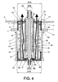
- Figure 2 shows this second blocking element in its closed position, in which a fluid is prevented from passing from inside the container, through holes 5 (see Figure 4 ) and 20, until reaching the outside through other holes 10 at the upper part of the first blocking element 1.
- the second blocking element 2 is also being pushed towards its closed position (observed in Figures 2 and 3 ) by a spring 21 arranged coaxially with the other spring 11.
- a spring 21 arranged coaxially with the other spring 11.
- One end of this spring 21 is supported on a transverse partition of the second blocking element 2, and another end of the spring is supported on an end of a threaded element 25 (by way of a "nut") which is threaded in an inner tubular wall 15 of the first blocking element 1.
- the second blocking element 2 is thus movable with respect to the first blocking element 1 against the force of the spring 21 at hand.
- the force with which the spring pushes the second blocking element towards its closed position can be preset by means of the threaded element 25.
- the spring 21 is located in a leak-tight chamber 22.
- the second blocking element has a first contact surface 2A which makes contact with the outside, and a second contact surface 2B which makes contact with the inside.
- the sizes (or their projection on the plane orthogonal to the axial movement direction) of both contact surfaces are identical. Therefore, when the internal pressure starts to exceed the external pressure, the second blocking element 2 is pressed “upwards” (towards the outside), against the force exerted by the spring 21, until reaching a position in which it no longer prevents the flow of fluid through the duct formed by the holes or passages 5, 20 and 10, as can be observed in Figure 4 . When the internal pressure decreases with respect to the external pressure, the second blocking element returns to its closed position, pushed by the spring 21.
- diameter D1A is equal to diameter D1B
- diameter D2A is equal to diameter D2B
- the leak-tightness of the chambers 12 and 22 housing the respective springs is useful for preventing the springs from making contact with fluids which may place their integrity at risk.
- the leak-tightness of these chambers requires that the walls be sized so as to withstand the forces which may be generated when a large difference between the pressure outside and inside the chambers occurs.
- Figure 5 shows a perspective view and also an exploded view of the valve, showing the details of the some of the components described above.
- the invention is not limited to the specific embodiments which have been described but also includes, for example, the variants which can be carried out by a person skilled in the art (for example, as regards the choice of materials, sizes, components, configuration, etc.), within what can be gathered from the claims.
Landscapes
- Engineering & Computer Science (AREA)
- General Engineering & Computer Science (AREA)
- Mechanical Engineering (AREA)
- Chemical & Material Sciences (AREA)
- Combustion & Propulsion (AREA)
- Ocean & Marine Engineering (AREA)
- Safety Valves (AREA)
- Filling Or Discharging Of Gas Storage Vessels (AREA)
- Table Devices Or Equipment (AREA)
- Pens And Brushes (AREA)
- External Artificial Organs (AREA)
- Pressure Vessels And Lids Thereof (AREA)
Claims (22)
- Ventil, das dazu eingerichtet ist, einen übermäßigen Druckunterschied zwischen dem Äußeren eines Containers und dem Inneren eines Containers, in dem das Ventil anzubringen ist, zu verhindern, wobei das Ventil enthält:einen ersten Ventilmechanismus, enthaltend ein erstes Absperrelement (1), das sich zwischen einer ersten Stellung, in der es einen Durchgang eines Fluids verhindert, und einer geöffneten Stellung bewegen kann, in der es den Durchgang eines Fluids zwischen dem Äußeren und dem Inneren durch einen ersten Teil (6) des Ventils gestattet; undeinen zweiten Ventilmechanismus, der ein zweites Absperrelement (2) enthält, das sich zwischen einer geschlossenen Stellung, in der es den Durchgang eines Fluids verhindert, und einer geöffneten Stellung bewegen kann, in der es den Durchgang eines Fluids zwischen dem Inneren und dem Äußeren durch einen zweiten Teil (5, 20, 10) des Ventils gestattet;wobei das erste Absperrelement (1) einem ersten Rückholelement (11) zugeordnet ist, das dazu eingerichtet ist, eine Kraft auf das erste Absperrelement in seine geschlossene Stellung auszuüben;und das zweite Absperrelement (2) einem zweiten Rückholelement (21) zugeordnet ist, das dazu eingerichtet ist, eine Kraft auf das zweite Absperrelement in seine geschlossene Stellung auszuüben;jedes Absperrelement eine erste Kontaktfläche (1 A, 2A), die dazu eingerichtet ist, einen Kontakt mit dem Äußeren des Containers herzustellen, und eine zweite Kontaktfläche (1 B, 2B) enthält, die dazu eingerichtet ist, einen Kontakt mit dem Inneren des Containers herzustellen, wenn das Ventil im Container montiert ist, so dass ein Fluid in Kontakt mit der entsprechenden Kontaktfläche eine Druckkraft auf die Kontaktfläche ausübt;der erste Ventilmechanismus dazu eingerichtet ist, dass sich das erste Absperrelement (1) von seiner geschlossenen Stellung in eine Stellung, in der es den Durchgang des Fluids gestattet, gegen die Kraft bewegt, die von dem ersten Rückholelement (11) ausgeübt wird, wenn der Druck auf seine erste Kontaktfläche (1A) X-mal größer ist als der Druck auf seine zweite Kontaktfläche (1 B), wobei X ein vorbestimmter Wert ist;und der zweite Ventilmechanismus so beschaffen ist, dass sich das zweite Absperrelement (2) aus seiner geschlossenen Stellung in eine Stellung, in der es den Durchgang des Fluids gestattet, gegen die Kraft bewegt, die von dem zweiten Rückholelement (21) ausgeübt wird, wenn der Druck auf die zweite Kontaktfläche (2B) Y-mal größer ist als der Druck auf seine erste Kontaktfläche (2A), wobei Y ein vorbestimmter Wert ist;
dadurch gekennzeichnet, dassdie Fläche der ersten Kontaktfläche (1 A) des ersten Absperrelementes identisch mit der Fläche der zweiten Kontaktfläche (1 B) des ersten Absperrelementes hinsichtlich der Projektion der Kontaktflächen auf eine Ebene ist, die orthogonal zu einer Bewegungsrichtung des ersten Absperrelementes verläuft,
und dadurch, dassdie Fläche der ersten Kontaktfläche (2A) des zweiten Absperrelementes identisch mit der Fläche der zweiten Kontaktfläche (2B) des zweiten Absperrelementes hinsichtlich der Projektion der Kontaktflächen auf eine Ebene ist, die orthogonal zur Bewegungsrichtung des zweiten Absperrelementes verläuft. - Ventil nach Anspruch 1, bei dem das erste und das zweite Rückholelement (11, 21) jeweils eine Feder enthalten.
- Ventil nach Anspruch 2, bei dem die Federn (11, 21) koaxial zueinander angeordnet sind.
- Ventil nach Anspruch 3, bei dem sich die Feder, die dem zweiten Rückholelement (21) entspricht, innerhalb der Feder befindet, die dem ersten Rückholelement (11) entspricht.
- Ventil nach einem der vorhergehenden Ansprüche, bei dem das erste Absperrelement (1) und das zweite Absperrelement (2) axial beweglich in einem röhrenförmigen Gehäuse (3) angeordnet sind.
- Ventil nach einem der vorhergehenden Ansprüche, bei dem der erste Ventilmechanismus koaxial mit dem zweiten Ventilmechanismus angeordnet ist.
- Ventil nach einem der vorhergehenden Ansprüche, bei dem die Bewegungsrichtung des ersten Absperrelementes (1) bei seiner Bewegung zwischen seiner geschlossenen Stellung und seiner geöffneten Stellung entgegengesetzt zur Bewegungsrichtung des zweiten Absperrelementes (2) bei seiner Bewegung zwischen seiner geschlossenen und seiner geöffneten Stellung ist.
- Ventil nach einem der vorhergehenden Ansprüche, bei dem sowohl die erste Kontaktfläche (1 A) als auch die zweite Kontaktfläche (1 B) des ersten Absperrelementes im wesentlichen kreisförmig sind und im wesentlichen denselben Durchmesser haben.
- Ventil nach einem der vorhergehenden Ansprüche, bei dem sowohl die erste Kontaktfläche (2A) als auch die zweite Kontaktfläche (2B) des zweiten Absperrelementes im wesentlichen kreisförmig sind und im wesentlichen denselben Durchmesser haben.
- Ventil nach einem der vorhergehenden Ansprüche, bei dem das zweite Absperrelement (2) einen Endteil, der durch die zweite Kontaktfläche (1 B) des ersten Absperrelementes ragt, und einen weiteren Endteil hat, der durch die erste Kontaktfläche (1 A) des ersten Absperrelementes ragt.
- Ventil nach einem der vorhergehenden Ansprüche, zusätzlich enthaltend Spannungs-Voreinstelleinrichtungen (4, 25), die die Spannung der Rückholelemente (11, 21) voreinstellen und eine Voreinstellung der Kraft gestatten, die die Rückholeinrichtungen auf die entsprechenden Absperrelemente in ihren jeweiligen Absperrstellungen ausüben.
- Ventil nach Anspruch 11, bei dem die Spannungs-Voreinstelleinrichtungen (4, 25) entsprechende Gewindeelemente enthalten, die derart angebracht sind, dass sie durch Drehung im Ventil axial beweglich sind.
- Ventil nach einem der vorhergehenden Ansprüche, bei dem die Rückholelemente (11, 21) in leckdichten Kammern (12, 22) im Inneren des Ventils angeordnet sind, so dass sie vor Fluiden geschützt sind, die außerhalb des Containers und innerhalb des Containers vorhanden sind, wenn das Ventil im Container montiert ist.
- Ventil nach Anspruch 13, bei dem wenigstens eine der Leckdichten Kammern (12, 22) wenigstens eine Wand hat, die mit wenigstens einem geschwächten Bereich (13, 23) versehen ist, um so ein kontrolliertes Brechen für den Fall eines übermäßigen Druckunterschiedes zwischen dem Inneren und dem Äußeren der jeweiligen leckdichten Kammer zuzulassen.
- Ventil nach einem der vorhergehenden Ansprüche, bei dem, wenn sich das erste Absperrelement (1) in seiner geöffneten Stellung befindet, Fluid von außen in das Innere des Containers durch Löcher (6) eintreten kann, die dicht an der ersten Kontaktfläche (1 A) des ersten Absperrelementes angeordnet sind.
- Ventil nach einem der vorhergehenden Ansprüche, bei dem, wenn sich das zweite Absperrelement (2) in der geöffneten Stellung befindet, Fluid vom Inneren an das Äußere des Containers durch Löcher (20) austreten kann, die in der Nähe der zweiten Kontaktfläche (1 B) des ersten Absperrelementes angeordnet sind.
- Ventil nach einem der vorhergehenden Ansprüche, bei dem das erste Absperrelement (1) in Entsprechung seiner ersten Kontaktfläche (1 A) eine Vielzahl von Löchern (10) hat, um so den Durchgang eines Fluids vom Inneren des Containers zum Äußeren zu ermöglichen, wenn das Ventil im Container montiert ist und wenn sich das zweite Absperrelement in seiner geöffneten Stellung befindet.
- Ventil nach einem der vorhergehenden Ansprüche, enthaltend einen Flansch (7), der so beschaffen ist, dass er das Ventil an der Öffnung des Containers mit Hilfe von Befestigungseinrichtungen (8, 9) befestigt.
- Container, enthaltend wenigstens ein Ventil nach einem der vorhergehenden Ansprüche.
- Container nach Anspruch 19, wobei der Container ein Container ist, der sich in einem Schiff befindet.
- Verwendung eines Ventils nach einem der Ansprüche 1 bis 18 in einem Container.
- Verwendung nach Anspruch 21, bei der sich der Container in einem Schiff befindet.
Applications Claiming Priority (1)
| Application Number | Priority Date | Filing Date | Title |
|---|---|---|---|
| ES200601182A ES2285935B1 (es) | 2003-02-27 | 2006-05-09 | Mejoras introducidas en la patente de invencion 200300479 por "sistema de equilibrado de las fuerzas que actuan sobre un contenedor hermetico durante su hundimiento en un liquido". |
Publications (2)
| Publication Number | Publication Date |
|---|---|
| EP1855037A1 EP1855037A1 (de) | 2007-11-14 |
| EP1855037B1 true EP1855037B1 (de) | 2010-03-31 |
Family
ID=38328444
Family Applications (1)
| Application Number | Title | Priority Date | Filing Date |
|---|---|---|---|
| EP07380094A Not-in-force EP1855037B1 (de) | 2006-05-09 | 2007-04-11 | Ventil, Container mit Ventil und Verwendung des Ventils |
Country Status (7)
| Country | Link |
|---|---|
| US (1) | US20100006570A1 (de) |
| EP (1) | EP1855037B1 (de) |
| JP (1) | JP2009536298A (de) |
| KR (1) | KR20090007440A (de) |
| AT (1) | ATE462912T1 (de) |
| DE (1) | DE602007005535D1 (de) |
| WO (1) | WO2007128849A1 (de) |
Families Citing this family (7)
| Publication number | Priority date | Publication date | Assignee | Title |
|---|---|---|---|---|
| GB2459683A (en) * | 2008-04-30 | 2009-11-04 | Toby Jonathan Priestly | Swelling polymer filled bag actuator |
| US8256462B2 (en) * | 2008-09-02 | 2012-09-04 | Emerson Process Management Regulator Technologies, Inc. | Fluid flow control members for use with valves |
| GB0820039D0 (en) | 2008-11-03 | 2008-12-10 | Priestly Toby J | Improvements in valves |
| WO2013085573A1 (en) * | 2011-12-07 | 2013-06-13 | Parker-Hannifin Corporation | Coupling |
| US9157297B2 (en) * | 2012-02-06 | 2015-10-13 | Halliburton Energy Services, Inc. | Pump-through fluid loss control device |
| CN113479506A (zh) * | 2021-07-16 | 2021-10-08 | 山西新华防化装备研究院有限公司 | 一种密封包装箱用呼吸阀 |
| EP4331988B1 (de) * | 2022-09-02 | 2025-03-26 | Airbus Operations GmbH | Druckloser wassertank für den betrieb in einem flugzeug, flugzeugabschnitt und flugzeug mit wassertank |
Family Cites Families (7)
| Publication number | Priority date | Publication date | Assignee | Title |
|---|---|---|---|---|
| GB1285733A (en) * | 1969-09-29 | 1972-08-16 | Lohtellier Ets | Improvements in automatic pressure equilibrating valves |
| US3868921A (en) * | 1972-06-14 | 1975-03-04 | Bowman Jon G | Normally vented liquid-storage tank for ships, with closure device for automatically preventing leaking if the ship should sink |
| NL7811148A (nl) * | 1978-11-10 | 1980-05-13 | Goris Bastiaan Pieter De Jong | Werkwijze voor het lichten van schepen, en inrichting voor het uitvoeren van de werkwijze. |
| US4294284A (en) * | 1979-11-13 | 1981-10-13 | Smith International, Inc. | Fail-safe, non-pressure locking gate valve |
| US5282492A (en) * | 1993-02-23 | 1994-02-01 | The United States Of America As Represented By The Secretary Of The Navy | Dual valve plate two-way pressure relief valve |
| DE4408357A1 (de) * | 1994-03-14 | 1995-09-21 | Ralf Dr Ing Teichmann | Sicherheitsventil zum Sichern von Behältern gegen Über- oder Unterdruck |
| US7086388B2 (en) * | 2003-08-04 | 2006-08-08 | Delphi Technologies, Inc. | Combination valve for fuel system |
-
2007
- 2007-04-11 JP JP2009508398A patent/JP2009536298A/ja active Pending
- 2007-04-11 KR KR1020087027856A patent/KR20090007440A/ko not_active Withdrawn
- 2007-04-11 DE DE602007005535T patent/DE602007005535D1/de active Active
- 2007-04-11 AT AT07380094T patent/ATE462912T1/de not_active IP Right Cessation
- 2007-04-11 WO PCT/ES2007/000210 patent/WO2007128849A1/es not_active Ceased
- 2007-04-11 US US12/300,294 patent/US20100006570A1/en not_active Abandoned
- 2007-04-11 EP EP07380094A patent/EP1855037B1/de not_active Not-in-force
Also Published As
| Publication number | Publication date |
|---|---|
| ATE462912T1 (de) | 2010-04-15 |
| WO2007128849A1 (es) | 2007-11-15 |
| KR20090007440A (ko) | 2009-01-16 |
| DE602007005535D1 (de) | 2010-05-12 |
| EP1855037A1 (de) | 2007-11-14 |
| US20100006570A1 (en) | 2010-01-14 |
| JP2009536298A (ja) | 2009-10-08 |
Similar Documents
| Publication | Publication Date | Title |
|---|---|---|
| US20100006570A1 (en) | Valve, container with valve and use of the valve | |
| US7357151B2 (en) | Fluid control devices | |
| JP5369400B2 (ja) | 流量制御弁 | |
| US6131599A (en) | Rupture disk controlled mechanically actuated pressure relief valve assembly | |
| CN102498447A (zh) | 平衡阀芯 | |
| CN107795697B (zh) | 用于流体调节器的稳定器筒 | |
| KR102492002B1 (ko) | 온도 감응형 퀵 클로징 게이트 밸브 조립체 | |
| WO2019040060A1 (en) | BALANCING LINE SAFETY VALVE | |
| US10208866B2 (en) | Relief valve | |
| BRPI0918477B1 (pt) | gatilho e elemento de controle de fluxo de fluido | |
| US10704804B2 (en) | System, device and associated methods for protection during over-temperature and over-pressure in a water heater | |
| KR860007149A (ko) | 안전 유동 조절장치 | |
| EP2960560B1 (de) | Hochintegriertes Druckschutzsystem für eine Fluidleitung | |
| WO2015113789A1 (en) | Valve for a subsea pressure canister | |
| KR101551474B1 (ko) | 수동밸브 기능이 구비된 안전밸브 | |
| CN101443585A (zh) | 阀门和带有阀门的容器及该阀门的用途 | |
| US10408496B2 (en) | System, device and associated methods for temperature and pressure relief in a water heater | |
| RU2249138C2 (ru) | Устройство отсекающее | |
| RU2311580C2 (ru) | Регулирующий клапан с каналом проверки стравливания давления | |
| US11193603B2 (en) | Pressure relief valve | |
| US5931190A (en) | Relief valve | |
| US4497338A (en) | Relief valve | |
| RU185972U1 (ru) | Отсекающий клапан | |
| RU2064098C1 (ru) | Устройство для ограничения расхода жидкости | |
| US20120234416A1 (en) | Pilot Regulator |
Legal Events
| Date | Code | Title | Description |
|---|---|---|---|
| PUAI | Public reference made under article 153(3) epc to a published international application that has entered the european phase |
Free format text: ORIGINAL CODE: 0009012 |
|
| AK | Designated contracting states |
Kind code of ref document: A1 Designated state(s): AT BE BG CH CY CZ DE DK EE ES FI FR GB GR HU IE IS IT LI LT LU LV MC MT NL PL PT RO SE SI SK TR |
|
| AX | Request for extension of the european patent |
Extension state: AL BA HR MK YU |
|
| 17P | Request for examination filed |
Effective date: 20080314 |
|
| AKX | Designation fees paid |
Designated state(s): AT BE BG CH CY CZ DE DK EE ES FI FR GB GR HU IE IS IT LI LT LU LV MC MT NL PL PT RO SE SI SK TR |
|
| 17Q | First examination report despatched |
Effective date: 20081119 |
|
| GRAP | Despatch of communication of intention to grant a patent |
Free format text: ORIGINAL CODE: EPIDOSNIGR1 |
|
| GRAS | Grant fee paid |
Free format text: ORIGINAL CODE: EPIDOSNIGR3 |
|
| GRAA | (expected) grant |
Free format text: ORIGINAL CODE: 0009210 |
|
| AK | Designated contracting states |
Kind code of ref document: B1 Designated state(s): AT BE BG CH CY CZ DE DK EE ES FI FR GB GR HU IE IS IT LI LT LU LV MC MT NL PL PT RO SE SI SK TR |
|
| REG | Reference to a national code |
Ref country code: CH Ref legal event code: EP Ref country code: GB Ref legal event code: FG4D |
|
| REG | Reference to a national code |
Ref country code: IE Ref legal event code: FG4D |
|
| REF | Corresponds to: |
Ref document number: 602007005535 Country of ref document: DE Date of ref document: 20100512 Kind code of ref document: P |
|
| REG | Reference to a national code |
Ref country code: NL Ref legal event code: VDEP Effective date: 20100331 |
|
| PG25 | Lapsed in a contracting state [announced via postgrant information from national office to epo] |
Ref country code: LT Free format text: LAPSE BECAUSE OF FAILURE TO SUBMIT A TRANSLATION OF THE DESCRIPTION OR TO PAY THE FEE WITHIN THE PRESCRIBED TIME-LIMIT Effective date: 20100331 |
|
| LTIE | Lt: invalidation of european patent or patent extension |
Effective date: 20100331 |
|
| PG25 | Lapsed in a contracting state [announced via postgrant information from national office to epo] |
Ref country code: FI Free format text: LAPSE BECAUSE OF FAILURE TO SUBMIT A TRANSLATION OF THE DESCRIPTION OR TO PAY THE FEE WITHIN THE PRESCRIBED TIME-LIMIT Effective date: 20100331 Ref country code: LV Free format text: LAPSE BECAUSE OF FAILURE TO SUBMIT A TRANSLATION OF THE DESCRIPTION OR TO PAY THE FEE WITHIN THE PRESCRIBED TIME-LIMIT Effective date: 20100331 Ref country code: PL Free format text: LAPSE BECAUSE OF FAILURE TO SUBMIT A TRANSLATION OF THE DESCRIPTION OR TO PAY THE FEE WITHIN THE PRESCRIBED TIME-LIMIT Effective date: 20100331 Ref country code: SI Free format text: LAPSE BECAUSE OF FAILURE TO SUBMIT A TRANSLATION OF THE DESCRIPTION OR TO PAY THE FEE WITHIN THE PRESCRIBED TIME-LIMIT Effective date: 20100331 Ref country code: AT Free format text: LAPSE BECAUSE OF FAILURE TO SUBMIT A TRANSLATION OF THE DESCRIPTION OR TO PAY THE FEE WITHIN THE PRESCRIBED TIME-LIMIT Effective date: 20100331 |
|
| PG25 | Lapsed in a contracting state [announced via postgrant information from national office to epo] |
Ref country code: CY Free format text: LAPSE BECAUSE OF FAILURE TO SUBMIT A TRANSLATION OF THE DESCRIPTION OR TO PAY THE FEE WITHIN THE PRESCRIBED TIME-LIMIT Effective date: 20100331 Ref country code: ES Free format text: LAPSE BECAUSE OF FAILURE TO SUBMIT A TRANSLATION OF THE DESCRIPTION OR TO PAY THE FEE WITHIN THE PRESCRIBED TIME-LIMIT Effective date: 20100712 Ref country code: EE Free format text: LAPSE BECAUSE OF FAILURE TO SUBMIT A TRANSLATION OF THE DESCRIPTION OR TO PAY THE FEE WITHIN THE PRESCRIBED TIME-LIMIT Effective date: 20100331 Ref country code: BE Free format text: LAPSE BECAUSE OF FAILURE TO SUBMIT A TRANSLATION OF THE DESCRIPTION OR TO PAY THE FEE WITHIN THE PRESCRIBED TIME-LIMIT Effective date: 20100331 Ref country code: SE Free format text: LAPSE BECAUSE OF FAILURE TO SUBMIT A TRANSLATION OF THE DESCRIPTION OR TO PAY THE FEE WITHIN THE PRESCRIBED TIME-LIMIT Effective date: 20100331 Ref country code: RO Free format text: LAPSE BECAUSE OF FAILURE TO SUBMIT A TRANSLATION OF THE DESCRIPTION OR TO PAY THE FEE WITHIN THE PRESCRIBED TIME-LIMIT Effective date: 20100331 Ref country code: NL Free format text: LAPSE BECAUSE OF FAILURE TO SUBMIT A TRANSLATION OF THE DESCRIPTION OR TO PAY THE FEE WITHIN THE PRESCRIBED TIME-LIMIT Effective date: 20100331 |
|
| PG25 | Lapsed in a contracting state [announced via postgrant information from national office to epo] |
Ref country code: SK Free format text: LAPSE BECAUSE OF FAILURE TO SUBMIT A TRANSLATION OF THE DESCRIPTION OR TO PAY THE FEE WITHIN THE PRESCRIBED TIME-LIMIT Effective date: 20100331 Ref country code: MC Free format text: LAPSE BECAUSE OF NON-PAYMENT OF DUE FEES Effective date: 20100430 Ref country code: IS Free format text: LAPSE BECAUSE OF FAILURE TO SUBMIT A TRANSLATION OF THE DESCRIPTION OR TO PAY THE FEE WITHIN THE PRESCRIBED TIME-LIMIT Effective date: 20100731 Ref country code: CZ Free format text: LAPSE BECAUSE OF FAILURE TO SUBMIT A TRANSLATION OF THE DESCRIPTION OR TO PAY THE FEE WITHIN THE PRESCRIBED TIME-LIMIT Effective date: 20100331 |
|
| PG25 | Lapsed in a contracting state [announced via postgrant information from national office to epo] |
Ref country code: DK Free format text: LAPSE BECAUSE OF FAILURE TO SUBMIT A TRANSLATION OF THE DESCRIPTION OR TO PAY THE FEE WITHIN THE PRESCRIBED TIME-LIMIT Effective date: 20100331 Ref country code: IE Free format text: LAPSE BECAUSE OF NON-PAYMENT OF DUE FEES Effective date: 20100411 Ref country code: PT Free format text: LAPSE BECAUSE OF FAILURE TO SUBMIT A TRANSLATION OF THE DESCRIPTION OR TO PAY THE FEE WITHIN THE PRESCRIBED TIME-LIMIT Effective date: 20100802 |
|
| PLBE | No opposition filed within time limit |
Free format text: ORIGINAL CODE: 0009261 |
|
| STAA | Information on the status of an ep patent application or granted ep patent |
Free format text: STATUS: NO OPPOSITION FILED WITHIN TIME LIMIT |
|
| PGFP | Annual fee paid to national office [announced via postgrant information from national office to epo] |
Ref country code: DE Payment date: 20101022 Year of fee payment: 4 |
|
| 26N | No opposition filed |
Effective date: 20110104 |
|
| PG25 | Lapsed in a contracting state [announced via postgrant information from national office to epo] |
Ref country code: IT Free format text: LAPSE BECAUSE OF FAILURE TO SUBMIT A TRANSLATION OF THE DESCRIPTION OR TO PAY THE FEE WITHIN THE PRESCRIBED TIME-LIMIT Effective date: 20100331 |
|
| PG25 | Lapsed in a contracting state [announced via postgrant information from national office to epo] |
Ref country code: MT Free format text: LAPSE BECAUSE OF FAILURE TO SUBMIT A TRANSLATION OF THE DESCRIPTION OR TO PAY THE FEE WITHIN THE PRESCRIBED TIME-LIMIT Effective date: 20100331 |
|
| PGFP | Annual fee paid to national office [announced via postgrant information from national office to epo] |
Ref country code: GB Payment date: 20110801 Year of fee payment: 5 |
|
| REG | Reference to a national code |
Ref country code: CH Ref legal event code: PL |
|
| REG | Reference to a national code |
Ref country code: FR Ref legal event code: ST Effective date: 20111125 |
|
| PG25 | Lapsed in a contracting state [announced via postgrant information from national office to epo] |
Ref country code: CH Free format text: LAPSE BECAUSE OF NON-PAYMENT OF DUE FEES Effective date: 20110430 Ref country code: DE Free format text: LAPSE BECAUSE OF NON-PAYMENT OF DUE FEES Effective date: 20111101 Ref country code: LI Free format text: LAPSE BECAUSE OF NON-PAYMENT OF DUE FEES Effective date: 20110430 Ref country code: FR Free format text: LAPSE BECAUSE OF NON-PAYMENT OF DUE FEES Effective date: 20100531 |
|
| REG | Reference to a national code |
Ref country code: DE Ref legal event code: R119 Ref document number: 602007005535 Country of ref document: DE Effective date: 20111101 |
|
| PG25 | Lapsed in a contracting state [announced via postgrant information from national office to epo] |
Ref country code: LU Free format text: LAPSE BECAUSE OF NON-PAYMENT OF DUE FEES Effective date: 20100411 Ref country code: HU Free format text: LAPSE BECAUSE OF FAILURE TO SUBMIT A TRANSLATION OF THE DESCRIPTION OR TO PAY THE FEE WITHIN THE PRESCRIBED TIME-LIMIT Effective date: 20101001 Ref country code: BG Free format text: LAPSE BECAUSE OF FAILURE TO SUBMIT A TRANSLATION OF THE DESCRIPTION OR TO PAY THE FEE WITHIN THE PRESCRIBED TIME-LIMIT Effective date: 20100331 |
|
| PG25 | Lapsed in a contracting state [announced via postgrant information from national office to epo] |
Ref country code: TR Free format text: LAPSE BECAUSE OF FAILURE TO SUBMIT A TRANSLATION OF THE DESCRIPTION OR TO PAY THE FEE WITHIN THE PRESCRIBED TIME-LIMIT Effective date: 20100331 |
|
| GBPC | Gb: european patent ceased through non-payment of renewal fee |
Effective date: 20120411 |
|
| PG25 | Lapsed in a contracting state [announced via postgrant information from national office to epo] |
Ref country code: GB Free format text: LAPSE BECAUSE OF NON-PAYMENT OF DUE FEES Effective date: 20120411 |
|
| PG25 | Lapsed in a contracting state [announced via postgrant information from national office to epo] |
Ref country code: BG Free format text: LAPSE BECAUSE OF FAILURE TO SUBMIT A TRANSLATION OF THE DESCRIPTION OR TO PAY THE FEE WITHIN THE PRESCRIBED TIME-LIMIT Effective date: 20100630 |
|
| PG25 | Lapsed in a contracting state [announced via postgrant information from national office to epo] |
Ref country code: GR Free format text: LAPSE BECAUSE OF FAILURE TO SUBMIT A TRANSLATION OF THE DESCRIPTION OR TO PAY THE FEE WITHIN THE PRESCRIBED TIME-LIMIT Effective date: 20100331 |