EP1854691A1 - Bridge with turntable for the intersection of two vehicles with a jointed connection - Google Patents
Bridge with turntable for the intersection of two vehicles with a jointed connection Download PDFInfo
- Publication number
- EP1854691A1 EP1854691A1 EP07009125A EP07009125A EP1854691A1 EP 1854691 A1 EP1854691 A1 EP 1854691A1 EP 07009125 A EP07009125 A EP 07009125A EP 07009125 A EP07009125 A EP 07009125A EP 1854691 A1 EP1854691 A1 EP 1854691A1
- Authority
- EP
- European Patent Office
- Prior art keywords
- turntable
- vehicle
- bridge according
- transition
- intermediate member
- Prior art date
- Legal status (The legal status is an assumption and is not a legal conclusion. Google has not performed a legal analysis and makes no representation as to the accuracy of the status listed.)
- Granted
Links
- 230000007704 transition Effects 0.000 claims description 33
- 230000008878 coupling Effects 0.000 claims 1
- 238000010168 coupling process Methods 0.000 claims 1
- 238000005859 coupling reaction Methods 0.000 claims 1
- 229920001971 elastomer Polymers 0.000 abstract description 2
- 238000005452 bending Methods 0.000 description 2
- 238000005096 rolling process Methods 0.000 description 2
- 238000010276 construction Methods 0.000 description 1
- 238000006073 displacement reaction Methods 0.000 description 1
- 239000000806 elastomer Substances 0.000 description 1
- 238000004904 shortening Methods 0.000 description 1
- 239000002689 soil Substances 0.000 description 1
Images


Classifications
-
- B—PERFORMING OPERATIONS; TRANSPORTING
- B61—RAILWAYS
- B61D—BODY DETAILS OR KINDS OF RAILWAY VEHICLES
- B61D17/00—Construction details of vehicle bodies
- B61D17/04—Construction details of vehicle bodies with bodies of metal; with composite, e.g. metal and wood body structures
- B61D17/20—Communication passages between coaches; Adaptation of coach ends therefor
-
- B—PERFORMING OPERATIONS; TRANSPORTING
- B61—RAILWAYS
- B61D—BODY DETAILS OR KINDS OF RAILWAY VEHICLES
- B61D3/00—Wagons or vans
- B61D3/10—Articulated vehicles
Definitions
- the present invention relates to a bridge with a hub of a transition between two interconnected by a joint vehicles.
- Articulately interconnected vehicles are, for example in the form of articulated buses, but also in the form of rail vehicles, z. B. trams, known.
- Rail vehicles, and in particular trams have a plurality of bogies, in the bogies, ie in front of or behind the bogies, the individual vehicles or vehicle parts are connected by joints.
- the transition comprises a transition bridge and a bellows, which is known to encompass both the transition bridge and the joint to the persons in the vehicle the transition from one vehicle to the other vehicle, exposed to the weather to be possible.
- articulated vehicles must be able to follow the most varied movements during their journey.
- a vehicle must enable kinking movements, such as occur when such a vehicle drives through a curve.
- pitching movements must be made possible, as occur when such a vehicle travels over a crest or through a depression.
- rolling movements should also be able to be accommodated, as occur, for example, when the vehicles are rotated against one another.
- the described movements can also occur superimposed on each other.
- in the area of a turntable arise when cornering, so with a bending movement and possibly superimposed rolling and pitching movements, extremely complex movements in the hub, for example, if one considers a point on the outer circumference of the turntable.
- Modern tram trains are especially designed so that they also allow wheelchair users the opportunity to get directly from the platform edge in the vehicle, possibly also by means of a ramp in the door entry in the sense of barrier-free access.
- the vehicles are designed low-floor at least in the area of an entry.
- limits are set in the range of the rotary joint, since the hinge can not fall below a certain minimum height.
- the hub extends obliquely over the joint, wherein the inclined turntable is connected at its other end to the vehicle floor of a vehicle in combination
- connection from the hub to the bottom of the vehicle can be done directly, or indirectly by a dome plate.
- a dome plate may be provided which is rigidly connected to the ground.
- the turntable is held clamped in the transition to the bottom of a vehicle.
- the turntable rotates when cornering relative to the vehicle floor and thus has on its the bottom of a vehicle part facing end face on a circular arc-shaped training.
- the parts forming the bridge are arranged displaceably parallel to the longitudinal axis of the vehicle, in particular the hub is slidably clamped along its front-side circumference relative to the bottom of a vehicle parallel to the longitudinal axis of the vehicle. This means that the turntable can move relative to the ground in the vehicle's longitudinal axis.
- a clamping bar is provided which covers the edge region of the hub and the dome plate, and which is connected to a counter ledge below the turntable and the dome plate.
- the hub In order to ensure that even when loading the clamping bar, the hub can easily rotate, is provided between clamping bar and turntable and a slide bar, for example made of plastic.
- An equal sliding strip is also advantageous between the Counter ledge on the one hand and the turntable and the dome plate on the other hand arranged.
- the elastic intermediate member which is designed in particular as a plate is connected by connecting strips with each of the vehicle floor and the turntable.
- a dome plate can also be provided between the bottom of the other vehicle and the elastic intermediate member, this dome plate is connected on the one hand with the elastic intermediate member and on the other hand to the vehicle floor of the other vehicle. It should again be noted at this point that it is essentially irrelevant to the invention whether the vehicle floor is directly connected to the turntable or the elastic intermediate member or by a dome plate.
- the end edge of the turntable extends in the transition to the elastic intermediate member through the pivot point of the joint. It is also provided that the bottom of the other vehicle is formed arrow-shaped extending in the transition to the elastic intermediate member, wherein the elastic intermediate member extends corresponding thereto.
- the tram line marked 1 comprises the three vehicles 2, 3 and 4, which communicate with each other through the transitions 5.
- the Schienengelenkzug the two bogies 6. If such a vehicle drives around a curve, for example, then the tram train follows the course of the curve by bending in the region of the transitions 5.
- transition bridge 10 as part of the total designated 5 transition (Fig. 2 ff).
- the transition bridge 10 comprising the hub 20, the elastic intermediate member 30 and the dome plate 40 and the dome plate 50 is located obliquely over the joint designated 60 for connection of the two vehicles 3, as can be seen in FIG.
- the transition bridge as well as the joint 60 is surrounded by the bellows designated overall by 15, as this results in particular in view of FIGS. 2 and 3. It can be seen in particular from FIG. 3 that the end edge 21 of the turntable 20 extends through the pivot point 61 of the joint 60.
- the dome plate 40 is formed in the direction of the terminal edge 21 to arrow-shaped (arrow 45), the tip of the arrow-shaped dome plate centric on the pivot point (61) of the Assigns joint 60.
- the elastic intermediate member 30 ultimately follows the course of both the turntable in this area and the dome plate 40.
- Such a design of the elastic intermediate member has proven to be advantageous insofar as this design in the central region of this elastic intermediate member, the lowest stresses occur.
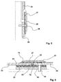
- FIG. 5 As a section of the line V - V of Figure 4, it can be seen as well as from Figure 6, the clamping of the hub 20 through the dome plate 50. Specifically, this is a clamping bar 25 is provided, wherein the clamping bar 25 by circularly arranged screws 26 is connected to the dome plate 50. Between the clamping bar 25 and the turntable 20 on the one hand and the dome plate on the other hand there is a slide bar 27 to ensure a relative movement of the hub 20 to the dome plate 50 and thus ultimately to the bottom of the coupled vehicle.
- the dome plate 50 is connected to the counter-bar 55 by screws 56 there. Again, located between the hub 20 and the dome plate 50 on the one hand and the counter ledge 55 on the other hand, a slide bar 57 to the relative movement of the hub 20 on the one hand to the counter ledge 55, which - as already stated - rigidly connected to the dome plate 50 by the screws 56 is to ensure.
- a gap 70 recognizable is between the end face 22, the hub 20 and the end face 53 of the dome plate 50, a gap 75 recognizable, with a gap 75 also in the clamping bar 25, and here in particular between the front edge of the slide bar 27 and a stage 23 of the hub 20th is provided, wherein the two columns serve to allow a pitching movement of the vehicles connected in this way.
- the connection of the elastic intermediate member 30 with the dome plate 40 on the one hand and the turntable 20 on the other hand is shown in Figure 7.
- the elastic intermediate member 30, which consists of an elastomer or an elastic plastic, is screwed by the connecting strips 35 each with the dome plate 60 and the hub 20.
- the elastic intermediate member 30 has on its upper side a wear-resistant surface 31, which can be accomplished in particular by the support of a thin sheet.
Landscapes
- Engineering & Computer Science (AREA)
- Mechanical Engineering (AREA)
- Transportation (AREA)
- Life Sciences & Earth Sciences (AREA)
- Wood Science & Technology (AREA)
- Vehicle Cleaning, Maintenance, Repair, Refitting, And Outriggers (AREA)
- Body Structure For Vehicles (AREA)
- Road Signs Or Road Markings (AREA)
- Vehicle Step Arrangements And Article Storage (AREA)
- Automobile Manufacture Line, Endless Track Vehicle, Trailer (AREA)
- Shaping Metal By Deep-Drawing, Or The Like (AREA)
- Specific Conveyance Elements (AREA)
- Mechanical Operated Clutches (AREA)
Abstract
Description
Die vorliegende Erfindung betrifft eine Brücke mit Drehscheibe eines Übergangs zwischen zwei durch ein Gelenk miteinander verbundenen Fahrzeugen.The present invention relates to a bridge with a hub of a transition between two interconnected by a joint vehicles.
Gelenkig miteinander verbundene Fahrzeuge sind beispielsweise in Form von Gelenkbussen, aber auch in Form von schienengebundenen Fahrzeugen, z. B. Straßenbahnen, bekannt. Schienenfahrzeuge, und hier insbesondere Straßenbahnen, weisen mehrere Drehgestelle auf, wobei im Bereich der Drehgestelle, also vor oder hinter den Drehgestellen, die einzelnen Fahrzeuge oder Fahrzeugteile durch Gelenke miteinander verbunden sind. Im Bereich der Gelenke befindet sich ein Übergang, wobei der Übergang eine Übergangsbrücke umfasst sowie einen Balg, der bekannterweise sowohl die Übergangsbrücke als auch das Gelenk umspannt, um den in dem Fahrzeug befindlichen Personen den Übergang von einem Fahrzeug in das andere Fahrzeug, ohne Witterungseinflüssen ausgesetzt zu sein, zu ermöglichen.Articulately interconnected vehicles are, for example in the form of articulated buses, but also in the form of rail vehicles, z. B. trams, known. Rail vehicles, and in particular trams, have a plurality of bogies, in the bogies, ie in front of or behind the bogies, the individual vehicles or vehicle parts are connected by joints. In the area of the joints is a transition, wherein the transition comprises a transition bridge and a bellows, which is known to encompass both the transition bridge and the joint to the persons in the vehicle the transition from one vehicle to the other vehicle, exposed to the weather to be possible.
Bekanntermaßen müssen Gelenkfahrzeuge bei ihrer Fahrt den unterschiedlichsten Bewegungen folgen können. So muss ein solches Fahrzeug insbesondere Knickbewegungen ermöglichen, wie sie auftreten, wenn ein solches Fahrzeug durch eine Kurve fährt. Darüber hinaus müssen Nickbewegungen ermöglicht werden, wie sie auftreten, wenn ein solches Fahrzeug über eine Kuppe oder durch eine Senke fährt. Im gewissen Umfang sollen auch Wankbewegungen aufgenommen werden können, wie sie beispielsweise auftreten, wenn die Fahrzeuge gegeneinander verdreht werden. Darüber hinaus ist zu beachten, dass die beschriebenen Bewegungen auch einander überlagert auftreten können. Insbesondere im Bereich einer Drehscheibe ergeben sich bei Kurvenfahrt, also bei einer Knickbewegung und gegebenenfalls überlagerten Wank- und Nickbewegungen, überaus komplexe Bewegungsabläufe im Bereich der Drehscheibe, wenn man beispielsweise einen Punkt auf dem äußeren Umfang der Drehscheibe betrachtet.As is known, articulated vehicles must be able to follow the most varied movements during their journey. In particular, such a vehicle must enable kinking movements, such as occur when such a vehicle drives through a curve. In addition, pitching movements must be made possible, as occur when such a vehicle travels over a crest or through a depression. To a certain extent, rolling movements should also be able to be accommodated, as occur, for example, when the vehicles are rotated against one another. In addition, it should be noted that the described movements can also occur superimposed on each other. In particular, in the area of a turntable arise when cornering, so with a bending movement and possibly superimposed rolling and pitching movements, extremely complex movements in the hub, for example, if one considers a point on the outer circumference of the turntable.
Durch die Verbindung der Drehscheibe mit ihrem einen Ende durch ein elastisches Zwischenglied mit dem Boden des einen Fahrzeugs wird erfindungsgemäß gewährleistet, dass auch solche komplexen Bewegungsabläufe ohne Schaden für die Drehscheibe ausgeführt werden können, da die hierbei auftretenden Bewegungen von dem elastischen Zwischenglied aufgenommen werden.By connecting the hub with its one end by an elastic intermediate member to the bottom of a vehicle is ensured according to the invention that even such complex Movements can be performed without damage to the hub, since the movements occurring here are absorbed by the elastic intermediate member.
Moderne Straßenbahnzüge sind insbesondere derart konstruiert, dass sie im Sinne eines barrierefreien Zugangs auch Rollstuhlfahrern die Möglichkeit eröffnen, unmittelbar von der Bahnsteigkante in das Fahrzeug zu gelangen, gegebenenfalls auch mittels einer Rampe im Türeinstieg. Hierfür sind die Fahrzeuge zumindest im Bereich eines Einstiegs niederflurig ausgebildet. Einer solchen Niederflurigkeit sind allerdings Grenzen im Bereich des Drehgelenkes gesetzt, da das Drehgelenk eine gewisse Mindestbauhöhe nicht unterschreiten kann. Um nun einen barrierefreien Übergang zwischen den einzelnen Fahrzeugen eines solchen Gelenkzuges zu ermöglichen, wird weiterhin vorgeschlagen, dass die Drehscheibe über dem Gelenk schräg stehend verläuft, wobei die schräg stehende Drehscheibe an ihrem anderen Ende mit dem Fahrzeugboden des einen Fahrzeugs in Verbindung stehtModern tram trains are especially designed so that they also allow wheelchair users the opportunity to get directly from the platform edge in the vehicle, possibly also by means of a ramp in the door entry in the sense of barrier-free access. For this purpose, the vehicles are designed low-floor at least in the area of an entry. Such a low-floor, however, limits are set in the range of the rotary joint, since the hinge can not fall below a certain minimum height. In order to enable a barrier-free transition between the individual vehicles of such a hinge, it is further proposed that the hub extends obliquely over the joint, wherein the inclined turntable is connected at its other end to the vehicle floor of a vehicle in combination
Die Anbindung von der Drehscheibe zum Boden des Fahrzeugs kann unmittelbar, oder auch mittelbar durch eine Kuppelplatte erfolgen. Gleiches gilt sinngemäß auch für den Übergang von dem elastischen Zwischenglied zum Fahrzeugboden. Auch hier kann eine Kuppelplatte vorgesehen sein, die starr mit dem Boden verbunden ist.The connection from the hub to the bottom of the vehicle can be done directly, or indirectly by a dome plate. The same applies mutatis mutandis to the transition from the elastic intermediate member to the vehicle floor. Again, a dome plate may be provided which is rigidly connected to the ground.
Um zu verhindern, dass sich bei Bewegung der Fahrzeuge relativ zueinander die Drehscheibe gegenüber dem Boden des Fahrzeugs abhebt oder absenkt, ist nach einem weiteren Merkmal der Erfindung vorgesehen, dass die Drehscheibe im Übergang zum Boden des einen Fahrzeugs eingespannt gehalten ist. Wie bereits an anderer Stelle erläutert, dreht sich die Drehscheibe bei Kurvenfahrt relativ zum Fahrzeugboden und weist insofern auf ihrer dem Boden des einen Fahrzeugsteils zugewandten Stirnseite eine kreisbogenförmige Ausbildung auf. Durch die eingespannte Halterung der Drehscheibe im Übergangsbereich zum Boden des einen Fahrzeugteils wird nun erreicht, dass sich die Drehscheibe zwar innerhalb dieser Einspannung relativ zum Boden verdrehen kann, sich diese allerdings nicht abheben oder absenken kann.In order to prevent that when moving the vehicles relative to each other, the turntable with respect to the floor of the vehicle lifts or lowers, is provided according to a further feature of the invention that the turntable is held clamped in the transition to the bottom of a vehicle. As already explained elsewhere, the turntable rotates when cornering relative to the vehicle floor and thus has on its the bottom of a vehicle part facing end face on a circular arc-shaped training. By the clamped Holding the turntable in the transition region to the bottom of a vehicle part is now achieved that the turntable can indeed rotate within this clamping relative to the ground, but this can not stand out or lower.
Ebenfalls an anderer Stelle wurde bereits erläutert, dass die Fahrzeuge auch Nickbewegungen ausführen können müssen, wie sie auftreten, wenn solche Fahrzeuge über Kuppen oder durch Senken fahren. Insofern ist vorgesehen, dass die die Brücke bildenden Teile parallel zur Längsachse des Fahrzeugs verschieblich angeordnet sind, insbesondere ist die Drehscheibe entlang ihres stirnseitigen Umfangs relativ zum Boden des einen Fahrzeugs parallel zur Längsachse des Fahrzeugs verschieblich eingespannt gehalte. Das bedeutet, dass sich die Drehscheibe relativ zum Boden in Fahrzeugslängsachse verschieben kann. Um eine solche Einspannung zu bewerkstelligen ist im Einzelnen weiterhin vorgesehen, dass zwischen der Stirnseite der Drehscheibe und dem Boden oder Kuppelplatte ein umlaufender Spalt vorgesehen, wobei zur eingespannten Halterung der Drehscheibe eine Spannleiste vorgesehen ist, die den Randbereich der Drehscheibe und der Kuppelplatte überdeckt, und die mit einer Konterleiste unter der Drehscheibe und der Kuppelplatte verbunden ist.It has also been explained elsewhere that the vehicles must also be able to execute pitching movements as they occur when such vehicles drive over crests or through depressions. In this respect, it is provided that the parts forming the bridge are arranged displaceably parallel to the longitudinal axis of the vehicle, in particular the hub is slidably clamped along its front-side circumference relative to the bottom of a vehicle parallel to the longitudinal axis of the vehicle. This means that the turntable can move relative to the ground in the vehicle's longitudinal axis. In order to accomplish such a clamping is further provided in detail that between the front side of the hub and the bottom or dome plate provided a circumferential gap, wherein the clamped mounting of the hub, a clamping bar is provided which covers the edge region of the hub and the dome plate, and which is connected to a counter ledge below the turntable and the dome plate.
In diesem Zusammenhang ist darauf hinzuweisen, dass die Anordnung eines solchen Spaltes grundsätzlich auch im Übergang zum Boden des anderen Fahrzeugs möglich ist. Wesentlich ist allein die Möglichkeit der Verschiebung der Brücke oder auch von Teilen der Brücke, um eine solchen Verkürzung oder Verlängerung der Brücke zu ermöglichen.In this context, it should be noted that the arrangement of such a gap is basically possible in the transition to the floor of the other vehicle. It is essential only the possibility of displacement of the bridge or parts of the bridge to allow such a shortening or extension of the bridge.
Um nun zu gewährleisten, dass sich auch bei Belastung der Spannleiste die Drehscheibe problemlos verdrehen kann, ist zwischen Spannleiste und Drehscheibe und eine Gleitleiste, beispielsweise aus Kunststoff, vorgesehen. Eine ebensolche Gleitleiste ist vorteilhaft auch zwischen der Konterleiste einerseits und der Drehscheibe und der Kuppelplatte anderseits angeordnet.In order to ensure that even when loading the clamping bar, the hub can easily rotate, is provided between clamping bar and turntable and a slide bar, for example made of plastic. An equal sliding strip is also advantageous between the Counter ledge on the one hand and the turntable and the dome plate on the other hand arranged.
Das elastische Zwischenglied, das insbesondere als Platte ausgebildet ist, ist durch Verbindungsleisten mit jeweils dem Fahrzeugboden und der Drehscheibe verbunden. Vorteilhaft kann auch hierbei zwischen dem Boden des anderen Fahrzeugs und dem elastischen Zwischenglied eine Kuppelplatte vorgesehen sein, wobei diese Kuppelplatte einerseits mit dem elastischen Zwischenglied und andererseits mit dem Fahrzeugboden des anderen Fahrzeugs verbunden ist. Es sei an dieser Stelle noch einmal darauf hingewiesen, dass es für die Erfindung im Wesentlichen ohne Auswirkung ist, ob der Fahrzeugboden unmittelbar mit der Drehscheibe oder dem elastischen Zwischenglied oder durch eine Kuppelplatte verbunden ist.The elastic intermediate member, which is designed in particular as a plate is connected by connecting strips with each of the vehicle floor and the turntable. Advantageously, a dome plate can also be provided between the bottom of the other vehicle and the elastic intermediate member, this dome plate is connected on the one hand with the elastic intermediate member and on the other hand to the vehicle floor of the other vehicle. It should again be noted at this point that it is essentially irrelevant to the invention whether the vehicle floor is directly connected to the turntable or the elastic intermediate member or by a dome plate.
Nach einem weiteren Merkmal der Erfindung ist vorgesehen, dass die Abschlusskante der Drehscheibe im Übergang zum elastischen Zwischenglied durch den Drehpunkt des Gelenkes verläuft. Ebenfalls ist vorgesehen, dass der Boden des anderen Fahrzeugs im Übergang zum elastischen Zwischenglied pfeilförmig verlaufend ausgebildet ist, wobei das elastische Zwischenglied korrespondierend hierzu verläuft. Die Spitze des pfeilförmigen Verlaufes des Bodens, oder für den Fall, dass eine Kuppelplatte Anwendung findet auch die Kuppelplatte, endet hierbei im Bereich des Drehpunktes des Drehgelenkes, das die beiden Fahrzeuge miteinander gelenkig verbindet.According to a further feature of the invention, it is provided that the end edge of the turntable extends in the transition to the elastic intermediate member through the pivot point of the joint. It is also provided that the bottom of the other vehicle is formed arrow-shaped extending in the transition to the elastic intermediate member, wherein the elastic intermediate member extends corresponding thereto. The tip of the arrow-shaped course of the soil, or in the event that a dome plate finds application also the dome plate, this ends in the region of the pivot point of the rotary joint, which connects the two vehicles hinged together.
Anhand der Zeichnungen wird die Erfindung nachstehend beispielhaft näher erläutert.
- Figur 1
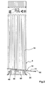
- zeigt schematisch einen Straßenbahnzug mit zwei Übergängen und zwei Drehgestellen;
Figur 2- zeigt eine Seitenansicht eines Übergangs zwischen zwei Fahrzeugen eines Straßenbauzuges, die durch ein Gelenk miteinander verbunden sind;
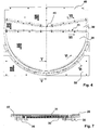
Figur 3- zeigt eine Ansicht von oben auf die Übergangsbrücke des Übergangs gemäß
Figur 2; Figur 4- zeigt die Drehscheibe mit dem elastischen Zwischenglied und den zu beiden Seiten angeordneten Kuppelplatten als Übergangsbrücke des Übergangs in einer Draufsicht;
Figur 5- zeigt einen Schnitt gemäß der Linie V - V aus
Figur 4; Figur 6- zeigt einen Schnitt gemäß der Linie VI - VI aus
Figur 4; - Figur 7
- zeigt einen Schnitt gemäß der Linie VII - VII aus
Figur 4.
- FIG. 1
- schematically shows a tram train with two transitions and two bogies;
- FIG. 2
- shows a side view of a transition between two vehicles of a road construction train, which are connected by a hinge with each other;
- FIG. 3
- shows a view from above of the transition bridge of the transition according to Figure 2;
- FIG. 4
- shows the hub with the elastic intermediate member and the dome plates arranged on both sides as a transition bridge of the transition in a plan view;
- FIG. 5
- shows a section along the line V - V of Figure 4;
- FIG. 6
- shows a section along the line VI - VI of Figure 4;
- FIG. 7
- shows a section along the line VII - VII of Figure 4.
Der mit 1 gekennzeichnete Straßenbahnzug umfasst die drei Fahrzeuge 2, 3 und 4, die durch die Übergänge 5 miteinander in Verbindung stehen. Im Bereich der Übergänge 5 weist der Schienengelenkzug die beiden Drehgestelle 6 auf. Fährt ein solches Fahrzeug beispielsweise um eine Kurve, dann folgt der Straßenbahnzug dem Kurvenverlauf durch Knicken im Bereich der Übergänge 5.The tram line marked 1 comprises the three
Gegenstand der Erfindung ist nun die Übergangsbrücke 10 als Teil des insgesamt mit 5 bezeichneten Übergangs (Fig. 2 ff). Die Übergangsbrücke 10, umfassend die Drehscheibe 20, das elastische Zwischenglied 30 und die Kuppelplatte 40 sowie die Kuppelplatte 50, befindet sich schräg verlaufend über dem mit 60 bezeichneten Gelenk zur Verbindung der beiden Fahrzeuge 3, wie sich dies aus Figur 2 ergibt. Umspannt wird die Übergangsbrücke sowie auch das Gelenk 60 durch den insgesamt mit 15 bezeichneten Balg, wie sich dies insbesondere in Anschauung der Figuren 2 und 3 ergibt. Insbesondere aus Figur 3 ist erkennbar, dass die Abschlusskante 21 der Drehscheibe 20 durch den Drehpunkt 61 des Gelenkes 60 verläuft. Die Kuppelplatte 40 ist in Richtung auf die Abschlusskante 21 zu pfeilförmig (Pfeil 45) ausgebildet, wobei die Spitze der pfeilförmigen Kuppelplatte zentrisch auf den Drehpunkt (61) des Gelenkes 60 zuweist. Das elastische Zwischenglied 30 folgt schlussendlich dem Verlauf sowohl der Drehscheibe in diesem Bereich als auch der Kuppelplatte 40. Eine solche Ausbildung des elastischen Zwischengliedes hat sich insofern als vorteilhaft herausgestellt, als durch diese Gestaltung im Mittenbereich dieses elastischen Zwischengliedes die geringsten Spannungen auftreten.The subject of the invention is now the
Betrachtet man nunmehr die Figur 5 als Schnitt der Linie V - V aus Figur 4, so erkennt man ebenso wie aus der Figur 6 die Einspannung der Drehscheibe 20 durch die Kuppelplatte 50. Im Einzelnen ist hierbei eine Spannleiste 25 vorgesehen, wobei die Spannleiste 25 durch kreisbogenförmig angeordnete Schrauben 26 mit der Kuppelplatte 50 verbunden ist. Zwischen der Spannleiste 25 und der Drehscheibe 20 einerseits und der Kuppelplatte andererseits befindet sich eine Gleitleiste 27, um eine Relativbewegung der Drehscheibe 20 zur Kuppelplatte 50 und damit schlussendlich zum Boden des damit gekuppelten Fahrzeugs zu gewährleisten.Looking now to Figure 5 as a section of the line V - V of Figure 4, it can be seen as well as from Figure 6, the clamping of the
Betrachtet man nunmehr den Schnitt gemäß der Figur 6 so erkennt man, dass dort die Kuppelplatte 50 mit der Konterleiste 55 durch Schrauben 56 verbunden ist. Auch hier befindet sich zwischen der Drehscheibe 20 und der Kuppelplatte 50 einerseits und der Konterleiste 55 andererseits eine Gleitleiste 57, um die Relativbewegung der Drehscheibe 20 einerseits zu der Konterleiste 55, die - wie bereits ausgeführt - mit der Kuppelplatte 50 durch die Schrauben 56 starr verbunden ist, zu gewährleisten. Erkennbar ist zwischen der Stirnseite 22, der Drehscheibe 20 und der Stirnseite 53 der Kuppelplatte 50 ein Spalt 70 erkennbar, wobei ein ebensolcher Spalt 75 auch im Bereich der Spannleiste 25, und hier insbesondere zwischen der Stirnkante der Gleitleiste 27 und einer Stufe 23 der Drehscheibe 20, vorgesehen ist, wobei die beiden Spalten dazu dienen, eine Nickbewegung der in dieser Weise verbundenen Fahrzeuge zu ermöglichen.If one now considers the section according to FIG. 6, it can be seen that the
Die Verbindung des elastischen Zwischengliedes 30 mit der Kuppelplatte 40 einerseits und der Drehscheibe 20 andererseits ist in Figur 7 dargestellt. Das elastische Zwischenglied 30, das aus einem Elastomer oder einem elastischen Kunststoff besteht, ist durch die Verbindungsleisten 35 jeweils mit der Kuppelplatte 60 und der Drehscheibe 20 verschraubt. Das elastische Zwischenglied 30 weist auf seiner Oberseite eine verschleißfeste Oberfläche 31 auf, die insbesondere durch die Auflage eines dünnen Bleches bewerkstelligt werden kann.The connection of the elastic
Claims (15)
durch ein Gelenk miteinander verbundenen Fahrzeugen (2, 3, 4),
dadurch gekennzeichnet,
dass die Drehscheibe (20) mit ihrem einen Ende durch ein elastisches Zwischenglied (30) mit dem Boden des einen Fahrzeugs (2, 3, 4) in Verbindung steht.Bridge (10) with turntable of a transition (5) between two
articulated vehicles (2, 3, 4),
characterized,
in that the turntable (20) is connected at one end to the bottom of the one vehicle (2, 3, 4) by an elastic intermediate member (30).
dadurch gekennzeichnet,
dass die Drehscheibe (20) über dem Gelenk (60) schräg stehend verläuft, wobei die schräg stehende Drehscheibe (20) an ihrem anderen Ende mit dem Fahrzeugboden des anderen Fahrzeugs (2, 3, 4) in Verbindung steht.Bridge according to claim 1,
characterized,
in that the turntable (20) extends obliquely above the joint (60), the inclined turntable (20) communicating at its other end with the vehicle floor of the other vehicle (2, 3, 4).
dadurch gekennzeichnet,
dass die Drehscheibe (20) im Übergang zum Boden des anderen Fahrzeugs eingespannt gehalten ist.Bridge according to one of the preceding claims,
characterized,
in that the turntable (20) is held clamped in the transition to the floor of the other vehicle.
dadurch gekennzeichnet,
dass die Drehscheibe (20) im Übergang zum Boden des anderen Fahrzeugs durch eine Kuppelplatte (50) eingespannt gehalten ist.Bridge according to one of the preceding claims,
characterized,
is held clamped to the turntable (20) in the transition to the floor of the other vehicle by a coupling plate (50).
dadurch gekennzeichnet,
dass die die Brücke (10) bildenden Teile (20, 30) parallel zur Längsachse des Fahrzeugs (2, 3, 4) verschieblich angeordnet sind.Bridge according to one of the preceding claims,
characterized,
in that the parts (20, 30) forming the bridge (10) are arranged displaceably parallel to the longitudinal axis of the vehicle (2, 3, 4).
dadurch gekennzeichnet,
dass die Drehscheibe (20) entlang ihres stirnseitigen Umfang relativ zum Boden des Fahrzeugs verschieblich eingespannt gehalten ist.Bridge according to one of the preceding claims,
characterized,
that the turntable (20) along its front side circumference is slidably held clamped relative to the floor of the vehicle.
dadurch gekennzeichnet,
dass zwischen der Stirnseite der Drehscheibe (20) und der Kuppelplatte ein umlaufender Spalt (70) vorgesehen ist, wobei zur eingespannten Halterung der Drehscheibe (20) eine Spannleiste (25) vorgesehen ist, die die Randbereiche der Drehscheibe (20) und der Kuppelplatte überdeckt, und die mit einer Konterleiste (55) unter der Drehscheibe (20) verbunden ist.Bridge according to one of the preceding claims,
characterized,
that a circumferential gap (70) is provided between the end face of the rotary disc (20) and the dome plate, wherein for clamped holding of the rotary disc (20) has a clamping bar (25) is provided, which covers the edge regions of the hub (20) and the dome plate , and which is connected to a counter ledge (55) under the turntable (20).
dadurch gekennzeichnet,
dass zwischen Spannleiste (20) einerseits und Drehscheibe (20) und Kuppelplatte (50) andererseits eine Gleitleiste (27) vorgesehen ist.Bridge according to one of the preceding claims,
characterized,
that between clamping bar (20) on the one hand and turntable (20) and dome plate (50) on the other hand, a slide strip (27) is provided.
dadurch gekennzeichnet,
dass zwischen Konterleiste (55) einerseits und Drehscheibe (20) und Kuppelplatte (50) andererseits eine Gleitleiste vorgesehen ist.Bridge according to one of the preceding claims,
characterized,
that between the counter ledge (55) on the one hand and turntable (20) and dome plate (50) on the other hand, a slide strip is provided.
dadurch gekennzeichnet,
dass das elastische Zwischenglied (30) als Platte ausgebildet ist.Bridge according to claim 1,
characterized,
that the elastic intermediate member (30) is formed as a plate.
dadurch gekennzeichnet,
dass das elastische Zwischenglied (30) durch Verbindungsleisten (35) mit jeweils dem Fahrzeugboden und der Drehscheibe (20) verbunden ist.Bridge according to claim 1,
characterized,
that the elastic intermediate member (30) by connecting strips (35) is connected to each of the vehicle floor and the turntable (20).
dadurch gekennzeichnet,
dass die Drehscheibe (20) im Übergang zum Fahrzeugboden des einen Fahrzeugs kreisbogenförmig ausgebildet ist.Bridge according to one of the preceding claims,
characterized,
that the turntable (20) is formed in a circular arc in the transition to the vehicle floor of a vehicle.
dadurch gekennzeichnet,
dass die Abschlusskante (21) der Drehscheibe (20) im Übergang zum elastischen Zwischenglied (30) durch den Drehpunkt (61) des Gelenkes (60) verläuft.Bridge according to one of the preceding claims,
characterized,
in that the end edge (21) of the turntable (20) extends in the transition to the elastic intermediate member (30) through the pivot point (61) of the joint (60).
dadurch gekennzeichnet,
dass der Boden des anderen Fahrzeugs im Übergang zum elastischen Zwischenglied pfeilförmig (45) verlaufend ausgebildet ist, wobei das elastische Zwischenglied (30) korrespondierend hierzu verläuft.Bridge according to one of the preceding claims,
characterized,
that the bottom of the other vehicle in the transition to the elastic intermediate member arrow-shaped (45) extending, wherein the elastic intermediate member (30) corresponding thereto extends.
dadurch gekennzeichnet,
dass der Boden des einen Fahrzeugs im Übergang zu dem elastischen Zwischenglied (30) eine Kuppelplatte (40) aufweist.Bridge according to claim 1,
characterized,
in that the bottom of the one vehicle has a dome plate (40) in transition to the elastic intermediate member (30).
Priority Applications (1)
| Application Number | Priority Date | Filing Date | Title |
|---|---|---|---|
| PL07009125T PL1854691T5 (en) | 2006-05-09 | 2007-05-07 | Bridge with turntable for the intersection of two vehicles with a jointed connection |
Applications Claiming Priority (1)
| Application Number | Priority Date | Filing Date | Title |
|---|---|---|---|
| DE202006007377U DE202006007377U1 (en) | 2006-05-09 | 2006-05-09 | Bridge with turntable for creation of articulated bus or tram, comprising turntable arranged in inclined position above movable joint |
Publications (3)
| Publication Number | Publication Date |
|---|---|
| EP1854691A1 true EP1854691A1 (en) | 2007-11-14 |
| EP1854691B1 EP1854691B1 (en) | 2009-06-24 |
| EP1854691B2 EP1854691B2 (en) | 2013-04-03 |
Family
ID=36776761
Family Applications (1)
| Application Number | Title | Priority Date | Filing Date |
|---|---|---|---|
| EP07009125A Active EP1854691B2 (en) | 2006-05-09 | 2007-05-07 | Bridge with turntable for the intersection of two vehicles with a jointed connection |
Country Status (5)
| Country | Link |
|---|---|
| EP (1) | EP1854691B2 (en) |
| AT (1) | ATE434552T1 (en) |
| DE (2) | DE202006007377U1 (en) |
| ES (1) | ES2327006T5 (en) |
| PL (1) | PL1854691T5 (en) |
Cited By (6)
| Publication number | Priority date | Publication date | Assignee | Title |
|---|---|---|---|---|
| EP2394877A1 (en) | 2010-06-09 | 2011-12-14 | ATG Autotechnik GmbH | Bridging platform for a vehicle joint |
| EP2447129A1 (en) | 2010-11-02 | 2012-05-02 | Bombardier Transportation GmbH | Connecting element for floor elements of vehicles |
| DE102010050005A1 (en) | 2010-11-02 | 2012-05-03 | Bombardier Transportation Gmbh | Connector for connecting e.g. bridge plate and base plate of rail vehicle, has lips for covering upper-sides of edge areas of elements, where connector comprises material provided in region of recess and in other regions of another material |
| WO2012101201A1 (en) | 2011-01-28 | 2012-08-02 | Bombardier Transportation Gmbh | Rail vehicle bridge |
| DE102013218547B3 (en) * | 2013-09-16 | 2015-02-05 | Bombardier Transportation Gmbh | Transitional platform with torsion zones, vehicle hinge system and rail vehicle |
| EP3124294A1 (en) * | 2015-07-30 | 2017-02-01 | Siemens Aktiengesellschaft | Covering device for covering a floor gap, as well as a vehicle having such a covering device |
Families Citing this family (4)
| Publication number | Priority date | Publication date | Assignee | Title |
|---|---|---|---|---|
| PL2384914T3 (en) * | 2010-05-03 | 2013-01-31 | Huebner Gmbh & Co Kg | Articulated vehicle, in particular rail vehicle |
| EP2412600B1 (en) * | 2010-07-29 | 2012-09-05 | ATG Autotechnik GmbH | Roof joint for an articulated vehicle |
| PL2441601T3 (en) * | 2010-10-14 | 2013-09-30 | Huebner Gmbh | Turntable for the intersection of two vehicles with a jointed connection |
| EP4385849A1 (en) * | 2022-12-14 | 2024-06-19 | Hübner GmbH & Co. KG | Guide device for a transition between a first vehicle part and a second vehicle part of a multi-part vehicle, and vehicle having such a guide device |
Citations (4)
| Publication number | Priority date | Publication date | Assignee | Title |
|---|---|---|---|---|
| FR2581016A1 (en) * | 1985-04-25 | 1986-10-31 | Alsthom Atlantique | Connecting device between two rail vehicles |
| FR2581011A1 (en) | 1985-04-25 | 1986-10-31 | Reidenbach Roger | Checking bench for braking installations and for all the connection pieces and articulations between the chassis and the wheels of a motor vehicle |
| DE4138921A1 (en) | 1991-11-27 | 1993-06-03 | Huebner Gummi & Kunststoff | Disc shaped platform between two parts of omnibus - has shelf support which is elastically deformable in vertical direction |
| DE9413285U1 (en) | 1994-08-17 | 1995-06-08 | Aeg Schienenfahrzeuge Gmbh, 16761 Hennigsdorf | Turntable for the crossing of rail vehicles |
-
2006
- 2006-05-09 DE DE202006007377U patent/DE202006007377U1/en not_active Expired - Lifetime
-
2007
- 2007-05-07 AT AT07009125T patent/ATE434552T1/en active
- 2007-05-07 ES ES07009125T patent/ES2327006T5/en active Active
- 2007-05-07 PL PL07009125T patent/PL1854691T5/en unknown
- 2007-05-07 DE DE502007000918T patent/DE502007000918D1/en active Active
- 2007-05-07 EP EP07009125A patent/EP1854691B2/en active Active
Patent Citations (4)
| Publication number | Priority date | Publication date | Assignee | Title |
|---|---|---|---|---|
| FR2581016A1 (en) * | 1985-04-25 | 1986-10-31 | Alsthom Atlantique | Connecting device between two rail vehicles |
| FR2581011A1 (en) | 1985-04-25 | 1986-10-31 | Reidenbach Roger | Checking bench for braking installations and for all the connection pieces and articulations between the chassis and the wheels of a motor vehicle |
| DE4138921A1 (en) | 1991-11-27 | 1993-06-03 | Huebner Gummi & Kunststoff | Disc shaped platform between two parts of omnibus - has shelf support which is elastically deformable in vertical direction |
| DE9413285U1 (en) | 1994-08-17 | 1995-06-08 | Aeg Schienenfahrzeuge Gmbh, 16761 Hennigsdorf | Turntable for the crossing of rail vehicles |
Cited By (8)
| Publication number | Priority date | Publication date | Assignee | Title |
|---|---|---|---|---|
| EP2394877A1 (en) | 2010-06-09 | 2011-12-14 | ATG Autotechnik GmbH | Bridging platform for a vehicle joint |
| EP2447129A1 (en) | 2010-11-02 | 2012-05-02 | Bombardier Transportation GmbH | Connecting element for floor elements of vehicles |
| DE102010050005A1 (en) | 2010-11-02 | 2012-05-03 | Bombardier Transportation Gmbh | Connector for connecting e.g. bridge plate and base plate of rail vehicle, has lips for covering upper-sides of edge areas of elements, where connector comprises material provided in region of recess and in other regions of another material |
| DE102010050005B4 (en) * | 2010-11-02 | 2014-06-05 | Bombardier Transportation Gmbh | Connecting element for floor elements of vehicles |
| WO2012101201A1 (en) | 2011-01-28 | 2012-08-02 | Bombardier Transportation Gmbh | Rail vehicle bridge |
| DE102011009767A1 (en) | 2011-01-28 | 2012-08-02 | Bombardier Transportation Gmbh | Rail car bridge |
| DE102013218547B3 (en) * | 2013-09-16 | 2015-02-05 | Bombardier Transportation Gmbh | Transitional platform with torsion zones, vehicle hinge system and rail vehicle |
| EP3124294A1 (en) * | 2015-07-30 | 2017-02-01 | Siemens Aktiengesellschaft | Covering device for covering a floor gap, as well as a vehicle having such a covering device |
Also Published As
| Publication number | Publication date |
|---|---|
| EP1854691B1 (en) | 2009-06-24 |
| EP1854691B2 (en) | 2013-04-03 |
| PL1854691T3 (en) | 2009-10-30 |
| ES2327006T3 (en) | 2009-10-22 |
| PL1854691T5 (en) | 2013-08-30 |
| DE202006007377U1 (en) | 2006-07-20 |
| DE502007000918D1 (en) | 2009-08-06 |
| ES2327006T5 (en) | 2013-05-27 |
| ATE434552T1 (en) | 2009-07-15 |
Similar Documents
| Publication | Publication Date | Title |
|---|---|---|
| EP1854691B2 (en) | Bridge with turntable for the intersection of two vehicles with a jointed connection | |
| EP2500230B1 (en) | Bridge for the intersection of two vehicle sections with a jointed connection | |
| EP1574365B1 (en) | Communication passage with a gangway footplate between articulated vehicles | |
| EP0283808B1 (en) | Dual switching system for simultaneous use by rail and magnetic vehicles | |
| EP2019880A1 (en) | Junction for guideways of vehicles, in particular of magnetic levitation railways | |
| EP2455242A1 (en) | Assembly for forming the bellows of a transition or the side wall between two vehicles with a jointed connection | |
| DE202013100563U1 (en) | Bridge between two articulated vehicle parts | |
| EP0731763B1 (en) | Inner lining for gangways between rail vehicles | |
| EP2594450B1 (en) | Intersection half between two loose jointed vehicles of a rail car | |
| WO2012101201A1 (en) | Rail vehicle bridge | |
| EP1526055A1 (en) | Railway vehicle, in particular a tramway vehicle, with an elastically mounted floor in the cabin. | |
| DE69402109T2 (en) | Twistable plate for transition facilities | |
| DE102010050005A1 (en) | Connector for connecting e.g. bridge plate and base plate of rail vehicle, has lips for covering upper-sides of edge areas of elements, where connector comprises material provided in region of recess and in other regions of another material | |
| EP2441601B1 (en) | Turntable for the intersection of two vehicles with a jointed connection | |
| DE102017115542A1 (en) | Railway vehicle association and wagon for a rail vehicle association | |
| DE10061380B4 (en) | Wheel with a wheel flange for a rail-bound vehicle | |
| DE29707031U1 (en) | Articulated vehicle | |
| EP2974937B1 (en) | Connection between two articulated vehicles | |
| EP4385849A1 (en) | Guide device for a transition between a first vehicle part and a second vehicle part of a multi-part vehicle, and vehicle having such a guide device | |
| DE202008005243U1 (en) | Park for motor vehicles | |
| EP2447129B1 (en) | Connecting element for floor elements of vehicles | |
| EP4035911A1 (en) | Bridge for a transition between two vehicle sections with a jointed connection | |
| CH621832A5 (en) | Railway sleeper | |
| DE2350759C3 (en) | Level crossing with two deck slabs between the rails of a track | |
| DE1478456A1 (en) | Large building body for toy building systems |
Legal Events
| Date | Code | Title | Description |
|---|---|---|---|
| PUAI | Public reference made under article 153(3) epc to a published international application that has entered the european phase |
Free format text: ORIGINAL CODE: 0009012 |
|
| 17P | Request for examination filed |
Effective date: 20070924 |
|
| AK | Designated contracting states |
Kind code of ref document: A1 Designated state(s): AT BE BG CH CY CZ DE DK EE ES FI FR GB GR HU IE IS IT LI LT LU LV MC MT NL PL PT RO SE SI SK TR |
|
| AX | Request for extension of the european patent |
Extension state: AL BA HR MK YU |
|
| 17Q | First examination report despatched |
Effective date: 20071227 |
|
| AKX | Designation fees paid |
Designated state(s): AT DE ES FR IT PL |
|
| GRAP | Despatch of communication of intention to grant a patent |
Free format text: ORIGINAL CODE: EPIDOSNIGR1 |
|
| GRAS | Grant fee paid |
Free format text: ORIGINAL CODE: EPIDOSNIGR3 |
|
| GRAA | (expected) grant |
Free format text: ORIGINAL CODE: 0009210 |
|
| AK | Designated contracting states |
Kind code of ref document: B1 Designated state(s): AT DE ES FR IT PL |
|
| REF | Corresponds to: |
Ref document number: 502007000918 Country of ref document: DE Date of ref document: 20090806 Kind code of ref document: P |
|
| REG | Reference to a national code |
Ref country code: ES Ref legal event code: FG2A Ref document number: 2327006 Country of ref document: ES Kind code of ref document: T3 |
|
| REG | Reference to a national code |
Ref country code: PL Ref legal event code: T3 |
|
| PLBI | Opposition filed |
Free format text: ORIGINAL CODE: 0009260 |
|
| PLAB | Opposition data, opponent's data or that of the opponent's representative modified |
Free format text: ORIGINAL CODE: 0009299OPPO |
|
| PLAX | Notice of opposition and request to file observation + time limit sent |
Free format text: ORIGINAL CODE: EPIDOSNOBS2 |
|
| 26 | Opposition filed |
Opponent name: BOMBARDIER TRANSPORTATION GMBH Effective date: 20100324 |
|
| R26 | Opposition filed (corrected) |
Opponent name: BOMBARDIER TRANSPORTATION GMBH Effective date: 20100324 |
|
| PLAF | Information modified related to communication of a notice of opposition and request to file observations + time limit |
Free format text: ORIGINAL CODE: EPIDOSCOBS2 |
|
| PLBB | Reply of patent proprietor to notice(s) of opposition received |
Free format text: ORIGINAL CODE: EPIDOSNOBS3 |
|
| PG25 | Lapsed in a contracting state [announced via postgrant information from national office to epo] |
Ref country code: IT Free format text: LAPSE BECAUSE OF NON-PAYMENT OF DUE FEES Effective date: 20100507 |
|
| PLBP | Opposition withdrawn |
Free format text: ORIGINAL CODE: 0009264 |
|
| PLAY | Examination report in opposition despatched + time limit |
Free format text: ORIGINAL CODE: EPIDOSNORE2 |
|
| PLBC | Reply to examination report in opposition received |
Free format text: ORIGINAL CODE: EPIDOSNORE3 |
|
| PUAH | Patent maintained in amended form |
Free format text: ORIGINAL CODE: 0009272 |
|
| STAA | Information on the status of an ep patent application or granted ep patent |
Free format text: STATUS: PATENT MAINTAINED AS AMENDED |
|
| 27A | Patent maintained in amended form |
Effective date: 20130403 |
|
| AK | Designated contracting states |
Kind code of ref document: B2 Designated state(s): AT DE ES FR IT PL |
|
| REG | Reference to a national code |
Ref country code: ES Ref legal event code: DC2A Ref document number: 2327006 Country of ref document: ES Kind code of ref document: T5 Effective date: 20130527 |
|
| REG | Reference to a national code |
Ref country code: DE Ref legal event code: R102 Ref document number: 502007000918 Country of ref document: DE Effective date: 20130403 |
|
| REG | Reference to a national code |
Ref country code: PL Ref legal event code: T5 |
|
| REG | Reference to a national code |
Ref country code: FR Ref legal event code: PLFP Year of fee payment: 10 |
|
| REG | Reference to a national code |
Ref country code: FR Ref legal event code: PLFP Year of fee payment: 11 |
|
| REG | Reference to a national code |
Ref country code: FR Ref legal event code: PLFP Year of fee payment: 12 |
|
| REG | Reference to a national code |
Ref country code: DE Ref legal event code: R082 Ref document number: 502007000918 Country of ref document: DE Representative=s name: WALTHER HINZ BAYER PARTG MBB PATENTANWAELTE, DE Ref country code: DE Ref legal event code: R081 Ref document number: 502007000918 Country of ref document: DE Owner name: HUEBNER GMBH & CO. KG, DE Free format text: FORMER OWNER: HUEBNER GMBH, 34123 KASSEL, DE Ref country code: DE Ref legal event code: R082 Ref document number: 502007000918 Country of ref document: DE Representative=s name: WALTHER HINZ BAYER PARTGMBB PATENTANWAELTE, DE |
|
| PGFP | Annual fee paid to national office [announced via postgrant information from national office to epo] |
Ref country code: FR Payment date: 20200519 Year of fee payment: 14 Ref country code: ES Payment date: 20200618 Year of fee payment: 14 |
|
| PGFP | Annual fee paid to national office [announced via postgrant information from national office to epo] |
Ref country code: IT Payment date: 20200528 Year of fee payment: 14 |
|
| PG25 | Lapsed in a contracting state [announced via postgrant information from national office to epo] |
Ref country code: FR Free format text: LAPSE BECAUSE OF NON-PAYMENT OF DUE FEES Effective date: 20210531 |
|
| REG | Reference to a national code |
Ref country code: ES Ref legal event code: FD2A Effective date: 20220729 |
|
| PG25 | Lapsed in a contracting state [announced via postgrant information from national office to epo] |
Ref country code: ES Free format text: LAPSE BECAUSE OF NON-PAYMENT OF DUE FEES Effective date: 20210508 |
|
| PG25 | Lapsed in a contracting state [announced via postgrant information from national office to epo] |
Ref country code: IT Free format text: LAPSE BECAUSE OF NON-PAYMENT OF DUE FEES Effective date: 20210531 |
|
| P01 | Opt-out of the competence of the unified patent court (upc) registered |
Effective date: 20230911 |
|
| PGFP | Annual fee paid to national office [announced via postgrant information from national office to epo] |
Ref country code: DE Payment date: 20240517 Year of fee payment: 18 |
|
| PGFP | Annual fee paid to national office [announced via postgrant information from national office to epo] |
Ref country code: AT Payment date: 20240517 Year of fee payment: 18 |
|
| PGFP | Annual fee paid to national office [announced via postgrant information from national office to epo] |
Ref country code: PL Payment date: 20240426 Year of fee payment: 18 |