EP1854669A2 - Aussenspiegel für ein Kraftfahrzeug - Google Patents
Aussenspiegel für ein Kraftfahrzeug Download PDFInfo
- Publication number
- EP1854669A2 EP1854669A2 EP07009287A EP07009287A EP1854669A2 EP 1854669 A2 EP1854669 A2 EP 1854669A2 EP 07009287 A EP07009287 A EP 07009287A EP 07009287 A EP07009287 A EP 07009287A EP 1854669 A2 EP1854669 A2 EP 1854669A2
- Authority
- EP
- European Patent Office
- Prior art keywords
- mirror
- insert
- holder
- exterior mirror
- housing
- Prior art date
- Legal status (The legal status is an assumption and is not a legal conclusion. Google has not performed a legal analysis and makes no representation as to the accuracy of the status listed.)
- Granted
Links
- 238000004519 manufacturing process Methods 0.000 claims abstract description 8
- 239000003365 glass fiber Substances 0.000 claims abstract description 5
- 239000011152 fibreglass Substances 0.000 claims abstract description 3
- 238000000034 method Methods 0.000 claims abstract description 3
- 238000001746 injection moulding Methods 0.000 claims description 20
- 239000004033 plastic Substances 0.000 claims description 7
- 229920003023 plastic Polymers 0.000 claims description 7
- 239000002991 molded plastic Substances 0.000 claims description 3
- 238000013461 design Methods 0.000 description 10
- 230000007704 transition Effects 0.000 description 7
- 238000002347 injection Methods 0.000 description 3
- 239000007924 injection Substances 0.000 description 3
- 238000000465 moulding Methods 0.000 description 3
- 238000012549 training Methods 0.000 description 3
- 238000011109 contamination Methods 0.000 description 2
- 230000001419 dependent effect Effects 0.000 description 2
- 239000011521 glass Substances 0.000 description 2
- 239000000463 material Substances 0.000 description 2
- 238000005259 measurement Methods 0.000 description 2
- 230000006866 deterioration Effects 0.000 description 1
- 238000011161 development Methods 0.000 description 1
- 230000018109 developmental process Effects 0.000 description 1
- 230000000694 effects Effects 0.000 description 1
- 238000002474 experimental method Methods 0.000 description 1
- 230000002349 favourable effect Effects 0.000 description 1
- 239000011888 foil Substances 0.000 description 1
- 238000010438 heat treatment Methods 0.000 description 1
- 230000002787 reinforcement Effects 0.000 description 1
- 239000000243 solution Substances 0.000 description 1
- XLYOFNOQVPJJNP-UHFFFAOYSA-N water Substances O XLYOFNOQVPJJNP-UHFFFAOYSA-N 0.000 description 1
- 238000003466 welding Methods 0.000 description 1
Images


Classifications
-
- B—PERFORMING OPERATIONS; TRANSPORTING
- B60—VEHICLES IN GENERAL
- B60R—VEHICLES, VEHICLE FITTINGS, OR VEHICLE PARTS, NOT OTHERWISE PROVIDED FOR
- B60R1/00—Optical viewing arrangements; Real-time viewing arrangements for drivers or passengers using optical image capturing systems, e.g. cameras or video systems specially adapted for use in or on vehicles
- B60R1/02—Rear-view mirror arrangements
- B60R1/06—Rear-view mirror arrangements mounted on vehicle exterior
-
- B—PERFORMING OPERATIONS; TRANSPORTING
- B29—WORKING OF PLASTICS; WORKING OF SUBSTANCES IN A PLASTIC STATE IN GENERAL
- B29C—SHAPING OR JOINING OF PLASTICS; SHAPING OF MATERIAL IN A PLASTIC STATE, NOT OTHERWISE PROVIDED FOR; AFTER-TREATMENT OF THE SHAPED PRODUCTS, e.g. REPAIRING
- B29C45/00—Injection moulding, i.e. forcing the required volume of moulding material through a nozzle into a closed mould; Apparatus therefor
- B29C45/14—Injection moulding, i.e. forcing the required volume of moulding material through a nozzle into a closed mould; Apparatus therefor incorporating preformed parts or layers, e.g. injection moulding around inserts or for coating articles
-
- B—PERFORMING OPERATIONS; TRANSPORTING
- B29—WORKING OF PLASTICS; WORKING OF SUBSTANCES IN A PLASTIC STATE IN GENERAL
- B29L—INDEXING SCHEME ASSOCIATED WITH SUBCLASS B29C, RELATING TO PARTICULAR ARTICLES
- B29L2011/00—Optical elements, e.g. lenses, prisms
- B29L2011/0058—Mirrors
-
- B—PERFORMING OPERATIONS; TRANSPORTING
- B29—WORKING OF PLASTICS; WORKING OF SUBSTANCES IN A PLASTIC STATE IN GENERAL
- B29L—INDEXING SCHEME ASSOCIATED WITH SUBCLASS B29C, RELATING TO PARTICULAR ARTICLES
- B29L2031/00—Other particular articles
- B29L2031/30—Vehicles, e.g. ships or aircraft, or body parts thereof
Definitions
- the invention relates to an exterior mirror for a motor vehicle, for example for a passenger vehicle.
- Exterior mirror and bracket are often designed in two parts and should meet the aesthetic requirements of the customer to a high degree.
- a first aspect of the invention relates to an exterior mirror.
- a first embodiment thereof comprises a mirror housing with an associated V-, U- or L-shaped holder, wherein mirror housing and holder are integrally formed.
- transition areas Due to the one-piece design dividing lines, flanges, welding points, etc., hereinafter called transition areas, which would otherwise be present in a two-part training, avoided. In this way, the aforementioned technical transition areas between the holder and mirror housing are not available and must be made less compromise in the technical implementation of the design. In this respect, the training mentioned extends the design options in the implementation of an exterior mirror design into a concrete product. Furthermore, it comes because of the avoidance of the above-mentioned transition areas to less wind noise while driving and eliminates the one-piece or one-piece design of the exterior mirror mounting step, which consists of connecting bracket and mirror housing.
- An embodiment further provides that the mirror housing and the holder are injection-molded plastic parts, so that a unit of holder and mirror housing is produced by way of injection molding.
- the holder may be chosen so that they two opening into a mounting flange struts has. Between the two struts and the mirror housing is then a free space. Experiments in the wind tunnel have shown that this design of the holder with mirror housing shows a favorable noise behavior at the same time harmonious transitions and pleasing proportions.
- the holder has a plastic-coated V-, U- or L-shaped insert.
- a permanently remaining in the holder insert with injection-molded plastic manages to provide a V-, U- or L-shaped bracket.
- the insert stabilizes the holder mechanically and allows the possibility to attach the outside mirror to the body via the insert.
- the insert consists of glass fiber reinforced plastic.
- an insert is created, which is sufficiently thermally stable on the one hand in the production, and so far not deformed in the prevailing during injection molding temperatures, for example, 200 ° C to 230 ° C.
- the insert is sufficiently stiff to withstand the injection pressure or closing pressure of, for example, 600 bar to 1000 bar exerted during injection molding without being able to withstand its internal structure.
- a connection of the mirror housing with the Vehicle body for example via an electrical cable, with a recordable in the mirror housing actuator for the tilt adjustment of the mirror is switchable.
- the temperature stability and the stability can be adjusted to the injection pressure of the injection molding process to a great extent.
- Suitable values of the glass fiber content are, for example, 40% to 60% by weight and for example 50% by weight.
- Another aspect of the invention relates to a method of manufacturing an exterior mirror for a motor vehicle.
- the method comprises the steps of providing a V-U or L-shaped insert and spatially fixing the insert in a mold of an injection molding machine.
- a wrapping of the insert takes place with a plastic by injection molding, whereby an exterior mirror with mirror housing and holder is formed, are integrally formed in the mirror housing and holder.
- the provision of the insert may include its manufacture.
- the insert may be formed in two parts and comprises at least one cavity, for example in the form of a cable duct, for producing a connection, for example an electrical connection, from the body to the inner region of the mirror housing.
- the insert is in this case sufficiently stable to withstand the wind of a motor vehicle, which for example by Training of stiffening ribs can be realized.
- the struts may open into a mounting flange.
- the insert can also extend into the mounting flange in order to stabilize this mechanically.
- the mounting flange accommodates attachment means for mechanically connecting the outside mirror to the vehicle body, e.g. the outer door skin, on.
- a hinge or clips can be selected for a clip connection.
- the aforementioned manufacturing method allows the detailed reproduction of an exterior mirror design by an injection-molded exterior mirror without the above transition areas and thus with less compromise in the technical implementation.
- the use of an insert also creates the potential to produce an exterior mirror that is a V, U or L shaped Holder with two V, U or L forming web-shaped sections.
- Another aspect of the invention relates to a motor vehicle, such as a car, with an exterior mirror as described above.
- Figure 1 shows an exterior mirror 1 with a view from the front, i. with a view of the (not yet inserted) mirror surface. It can be seen a one-piece design of comprising a V-shaped bracket 2 and a mirror housing 3 outside mirror 1.
- the V-shape creates harmonious transitions and pleasing proportions housing without disturbing dividing lines, for example dividing lines in the transition region of the holder 2 and mirror housing 3.
- a mounting step for the mechanical connection of these two parts is saved. At the same time a deterioration of the noise behavior is avoided by said dividing lines.
- the V-shaped bracket 2 consists of two approximately finger-thick struts 4, which open into a mounting flange 5.
- the outside mirror 1 is attached to the body.
- the mounting flange 5 has suitable fastening means, for example via clips for a clip connection or via a hinge. If the outside mirror 1 is fastened to the outer door skin, a reinforcement can be provided under the door outer skin in order to improve the mechanical connection.
- Insert 6 Inside the injection-molded outside mirror 1, in the holder 2, there is a Insert 6.
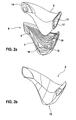
- the insert 6 is shown in Figures 2a and 2b.
- the insert 6 is, compare Figure 2a, formed in two parts and consists of base part 7 and upper part 8, which are fixed relative to each other via not shown tabs and then enclose a cavity.
- FIG. 2b shows the insert part 6 assembled from base part 7 and upper part 8, as used in the injection molding process.
- the base part 7 has inside ribs 9, which ensures the required mechanical stability. At the same time, it is ensured by the stiffening ribs 9 that the insert 6 is not mechanically deformed by the injection pressure during the injection molding process of the outside mirror 1 or that the above-mentioned cavity for the cable bushing breaks in.
- the Spritznachtik minimized with the sink marks on the outside of the outside mirror 1, is dependent on the plastic material and can be about 600 bar to about 800 bar.
- openings 10 serve to record clip bolts a Klipsbefest Trent.
- the region of the openings 10 extends into the mounting flange 5 in this respect.
- the insert 6 is made of plastic PBT with a glass fiber content of 50% by weight. It has a cable channel 11 for the electrical contacting of an im Mirror housing 2 accommodatable adjustment mechanism and holes for draining occurred water (not shown).
- the insert does not have any undercuts, so even with the injection molding machine it has a simple tool movable along a line, i. can be inexpensively manufactured with an on / off tool, without the use of a slider with a high clock rate.
- the mirror housing 3 and also the mirror provided therein, has in a view perpendicular to the mirror surface in approximately the shape of a lying, pointed sugarloaf. It shows when mounted on the outer door skin, inside a largely rectilinear boundary in the form of a baseline 19. To the outside it has a tip 20. The mirror surface is thus approximately triangular. In wind tunnel measurements confirmed for the outside mirror 1 with this mirror housing 3 a good aerodynamic behavior. At the same time, it turned out that the selected shape of the outside mirror produced air turbulence, which keeps contamination of the front door window low.
- FIG. 3 shows a (molding) tool 12 of an injection molding machine for producing the outside mirror 1.
- the tool 12 has two slides 13 and 14 for fixing the insert 6.
- the slider 13 acts on a first flange surface 15 of the insert 6, which with reference 2b on the bottom of the insert 6 is located.
- the slider 14 supports the flange surfaces 16 and 17. With the aid of the central receptacle 18, the insert enters the tool 12.
- the insert 6 is first provided. For this purpose, it can be produced even via an injection molding process. As material for the insert 6 PBT can be selected.
- the provided insert 6 is then fixed in the tool 12 by means of the slide 13, 14. Then the counter-forming tool moves in (-z) -direction to the tool 12 and the insert 6 is covered with a plastic.
- a holding pressure between 600 bar and 800 bar can be selected.
- FIG. 4 shows a motor vehicle 21 with an exterior mirror 1 in a wind tunnel, which with its fastening flange 5 on the outer skin of the front door 22 is attached. Air flows through a nozzle 23 in the form of an air stream 24 against the outside mirror 1.
- the wind tunnel measurements prove a good aerodynamic behavior and a good noise behavior without whistling and the like.
- the air flow behind the outside mirror 1 showed air turbulence, which keeps contamination of the front door window pane 25 low.
Landscapes
- Engineering & Computer Science (AREA)
- Mechanical Engineering (AREA)
- Manufacturing & Machinery (AREA)
- Multimedia (AREA)
- Rear-View Mirror Devices That Are Mounted On The Exterior Of The Vehicle (AREA)
- Injection Moulding Of Plastics Or The Like (AREA)
Abstract
Description
- Die Erfindung betrifft einen Außenspiegel für ein Kraftfahrzeug, zum Beispiel für ein Personenkraftfahrzeug.
- Außenspiegel an einem Kraftfahrzeug verfügen über eine Halterung, mit der sie an der Karosserie befestigt werden und die das Spiegelgehäuse trägt. Außenspiegel und Halterung sind vielfach zweiteilig ausgebildet und sollen in hohem Maße den ästhetischen Ansprüchen des Kunden genügen.
- Es ist eine Aufgabe einer Ausführungsform der Erfindung, einen Außenspiegel und ein korrespondierendes Herstellungsverfahren bereitzustellen, mit dem ein vorgegebenes Design möglichst unverfälscht technisch realisiert werden kann.
- Die Lösung dieser Aufgabe erfolgt mit den Merkmalen der unabhängigen Ansprüche. Vorteilhafte Weiterbildungen werden durch die Merkmale der abhängigen Ansprüche wiedergegeben.
- Ein erster Aspekt der Erfindung bezieht sich auf einen Außenspiegel. Eine erste Ausführungsform desselben umfasst ein Spiegelgehäuse mit einer zugeordneten V-, U- oder L-förmigen Halterung, wobei Spiegelgehäuse und Halterung einstückig ausgebildet sind.
- Durch die einstückige Ausbildung werden Trennlinien, Flansche, Verschweißungsstellen etc., nachfolgend Übergangsbereiche genannt, die ansonsten bei einer zweiteiligen Ausbildung vorlägen, vermieden. Auf diese Weise kommen die genannten technisch bedingten Übergangsbereiche zwischen Halterung und Spiegelgehäuse nicht vor und müssen weniger Kompromisse bei der technischen Umsetzung des Designs eingegangen werden. Insofern erweitert die genannte Ausbildung die Gestaltungsmöglichkeiten bei der Umsetzung eines Außenspiegeldesigns in ein konkretes Produkt. Weiterhin kommt es wegen der Vermeidung der oben genannten Übergangsbereiche zu weniger Windgeräuschen im Fahrbetrieb und entfällt durch die einstückige bzw. einteilige Ausbildung des Außenspiegels ein Montageschritt, der im Verbinden von Halterung und Spiegelgehäuse besteht.
- Eine Ausführungsform sieht ferner vor, dass Spiegelgehäuse und Halterung spritzgegossene Kunststoffteile sind, sodass im Wege des Spritzgießens eine Einheit aus Halterung und Spiegelgehäuse hergestellt wird.
- Die Halterung kann so gewählt sein, dass sie zwei in einen Befestigungsflansch mündende Streben besitzt. Zwischen den beiden Streben und dem Spiegelgehäuse ist dann ein freier Zwischenraum. Experimente im Windkanal haben ergeben, dass diese Ausbildung der Halterung mit Spiegelgehäuse ein günstiges Geräuschverhalten bei gleichzeitig harmonischen Übergängen und gefälligen Proportionen zeigt.
- In einer Ausgestaltung besitzt die Halterung ein kunststoffumspritztes V-, U- oder L-förmiges Einlegeteil. Durch die Ummantelung eines dauerhaft in der Halterung verbleibenden Einlegeteils mit spritzgegossenem Kunststoff gelingt die Bereitstellung einer V-, U- oder L-förmigen Halterung. Bei einem direkten Spritzgießen ohne Einlegeteil bestünde ansonsten das Problem, wie ein Abformen der zusammenlaufenden Streben in der Spritzgießmaschine zu gewährleisten wäre. Das Einlegeteil stabilisiert die Halterung mechanisch und erlaubt bietet die Möglichkeit, den Außenspiegel über das Einlegeteil an der Karosserie zu befestigen.
- In einer weiteren Ausführungsform besteht das Einlegeteil aus glasfaserverstärktem Kunststoff. Durch diese Wahl wird ein Einlegeteil geschaffen, das zum einen in der Herstellung hinreichend thermisch stabil ist, und sich insofern bei den beim Spritzgießen vorherrschenden Temperaturen von zum Beispiel 200 °C bis 230 °C nicht verformt. Andererseits ist das Einlegeteil hinreichend steif, um den beim Spritzgießen ausgeübten Spritznach- bzw. Schließdruck von zum Beispiel 600 bar bis 1000 bar standzuhalten, ohne dass seine Innenstruktur einbricht standzuhalten. Durch die genannte Innenstruktur erfolgt eine Verbindung des Spiegelgehäuses mit der Fahrzeugkarosserie, zum Beispiel über ein elektrisches Kabel, mit dem ein im Spiegelgehäuse aufnehmbarer Aktuator für die Neigungsverstellung des Spiegels schaltbar ist.
- Durch eine geeignete Wahl des Glasfaseranteils können die Temperaturstabilität und die Stabilität gegenüber dem Spritznachdruck des Spritzgießprozesses in weitem Maße eingestellt werden. Geeignete Werte des Glasfaseranteils sind zum Beispiel 40 Gewichtsprozent bis 60 Gewichtsprozent und zum Beispiel 50 Gewichtsprozent.
- Ein weiterer Aspekt der Erfindung bezieht sich auf ein Verfahren zur Herstellung eines Außenspiegels für ein Kraftfahrzeug. Das Verfahren umfasst die Schritte Bereitstellen eines V- U- oder L-förmigen Einlegeteils und räumliches Fixieren des Einlegeteils in einem Werkzeug einer Spritzgießmaschine. In einem weiteren Schritt erfolgt ein Ummanteln des Einlegeteils mit einem Kunststoff durch Spritzgießen, wodurch ein Außenspiegel mit Spiegelgehäuse und Halterung entsteht, bei dem Spiegelgehäuse und Halterung einstückig ausgebildet sind.
- Das Bereitstellen des Einlegeteils kann seine Herstellung umfassen. Das Einlegeteil kann zweiteilig ausgebildet sein und umfasst mindestens einen Hohlraum, beispielsweise in der Form eines Kabelkanals, zur Herstellung einer Verbindung, zum Beispiel einer elektrischen Verbindung, von der Karosserie zum inneren Bereich des Spiegelgehäuses. Das Einlegeteil ist hierbei hinreichend stabil ausgebildet, um dem Fahrtwind eines Kraftfahrzeugs standzuhalten, was zum Beispiel durch Ausbildung von Versteifungsrippen verwirklicht sein kann.
- Wie oben ausgeführt können bei der Wahl zweier Streben, die ein V, U oder L bilden, die Streben in einen Befestigungsflansch münden. Das Einlegeteil kann sich hierbei auch in den Befestigungsflansch hinein erstrecken, um diesen mechanisch zu stabilisieren. Der Befestigungsflansch nimmt Befestigungsmittel für eine mechanische Verbindung des Außenspiegels mit der Fahrzeugkarosserie, z.B. der Türaußenhaut, auf. Als Befestigungsmittel kann ein Scharnier oder können Klipse für eine Klipsverbindung gewählt werden. Durch die Befestigung an der Karosserie, z.B. der Türaußenhaut, entfällt der Einsatz eines speziellen Fensterdreiecks am unteren Abschluss der A-Säule, was die Fensterfläche vergrößert und den Sichtbereich von Fahrer oder Beifahrer vergrößert.
- Nach dem Bereitstellen des Einlegeteils wird dieses in dem Werkzeug einer Spritzgießmaschine fixiert, und wird anschließend das Einlegeteil durch Spritzgießen mit einem Kunststoff ummantelt. Das Einlegeteil verbleibt insofern dauerhaft in der Halterung und erhöht dabei dessen Festigkeit.
- Das genannte Herstellungsverfahren ermöglicht die detailgetreue Wiedergabe eines Außenspiegeldesigns durch einen spritzgegossenen Außenspiegel ohne die o.g. Übergangsbereiche und insofern mit weniger Kompromissen bei der technischen Umsetzung. Durch den Einsatz eines Einlegeteils wird zudem das Potenzial geschaffen, einen Außenspiegel herzustellen, der eine V-, U- oder L-förmige Halterung mit zwei das V, U oder L bildende stegförmige Abschnitte aufweist.
- Ein weiterer Aspekt der Erfindung bezieht sich auf ein Kraftfahrzeug, beispielsweise einen Pkw, mit einem Außenspiegel wie oben beschrieben.
- Weitere Merkmale und Vorteile der beanspruchten Erfindung werden aus der folgenden detaillierten Beschreibung mit Bezug auf die beigefügten Zeichnungen erkennbar die nachfolgend als nicht beschränkende Beispiele angegeben sind. Hierbei soll die Benutzung von Bezugszeichen in den Figuren nicht dahingehend verstanden werden, dass die Bezugszeichen den Schutzumfang der beanspruchten Erfindung einschränken sollen. Es zeigt:
- Fig. 1a
- eine Seitenansicht einer Ausführungsform eines Außenspiegels von vorne;
- Fig. 1b
- eine Seitenansicht einer Ausführungsform des Außenspiegels der Fig. 1a von hinten;
- Fig. 2a
- eine Seitenansicht einer Ausführungsform eines Einlegeteils aus zwei Teilen,
- Fig. 2b
- das Einlegeteil der Fig. 2a in zusammengebauten Zustand,
- Fig. 3
- ein Formwerkzeug zum Spritzgießen des Außenspiegels,
- Fig. 4
- ein Kraftfahrzeug mit einem Außenspiegel.
- Figur 1 zeigt einen Außenspiegel 1 mit Blick von vorne, d.h. mit Blick auf die (noch nicht eingefügte) Spiegelfläche. Man erkennt eine einteilige Ausbildung des aus eine V-förmige Halterung 2 und ein Spiegelgehäuse 3 umfassenden Außenspiegels 1. Durch die V-Form entstehen harmonische Übergänge und gefällige Gehäuseproportionen ohne störende Trennlinien, zum Beispiel Trennlinien im Übergangsbereich von Halterung 2 und Spiegelgehäuse 3. Durch die einteilige Ausbildung von Halterung 2 und Spiegelgehäuse 3 wird ein Montageschritt zur mechanischen Verbindung dieser beiden Teile eingespart. Gleichzeitig wird eine Verschlechterung des Geräuschverhaltens durch die genannten Trennlinien vermieden.
- Die V-förmige Halterung 2 besteht aus zwei etwa fingerdicken Streben 4, die in einem Befestigungsflansch 5 münden. Über den schräg zur Horizontalen angeordneten Befestigungsflansch 5 wird der Außenspiegel 1 an der Karosserie befestigt. Hierzu verfügt der Befestigungsflansch 5 über geeignete Befestigungsmittel, zum Beispiel über Klipse für eine Klipsverbindung oder über ein Scharnier. Wird der Außenspiegel 1 an der Türaußenhaut befestigt, so kann unter der Türaußenhaut eine Verstärkung vorgesehen sein, um die mechanische Anbindung zu verbessern.
- Im Inneren des spritzgegossenen Außenspiegels 1, und zwar in der Halterung 2, befindet sich ein Einlegeteil 6. Das Einlegeteil 6 wird in Figuren 2a und 2b gezeigt.
- Das Einlegeteil 6 ist, vergleiche Figur 2a, zweistückig ausgebildet und besteht aus Basisteil 7 und Oberteil 8, die über nicht gezeigte Stecknasen relativ zueinander fixiert werden und dann einen Hohlraum einschließen. Fig. 2b zeigt das aus Basisteil 7 und Oberteil 8 zusammengebaute Einlegeteil 6, wie es beim Spritzgießvorgang zum Einsatz kommt.
- Das Basisteil 7 verfügt innenseitig über Rippen 9, mit denen die erforderliche mechanische Stabilität gewährleistet wird. Gleichzeitig wird durch die Versteifungsrippen 9 gewährleistet, dass das Einlegeteil 6 während des Spritzgießvorgangs des Außenspiegels 1 nicht durch den Spritznachdruck mechanisch deformiert bzw. der oben genannte Hohlraum für die Kabeldurchführung einbricht. Der Spritznachdruck, mit dem Einfallstellen auf der Außenseite des Außenspiegels 1 minimiert werden, ist abhängig vom Kunststoffmaterial und kann ca. 600 bar bis ca. 800 bar betragen.
- Vier durchgehende Öffnungen 10, von denen drei in der Figur 2a zu erkennen sind, dienen dazu, Klipsbolzen einer Klipsbefestigung aufzunehmen. Der Bereich der Öffnungen 10 erstreckt sich insofern in den Befestigungsflansch 5 hinein.
- Das Einlegeteil 6 besteht aus Kunststoff PBT mit einem Glasfaseranteil von 50 Gew%. Es besitzt einen Kabelkanal 11 für die elektrische Kontaktierung einer im Spiegelgehäuse 2 aufnehmbaren Verstellmechanik sowie über Löcher zum Ablassen eingetretenen Wassers (jeweils nicht dargestellt).
- Das Einlegeteil besitzt keine Hinterschneidungen, sodass es selbst in der Spritzgießanlage mit einem einfachen, sich längs einer Linie bewegbaren Werkzeugs, d.h. mit einem Auf-/Zu-Werkzeug, ohne Einsatz eines Schiebers mit hoher Taktrate kostengünstig herstellen lässt.
- Der Einsatz des Einlegeteils schafft eine größere Freiheit bei der geometrischen Wahl der Halterung 2. Erfolgt die Herstellung des Außenspiegels 1 durch Spritzgießen, so werden hierdurch Probleme beim Abformen vermieden. So können auch in einen Befestigungsflansch zusammenlaufende Streben mühelos realisiert werden, so zum Beispiel V-, U- oder L-förmige Halterungen.
- Das Spiegelgehäuse 3, und auch der darin vorgesehene Spiegel selbst, hat bei einem Blick senkrecht zur Spiegelfläche in etwa die Form eines liegenden, spitz zulaufenden Zuckerhuts. Es zeigt, wenn an der Türaußenhaut montiert, innenseitig eine weitgehend geradlinig verlaufende Begrenzung in Form einer Basislinie 19. Nach außen hin besitzt es eine Spitze 20. Die Spiegelfläche ist damit in etwa dreieckig. In Windkanalmessungen bestätigte sich für den Außenspiegel 1 mit diesem Spiegelgehäuse 3 ein gutes aerodynamisches Verhalten. Gleichzeitig zeigte sich, dass die gewählte Form des Außenspiegels Luftwirbel erzeugte, die eine Verschmutzung der Vordertürfensterscheibe gering hält.
- Figur 3 zeigt ein (Form-) Werkzeug 12 einer Spritzgießmaschine zur Herstellung des Außenspiegels 1. Das Werkzeug 12 besitzt zwei Schieber 13 und 14 zur Fixierung des Einlegeteils 6. Der Schieber 13 greift an einer ersten Flanschfläche 15 des Einlegeteils 6 an, die mit Bezug auf Figur 2b auf der Unterseite des Einlegeteils 6 liegt. Der Schieber 14 stützt die Flanschflächen 16 und 17 ab. Mithilfe der zentralen Aufnahme 18 fährt das Einlegeteil in das Werkzeug 12 ein.
- Zur Benutzung des Werkzeugs 6 wird zunächst das Einlegeteil 6 bereitgestellt. Hierzu kann es selbst über einen Spritzgießvorgang hergestellt werden. Als Material für das Einlegeteil 6 kann PBT gewählt werden.
- Das bereitgestellte Einlegeteil 6 wird dann im Werkzeug 12 mithilfe der Schieber 13, 14 fixiert. Dann fährt das Gegenformwerkzeug in (-z)-Richtung zum Werkzeug 12 und wird das Einlegeteil 6 mit einem Kunststoff ummantelt. Um einen Außenspiegel mit einer glatten Außenfläche zu erhalten, kann ein Nachdruck zwischen 600 bar und 800 bar gewählt werden.
- Nach der Entnahme des einstückig mit der Halterung ausgebildeten Außenspiegels wird dieser noch mit den üblichen Bauteilen wie Spiegelglas, Heizfolie, Verstellmechanik etc. bestückt.
- Figur 4 zeigt ein Kraftfahrzeug 21 mit einem Außenspiegel 1 in einem Windkanal, der mit seinem Befestigungsflansch 5 an der Außenhaut der Vordertür 22 befestigt ist. Über eine Düse 23 strömt Luft in Form eines Luftstroms 24 gegen den Außenspiegel 1. Die Windkanalmessungen belegen ein gutes aerodynamisches Verhalten und ein gutes Geräuschverhalten ohne Pfeifen und dergleichen. Der Luftstrom hinter dem Außenspiegel 1 zeigte Luftwirbel, die eine Verschmutzung der Vordertürfensterscheibe 25 gering hält.
-
- 01
- Außenspiegel
- 02
- Halterung
- 03
- Spiegelgehäuse
- 04
- Strebe
- 05
- Befestigungsflansch
- 06
- Einlegeteil
- 07
- Basisteil
- 08
- Oberteil
- 09
- Versteifungsrippe
- 10
- Öffnung
- 11
- Kabelkanal
- 12
- Werkzeug
- 13
- Schieber
- 14
- Schieber
- 15
- Flanschfläche
- 16
- Flanschfläche
- 17
- Flanschfläche
- 18
- zentrale Aufnahme
- 19
- Basislinie
- 20
- Spitze
- 21
- Kraftfahrzeug
- 22
- Vordertür
- 23
- Düse
- 24
- Luftstrom
- 25
- Vordertürfensterscheibe
Claims (10)
- Außenspiegel (1) für ein Kraftfahrzeug, umfassend ein Spiegelgehäuse (3) mit zugeordneter V-, L- oder U-förmiger Halterung (2), wobei Spiegelgehäuse und Halterung einstückig ausgebildet sind.
- Außenspiegel nach Anspruch 1, bei dem Spiegelgehäuse und Halterung spritzgegossene Kunststoffteile sind.
- Außenspiegel nach Anspruch 1 oder 2, bei dem die Halterung zwei in einen Befestigungsflansch (5) mündende Streben (4) besitzt.
- Außenspiegel nach einem der vorherigen Ansprüche, bei dem die Halterung ein kunststoffumspritztes V-, U- oder L förmiges Einlegeteil (6) umfasst.
- Außenspiegel nach einem der vorherigen Ansprüche, bei dem das Einlegeteil ein glasfaserverstärkter Kunststoff ist.
- Außenspiegel nach einem der vorherigen Ansprüche, bei dem das Einlegeteil einen Glasfaseranteil von ca. 40 Gew% bis ca. 60 Gew% hat.
- Außenspiegel nach einem der vorherigen Ansprüche, bei dem das Spiegelgehäuse bezogen auf eine Blickrichtung senkrecht zur Soll-Spiegelfläche in etwa die Form eines liegenden, spitz zulaufenden Zuckerhuts hat.
- Kraftfahrzeug mit einem Außenspiegel gemäß einem der vorherigen Ansprüche.
- Verfahren zum Herstellen eines Kfz-Außenspiegels, umfassend die Schritte:a) Bereitstellen eines V-, U- oder L-förmigen Einlegeteils (6),b) Fixieren des Einlegeteils in einem Werkzeug (12) einer Spritzgießmaschine,c) Ummanteln des Einlegeteils mit einem Kunststoff durch Spritzgießen, wobei ein Außenspiegel entsteht, bei dem Spiegelgehäuse und Halterung einstückig ausgebildet sind.
- Verfahren nach Anspruch 9, bei dem der Nachdruck beim Spritzgießvorgang zwischen 600 bar und 800 bar gewählt ist.
Applications Claiming Priority (1)
| Application Number | Priority Date | Filing Date | Title |
|---|---|---|---|
| DE200610022618 DE102006022618A1 (de) | 2006-05-12 | 2006-05-12 | Außenspiegel für ein Kraftfahrzeug |
Publications (3)
| Publication Number | Publication Date |
|---|---|
| EP1854669A2 true EP1854669A2 (de) | 2007-11-14 |
| EP1854669A3 EP1854669A3 (de) | 2009-04-22 |
| EP1854669B1 EP1854669B1 (de) | 2013-01-16 |
Family
ID=38236469
Family Applications (1)
| Application Number | Title | Priority Date | Filing Date |
|---|---|---|---|
| EP20070009287 Not-in-force EP1854669B1 (de) | 2006-05-12 | 2007-05-09 | Aussenspiegel für ein Kraftfahrzeug |
Country Status (2)
| Country | Link |
|---|---|
| EP (1) | EP1854669B1 (de) |
| DE (1) | DE102006022618A1 (de) |
Families Citing this family (2)
| Publication number | Priority date | Publication date | Assignee | Title |
|---|---|---|---|---|
| DE102012106882B4 (de) | 2012-07-27 | 2021-08-19 | Ford-Werke Gmbh | Kraftfahrzeug-Außenspiegelhalter sowie Verfahren zu dessen Herstellung |
| DE102013225738A1 (de) * | 2013-12-12 | 2015-06-18 | Robert Bosch Gmbh | Trägervorrichtung zur Befestigung von optischen Einrichtungen in einem Kraftfahrzeug |
Citations (1)
| Publication number | Priority date | Publication date | Assignee | Title |
|---|---|---|---|---|
| US20030011909A1 (en) | 2000-05-01 | 2003-01-16 | Donnelly Corporation | Consolidated exterior sideview mirror assembly incorporating an in-mold film process |
Family Cites Families (10)
| Publication number | Priority date | Publication date | Assignee | Title |
|---|---|---|---|---|
| SE444152B (sv) * | 1982-11-29 | 1986-03-24 | Saab Scania Ab | Backspegel for fordon |
| US4538851A (en) * | 1984-01-18 | 1985-09-03 | General Motors Corporation | Aerodynamic rear view mirror |
| US4759620A (en) * | 1985-12-25 | 1988-07-26 | Honda Giken Kogyo Kabushiki Kaisha | Back-mirror device for small-sized vehicles |
| DE29504245U1 (de) * | 1995-03-11 | 1996-01-25 | Hagus C. Luchtenberg Gmbh & Co Kg, 42719 Solingen | Fahrzeugaußenspiegel |
| DE19602578A1 (de) * | 1996-01-25 | 1997-07-31 | Mekra Lang Gmbh & Co Kg | Außenrückblickspiegel für Kraftfahrzeuge, insbesondere Nutzfahrzeuge |
| US6109586A (en) * | 1998-06-15 | 2000-08-29 | Donnelly Corporation | Filled polyolefin mirror support |
| NL1010513C2 (nl) * | 1998-11-09 | 2000-05-10 | Iku Holding Montfoort Bv | Elektrisch gestuurde spiegel voor een motorvoertuig. |
| DE19903378A1 (de) * | 1999-01-28 | 2000-08-24 | Mekra Lang Gmbh & Co Kg | Rückspiegel für Kraftfahrzeuge |
| DE10129582A1 (de) * | 2001-06-20 | 2003-01-09 | Ros Gmbh & Co Kg | Türaußenspiegel und insbesondere einen Spiegelfuß bzw. Spiegelkörper |
| JP2004058841A (ja) * | 2002-07-29 | 2004-02-26 | Murakami Corp | ミラーベース |
-
2006
- 2006-05-12 DE DE200610022618 patent/DE102006022618A1/de not_active Withdrawn
-
2007
- 2007-05-09 EP EP20070009287 patent/EP1854669B1/de not_active Not-in-force
Patent Citations (1)
| Publication number | Priority date | Publication date | Assignee | Title |
|---|---|---|---|---|
| US20030011909A1 (en) | 2000-05-01 | 2003-01-16 | Donnelly Corporation | Consolidated exterior sideview mirror assembly incorporating an in-mold film process |
Also Published As
| Publication number | Publication date |
|---|---|
| EP1854669B1 (de) | 2013-01-16 |
| EP1854669A3 (de) | 2009-04-22 |
| DE102006022618A1 (de) | 2007-11-15 |
Similar Documents
| Publication | Publication Date | Title |
|---|---|---|
| EP3022093B1 (de) | Instrumententafel für ein fahrzeug | |
| EP1187734B1 (de) | Fahrzeugtür mit türkasten und verfahren zur herstellung | |
| EP2006193B1 (de) | Heckdeckel mit montagemodul | |
| DE102017223436B4 (de) | Fahrzeug mit einem in der Instrumententafel integrierten Head-Up-Display | |
| EP2033823A2 (de) | Verschlussblende für eine Lüftungsöffnung, insbesondere für eine Lüftungsöffnung eines Kraftfahrzeuges | |
| DE202017105299U1 (de) | Nebelscheinwerferbefestigungshalterung mit integriertem Luftvorhangkanal und Verkleidungsstütze | |
| DE60320276T2 (de) | Dichtungs-, zier- oder führungsstreifen | |
| DE102013008592A1 (de) | Gehäuse | |
| EP1854669B1 (de) | Aussenspiegel für ein Kraftfahrzeug | |
| DE102007031074A1 (de) | Kraftfahrzeug mit einer A-Säule | |
| DE102006012644B4 (de) | Windabweiser im Kraftfahrzeugbereich | |
| EP2983948A1 (de) | HALTEANORDNUNG EINES STOßFÄNGERS AN EINEM BAUELEMENT EINES PERSONENKRAFTWAGENS SOWIE LEUCHTEINHEIT FÜR EINEN PERSONENKRAFTWAGEN | |
| DE10236595A1 (de) | Innenschale für Fahrzeugkarosserien | |
| DE102015115610B4 (de) | Verfahren zur Herstellung eines Flächenelements für eine Fahrzeugkarosserie und Blendenelement für eine Fahrzeugkarosserie | |
| EP2300270B1 (de) | Anbauteil für ein fahrzeug und verfahren zur herstellung eines anbauteils | |
| EP3412505B1 (de) | Verfahren zur herstellung eines leuchtenbauteils mit abstandshalter, entsprechend hergestelltes leuchtenbauteil, sowie mit einem solchen leuchtenbauteil ausgestattete fahrzeugleuchte | |
| DE102007017444B4 (de) | Kühlergitter | |
| EP1235704B1 (de) | Wischerarm | |
| DE102009005993B4 (de) | Gassackmodul und Verfahren zu seiner Herstellung | |
| WO2013053615A1 (de) | Verfahren zum herstellen einer zarge für ein motorkühlgebläse eines kraftfahrzeugs | |
| DE102013000073A1 (de) | Windabweiser sowie Verfahren zur Herstellung eines Windabweisers | |
| EP2366606B1 (de) | Dachblende | |
| DE3612294C2 (de) | ||
| EP2823977B1 (de) | Bewegliches Faltdach für ein Kraftfahrzeug | |
| EP0891892A1 (de) | Aus thermoplastischem Kunststoff im Blasverfahren hergestellte Türverkleidung für Kraftfahrzeuge |
Legal Events
| Date | Code | Title | Description |
|---|---|---|---|
| PUAI | Public reference made under article 153(3) epc to a published international application that has entered the european phase |
Free format text: ORIGINAL CODE: 0009012 |
|
| AK | Designated contracting states |
Kind code of ref document: A2 Designated state(s): AT BE BG CH CY CZ DE DK EE ES FI FR GB GR HU IE IS IT LI LT LU LV MC MT NL PL PT RO SE SI SK TR |
|
| AX | Request for extension of the european patent |
Extension state: AL BA HR MK YU |
|
| PUAL | Search report despatched |
Free format text: ORIGINAL CODE: 0009013 |
|
| AK | Designated contracting states |
Kind code of ref document: A3 Designated state(s): AT BE BG CH CY CZ DE DK EE ES FI FR GB GR HU IE IS IT LI LT LU LV MC MT NL PL PT RO SE SI SK TR |
|
| AX | Request for extension of the european patent |
Extension state: AL BA HR MK RS |
|
| RIC1 | Information provided on ipc code assigned before grant |
Ipc: B29C 44/12 20060101ALI20090317BHEP Ipc: B60R 1/06 20060101AFI20070719BHEP |
|
| 17P | Request for examination filed |
Effective date: 20091022 |
|
| 17Q | First examination report despatched |
Effective date: 20091120 |
|
| AKX | Designation fees paid |
Designated state(s): AT BE BG CH CY CZ DE DK EE ES FI FR GB GR HU IE IS IT LI LT LU LV MC MT NL PL PT RO SE SI SK TR |
|
| RAP1 | Party data changed (applicant data changed or rights of an application transferred) |
Owner name: GM GLOBAL TECHNOLOGY OPERATIONS LLC |
|
| GRAP | Despatch of communication of intention to grant a patent |
Free format text: ORIGINAL CODE: EPIDOSNIGR1 |
|
| RIC1 | Information provided on ipc code assigned before grant |
Ipc: B60R 1/06 20060101AFI20120815BHEP Ipc: B29L 31/30 20060101ALI20120815BHEP Ipc: B29C 44/12 20060101ALI20120815BHEP Ipc: B29L 11/00 20060101ALI20120815BHEP Ipc: B29C 45/14 20060101ALI20120815BHEP |
|
| GRAS | Grant fee paid |
Free format text: ORIGINAL CODE: EPIDOSNIGR3 |
|
| GRAA | (expected) grant |
Free format text: ORIGINAL CODE: 0009210 |
|
| AK | Designated contracting states |
Kind code of ref document: B1 Designated state(s): AT BE BG CH CY CZ DE DK EE ES FI FR GB GR HU IE IS IT LI LT LU LV MC MT NL PL PT RO SE SI SK TR |
|
| REG | Reference to a national code |
Ref country code: GB Ref legal event code: FG4D Free format text: NOT ENGLISH |
|
| REG | Reference to a national code |
Ref country code: CH Ref legal event code: EP |
|
| REG | Reference to a national code |
Ref country code: IE Ref legal event code: FG4D Free format text: LANGUAGE OF EP DOCUMENT: GERMAN |
|
| REG | Reference to a national code |
Ref country code: AT Ref legal event code: REF Ref document number: 593708 Country of ref document: AT Kind code of ref document: T Effective date: 20130215 Ref country code: CH Ref legal event code: EP |
|
| REG | Reference to a national code |
Ref country code: DE Ref legal event code: R096 Ref document number: 502007011206 Country of ref document: DE Effective date: 20130314 |
|
| REG | Reference to a national code |
Ref country code: NL Ref legal event code: VDEP Effective date: 20130116 |
|
| REG | Reference to a national code |
Ref country code: LT Ref legal event code: MG4D |
|
| PG25 | Lapsed in a contracting state [announced via postgrant information from national office to epo] |
Ref country code: LT Free format text: LAPSE BECAUSE OF FAILURE TO SUBMIT A TRANSLATION OF THE DESCRIPTION OR TO PAY THE FEE WITHIN THE PRESCRIBED TIME-LIMIT Effective date: 20130116 Ref country code: SE Free format text: LAPSE BECAUSE OF FAILURE TO SUBMIT A TRANSLATION OF THE DESCRIPTION OR TO PAY THE FEE WITHIN THE PRESCRIBED TIME-LIMIT Effective date: 20130116 Ref country code: IS Free format text: LAPSE BECAUSE OF FAILURE TO SUBMIT A TRANSLATION OF THE DESCRIPTION OR TO PAY THE FEE WITHIN THE PRESCRIBED TIME-LIMIT Effective date: 20130516 Ref country code: BG Free format text: LAPSE BECAUSE OF FAILURE TO SUBMIT A TRANSLATION OF THE DESCRIPTION OR TO PAY THE FEE WITHIN THE PRESCRIBED TIME-LIMIT Effective date: 20130416 Ref country code: ES Free format text: LAPSE BECAUSE OF FAILURE TO SUBMIT A TRANSLATION OF THE DESCRIPTION OR TO PAY THE FEE WITHIN THE PRESCRIBED TIME-LIMIT Effective date: 20130427 |
|
| PGFP | Annual fee paid to national office [announced via postgrant information from national office to epo] |
Ref country code: DE Payment date: 20130515 Year of fee payment: 7 Ref country code: GB Payment date: 20130508 Year of fee payment: 7 |
|
| PG25 | Lapsed in a contracting state [announced via postgrant information from national office to epo] |
Ref country code: GR Free format text: LAPSE BECAUSE OF FAILURE TO SUBMIT A TRANSLATION OF THE DESCRIPTION OR TO PAY THE FEE WITHIN THE PRESCRIBED TIME-LIMIT Effective date: 20130417 Ref country code: PT Free format text: LAPSE BECAUSE OF FAILURE TO SUBMIT A TRANSLATION OF THE DESCRIPTION OR TO PAY THE FEE WITHIN THE PRESCRIBED TIME-LIMIT Effective date: 20130516 Ref country code: NL Free format text: LAPSE BECAUSE OF FAILURE TO SUBMIT A TRANSLATION OF THE DESCRIPTION OR TO PAY THE FEE WITHIN THE PRESCRIBED TIME-LIMIT Effective date: 20130116 Ref country code: LV Free format text: LAPSE BECAUSE OF FAILURE TO SUBMIT A TRANSLATION OF THE DESCRIPTION OR TO PAY THE FEE WITHIN THE PRESCRIBED TIME-LIMIT Effective date: 20130116 Ref country code: PL Free format text: LAPSE BECAUSE OF FAILURE TO SUBMIT A TRANSLATION OF THE DESCRIPTION OR TO PAY THE FEE WITHIN THE PRESCRIBED TIME-LIMIT Effective date: 20130116 Ref country code: SI Free format text: LAPSE BECAUSE OF FAILURE TO SUBMIT A TRANSLATION OF THE DESCRIPTION OR TO PAY THE FEE WITHIN THE PRESCRIBED TIME-LIMIT Effective date: 20130116 Ref country code: FI Free format text: LAPSE BECAUSE OF FAILURE TO SUBMIT A TRANSLATION OF THE DESCRIPTION OR TO PAY THE FEE WITHIN THE PRESCRIBED TIME-LIMIT Effective date: 20130116 |
|
| PGFP | Annual fee paid to national office [announced via postgrant information from national office to epo] |
Ref country code: FR Payment date: 20130531 Year of fee payment: 7 |
|
| PG25 | Lapsed in a contracting state [announced via postgrant information from national office to epo] |
Ref country code: RO Free format text: LAPSE BECAUSE OF FAILURE TO SUBMIT A TRANSLATION OF THE DESCRIPTION OR TO PAY THE FEE WITHIN THE PRESCRIBED TIME-LIMIT Effective date: 20130116 Ref country code: EE Free format text: LAPSE BECAUSE OF FAILURE TO SUBMIT A TRANSLATION OF THE DESCRIPTION OR TO PAY THE FEE WITHIN THE PRESCRIBED TIME-LIMIT Effective date: 20130116 Ref country code: SK Free format text: LAPSE BECAUSE OF FAILURE TO SUBMIT A TRANSLATION OF THE DESCRIPTION OR TO PAY THE FEE WITHIN THE PRESCRIBED TIME-LIMIT Effective date: 20130116 Ref country code: DK Free format text: LAPSE BECAUSE OF FAILURE TO SUBMIT A TRANSLATION OF THE DESCRIPTION OR TO PAY THE FEE WITHIN THE PRESCRIBED TIME-LIMIT Effective date: 20130116 Ref country code: CZ Free format text: LAPSE BECAUSE OF FAILURE TO SUBMIT A TRANSLATION OF THE DESCRIPTION OR TO PAY THE FEE WITHIN THE PRESCRIBED TIME-LIMIT Effective date: 20130116 |
|
| PLBE | No opposition filed within time limit |
Free format text: ORIGINAL CODE: 0009261 |
|
| STAA | Information on the status of an ep patent application or granted ep patent |
Free format text: STATUS: NO OPPOSITION FILED WITHIN TIME LIMIT |
|
| PG25 | Lapsed in a contracting state [announced via postgrant information from national office to epo] |
Ref country code: CY Free format text: LAPSE BECAUSE OF FAILURE TO SUBMIT A TRANSLATION OF THE DESCRIPTION OR TO PAY THE FEE WITHIN THE PRESCRIBED TIME-LIMIT Effective date: 20130116 |
|
| BERE | Be: lapsed |
Owner name: GM GLOBAL TECHNOLOGY OPERATIONS LLC Effective date: 20130531 |
|
| 26N | No opposition filed |
Effective date: 20131017 |
|
| PG25 | Lapsed in a contracting state [announced via postgrant information from national office to epo] |
Ref country code: IT Free format text: LAPSE BECAUSE OF FAILURE TO SUBMIT A TRANSLATION OF THE DESCRIPTION OR TO PAY THE FEE WITHIN THE PRESCRIBED TIME-LIMIT Effective date: 20130116 Ref country code: MC Free format text: LAPSE BECAUSE OF FAILURE TO SUBMIT A TRANSLATION OF THE DESCRIPTION OR TO PAY THE FEE WITHIN THE PRESCRIBED TIME-LIMIT Effective date: 20130116 |
|
| REG | Reference to a national code |
Ref country code: CH Ref legal event code: PL |
|
| PG25 | Lapsed in a contracting state [announced via postgrant information from national office to epo] |
Ref country code: LI Free format text: LAPSE BECAUSE OF NON-PAYMENT OF DUE FEES Effective date: 20130531 Ref country code: CH Free format text: LAPSE BECAUSE OF NON-PAYMENT OF DUE FEES Effective date: 20130531 |
|
| REG | Reference to a national code |
Ref country code: DE Ref legal event code: R097 Ref document number: 502007011206 Country of ref document: DE Effective date: 20131017 |
|
| REG | Reference to a national code |
Ref country code: IE Ref legal event code: MM4A |
|
| PG25 | Lapsed in a contracting state [announced via postgrant information from national office to epo] |
Ref country code: BE Free format text: LAPSE BECAUSE OF NON-PAYMENT OF DUE FEES Effective date: 20130531 |
|
| PG25 | Lapsed in a contracting state [announced via postgrant information from national office to epo] |
Ref country code: IE Free format text: LAPSE BECAUSE OF NON-PAYMENT OF DUE FEES Effective date: 20130509 |
|
| REG | Reference to a national code |
Ref country code: AT Ref legal event code: MM01 Ref document number: 593708 Country of ref document: AT Kind code of ref document: T Effective date: 20130509 |
|
| PG25 | Lapsed in a contracting state [announced via postgrant information from national office to epo] |
Ref country code: AT Free format text: LAPSE BECAUSE OF NON-PAYMENT OF DUE FEES Effective date: 20130509 |
|
| REG | Reference to a national code |
Ref country code: DE Ref legal event code: R119 Ref document number: 502007011206 Country of ref document: DE |
|
| GBPC | Gb: european patent ceased through non-payment of renewal fee |
Effective date: 20140509 |
|
| REG | Reference to a national code |
Ref country code: DE Ref legal event code: R119 Ref document number: 502007011206 Country of ref document: DE Effective date: 20141202 |
|
| PG25 | Lapsed in a contracting state [announced via postgrant information from national office to epo] |
Ref country code: MT Free format text: LAPSE BECAUSE OF FAILURE TO SUBMIT A TRANSLATION OF THE DESCRIPTION OR TO PAY THE FEE WITHIN THE PRESCRIBED TIME-LIMIT Effective date: 20130116 |
|
| REG | Reference to a national code |
Ref country code: FR Ref legal event code: ST Effective date: 20150130 |
|
| PG25 | Lapsed in a contracting state [announced via postgrant information from national office to epo] |
Ref country code: DE Free format text: LAPSE BECAUSE OF NON-PAYMENT OF DUE FEES Effective date: 20141202 |
|
| PG25 | Lapsed in a contracting state [announced via postgrant information from national office to epo] |
Ref country code: FR Free format text: LAPSE BECAUSE OF NON-PAYMENT OF DUE FEES Effective date: 20140602 Ref country code: GB Free format text: LAPSE BECAUSE OF NON-PAYMENT OF DUE FEES Effective date: 20140509 |
|
| PG25 | Lapsed in a contracting state [announced via postgrant information from national office to epo] |
Ref country code: TR Free format text: LAPSE BECAUSE OF FAILURE TO SUBMIT A TRANSLATION OF THE DESCRIPTION OR TO PAY THE FEE WITHIN THE PRESCRIBED TIME-LIMIT Effective date: 20130116 |
|
| PG25 | Lapsed in a contracting state [announced via postgrant information from national office to epo] |
Ref country code: HU Free format text: LAPSE BECAUSE OF FAILURE TO SUBMIT A TRANSLATION OF THE DESCRIPTION OR TO PAY THE FEE WITHIN THE PRESCRIBED TIME-LIMIT; INVALID AB INITIO Effective date: 20070509 Ref country code: LU Free format text: LAPSE BECAUSE OF NON-PAYMENT OF DUE FEES Effective date: 20130509 |